EP2548809A1 - Collapsible container - Google Patents
Collapsible container Download PDFInfo
- Publication number
- EP2548809A1 EP2548809A1 EP20120177182 EP12177182A EP2548809A1 EP 2548809 A1 EP2548809 A1 EP 2548809A1 EP 20120177182 EP20120177182 EP 20120177182 EP 12177182 A EP12177182 A EP 12177182A EP 2548809 A1 EP2548809 A1 EP 2548809A1
- Authority
- EP
- European Patent Office
- Prior art keywords
- stacking member
- protrusion
- container according
- collapsible container
- locking element
- Prior art date
- Legal status (The legal status is an assumption and is not a legal conclusion. Google has not performed a legal analysis and makes no representation as to the accuracy of the status listed.)
- Granted
Links
Images





Classifications
-
- B—PERFORMING OPERATIONS; TRANSPORTING
- B65—CONVEYING; PACKING; STORING; HANDLING THIN OR FILAMENTARY MATERIAL
- B65D—CONTAINERS FOR STORAGE OR TRANSPORT OF ARTICLES OR MATERIALS, e.g. BAGS, BARRELS, BOTTLES, BOXES, CANS, CARTONS, CRATES, DRUMS, JARS, TANKS, HOPPERS, FORWARDING CONTAINERS; ACCESSORIES, CLOSURES, OR FITTINGS THEREFOR; PACKAGING ELEMENTS; PACKAGES
- B65D1/00—Rigid or semi-rigid containers having bodies formed in one piece, e.g. by casting metallic material, by moulding plastics, by blowing vitreous material, by throwing ceramic material, by moulding pulped fibrous material or by deep-drawing operations performed on sheet material
- B65D1/22—Boxes or like containers with side walls of substantial depth for enclosing contents
- B65D1/225—Collapsible boxes
-
- B—PERFORMING OPERATIONS; TRANSPORTING
- B65—CONVEYING; PACKING; STORING; HANDLING THIN OR FILAMENTARY MATERIAL
- B65D—CONTAINERS FOR STORAGE OR TRANSPORT OF ARTICLES OR MATERIALS, e.g. BAGS, BARRELS, BOTTLES, BOXES, CANS, CARTONS, CRATES, DRUMS, JARS, TANKS, HOPPERS, FORWARDING CONTAINERS; ACCESSORIES, CLOSURES, OR FITTINGS THEREFOR; PACKAGING ELEMENTS; PACKAGES
- B65D11/00—Containers having bodies formed by interconnecting or uniting two or more rigid, or substantially rigid, components made wholly or mainly of plastics material
- B65D11/18—Containers having bodies formed by interconnecting or uniting two or more rigid, or substantially rigid, components made wholly or mainly of plastics material collapsible, i.e. with walls hinged together or detachably connected
- B65D11/1833—Containers having bodies formed by interconnecting or uniting two or more rigid, or substantially rigid, components made wholly or mainly of plastics material collapsible, i.e. with walls hinged together or detachably connected whereby all side walls are hingedly connected to the base panel
-
- B—PERFORMING OPERATIONS; TRANSPORTING
- B65—CONVEYING; PACKING; STORING; HANDLING THIN OR FILAMENTARY MATERIAL
- B65D—CONTAINERS FOR STORAGE OR TRANSPORT OF ARTICLES OR MATERIALS, e.g. BAGS, BARRELS, BOTTLES, BOXES, CANS, CARTONS, CRATES, DRUMS, JARS, TANKS, HOPPERS, FORWARDING CONTAINERS; ACCESSORIES, CLOSURES, OR FITTINGS THEREFOR; PACKAGING ELEMENTS; PACKAGES
- B65D2501/00—Containers having bodies formed in one piece
- B65D2501/24—Boxes or like containers with moulded compartments or partitions
- B65D2501/24006—Details relating to bottle crates
- B65D2501/2405—Construction
- B65D2501/24146—Connection between walls or of walls with bottom
- B65D2501/24184—Collapsible
Definitions
- the present invention relates to a container, and more particularly, to a container for the transport of consumer products, and their display in a retail outlet.
- Collapsible containers are known for use in many applications, including retail delivery.
- the containers are formed of plastics material and comprise a base and two pairs of opposed walls. Both the pairs of walls pivot about the base, at the lower edges thereof, so that the container can be collapsed into a substantially flat position when not in use.
- the stacking bars may accidentally become detached from the container.
- the present application helps to overcome these issues and relates to a collapsible container comprising a locking element, wherein the container is substantially as described in UK Patent Publication No. 2476856 by the same Inventor.
- the present invention relates to a collapsible container comprising a base, a first pair of opposed walls and a second pair of opposed walls, the first pair of opposed walls and the second pair of opposed walls defining an opening in the top of the container, wherein the container further comprises at least one stacking member which, when the container is erect, is movable between a stacking position in which the stacking member is positioned to support the base of another container thereon and a filling position in which the stacking member is substantially removed from the opening in the top of the container, and wherein the container further comprises at least one locking element for securing the at least one stacking member to the container.
- the provision of the at least one locking element is advantageous as it prevents the unwanted detachment of the at least one stacking member from the container during operation, for example, during handling, folding or washing of the container.
- the at least one locking element comprises a snap fit securing means.
- the provision of a locking element comprising a snap fit securing means assists with the engagement of the stacking member with the container.
- the provision of a snap fit securing means has the advantage that the stacking member may be detachable if needed.
- the at least one locking element may comprise a resilient securing means.
- the at least one locking element is provided on the at least one stacking member.
- the locking element is damaged during use, it will be necessary to replace only the stacking member, rather than the entire container.
- the at least one locking element is integrally formed on the at least one stacking member.
- the integral formation of the locking element on the stacking member provides a structure which is more robust than that produced when the locking element and stacking member are provided separately and subsequently attached to one another.
- the integral formation of the locking element on the stacking member advantageously makes the stacking member cheaper and easier to manufacture.
- the provision of the at least one locking element assists in the folding of the container from an unfolded position to a folded position.
- the provision of the at least one locking element advantageously improves the longevity of the container.
- the at least one stacking member comprises an elongate bar and two legs at the extremities thereof, wherein the at least one locking element is provided at one end of at least one of the legs.
- the position of the at least one locking element at one end of the leg of the at least one stacking member has the effect that, after engagement of the at least one stacking member with the container, the at least one stacking member can pivot about the container wall from a filling position to a stacking position, and vice versa.
- the at least one locking element comprises at least one recess.
- the recess retains the locking element when engaged with the container wall.
- the at least one locking element comprises a protrusion for engaging with the container.
- the protrusion is substantially rounded in shape. The substantially rounded shape of the protrusion assists in the fitting of the locking element to the container wall.
- the protrusion is substantially oval in shape.
- the substantially oval shape of the protrusion provides specificity for fitting the protrusion to the container, preventing the locking element from being removed from the container when the stacking member is in the filling or stacking position or any position in between the filling or stacking position.
- At least one of the second pair of opposed walls comprises at least one receiving aperture for receiving the at least one locking element. More preferably, the receiving aperture is provided to receive the protrusion of the at least one locking element. Preferably, the receiving aperture forms a slot or channel in which the protrusion of the locking element may slide after insertion of the locking element within the receiving aperture
- the stacking member is in an unlocked position when the locking element is received within the receiving aperture.
- the stacking member is in a locked position when the locking element is rotated within the receiving aperture such that it cannot be removed therefrom.
- the locking element In the unlocked position, the locking element may be inserted or removed into or from the receiving aperture. This allows the stacking member to be inserted into the receiving aperture during fitting to the container wall, and removed from the receiving aperture for repair.
- the locked position the locking element is secured such that it cannot be removed from the receiving aperture. This allows the stacking member to be secured to the container wall during the stacking or filling of the container.
- the longest dimension of the protrusion is substantially parallel to the longest dimension of the receiving aperture when the stacking member is in the unlocked position.
- the longest dimension of the protrusion is rotated to a position wherein it is not substantially parallel to the longest dimension of the receiving aperture when the stacking member is in the locked position.
- the longest dimension of the protrusion is substantially perpendicular to the longest dimension of the receiving aperture when the stacking member is in the locked position.
- the protrusion may be aligned with the longest dimension of the receiving aperture during insertion or removal of the stacking member from the receiving aperture, and may not be removed from the receiving aperture when the stacking member is in the stacking or filling position.
- At least one rib is provided within the at least one receiving aperture.
- the rib strengthens, reinforces and provides rigidity to the receiving aperture.
- the at least one rib is partially flexible, thus assisting in the fitting of the locking element to the receiving aperture.
- the rib is of sufficient rigidity to provide partial resistance during insertion of the locking element, such that an improved fit is provided between the locking element and the receiving aperture.
- the rib and receiving aperture are manufactured in combination.
- the manufacture of the rib and receiving aperture in combination facilitates the production thereof.
- the rib and receiving aperture are manufactured separately and subsequently combined.
- the rib engages with the at least one recess of the locking element.
- the locking element is inserted into the receiving aperture via the protrusion and engages with the rib via the recess.
- the rib retains the locking element within the receiving aperture via the recess, strengthening the engagement of the locking element with the receiving aperture of the container wall.
- the at least one stacking member is flexible to allow for fitting of the stacking member to the wall of the container.
- the flexibility of the stacking member assists in the fitting of the stacking member to the wall of the container.
- the present invention provides a collapsible container comprising a base, a first pair of opposed walls and a second pair of opposed walls, wherein the container further comprises means for securing the walls in the erected position, wherein the means for securing may be rotated into a locked position or a detachable position.
- the means for securing the walls in the erected position comprises resilient means.
- the resilient means assist in securing the walls of the container in the erected position.
- the provision of resilient means has the advantage that the walls of the container may be detachable.
- the means for securing may also comprise a snap fit securing means.
- the means for securing comprises at least one protrusion provided on at least one of the second pair of opposed walls, and at least one corresponding receiving element provided on an adjacent wall.
- the shape of the at least one protrusion is designed such that it engages with the at least one receiving element.
- the at least one protrusion has a tooth-like shape.
- the shape of the protrusion and the receiving element provides a specificity of interaction, such that the protrusion forms a tight fit with the receiving element.
- the at least one receiving element comprises at least two ribs which partially surround the protrusion on engagement therewith.
- the provision of at least two ribs that partially surround the protrusion provides support for the protrusion, such that the protrusion is held securely within the receiving element.
- the protrusion is in a detachable position wherein it can be easily inserted into or removed from the receiving element.
- the protrusion is rotated within the receiving element to adopt a locked position. In the locked position, the protrusion cannot be easily removed from the receiving element.
- the adjacent walls of the container are secured to one another, preventing the unwanted or accidental detachment thereof.
- an operator In order to remove the protrusion from the receiving element, an operator must specifically rotate the protrusion such that it adopts the detachable position. It is only in this position that the walls of the container may be folded.
- biasing means may be provided for biasing the protrusion in the locked position, thus providing a locking engagement between one of the walls of the first pair of opposed walls in an upstanding position and both the walls of the second pair of walls when the walls of the second pair of walls are also in an upstanding position; and at least one actuator may be provided, which actuator is operable against the biasing means to move the protrusion into the detachable position wherein the protrusion may be released from the receiving element so as to disengage the wall of the first pair of opposed walls and both the walls of the second pair of walls.
- the biasing means may comprise a spring. More preferably, the biasing means may comprise an integral spring.
- the container of the second aspect further comprises at least one stacking member in accordance with the first aspect of the invention, such that when the stacking member is in the stacking position, another container may be stacked thereon.
- the present invention relates to a collapsible container 10 comprising a base 12, a first pair of opposed walls 14 and a second pair of opposed walls 16, the first pair of opposed walls 14 and the second pair of opposed walls 16 defining an opening in the top of the container, wherein the container 10 further comprises at least one stacking member 18 which, when the container 10 is erect, is movable between a stacking position in which the stacking member 18 is positioned to support the base of another container thereon and a filling position in which the stacking member 18 is substantially removed from the opening in the top of the container 10, and wherein the container 10 further comprises at least one locking element 20 for securing the at least one stacking member 18 to the container 10.
- the provision of the at least one locking element 20 is advantageous as it prevents the unwanted detachment of the at least one stacking member 18 from the container 10 during operation, for example, during handling, folding or washing of the container.
- FIG. 1 illustrates a collapsible container 10 in accordance with one embodiment of the present invention.
- the container 10 comprises a base 12, a first pair of opposed walls 14 and a second pair of opposed walls 16.
- the first and second pair of opposed walls 14, 16 are pivotally attached, by hinges (not shown), at their lower edges to the base.
- Container 10 is typically formed by injection moulding from a suitable plastics material, with a pattern of openings in the base 12 and walls 14, 16 to minimise the weight of an unfilled container 10.
- a handle opening is provided in a central, upper area of each of the walls of the first pair of opposed walls 14, for use in carrying the container 10.
- the shape, configuration and dimensions of the container 10, including the relative proportions and thicknesses of the base 12 and walls 14, 16 are chosen according to the design requirements.
- the base 12, walls 14, 16 and other parts of the container 10 are typically moulded as separate parts and assembled together by snap-fit connection or otherwise.
- Stacking members 18 are located at either end of the container, wherein the rod 18a is substantially parallel and the legs 18b are substantially perpendicular to the first pair of opposed walls 14.
- Each stacking member 18 comprises a rod 18a, which may be approximately the same length as the walls of the first pair of opposed walls 14 and extends horizontally across the container when the stacking member 18 is in the stacking position, and two legs 18b, which extend downwards from either end of the rod 18a when the stacking member is in the filling position.
- Each stacking member 18 pivots about one of the walls of the first pair of opposed walls 14.
- the container 10 is designed such that the stacking members 18 can adopt the stacking position (in which the stacking members 18 rotate forwards such that they are positioned over the opening in the top of the container 10, as shown in Figure 2 ), the filling position (in which the stacking members are aligned within the wall 14, as shown in Figure 3 ), and intermediate positions (between the filling position and the stacking position).
- the stacking members 18 When the stacking members 18 are in the filling position, the rods 18a are positioned adjacent to the walls of the first pair of walls 14.
- the rods 18a may be slightly shorter in length than the longest dimension of the walls 14, such that they may be moved within the container and rotated from the filling position to the stacking position, and vice versa.
- An important feature of the present invention is that the rods 18a fit within the side wall of the container 14.
- FIGS. 5 and 6 illustrate a stacking member in accordance with the present invention.
- a locking element 20 is provided at an end of the leg 18b of the stacking member 18, at a position distal to the point of connection of the leg 18b to the rod 18a. It would be understood that the locking element 20 may be provided at an end of one or both legs 18b of the stacking member 18.
- the locking element 20 extends substantially perpendicular to the leg 18b of the stacking member 18 and comprises a protrusion 22.
- the locking element also comprises a recess 24.
- the protrusion 22 is positioned substantially adjacent to the recess 24, such that the locking element 20 has a hook-like conformation.
- the conformation of the locking element 20 assists in securing the stacking member 18 to the container 10, thus preventing accidental or unwanted disconnection of the stacking member 18 from the container 10 during handling, for example when goods are loaded into the container, or when the walls of the container are manipulated by an operator.
- the wall 14 of the container 10 comprises a receiving aperture 26, as can be seen in Figures 9 and 10 .
- the receiving aperture 26 is provided at a lateral edge of the wall 14 and is substantially parallel to the lateral edge of the wall 14.
- the receiving aperture 26 forms an elongate slot or channel.
- the protrusion 22 of the locking element 20 is substantially rounded in shape to assist in fitting the locking element 20 to the wall 14 of the container 10.
- the protrusion 22 is inserted into the receiving aperture 26 and may slide therein.
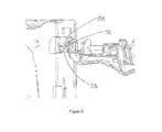
- Figure 11 shows the engagement of the locking element 20 with the receiving aperture 26.
- Figures 12 and 13 show a cross-section view of the receiving aperture 26. In Figure 13 , the stacking member 18 is shown to be in the stacking position (i.e. locked).
- a rib 28 is provided within the receiving aperture 26.
- the provision of the rib 28 strengthens, reinforces and provides rigidity to the receiving aperture 26.
- the rib 28 is partially flexible, thus assisting in the fitting of the protrusion 22 to the receiving aperture 26.
- the rib 28 is also of sufficient rigidity to strengthen the receiving aperture 26 and retain the locking element 20 therein.
- the rib 28 and receiving aperture 26 are manufactured in combination with one another, i.e. as a single unit.
- the manufacture of the rib 28 and receiving aperture 26 in combination advantageously facilitates the production thereof.
- the rib 28 and receiving aperture 26 are manufactured separately and subsequently combined.
- the rib 28 engages with the recess 24 of the locking element 20.
- the locking element 20 is retained within the receiving aperture 26 via the engagement of the rib 28 with the recess 24.
- the protrusion 22 of the locking element 20 is substantially oval in shape.
- the longest dimension of the protrusion 22 must be substantially parallel to the longest dimension of the receiving aperture 26.
- the stacking member 18 is rotated such that the protrusion 22 is no longer substantially parallel and is preferably substantially perpendicular to the receiving aperture 26.
- the locking element 20 is secured in place and may not be removed from the receiving aperture 26 when the stacking member 18 is in the stacking or filling conformation. This has the effect of preventing or reducing accidental or unwanted removal of the locking element 20 from the receiving aperture 26, and thus the stacking member 18 from the container 10.
- the configuration of the protrusion 22 during insertion or removal of the locking element from the receiving aperture of the wall is illustrated in Figure 14a , showing that the longest dimension of the protrusion 22 is parallel with the longest dimension of the receiving aperture 26.
- the configuration of the protrusion 22 when the stacking member 18 is in the stacking or filling position (i.e. in the locked position) is shown in Figure 14b .
- the protrusion 22 has been rotated such that the longest dimension thereof is no longer parallel to the longest dimension of the receiving aperture 26.
- the longest dimension of the protrusion 22 is preferably substantially perpendicular to the longest dimension of the receiving aperture 26.
- the protrusion 22 is secured within the receiving aperture 26 and may not be removed therefrom.
- Figures 15 to 17 show the engagement of the stacking member 18 with the receiving aperture 26.
- the stacking member is in the unlocked position.
- the stacking member 18 is inserted into the receiving aperture 26 via the protrusion 22 of the locking element 26 and is retained therein via the rib 28.
- the at least one stacking member 18 is flexible, to assist in fitting the stacking member 18 to the wall 14 of the container 10.
- the container 10 may be partially flexible, thus assisting in the alignment of the locking element 20 of the stacking member 18 with the receiving aperture 26 of the wall 14. After the components have been aligned, an operator may apply pressure to the stacking member 18 in order to fit the stacking member 18 to the wall 14 of the container 10.
- the present invention provides a collapsible container 10 comprising a base 12, a first pair of opposed walls 14 and a second pair of opposed walls 16, wherein the container further comprises means for securing 30, 32 the walls 14, 16 in the erected position, wherein the means for securing 30, 32 may be rotated into a locked position or a detachable position.
- means for securing 30, 32 are provided upon adjacent walls of the container in accordance with the second aspect of the invention.
- the means for securing comprise a receiving element 30, wherein the receiving element 30 comprises two ribs (30a, 30b), and a protrusion 32.
- the receiving element 30 is provided on a first pair of opposed walls 14 and the protrusion 32 is provided on a second pair of opposed walls 16.
- the protrusion 32 has a tooth-like shape, such that it fits between the two ribs 30a, 30b of the receiving element 30.
- a tight fit is formed between the protrusion 32 and ribs 30a, 30b, such that the protrusion 32 is held securely in place.
- the protrusion 32 may be easily inserted into or removed from the receiving element 30 (see Figure 20a ). In this position, the protrusion 32 is supported by one of the ribs 30b of the receiving element 30. The protrusion is subsequently rotated within the receiving element 30 to adopt a locked position ( Figure 20b ). In the locked position, the protrusion 32 is in a conformation wherein it cannot be easily removed from the receiving element 30. In this position, both ends of the protrusion are located between the ribs 30a, 30b of the receiving element 30. Thus, the adjacent walls of the container are secured to one another, preventing the unwanted or accidental detachment thereof. In order to remove the protrusion 32 from the receiving element 30, an operator must specifically rotate the protrusion relative to the receiving element such that it adopts the detachable position. It is only in this position that the walls of the container may be folded.
- biasing means may be provided for biasing the protrusion 32 in the locked position, thus providing a locking engagement between one of the walls of the first pair of opposed walls 14 in an upstanding position and both the walls of the second pair of walls 16 when the walls of the second pair of walls 16 are also in an upstanding position; and at least one actuator may be provided, which actuator is operable against the biasing means to move the protrusion 32 into the detachable position wherein the protrusion 32 may be released from the receiving element 30 so as to disengage the wall of the first pair of opposed walls 14 and both the walls of the second pair of walls 16.
- the biasing means may comprise a spring (not shown). More preferably, the biasing means may comprise an integral spring.
- the biasing means may be provided on a wall of the container. In another embodiment, the biasing means may be provided on the protrusion 32.
- the ribs 30a, 30b of the receiving element 30 partially surround the protrusion 32 and provide support for the protrusion 32 on engagement with the receiving element 30.
- the accidental or unwanted disconnection of the protrusion 32 from the receiving element 30 is prevented, such that the adjacent walls of the container are held in an erect position.
- the engagement of the protrusion 32 with the receiving element 30 is shown in Figure 21 .
- the container of the second aspect may further comprise at least one stacking member 18 in accordance with the first aspect of the invention.
- a stacking member 18 is attached to a wall 14 of the container 10 in accordance with the first or second aspect of the present invention by manipulating and moving the legs 18b of the stacking member 18 into a position wherein the legs 18b may be fitted to and engage with the container wall 14. This is achieved via the engagement of a locking element 20 with a receiving aperture 26 provided within the container wall 14.
- the stacking member 18 may be rotated to adopt a filling position, wherein the rod 18a of the stacking member sits adjacent to the wall of the container 14. In this position, the container 10 may be loaded with goods.
- the stacking member 18 may subsequently be rotated to adopt a stacking position, wherein the stacking member is positioned above the opening of the container such that it may support the base of another container positioned thereon.
- a locking element in accordance with the first aspect of the invention prevents the accidental or unwanted detachment of the stacking member from the container wall, which detachment would not be desirable during handling, stacking, washing or loading of the container.
- a means for securing in accordance with the second aspect of the invention provides support to the walls of the container, such that adjacent walls do not become accidentally detached from one another during loading, transport, handling or washing of the container.
- the present invention may relate to a container in accordance with the first and second aspects of the invention in combination, wherein the container may comprise both the locking element of the first aspect and the means for securing of the second aspect.
Landscapes
- Engineering & Computer Science (AREA)
- Mechanical Engineering (AREA)
- Ceramic Engineering (AREA)
- Stackable Containers (AREA)
- Rigid Containers With Two Or More Constituent Elements (AREA)
Abstract
Description
- The present invention relates to a container, and more particularly, to a container for the transport of consumer products, and their display in a retail outlet.
- Collapsible containers are known for use in many applications, including retail delivery. Typically, the containers are formed of plastics material and comprise a base and two pairs of opposed walls. Both the pairs of walls pivot about the base, at the lower edges thereof, so that the container can be collapsed into a substantially flat position when not in use.
- In applications where collapsible containers and nesting containers (with smaller base dimensions) are used together, solutions are known that provide stacking rails or bars that enable nesting containers to be stacked onto collapsible containers. In order to get bars sufficiently inboard to allow easy stacking location it is required that the normal method of folding the short ends first, be reversed (see
GB 2359066 GB 2431917 - In addition, during handling of the containers, the stacking bars may accidentally become detached from the container. The present application helps to overcome these issues and relates to a collapsible container comprising a locking element, wherein the container is substantially as described in
UK Patent Publication No. 2476856 - In a first aspect, the present invention relates to a collapsible container comprising a base, a first pair of opposed walls and a second pair of opposed walls, the first pair of opposed walls and the second pair of opposed walls defining an opening in the top of the container, wherein the container further comprises at least one stacking member which, when the container is erect, is movable between a stacking position in which the stacking member is positioned to support the base of another container thereon and a filling position in which the stacking member is substantially removed from the opening in the top of the container, and wherein the container further comprises at least one locking element for securing the at least one stacking member to the container. The provision of the at least one locking element is advantageous as it prevents the unwanted detachment of the at least one stacking member from the container during operation, for example, during handling, folding or washing of the container.
- Preferably, the at least one locking element comprises a snap fit securing means. The provision of a locking element comprising a snap fit securing means assists with the engagement of the stacking member with the container. In addition, the provision of a snap fit securing means has the advantage that the stacking member may be detachable if needed. Advantageously, the at least one locking element may comprise a resilient securing means.
- Preferably, the at least one locking element is provided on the at least one stacking member. Thus, in the event that the locking element is damaged during use, it will be necessary to replace only the stacking member, rather than the entire container.
- Preferably, the at least one locking element is integrally formed on the at least one stacking member. Advantageously, the integral formation of the locking element on the stacking member provides a structure which is more robust than that produced when the locking element and stacking member are provided separately and subsequently attached to one another. Furthermore, the integral formation of the locking element on the stacking member advantageously makes the stacking member cheaper and easier to manufacture.
- Advantageously, the provision of the at least one locking element assists in the folding of the container from an unfolded position to a folded position. In addition, the provision of the at least one locking element advantageously improves the longevity of the container.
- Typically, the at least one stacking member comprises an elongate bar and two legs at the extremities thereof, wherein the at least one locking element is provided at one end of at least one of the legs. The position of the at least one locking element at one end of the leg of the at least one stacking member has the effect that, after engagement of the at least one stacking member with the container, the at least one stacking member can pivot about the container wall from a filling position to a stacking position, and vice versa.
- In a preferred embodiment, the at least one locking element comprises at least one recess. Typically, the recess retains the locking element when engaged with the container wall.
- Preferably, the at least one locking element comprises a protrusion for engaging with the container. Preferably, the protrusion is substantially rounded in shape. The substantially rounded shape of the protrusion assists in the fitting of the locking element to the container wall.
- In a preferred embodiment, the protrusion is substantially oval in shape. The substantially oval shape of the protrusion provides specificity for fitting the protrusion to the container, preventing the locking element from being removed from the container when the stacking member is in the filling or stacking position or any position in between the filling or stacking position.
- Preferably, at least one of the second pair of opposed walls comprises at least one receiving aperture for receiving the at least one locking element. More preferably, the receiving aperture is provided to receive the protrusion of the at least one locking element. Preferably, the receiving aperture forms a slot or channel in which the protrusion of the locking element may slide after insertion of the locking element within the receiving aperture
- In one embodiment, the stacking member is in an unlocked position when the locking element is received within the receiving aperture. In another embodiment, the stacking member is in a locked position when the locking element is rotated within the receiving aperture such that it cannot be removed therefrom. In the unlocked position, the locking element may be inserted or removed into or from the receiving aperture. This allows the stacking member to be inserted into the receiving aperture during fitting to the container wall, and removed from the receiving aperture for repair. In the locked position, the locking element is secured such that it cannot be removed from the receiving aperture. This allows the stacking member to be secured to the container wall during the stacking or filling of the container.
- Typically, the longest dimension of the protrusion is substantially parallel to the longest dimension of the receiving aperture when the stacking member is in the unlocked position. In another embodiment, the longest dimension of the protrusion is rotated to a position wherein it is not substantially parallel to the longest dimension of the receiving aperture when the stacking member is in the locked position. Preferably, the longest dimension of the protrusion is substantially perpendicular to the longest dimension of the receiving aperture when the stacking member is in the locked position. Thus, the protrusion may be aligned with the longest dimension of the receiving aperture during insertion or removal of the stacking member from the receiving aperture, and may not be removed from the receiving aperture when the stacking member is in the stacking or filling position.
- Preferably, at least one rib is provided within the at least one receiving aperture. Advantageously, the rib strengthens, reinforces and provides rigidity to the receiving aperture. Preferably, the at least one rib is partially flexible, thus assisting in the fitting of the locking element to the receiving aperture. Additionally, the rib is of sufficient rigidity to provide partial resistance during insertion of the locking element, such that an improved fit is provided between the locking element and the receiving aperture. Preferably, the rib and receiving aperture are manufactured in combination. Advantageously, the manufacture of the rib and receiving aperture in combination facilitates the production thereof. In one embodiment, the rib and receiving aperture are manufactured separately and subsequently combined.
- In a preferred embodiment, the rib engages with the at least one recess of the locking element. Typically, the locking element is inserted into the receiving aperture via the protrusion and engages with the rib via the recess. Thus, the rib retains the locking element within the receiving aperture via the recess, strengthening the engagement of the locking element with the receiving aperture of the container wall.
- In a preferred embodiment, the at least one stacking member is flexible to allow for fitting of the stacking member to the wall of the container. Advantageously, the flexibility of the stacking member assists in the fitting of the stacking member to the wall of the container.
- In a second aspect, the present invention provides a collapsible container comprising a base, a first pair of opposed walls and a second pair of opposed walls, wherein the container further comprises means for securing the walls in the erected position, wherein the means for securing may be rotated into a locked position or a detachable position.
- Preferably, the means for securing the walls in the erected position comprises resilient means. The resilient means assist in securing the walls of the container in the erected position. In addition, the provision of resilient means has the advantage that the walls of the container may be detachable. The means for securing may also comprise a snap fit securing means.
- Preferably, the means for securing comprises at least one protrusion provided on at least one of the second pair of opposed walls, and at least one corresponding receiving element provided on an adjacent wall.
- Advantageously, the shape of the at least one protrusion is designed such that it engages with the at least one receiving element. Preferably, the at least one protrusion has a tooth-like shape. Thus, the shape of the protrusion and the receiving element provides a specificity of interaction, such that the protrusion forms a tight fit with the receiving element.
- Typically, the at least one receiving element comprises at least two ribs which partially surround the protrusion on engagement therewith. The provision of at least two ribs that partially surround the protrusion provides support for the protrusion, such that the protrusion is held securely within the receiving element.
- In one embodiment, the protrusion is in a detachable position wherein it can be easily inserted into or removed from the receiving element. In a second embodiment, the protrusion is rotated within the receiving element to adopt a locked position. In the locked position, the protrusion cannot be easily removed from the receiving element. When the protrusion is in the locked position, the adjacent walls of the container are secured to one another, preventing the unwanted or accidental detachment thereof. In order to remove the protrusion from the receiving element, an operator must specifically rotate the protrusion such that it adopts the detachable position. It is only in this position that the walls of the container may be folded.
- In a preferred embodiment, biasing means may be provided for biasing the protrusion in the locked position, thus providing a locking engagement between one of the walls of the first pair of opposed walls in an upstanding position and both the walls of the second pair of walls when the walls of the second pair of walls are also in an upstanding position; and at least one actuator may be provided, which actuator is operable against the biasing means to move the protrusion into the detachable position wherein the protrusion may be released from the receiving element so as to disengage the wall of the first pair of opposed walls and both the walls of the second pair of walls. Preferably, the biasing means may comprise a spring. More preferably, the biasing means may comprise an integral spring.
- In one embodiment, the container of the second aspect further comprises at least one stacking member in accordance with the first aspect of the invention, such that when the stacking member is in the stacking position, another container may be stacked thereon.
- The present invention will now be described in more detail, by way of example only, and with reference to the Figures, in which:
-
Figure 1 is a perspective view of a collapsible container according to a first aspect of the invention; -
Figure 2 is an overhead view of the collapsible container, showing the stacking member in the stacking position; -
Figure 3 is a perspective view of the collapsible container, showing a stacking member in the filling position; -
Figure 4 is a perspective view of the collapsible container, showing the position of two of the walls as one of the walls starts to collapse; -
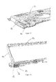
Figure 5 is a front view of a portion of a stacking member suitable for use with the container ofFigure 1 ; -
Figure 6 is a perspective view of a portion of a stacking member suitable for use with the container ofFigure 1 ; -
Figure 7 is a rear view of a portion of a stacking member comprising a locking element suitable for use with the container ofFigure 1 ; -
Figure 8 is a front view of a portion of a stacking member comprising a locking element suitable for use with the container ofFigure 1 ; -
Figure 9 is a perspective view of a portion of a wall of the container, showing a receiving aperture provided therein; -
Figure 10 is a perspective view of a portion of a wall of the container, showing a receiving aperture and a rib provided therein; -
Figure 11 is a perspective view of a stacking member and a wall of the container, comprising a receiving aperture and a rib; -
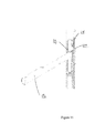
Figure 12 is a cross section view of a portion of a wall of the container, showing a receiving aperture and a rib; -
Figure 13 is a cross section view of a portion of a wall of the container and a stacking member, wherein the stacking member is in the stacking position; -
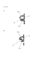
Figure 14a is an end view of a receiving aperture of a wall of the container, and a protrusion of a locking element of a stacking member, wherein the stacking member is in the unlocked position; -
Figure 14b is an end view of a receiving aperture of a wall of the container and a protrusion of a locking element of a stacking member, wherein the stacking member is in the locked position. -
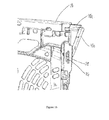
Figure 15 is a side view of a stacking member and a receiving aperture provided within the wall of the container, wherein the stacking member is in the unlocked position; -
Figure 16 is a rear view of a portion of a wall of the container and a stacking member; -
Figure 17 is a front view of a wall of the container and a stacking member in the unlocked position; -
Figure 18 is a perspective view of a portion of a wall of the container in accordance with the second aspect of the invention, comprising a receiving element; -
Figure 19 is a perspective view of a protrusion provided on an adjacent wall of the container ofFigure 18 (wherein the adjacent wall of the container has been removed); -
Figure 20a is a plan view of the means for securing in accordance with the second aspect of the invention, wherein the means for securing is in a detachable position; -
Figure 20b is a plan view of the means for securing in accordance with the second aspect of the invention, wherein the means for securing is in a locked position; -
Figure 21 is a perspective view of a portion of a wall of the container ofFigure 18 , showing the engagement of a receiving element provided on a first wall with a protrusion provided on an adjacent wall (wherein the adjacent wall has been removed). - In a first aspect, the present invention relates to a
collapsible container 10 comprising a base 12, a first pair of opposedwalls 14 and a second pair of opposedwalls 16, the first pair of opposedwalls 14 and the second pair of opposedwalls 16 defining an opening in the top of the container, wherein thecontainer 10 further comprises at least one stackingmember 18 which, when thecontainer 10 is erect, is movable between a stacking position in which the stackingmember 18 is positioned to support the base of another container thereon and a filling position in which the stackingmember 18 is substantially removed from the opening in the top of thecontainer 10, and wherein thecontainer 10 further comprises at least one lockingelement 20 for securing the at least one stackingmember 18 to thecontainer 10. The provision of the at least one lockingelement 20 is advantageous as it prevents the unwanted detachment of the at least one stackingmember 18 from thecontainer 10 during operation, for example, during handling, folding or washing of the container. -
Figure 1 illustrates acollapsible container 10 in accordance with one embodiment of the present invention. Thecontainer 10 comprises a base 12, a first pair of opposedwalls 14 and a second pair of opposedwalls 16. The first and second pair of opposedwalls -
Container 10 is typically formed by injection moulding from a suitable plastics material, with a pattern of openings in the base 12 andwalls unfilled container 10. A handle opening is provided in a central, upper area of each of the walls of the first pair of opposedwalls 14, for use in carrying thecontainer 10. As the skilled person will appreciate, the shape, configuration and dimensions of thecontainer 10, including the relative proportions and thicknesses of the base 12 andwalls walls container 10 are typically moulded as separate parts and assembled together by snap-fit connection or otherwise. - Stacking
members 18 are located at either end of the container, wherein therod 18a is substantially parallel and the legs 18b are substantially perpendicular to the first pair of opposedwalls 14. Each stackingmember 18 comprises arod 18a, which may be approximately the same length as the walls of the first pair of opposedwalls 14 and extends horizontally across the container when the stackingmember 18 is in the stacking position, and two legs 18b, which extend downwards from either end of therod 18a when the stacking member is in the filling position. Each stackingmember 18 pivots about one of the walls of the first pair of opposedwalls 14. - The
container 10 is designed such that the stackingmembers 18 can adopt the stacking position (in which the stackingmembers 18 rotate forwards such that they are positioned over the opening in the top of thecontainer 10, as shown inFigure 2 ), the filling position (in which the stacking members are aligned within thewall 14, as shown inFigure 3 ), and intermediate positions (between the filling position and the stacking position). When the stackingmembers 18 are in the filling position, therods 18a are positioned adjacent to the walls of the first pair ofwalls 14. Therods 18a may be slightly shorter in length than the longest dimension of thewalls 14, such that they may be moved within the container and rotated from the filling position to the stacking position, and vice versa. An important feature of the present invention is that therods 18a fit within the side wall of thecontainer 14. -
Figures 5 and 6 illustrate a stacking member in accordance with the present invention. - With reference to
Figures 7 and8 , a lockingelement 20 is provided at an end of the leg 18b of the stackingmember 18, at a position distal to the point of connection of the leg 18b to therod 18a. It would be understood that the lockingelement 20 may be provided at an end of one or both legs 18b of the stackingmember 18. The lockingelement 20 extends substantially perpendicular to the leg 18b of the stackingmember 18 and comprises a protrusion 22. The locking element also comprises arecess 24. The protrusion 22 is positioned substantially adjacent to therecess 24, such that the lockingelement 20 has a hook-like conformation. The conformation of the lockingelement 20 assists in securing the stackingmember 18 to thecontainer 10, thus preventing accidental or unwanted disconnection of the stackingmember 18 from thecontainer 10 during handling, for example when goods are loaded into the container, or when the walls of the container are manipulated by an operator. - The
wall 14 of thecontainer 10 comprises a receivingaperture 26, as can be seen inFigures 9 and10 . The receivingaperture 26 is provided at a lateral edge of thewall 14 and is substantially parallel to the lateral edge of thewall 14. The receivingaperture 26 forms an elongate slot or channel. Typically, the protrusion 22 of the lockingelement 20 is substantially rounded in shape to assist in fitting the lockingelement 20 to thewall 14 of thecontainer 10. The protrusion 22 is inserted into the receivingaperture 26 and may slide therein.Figure 11 shows the engagement of the lockingelement 20 with the receivingaperture 26.Figures 12 and 13 show a cross-section view of the receivingaperture 26. InFigure 13 , the stackingmember 18 is shown to be in the stacking position (i.e. locked). - Typically, a
rib 28 is provided within the receivingaperture 26. The provision of therib 28 strengthens, reinforces and provides rigidity to the receivingaperture 26. In addition, therib 28 is partially flexible, thus assisting in the fitting of the protrusion 22 to the receivingaperture 26. Furthermore, therib 28 is also of sufficient rigidity to strengthen the receivingaperture 26 and retain the lockingelement 20 therein. - Preferably, the
rib 28 and receivingaperture 26 are manufactured in combination with one another, i.e. as a single unit. The manufacture of therib 28 and receivingaperture 26 in combination advantageously facilitates the production thereof. In one embodiment, therib 28 and receivingaperture 26 are manufactured separately and subsequently combined. - When the locking
element 20 is inserted into the receivingaperture 26, therib 28 engages with therecess 24 of the lockingelement 20. Thus, the lockingelement 20 is retained within the receivingaperture 26 via the engagement of therib 28 with therecess 24. - Preferably, the protrusion 22 of the locking
element 20 is substantially oval in shape. Upon insertion or removal of the lockingelement 20 from the receiving aperture 26 (i.e. when the stacking member is in the unlocked position), the longest dimension of the protrusion 22 must be substantially parallel to the longest dimension of the receivingaperture 26. When the stackingmember 18 is moved to adopt the stacking or filling position, or any position in between the stacking position and the filling position, (i.e. when the stacking member is in the locked position), the stackingmember 18 is rotated such that the protrusion 22 is no longer substantially parallel and is preferably substantially perpendicular to the receivingaperture 26. Thus, the lockingelement 20 is secured in place and may not be removed from the receivingaperture 26 when the stackingmember 18 is in the stacking or filling conformation. This has the effect of preventing or reducing accidental or unwanted removal of the lockingelement 20 from the receivingaperture 26, and thus the stackingmember 18 from thecontainer 10. - The configuration of the protrusion 22 during insertion or removal of the locking element from the receiving aperture of the wall (i.e. when the stacking member is in the unlocked position) is illustrated in
Figure 14a , showing that the longest dimension of the protrusion 22 is parallel with the longest dimension of the receivingaperture 26. The configuration of the protrusion 22 when the stackingmember 18 is in the stacking or filling position (i.e. in the locked position) is shown inFigure 14b . In this conformation, the protrusion 22 has been rotated such that the longest dimension thereof is no longer parallel to the longest dimension of the receivingaperture 26. Indeed, the longest dimension of the protrusion 22 is preferably substantially perpendicular to the longest dimension of the receivingaperture 26. Thus, in this position, the protrusion 22 is secured within the receivingaperture 26 and may not be removed therefrom. -
Figures 15 to 17 show the engagement of the stackingmember 18 with the receivingaperture 26. InFigures 15 and17 , the stacking member is in the unlocked position. As discussed above, the stackingmember 18 is inserted into the receivingaperture 26 via the protrusion 22 of the lockingelement 26 and is retained therein via therib 28. - Preferably, the at least one stacking
member 18 is flexible, to assist in fitting the stackingmember 18 to thewall 14 of thecontainer 10. - In addition, the
container 10 may be partially flexible, thus assisting in the alignment of the lockingelement 20 of the stackingmember 18 with the receivingaperture 26 of thewall 14. After the components have been aligned, an operator may apply pressure to the stackingmember 18 in order to fit the stackingmember 18 to thewall 14 of thecontainer 10. - In a second aspect, the present invention provides a
collapsible container 10 comprising a base 12, a first pair of opposedwalls 14 and a second pair of opposedwalls 16, wherein the container further comprises means for securing 30, 32 thewalls - With reference to
Figures 18 and 19 , means for securing 30, 32 are provided upon adjacent walls of the container in accordance with the second aspect of the invention. The means for securing comprise a receiving element 30, wherein the receiving element 30 comprises two ribs (30a, 30b), and aprotrusion 32. The receiving element 30 is provided on a first pair of opposedwalls 14 and theprotrusion 32 is provided on a second pair of opposedwalls 16. Theprotrusion 32 has a tooth-like shape, such that it fits between the tworibs protrusion 32 with the receiving element 30, a tight fit is formed between theprotrusion 32 andribs protrusion 32 is held securely in place. - In the detachable position, the
protrusion 32 may be easily inserted into or removed from the receiving element 30 (seeFigure 20a ). In this position, theprotrusion 32 is supported by one of theribs 30b of the receiving element 30. The protrusion is subsequently rotated within the receiving element 30 to adopt a locked position (Figure 20b ). In the locked position, theprotrusion 32 is in a conformation wherein it cannot be easily removed from the receiving element 30. In this position, both ends of the protrusion are located between theribs protrusion 32 from the receiving element 30, an operator must specifically rotate the protrusion relative to the receiving element such that it adopts the detachable position. It is only in this position that the walls of the container may be folded. - In a preferred embodiment, biasing means may be provided for biasing the
protrusion 32 in the locked position, thus providing a locking engagement between one of the walls of the first pair of opposedwalls 14 in an upstanding position and both the walls of the second pair ofwalls 16 when the walls of the second pair ofwalls 16 are also in an upstanding position; and at least one actuator may be provided, which actuator is operable against the biasing means to move theprotrusion 32 into the detachable position wherein theprotrusion 32 may be released from the receiving element 30 so as to disengage the wall of the first pair of opposedwalls 14 and both the walls of the second pair ofwalls 16. Preferably, the biasing means may comprise a spring (not shown). More preferably, the biasing means may comprise an integral spring. In one embodiment, the biasing means may be provided on a wall of the container. In another embodiment, the biasing means may be provided on theprotrusion 32. - Typically, the
ribs protrusion 32 and provide support for theprotrusion 32 on engagement with the receiving element 30. As a result, the accidental or unwanted disconnection of theprotrusion 32 from the receiving element 30 is prevented, such that the adjacent walls of the container are held in an erect position. The engagement of theprotrusion 32 with the receiving element 30 is shown inFigure 21 . - The container of the second aspect may further comprise at least one stacking
member 18 in accordance with the first aspect of the invention. - In use, a stacking
member 18 is attached to awall 14 of thecontainer 10 in accordance with the first or second aspect of the present invention by manipulating and moving the legs 18b of the stackingmember 18 into a position wherein the legs 18b may be fitted to and engage with thecontainer wall 14. This is achieved via the engagement of a lockingelement 20 with a receivingaperture 26 provided within thecontainer wall 14. After fitting, the stackingmember 18 may be rotated to adopt a filling position, wherein therod 18a of the stacking member sits adjacent to the wall of thecontainer 14. In this position, thecontainer 10 may be loaded with goods. The stackingmember 18 may subsequently be rotated to adopt a stacking position, wherein the stacking member is positioned above the opening of the container such that it may support the base of another container positioned thereon. The provision of a locking element in accordance with the first aspect of the invention prevents the accidental or unwanted detachment of the stacking member from the container wall, which detachment would not be desirable during handling, stacking, washing or loading of the container. In addition, the provision of a means for securing in accordance with the second aspect of the invention provides support to the walls of the container, such that adjacent walls do not become accidentally detached from one another during loading, transport, handling or washing of the container. - The skilled person would understand that the present invention may relate to a container in accordance with the first and second aspects of the invention in combination, wherein the container may comprise both the locking element of the first aspect and the means for securing of the second aspect.
Claims (27)
- A collapsible container comprising a base, a first pair of opposed walls and a second pair of opposed walls, the first pair of opposed walls and the second pair of opposed walls defining an opening in the top of the container, wherein the container further comprises at least one stacking member which, when the container is erect, is movable between a stacking position in which the stacking member is positioned to support the base of another container thereon and a filling position in which the stacking member is substantially removed from the opening in the top of the container, and wherein the container further comprises at least one locking element for securing the at least one stacking member to the container.
- A collapsible container according to claim 1, wherein the at least one locking element comprises a snap fit securing means.
- A collapsible container according to claim 1 or 2, wherein the at least one locking element is provided on the at least one stacking member.
- A collapsible container according to claim 1, 2 or 3, wherein the at least one locking element is integrally formed on the at least one stacking member.
- A collapsible container according to any one of the preceding claims, wherein the at least one stacking member comprises an elongate bar and two legs at the extremities thereof, wherein the at least one locking element is provided at one end of at least one of the legs.
- A collapsible container according to any one of the preceding claims, wherein the at least one locking element comprises at least one recess.
- A collapsible container according to any one of the preceding claims, wherein the at least one locking element comprises a protrusion for engaging with the container.
- A collapsible container according to claim 7, wherein the protrusion is substantially rounded in shape.
- A collapsible container according to claim 7 or 8, wherein the protrusion is substantially oval in shape.
- A collapsible container according to any one of the preceding claims, wherein at least one of the second pair of opposed walls comprises at least one receiving aperture for receiving the at least one locking element.
- A collapsible container according to claim 10, wherein the receiving aperture is provided to receive the protrusion of the at least one locking element.
- A collapsible container according to claim 10 or 11, wherein the stacking member is in an unlocked position when the locking element is received within the receiving aperture.
- A collapsible container according to claim 10 or 11, wherein the stacking member is in a locked position when the locking element is rotated within the receiving aperture such that it cannot be removed therefrom.
- A collapsible container according to claim 12, wherein the longest dimension of the protrusion is substantially parallel to the longest dimension of the receiving aperture when the stacking member is in the unlocked position.
- A collapsible container according to claim 13, wherein the longest dimension of the protrusion is rotated to a position wherein it is not substantially parallel to the longest dimension of the receiving aperture when the stacking member is in the locked position.
- A collapsible container according to claim 13 or 15, wherein the longest dimension of the protrusion is substantially perpendicular to the longest dimension of the receiving aperture wherein the stacking member is in the locked position.
- A collapsible container according to any one of claims 10 to 16, wherein at least one rib is provided within the at least one receiving aperture.
- A collapsible container according to any one of the preceding claims, wherein the at least one stacking member is flexible to allow for fitting of the stacking member to the wall of the container.
- A stacking member as defined in any one of claims 1 to 18.
- A locking element as defined in any one of claims 1 to 18.
- A collapsible container comprising a base, a first pair of opposed walls and a second pair of opposed walls, wherein the container further comprises means for securing the walls in the erected position, wherein the means for securing may be rotated into a locked position or a detachable position.
- A collapsible container according to claim 21, wherein the means for securing the walls in the erected position comprises resilient means.
- A collapsible container according to claim 21 or 22, wherein the means for securing comprises at least one protrusion provided on at least one of the second pair of opposed walls, and at least one corresponding receiving element provided on an adjacent wall.
- A collapsible container according to claim 23, wherein the shape of the at least one protrusion is designed such that it engages with the at least one receiving element.
- A collapsible container according to claim 24, wherein the at least one protrusion has a tooth-like shape.
- A collapsible container according to claim 23, 24 or 25, wherein the at least one receiving element comprises at least two ribs which partially surround the protrusion on engagement therewith.
- A collapsible container according to any one of claims 21 to 26 wherein the container further comprises at least one stacking member as defined in claims 1 to 18.
Priority Applications (4)
| Application Number | Priority Date | Filing Date | Title |
|---|---|---|---|
| PL12177182T PL2548809T3 (en) | 2011-07-22 | 2012-07-19 | Collapsible container |
| PL15187926T PL2993141T3 (en) | 2011-07-22 | 2012-07-19 | Collabsible container |
| DK15187926.9T DK2993141T3 (en) | 2011-07-22 | 2012-07-19 | Collapsible container |
| EP15187926.9A EP2993141B1 (en) | 2011-07-22 | 2012-07-19 | Collabsible container |
Applications Claiming Priority (1)
| Application Number | Priority Date | Filing Date | Title |
|---|---|---|---|
| GBGB1112660.4A GB201112660D0 (en) | 2011-07-22 | 2011-07-22 | Collapsible container |
Related Child Applications (2)
| Application Number | Title | Priority Date | Filing Date |
|---|---|---|---|
| EP15187926.9A Division EP2993141B1 (en) | 2011-07-22 | 2012-07-19 | Collabsible container |
| EP15187926.9A Division-Into EP2993141B1 (en) | 2011-07-22 | 2012-07-19 | Collabsible container |
Publications (2)
| Publication Number | Publication Date |
|---|---|
| EP2548809A1 true EP2548809A1 (en) | 2013-01-23 |
| EP2548809B1 EP2548809B1 (en) | 2016-04-27 |
Family
ID=44652188
Family Applications (2)
| Application Number | Title | Priority Date | Filing Date |
|---|---|---|---|
| EP12177182.8A Active EP2548809B1 (en) | 2011-07-22 | 2012-07-19 | Collapsible container |
| EP15187926.9A Active EP2993141B1 (en) | 2011-07-22 | 2012-07-19 | Collabsible container |
Family Applications After (1)
| Application Number | Title | Priority Date | Filing Date |
|---|---|---|---|
| EP15187926.9A Active EP2993141B1 (en) | 2011-07-22 | 2012-07-19 | Collabsible container |
Country Status (7)
| Country | Link |
|---|---|
| EP (2) | EP2548809B1 (en) |
| DK (2) | DK2993141T3 (en) |
| ES (2) | ES2574182T3 (en) |
| GB (1) | GB201112660D0 (en) |
| HU (1) | HUE029082T2 (en) |
| PL (2) | PL2993141T3 (en) |
| PT (2) | PT2548809E (en) |
Cited By (4)
| Publication number | Priority date | Publication date | Assignee | Title |
|---|---|---|---|---|
| EP2894108A1 (en) | 2014-01-10 | 2015-07-15 | Schoeller Allibert GmbH | Container with stacking rail with anti-slide coating |
| US10065763B2 (en) | 2016-09-15 | 2018-09-04 | Arena Packaging, Llc | Wall latching system |
| FR3118951A1 (en) | 2021-01-19 | 2022-07-22 | Thegreenflux | Collapsible container in particular for transporting fruit and vegetables |
| CN118524970A (en) * | 2022-01-16 | 2024-08-20 | 凯特尔家庭园艺用品有限公司 | Foldable Box |
Families Citing this family (1)
| Publication number | Priority date | Publication date | Assignee | Title |
|---|---|---|---|---|
| EP3536625A1 (en) * | 2018-03-08 | 2019-09-11 | Schoeller Allibert GmbH | Stackable nestable container |
Citations (5)
| Publication number | Priority date | Publication date | Assignee | Title |
|---|---|---|---|---|
| GB2359066A (en) | 1999-12-16 | 2001-08-15 | Mckechnie Components Ltd | Collapsible stacking/nesting container |
| GB2431917A (en) | 2005-11-02 | 2007-05-09 | Linpac Materials Handling Ltd | Stackable collapsible container |
| EP2039615A1 (en) * | 2007-09-24 | 2009-03-25 | Rehrig Pacific Company | Container |
| EP2194001A1 (en) * | 2008-12-02 | 2010-06-09 | Rehrig Pacific Company | Collapsible container |
| GB2476856A (en) | 2010-01-11 | 2011-07-13 | Linpac Allibert Ltd | A collapsible, stackable container |
Family Cites Families (5)
| Publication number | Priority date | Publication date | Assignee | Title |
|---|---|---|---|---|
| GB2353274B (en) * | 1999-08-16 | 2002-12-24 | Lin Pac Mouldings | A container assembly |
| DE60006715T2 (en) * | 1999-12-16 | 2004-09-02 | C. G. Paxton Ltd., Walsall | CONTAINER |
| GB2373240B (en) * | 2001-03-02 | 2004-10-06 | Mckechnie Invest Holdings | A stackable and nestable container |
| DE10200070B4 (en) * | 2002-01-03 | 2012-03-22 | Schoeller Arca Systems Gmbh | Folding container with a container bottom and four hinged side walls |
| AT507858B1 (en) * | 2009-02-12 | 2011-04-15 | Leisch Beratungs Und Beteiligungs Gmbh | folding |
-
2011
- 2011-07-22 GB GBGB1112660.4A patent/GB201112660D0/en not_active Ceased
-
2012
- 2012-07-19 EP EP12177182.8A patent/EP2548809B1/en active Active
- 2012-07-19 DK DK15187926.9T patent/DK2993141T3/en active
- 2012-07-19 PT PT121771828T patent/PT2548809E/en unknown
- 2012-07-19 PL PL15187926T patent/PL2993141T3/en unknown
- 2012-07-19 ES ES12177182.8T patent/ES2574182T3/en active Active
- 2012-07-19 EP EP15187926.9A patent/EP2993141B1/en active Active
- 2012-07-19 DK DK12177182.8T patent/DK2548809T3/en active
- 2012-07-19 PL PL12177182T patent/PL2548809T3/en unknown
- 2012-07-19 HU HUE12177182A patent/HUE029082T2/en unknown
- 2012-07-19 ES ES15187926T patent/ES2697332T3/en active Active
- 2012-07-19 PT PT15187926T patent/PT2993141T/en unknown
Patent Citations (5)
| Publication number | Priority date | Publication date | Assignee | Title |
|---|---|---|---|---|
| GB2359066A (en) | 1999-12-16 | 2001-08-15 | Mckechnie Components Ltd | Collapsible stacking/nesting container |
| GB2431917A (en) | 2005-11-02 | 2007-05-09 | Linpac Materials Handling Ltd | Stackable collapsible container |
| EP2039615A1 (en) * | 2007-09-24 | 2009-03-25 | Rehrig Pacific Company | Container |
| EP2194001A1 (en) * | 2008-12-02 | 2010-06-09 | Rehrig Pacific Company | Collapsible container |
| GB2476856A (en) | 2010-01-11 | 2011-07-13 | Linpac Allibert Ltd | A collapsible, stackable container |
Cited By (6)
| Publication number | Priority date | Publication date | Assignee | Title |
|---|---|---|---|---|
| EP2894108A1 (en) | 2014-01-10 | 2015-07-15 | Schoeller Allibert GmbH | Container with stacking rail with anti-slide coating |
| DE102014100265A1 (en) | 2014-01-10 | 2015-07-16 | Schoeller Arca Systems Gmbh | Container with stacking strap with anti-slip coating |
| US10065763B2 (en) | 2016-09-15 | 2018-09-04 | Arena Packaging, Llc | Wall latching system |
| FR3118951A1 (en) | 2021-01-19 | 2022-07-22 | Thegreenflux | Collapsible container in particular for transporting fruit and vegetables |
| WO2022157444A1 (en) | 2021-01-19 | 2022-07-28 | Thegreenflux | Collapsible container in particular for transporting fruits and vegetables |
| CN118524970A (en) * | 2022-01-16 | 2024-08-20 | 凯特尔家庭园艺用品有限公司 | Foldable Box |
Also Published As
| Publication number | Publication date |
|---|---|
| PL2993141T3 (en) | 2019-03-29 |
| DK2993141T3 (en) | 2018-12-10 |
| HUE029082T2 (en) | 2017-02-28 |
| PL2548809T3 (en) | 2017-04-28 |
| DK2548809T3 (en) | 2016-08-01 |
| GB201112660D0 (en) | 2011-09-07 |
| PT2993141T (en) | 2018-11-29 |
| EP2993141B1 (en) | 2018-08-29 |
| ES2574182T3 (en) | 2016-06-15 |
| ES2697332T3 (en) | 2019-01-23 |
| EP2548809B1 (en) | 2016-04-27 |
| EP2993141A1 (en) | 2016-03-09 |
| PT2548809E (en) | 2016-06-02 |
Similar Documents
| Publication | Publication Date | Title |
|---|---|---|
| US8485376B2 (en) | Folding container | |
| EP2993141B1 (en) | Collabsible container | |
| US11116174B2 (en) | Collapsible pet crate | |
| CN100406354C (en) | Collapsible container for transport and storage | |
| KR101831840B1 (en) | Folding box | |
| CA2918113C (en) | Collapsible crate | |
| US20110114581A1 (en) | Collapsible clothes rack | |
| ITVI20130059A1 (en) | HANGER WITH FOLDABLE / REMOVABLE HOOK | |
| US20160286955A1 (en) | Collapsible Serving Cart with Wheels | |
| MX2010011166A (en) | Collapsible bin. | |
| CA3009998C (en) | Cart and dolly handle with hinged middle beam | |
| US20240043171A1 (en) | Containers for oil bottles or the like | |
| JP2009514745A (en) | Slide and clip-in corner support | |
| US20150225004A1 (en) | Collapsible Rolling Cart | |
| EP2289811A1 (en) | Collapsible crate | |
| EP3230172A1 (en) | A storage and display device and system | |
| US10351295B2 (en) | Display container | |
| EP2354025A2 (en) | Container | |
| CA2686829A1 (en) | Collapsible container | |
| EP2690026A1 (en) | Container | |
| CA2973922C (en) | Display container | |
| GB2494642A (en) | Folding container with stacking member | |
| EP3887271B1 (en) | Foldable container | |
| CN107708487A (en) | Beverage case trolley | |
| EP3339205A1 (en) | Folding container |
Legal Events
| Date | Code | Title | Description |
|---|---|---|---|
| PUAI | Public reference made under article 153(3) epc to a published international application that has entered the european phase |
Free format text: ORIGINAL CODE: 0009012 |
|
| AK | Designated contracting states |
Kind code of ref document: A1 Designated state(s): AL AT BE BG CH CY CZ DE DK EE ES FI FR GB GR HR HU IE IS IT LI LT LU LV MC MK MT NL NO PL PT RO RS SE SI SK SM TR |
|
| AX | Request for extension of the european patent |
Extension state: BA ME |
|
| 17P | Request for examination filed |
Effective date: 20130704 |
|
| RBV | Designated contracting states (corrected) |
Designated state(s): AL AT BE BG CH CY CZ DE DK EE ES FI FR GB GR HR HU IE IS IT LI LT LU LV MC MK MT NL NO PL PT RO RS SE SI SK SM TR |
|
| RAP1 | Party data changed (applicant data changed or rights of an application transferred) |
Owner name: IFCO SYSTEMS GMBH |
|
| 17Q | First examination report despatched |
Effective date: 20150306 |
|
| GRAP | Despatch of communication of intention to grant a patent |
Free format text: ORIGINAL CODE: EPIDOSNIGR1 |
|
| INTG | Intention to grant announced |
Effective date: 20151106 |
|
| GRAS | Grant fee paid |
Free format text: ORIGINAL CODE: EPIDOSNIGR3 |
|
| GRAA | (expected) grant |
Free format text: ORIGINAL CODE: 0009210 |
|
| AK | Designated contracting states |
Kind code of ref document: B1 Designated state(s): AL AT BE BG CH CY CZ DE DK EE ES FI FR GB GR HR HU IE IS IT LI LT LU LV MC MK MT NL NO PL PT RO RS SE SI SK SM TR |
|
| REG | Reference to a national code |
Ref country code: GB Ref legal event code: FG4D |
|
| REG | Reference to a national code |
Ref country code: CH Ref legal event code: EP Ref country code: CH Ref legal event code: NV Representative=s name: BOVARD AG, CH |
|
| REG | Reference to a national code |
Ref country code: AT Ref legal event code: REF Ref document number: 794509 Country of ref document: AT Kind code of ref document: T Effective date: 20160515 |
|
| REG | Reference to a national code |
Ref country code: IE Ref legal event code: FG4D |
|
| REG | Reference to a national code |
Ref country code: PT Ref legal event code: SC4A Free format text: AVAILABILITY OF NATIONAL TRANSLATION Effective date: 20160523 |
|
| REG | Reference to a national code |
Ref country code: NL Ref legal event code: FP |
|
| REG | Reference to a national code |
Ref country code: FR Ref legal event code: PLFP Year of fee payment: 5 |
|
| REG | Reference to a national code |
Ref country code: ES Ref legal event code: FG2A Ref document number: 2574182 Country of ref document: ES Kind code of ref document: T3 Effective date: 20160615 |
|
| REG | Reference to a national code |
Ref country code: DE Ref legal event code: R096 Ref document number: 602012017564 Country of ref document: DE |
|
| REG | Reference to a national code |
Ref country code: RO Ref legal event code: EPE |
|
| REG | Reference to a national code |
Ref country code: DK Ref legal event code: T3 Effective date: 20160726 |
|
| REG | Reference to a national code |
Ref country code: SE Ref legal event code: TRGR |
|
| REG | Reference to a national code |
Ref country code: LT Ref legal event code: MG4D |
|
| REG | Reference to a national code |
Ref country code: NO Ref legal event code: T2 Effective date: 20160427 |
|
| PG25 | Lapsed in a contracting state [announced via postgrant information from national office to epo] |
Ref country code: LT Free format text: LAPSE BECAUSE OF FAILURE TO SUBMIT A TRANSLATION OF THE DESCRIPTION OR TO PAY THE FEE WITHIN THE PRESCRIBED TIME-LIMIT Effective date: 20160427 Ref country code: FI Free format text: LAPSE BECAUSE OF FAILURE TO SUBMIT A TRANSLATION OF THE DESCRIPTION OR TO PAY THE FEE WITHIN THE PRESCRIBED TIME-LIMIT Effective date: 20160427 |
|
| REG | Reference to a national code |
Ref country code: SK Ref legal event code: T3 Ref document number: E 21247 Country of ref document: SK |
|
| PG25 | Lapsed in a contracting state [announced via postgrant information from national office to epo] |
Ref country code: LV Free format text: LAPSE BECAUSE OF FAILURE TO SUBMIT A TRANSLATION OF THE DESCRIPTION OR TO PAY THE FEE WITHIN THE PRESCRIBED TIME-LIMIT Effective date: 20160427 Ref country code: RS Free format text: LAPSE BECAUSE OF FAILURE TO SUBMIT A TRANSLATION OF THE DESCRIPTION OR TO PAY THE FEE WITHIN THE PRESCRIBED TIME-LIMIT Effective date: 20160427 Ref country code: HR Free format text: LAPSE BECAUSE OF FAILURE TO SUBMIT A TRANSLATION OF THE DESCRIPTION OR TO PAY THE FEE WITHIN THE PRESCRIBED TIME-LIMIT Effective date: 20160427 |
|
| PG25 | Lapsed in a contracting state [announced via postgrant information from national office to epo] |
Ref country code: BE Free format text: LAPSE BECAUSE OF NON-PAYMENT OF DUE FEES Effective date: 20160731 |
|
| REG | Reference to a national code |
Ref country code: DE Ref legal event code: R097 Ref document number: 602012017564 Country of ref document: DE |
|
| PG25 | Lapsed in a contracting state [announced via postgrant information from national office to epo] |
Ref country code: EE Free format text: LAPSE BECAUSE OF FAILURE TO SUBMIT A TRANSLATION OF THE DESCRIPTION OR TO PAY THE FEE WITHIN THE PRESCRIBED TIME-LIMIT Effective date: 20160427 |
|
| REG | Reference to a national code |
Ref country code: GR Ref legal event code: EP Ref document number: 20160401715 Country of ref document: GR Effective date: 20161020 |
|
| PG25 | Lapsed in a contracting state [announced via postgrant information from national office to epo] |
Ref country code: BE Free format text: LAPSE BECAUSE OF NON-PAYMENT OF DUE FEES Effective date: 20160731 Ref country code: SM Free format text: LAPSE BECAUSE OF FAILURE TO SUBMIT A TRANSLATION OF THE DESCRIPTION OR TO PAY THE FEE WITHIN THE PRESCRIBED TIME-LIMIT Effective date: 20160427 |
|
| PGRI | Patent reinstated in contracting state [announced from national office to epo] |
Ref country code: BE Effective date: 20161015 |
|
| REG | Reference to a national code |
Ref country code: HU Ref legal event code: AG4A Ref document number: E029082 Country of ref document: HU |
|
| PLBE | No opposition filed within time limit |
Free format text: ORIGINAL CODE: 0009261 |
|
| STAA | Information on the status of an ep patent application or granted ep patent |
Free format text: STATUS: NO OPPOSITION FILED WITHIN TIME LIMIT |
|
| PG25 | Lapsed in a contracting state [announced via postgrant information from national office to epo] |
Ref country code: MC Free format text: LAPSE BECAUSE OF FAILURE TO SUBMIT A TRANSLATION OF THE DESCRIPTION OR TO PAY THE FEE WITHIN THE PRESCRIBED TIME-LIMIT Effective date: 20160427 |
|
| REG | Reference to a national code |
Ref country code: SK Ref legal event code: MM4A Ref document number: E 21247 Country of ref document: SK Effective date: 20160719 |
|
| 26N | No opposition filed |
Effective date: 20170130 |
|
| PG25 | Lapsed in a contracting state [announced via postgrant information from national office to epo] |
Ref country code: RO Free format text: LAPSE BECAUSE OF NON-PAYMENT OF DUE FEES Effective date: 20160427 |
|
| REG | Reference to a national code |
Ref country code: IE Ref legal event code: MM4A |
|
| PG25 | Lapsed in a contracting state [announced via postgrant information from national office to epo] |
Ref country code: SI Free format text: LAPSE BECAUSE OF FAILURE TO SUBMIT A TRANSLATION OF THE DESCRIPTION OR TO PAY THE FEE WITHIN THE PRESCRIBED TIME-LIMIT Effective date: 20160427 Ref country code: SK Free format text: LAPSE BECAUSE OF NON-PAYMENT OF DUE FEES Effective date: 20160719 |
|
| REG | Reference to a national code |
Ref country code: FR Ref legal event code: PLFP Year of fee payment: 6 |
|
| PG25 | Lapsed in a contracting state [announced via postgrant information from national office to epo] |
Ref country code: IE Free format text: LAPSE BECAUSE OF NON-PAYMENT OF DUE FEES Effective date: 20160719 |
|
| PG25 | Lapsed in a contracting state [announced via postgrant information from national office to epo] |
Ref country code: LU Free format text: LAPSE BECAUSE OF NON-PAYMENT OF DUE FEES Effective date: 20160719 Ref country code: PT Free format text: LAPSE BECAUSE OF NON-PAYMENT OF DUE FEES Effective date: 20170419 |
|
| PG25 | Lapsed in a contracting state [announced via postgrant information from national office to epo] |
Ref country code: PT Free format text: LAPSE BECAUSE OF NON-PAYMENT OF DUE FEES Effective date: 20170419 |
|
| PGRI | Patent reinstated in contracting state [announced from national office to epo] |
Ref country code: PT Effective date: 20170717 |
|
| REG | Reference to a national code |
Ref country code: AT Ref legal event code: UEP Ref document number: 794509 Country of ref document: AT Kind code of ref document: T Effective date: 20160427 |
|
| PG25 | Lapsed in a contracting state [announced via postgrant information from national office to epo] |
Ref country code: CY Free format text: LAPSE BECAUSE OF FAILURE TO SUBMIT A TRANSLATION OF THE DESCRIPTION OR TO PAY THE FEE WITHIN THE PRESCRIBED TIME-LIMIT Effective date: 20160427 |
|
| REG | Reference to a national code |
Ref country code: FR Ref legal event code: PLFP Year of fee payment: 7 |
|
| PG25 | Lapsed in a contracting state [announced via postgrant information from national office to epo] |
Ref country code: MT Free format text: LAPSE BECAUSE OF NON-PAYMENT OF DUE FEES Effective date: 20160731 Ref country code: IS Free format text: LAPSE BECAUSE OF FAILURE TO SUBMIT A TRANSLATION OF THE DESCRIPTION OR TO PAY THE FEE WITHIN THE PRESCRIBED TIME-LIMIT Effective date: 20160427 Ref country code: MK Free format text: LAPSE BECAUSE OF FAILURE TO SUBMIT A TRANSLATION OF THE DESCRIPTION OR TO PAY THE FEE WITHIN THE PRESCRIBED TIME-LIMIT Effective date: 20160427 |
|
| PG25 | Lapsed in a contracting state [announced via postgrant information from national office to epo] |
Ref country code: BG Free format text: LAPSE BECAUSE OF FAILURE TO SUBMIT A TRANSLATION OF THE DESCRIPTION OR TO PAY THE FEE WITHIN THE PRESCRIBED TIME-LIMIT Effective date: 20160427 |
|
| PG25 | Lapsed in a contracting state [announced via postgrant information from national office to epo] |
Ref country code: AL Free format text: LAPSE BECAUSE OF FAILURE TO SUBMIT A TRANSLATION OF THE DESCRIPTION OR TO PAY THE FEE WITHIN THE PRESCRIBED TIME-LIMIT Effective date: 20160427 |
|
| PGFP | Annual fee paid to national office [announced via postgrant information from national office to epo] |
Ref country code: PL Payment date: 20250602 Year of fee payment: 14 |
|
| PGFP | Annual fee paid to national office [announced via postgrant information from national office to epo] |
Ref country code: HU Payment date: 20250630 Year of fee payment: 14 |
|
| PGFP | Annual fee paid to national office [announced via postgrant information from national office to epo] |
Ref country code: ES Payment date: 20250806 Year of fee payment: 14 |
|
| PGFP | Annual fee paid to national office [announced via postgrant information from national office to epo] |
Ref country code: DK Payment date: 20250714 Year of fee payment: 14 Ref country code: DE Payment date: 20250604 Year of fee payment: 14 |
|
| PGFP | Annual fee paid to national office [announced via postgrant information from national office to epo] |
Ref country code: NO Payment date: 20250709 Year of fee payment: 14 |
|
| PGFP | Annual fee paid to national office [announced via postgrant information from national office to epo] |
Ref country code: TR Payment date: 20250708 Year of fee payment: 14 |
|
| PGFP | Annual fee paid to national office [announced via postgrant information from national office to epo] |
Ref country code: AT Payment date: 20250625 Year of fee payment: 14 |
|
| PGFP | Annual fee paid to national office [announced via postgrant information from national office to epo] |
Ref country code: CH Payment date: 20250801 Year of fee payment: 14 |
|
| PGFP | Annual fee paid to national office [announced via postgrant information from national office to epo] |
Ref country code: CZ Payment date: 20250701 Year of fee payment: 14 |
|
| PGFP | Annual fee paid to national office [announced via postgrant information from national office to epo] |
Ref country code: GB Payment date: 20260608 Year of fee payment: 15 |
|
| PGFP | Annual fee paid to national office [announced via postgrant information from national office to epo] |
Ref country code: IT Payment date: 20260622 Year of fee payment: 15 Ref country code: GR Payment date: 20260611 Year of fee payment: 15 |
|
| PGFP | Annual fee paid to national office [announced via postgrant information from national office to epo] |
Ref country code: SE Payment date: 20260610 Year of fee payment: 15 |
|
| PGFP | Annual fee paid to national office [announced via postgrant information from national office to epo] |
Ref country code: RO Payment date: 20260630 Year of fee payment: 15 Ref country code: BE Payment date: 20260615 Year of fee payment: 15 |
|
| PGFP | Annual fee paid to national office [announced via postgrant information from national office to epo] |
Ref country code: PT Payment date: 20260630 Year of fee payment: 15 |
|
| PGFP | Annual fee paid to national office [announced via postgrant information from national office to epo] |
Ref country code: NL Payment date: 20260615 Year of fee payment: 15 |
|
| PGFP | Annual fee paid to national office [announced via postgrant information from national office to epo] |
Ref country code: FR Payment date: 20260608 Year of fee payment: 15 |
|
| REG | Reference to a national code |
Ref country code: CH Ref legal event code: U11 Free format text: ST27 STATUS EVENT CODE: U-0-0-U10-U11 (AS PROVIDED BY THE NATIONAL OFFICE) Effective date: 20260801 |