EP2548661B1 - Folienreinigungsvorrichtung - Google Patents
Folienreinigungsvorrichtung Download PDFInfo
- Publication number
- EP2548661B1 EP2548661B1 EP12171727.6A EP12171727A EP2548661B1 EP 2548661 B1 EP2548661 B1 EP 2548661B1 EP 12171727 A EP12171727 A EP 12171727A EP 2548661 B1 EP2548661 B1 EP 2548661B1
- Authority
- EP
- European Patent Office
- Prior art keywords
- cleaning
- water
- arrangement
- film
- drum screen
- Prior art date
- Legal status (The legal status is an assumption and is not a legal conclusion. Google has not performed a legal analysis and makes no representation as to the accuracy of the status listed.)
- Not-in-force
Links
Images


Classifications
-
- B—PERFORMING OPERATIONS; TRANSPORTING
- B08—CLEANING
- B08B—CLEANING IN GENERAL; PREVENTION OF FOULING IN GENERAL
- B08B3/00—Cleaning by methods involving the use or presence of liquid or steam
- B08B3/04—Cleaning involving contact with liquid
- B08B3/06—Cleaning involving contact with liquid using perforated drums in which the article or material is placed
Definitions
- Films are used, for example, in large quantities in the production of tomatoes or other vegetable and fruit production. These films cover large areas of land in order to protect the fruits, especially from the sun. The use is increasingly in warmer and sun-intensive regions. These foils become very dirty over time due to different environmental influences. Either the heavily soiled films are disposed of in large quantities or recycled again.
- the films are comminuted to produce granules from them. This granulate is then melted again to make film again.
- the problem with recycling is the heavy pollution.
- the films are therefore cleaned before being crushed into granules. There is the problem that the cleaning is not sufficient. The remaining dirt on the film falls into the granules and then impairs the production of a new film.
- the recycled film is therefore of significantly lower quality, which is particularly noticeable in that it breaks faster or is not sufficiently transparent.
- the patent DD 238 157 describes a process for recovering coated film waste for recycling. The film is cleaned. The film is crushed to. The film is then passed through a sieve. It is further described that the film is mechanically cleaned with water.
- the AT 389 488 B discloses a device for cleaning plastic films with a rotating screen drum and a subsequent swimming sink.
- Crushed plastic film is introduced into the rotating screen drum via a conveyor belt and sprayed with cleaning fluid inside the screen drum.
- a line with spray nozzles is arranged within the screen drum in the longitudinal direction.
- a tub below the screen drum catches the cleaning fluid with the flushed out dirt and takes it to a sewage treatment plant. Clarified liquid can be used again for cleaning.
- a conveyor coil provided in the screen drum conveys the plastic film through the drum and into a subsequent sink sink.
- the object of the invention is therefore to avoid the disadvantages of the prior art mentioned and to provide a device for cleaning plastic films with a sieve drum, which particularly removes the coarse dirt from the film and thereby prevents clogging of sieve openings.
- the invention is based on two important mechanical cleaning effects:
- the first effect is that the soiled film is conveyed into the sieve drum by means of a feed feeder device and sprayed there with water until the coarse contamination separates from the foil.
- the second effect is that by rotating the screen drum, the film is continuously moved so that it can be sprayed from all sides with the water. Due to the rotation, the screen drum also mechanically rubs against the film and dissolves the contamination.
- a brush device is provided on the screen drum.
- the brush device mechanically brushes off the contamination during rotation of the screen drum.
- the brush is arranged parallel to the rotational axis of the screen drum.
- the brush consists of a cylindrical brush which rotates itself to increase the mechanical cleaning process of the screen drum. This keeps the sieve of the sieve drum free from contamination. The contamination waste of the film can thus always be flushed freely through the sieve of the sieve drum in the tub.
- An advantageous embodiment of the device according to the invention for cleaning plastic films is that the tub is connected to receive cleaning water with a water treatment plant, which is treated by the film contaminated water and the water injection system feeds.
- a water treatment plant which is treated by the film contaminated water and the water injection system feeds.
- water is a precious commodity that should be used sparingly, especially in regions with few drinking water resources, and on the other, new water drives up the operating costs of a process with such a facility.
- the polluted water does not get into nature.
- this embodiment of the invention is used to used water in a water cycle to leave the device. The amount of water to be used can be limited to an optimum.
- the trough for receiving cleaning water is arranged below the sieve drum, wherein the cleaning water in the trough does not come into contact with the sieve drum.
- the washing drum and thus also the laundry enter the dirty water.
- dirt particles that have already been dissolved in the water are simultaneously absorbed by the laundry, which are washed out again by numerous rinses.
- This present measure therefore has the advantage that the film is constantly splashed with the water and cleaned, but no longer immersed in polluted water. Additional rinses are unnecessary insofar and the cleaning process can be accelerated insofar.
- a further advantageous embodiment of the device according to the invention for cleaning plastic films consists in a crushing plant, which comminutes the soiled film for the cleaning process and feeds the conveyor feeding device.
- the comminution optimizes the water-sprayable surface of the film in the sieve drum.
- the dirt is released from the thus increased surface due to the increased mechanical friction faster.
- the shredded film can be processed more easily and in particular transported better on the conveyors.
- Plastic film usually does not just strike in one place and at any time. Any vegetable farmer who has, for example, soiled remains would actually have to put up such a device for cleaning plastic films in order to process them accordingly. It is therefore provided in a further advantageous embodiment of the invention that the device for cleaning plastic films is designed to be mobile.
- the device is constructed, for example, on a carrier vehicle or a corresponding trailer. Due to its dimension, the device may also be provided in a modular manner on a plurality of carrier vehicles or trailers.
- the device according to the invention can be used at different locations. For example, several vegetable growers, to stick with the example, can share this facility by being moved from vegetable farmer to vegetable grower.
- a particular aspect of the invention also results from the fact that a device for adding cleaning additives is provided in the screen drum.
- a device for adding cleaning additives is provided in the screen drum.
- the device for adding additives is provided.
- the cleaning additives can be supplied separately to the film but may also be added to the water injection system. If the water treatment plant is integrated in the cleaning process, this cleaning additive remains in circulation and does not leak into the environment.
- the water injection system of the device according to the invention for cleaning plastic films means for injecting the water into the screen drum with me high pressure.
- the increased water pressure removes the dirt particles particularly well from the film.
- the water comes from a plurality of nozzles, so that the film is processed from many sides for mechanical cleaning.
- the cleaning process is significantly optimized by this measure.
- the screen drum has on its inside a helical strip on.
- the spiral-shaped strip on the inside of the sieve drum better transports and mixes the film inside the sieve drum.
- a control mechanism for controlling the rotational speed of the screen drum is provided.
- a device 10 for cleaning soiled plastic films is shown schematically.
- the device 10 contains a device 12 with a rotating screen drum 14.
- the device 12 is located on a mobile carrier vehicle 13.
- a drive 16 drives the screen drum 14 for this purpose.
- the diameter The screen openings is designed so that contamination of the plastic films can pass through there.
- the plastic film is loaded into a funnel-shaped receptacle 18.
- the funnel-shaped receptacle 18 is located on a first end face 20 of the screen drum 14.
- a feed-feeding device 22 is arranged below the funnel-shaped receptacle 18, a feed-feeding device 22 is arranged.
- the conveyor feeding device 22 includes a first conveyor belt 24 which conveys the plastic film into the screen drum 14.
- the conveyor discharge device 26 also includes a second conveyor belt 28, which conveys the cleaned plastic film to a transport system 30 with a plurality of conveyor belts 32.
- the transport system 30 directs the cleaned plastic film in collecting container 34. From there, the plastic film can be removed for further processing.
- a water injection system 38 is arranged on a second end face 36 of the screen drum 14. Several water nozzles 40 introduce the water into the sieve drum 14. While the screen drum 14 is rotating, the plastic film is mixed well. All sides of the plastic film are splattered well.
- a trough 42 is arranged below the sieve drum 14.
- the tub 42 is a sump that captures the cleaning water with the detached dirt particles.
- the tub 42 is spaced below the screen drum 14 so that it does not, not even partially, comes into contact with the cleaning water.
- the cleaning water is pumped to a water treatment plant 44. After the water treatment, the water injection system 38 obtains the water from the water treatment plant 44. The water used in the device 10 thus remains in a water cycle.
- the film is comminuted in a crushing plant 46 sufficiently.
- the film must not be disassembled into components that are too small so that it can not get through the sieve openings. From the crushing plant 46, the shredded plastic film is conveyed into the funnel-shaped receptacle 18.
- Fig. 2 is shown in a perspective schematic diagram of the device 12 with the mobile screen drum 14.
- the device 12 is mounted on the mobile carrier vehicle 13.
- the plastic film is placed in the funnel-shaped receptacle 18.
- the conveyor feed device 22 with the first conveyor belt 24 transports the shredded film into the rotating screen drum 14.
- the drive 16 drives the screen drum 14 to rotate.
- the sieve drum 14 is mounted in the device 12 accordingly.
- Below the sieve drum 14 is the tub 42.
- the tub 42 catches the dirty and spent cleaning water.
- a brush device 48 is provided above the sieve drum 14, a brush device 48 is provided above the sieve drum 14, a brush device 48 is provided.
- the brush device 48 has brushes 50 which extend parallel to the axis of rotation and along the screen drum 14.
- the brushes 50 in particular brush off the contaminants on the screening drum 14, which in particular ensures that the screen openings are not clogged.
- a helical strip 54 is attached on inner wall 52 of the screen drum 14.
- the helical strip 54 supports the cleaning process within the screen drum 14 and also gives the film material a conveying direction through the screen drum 14.
- the arrangement of the helical strip 54 and the direction of rotation of the screen drum 14 are namely selected so that the film is guided in one direction only.
- the water injection system 38 protrudes like a lance and relatively centrally into the sieve drum 14.
- the water injection system 38 sprays the film through a plurality of water nozzles 40 as far as possible radially.
- the water is passed at high pressure into the nozzles.
- the pressure is supplied by a high-pressure generator 41.
- the cleaned plastic film is transported away with the conveying discharge device 26.
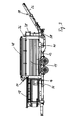
- Fig. 3 shows in side view a schematic schematic diagram of a device according to the invention 10 for cleaning plastic films according to Fig. 2 , As far as components too Fig. 1 or 2 correspond, the same reference numerals are chosen here.
- the device 10 is designed to be mobile by the carrier vehicle 13.
- a control mechanism 56 is below the funnel-shaped Recording 18 provided.
- the control mechanism 56 is used to control the rotational speed of the screen drum 14.
- the drive 16 is adjusted accordingly.
- the second conveyor belt 28 of the conveyor discharge device 26 is also clearly visible.
- the second conveyor belt 28 is pivotally and hingedly provided for the transport of the carrier vehicle 13.
Landscapes
- Separation, Recovery Or Treatment Of Waste Materials Containing Plastics (AREA)
- Cleaning By Liquid Or Steam (AREA)
Description
- Die Erfindung betrifft eine Einrichtung zur Reinigung von Kunststofffolien enthaltend:
- a) eine Vorrichtung mit einer rotierenden Siebtrommel, welche mit einem Antrieb angetrieben wird,
- b) eine Förderzufuhrvorrichtung, welche die schmutzige Folie in die Siebtrommel fördert,
- c) eine Wanne zur Aufnahme von Reinigungswasser,
- d) eine Förderabfuhrvorrichtung, welche die gereinigte Folie aus der Siebtrommel abtransportiert, und
- e) eine Wassereinspritzanlage, welche Wasser zur Reinigung der Folie in die Siebtrommel einspritzt, vorgesehen ist.
- Folien, vor allem Kunststofffolien, werden beispielsweise in großen Mengen bei der Erzeugung von Tomaten oder sonstigen Gemüse- und Obstproduktion verwendet. Diese Folien decken dabei große Landflächen ab, um die Früchte insbesondere vor Sonne zu schützen. Der Einsatz erfolgt verstärkt in wärmeren und sonnenintensiven Regionen. Diese Folien verschmutzen mit der Zeit durch unterschiedliche Umwelteinflüsse sehr stark. Entweder werden die stark verschmutzten Folien in großen Mengen entsorgt oder wieder recycelt.
- Im Fall des Recyclings werden die Folien zerkleinert, um aus ihnen ein Granulat herzustellen. Dieses Granulat wird anschließend wieder geschmolzen, um daraus erneut Folie zu erstellen. Problem bei dem Recycling ist die starke Verschmutzung.
- Die Folien werden deswegen vor dem Zerkleinern zu Granulat gereinigt. Dabei besteht das Problem, dass die Reinigung nicht hinreichend ist. Der an der Folie verbleibende Restschmutz fällt mit ins Granulat und beeinträchtigt dann die Herstellung einer neuen Folie. Die recycelte Folie ist daher von erheblich geringerer Qualität, was sich insbesondere dadurch bemerkbar macht, dass sie schneller reißt oder nicht ausreichend lichtdurchlässig ist.
- Es sind Vorrichtungen zum Reinigen der Folie bekannt, bei denen die Folien zerkleinert und mit Wasser gewaschen werden. Das Patent
DD 238 157 - Nachteil des beschriebenen Standes der Technik ist, dass die Reinigung nicht hinreichend ist, um die Folie, besonders vom groben Schmutz, zu reinigen. Der grobe Schmutz stört dabei insbesondere den Reinigungsprozess und die dazu erforderlichen Maschinen und sonstige Vorrichtungen, die dafür erforderlich sind.
- Die
AT 389 488 B - In der
DE 20 2009 005 033 U1 wird eine mobile Trommelsiebanordnung mit einer Waschtrommel und einer in Förderrichtung dahinter angeordneten Siebtrommel zum Reinigen und Sieben von Kies, Sand o.ä. beschrieben. Das zu reinigende Gut gelangt über eine Fördereinrichtung zunächst in die Waschtrommel und dann in die Siebtrommel. Bei der Siebtrommel ist eine zusätzliche Bedüsung zum Reinigen des Gutes vorgesehen. - Aufgabe der Erfindung ist es daher, die genannten Nachteile des Standes der Technik zu vermeiden und eine Einrichtung zur Reinigung von Kunststofffolien mit einer Siebtrommel zu schaffen, die besonders den groben Schmutz von der Folie entfernt und dabei ein Zusetzen von Sieböffnungen verhindert.
- Erfindungsgemäß wird die Aufgabe dadurch gelöst, dass bei einer Einrichtung zur Reinigung von Kunststofffolien der eingangs genannten Art
- f) eine Bürstenvorrichtung an der Siebtrommel vorgesehen ist.
- Die Erfindung beruht auf zwei wesentlichen mechanischen Reinigungseffekten: Der erste Effekt ist, dass die verschmutzte Folie in die Siebtrommel mittels Förderzufuhrvorrichtung gefördert und dort solange mit Wasser bespritzt wird, bis die Grobverschmutzung sich von der Folie löst. Der zweite Effekt besteht darin, dass durch Rotation der Siebtrommel die Folie kontinuierlich bewegt wird, so dass sie von allen Seiten mit dem Wasser bespritzt werden kann. Durch die Rotation reibt zudem die Siebtrommel mechanisch an der Folie und löst die Verschmutzung. Außerdem gibt es mechanische Reibungseffekte durch die geschleuderte Folie selbst. Diese Reinigungseffekte werden bisher mit keinem bekannten Verfahren erreicht. Es kann nun fast immer darauf verzichtet werden, dass dem Reinigungsprozess chemische Substanzen zugesetzt werden müssen. Das verschmutzte Wasser fließt durch das Sieb der Siebtrommel nach unten in eine Wanne. Nach dem vollständigen Reinigungsprozess wird die Folie aus der Siebtrommel mittels Förderabfuhrvorrichtung zur weiteren Behandlung oder Verarbeitung abtransportiert.
- Bei der erfindungsgemäßen Einrichtung zur Reinigung von Kunststofffolien ist eine Bürstenvorrichtung an der Siebtrommel vorgesehen. Bei dem Reinigungsprozess der Folie kann es zu einer nicht unerheblichen Verschmutzung der Siebtrommel kommen. Um diese Verschmutzung zu beseitigen bürstet die Bürstenvorrichtung die Verschmutzung während der Rotation der Siebtrommel mechanisch ab. Die Bürste ist dazu parallel zur Rotationsachse der Siebtrommel angeordnet. Gegebenenfalls besteht die Bürste aus einer zylindrischen Bürste, die selbst rotiert, um den mechanischen Reinigungsprozess der Siebtrommel zu erhöhen. Damit bleibt das Sieb der Siebtrommel frei von Verschmutzung. Die Verschmutzungsabfälle der Folie können somit immer ungehindert durch das Sieb der Siebtrommel in die Wanne gespült werden.
- Eine vorteilhafte Ausgestaltung der erfindungsgemäßen Einrichtung zur Reinigung von Kunststofffolien besteht darin, dass die Wanne zur Aufnahme von Reinigungswasser mit einer Wasseraufbereitungsanlage verbunden ist, welche von der Folie verschmutztes Wasser aufbereitet und der Wassereinspritzanlage zuführt. Aus ökologischen und ökonomischen Gründen ist es sinnvoll der Einrichtung nicht immer neues Wasser hinzuzuführen. Denn einerseits ist Wasser ein kostbares Gut, mit welchem sparsam umgegangen werden sollte, vor allem in Regionen mit nur wenigen Trinkwasserressourcen und andererseits treibt neues Wasser die Betriebskosten für ein Verfahren mit einer solchen Einrichtung in die Höhe. Zudem gelangt das verschmutzte Wasser nicht in die Natur. Insofern dient diese Ausgestaltung der Erfindung dazu, das benutzte Wasser in einem Wasserkreislauf der Einrichtung zu belassen. Die zu verwendende Wassermenge kann auf ein Optimum begrenzt werden.
- In einer bevorzugten Ausbildung der erfindungsgemäßen Einrichtung ist die Wanne zur Aufnahme von Reinigungswasser unterhalb der Siebtrommel angeordnet, wobei das Reinigungswasser in der Wanne mit der Siebtrommel nicht in Kontakt kommt. Bei einer Waschmaschine tauchen die Waschtrommel und damit auch die Wäsche in das Schmutzwasser ein. Damit wird gleichzeitig jedes Mal bereits im Wasser gelöste Schmutzpartikel wieder von der Wäsche aufgenommen, die durch zahlreiche Spülgänge erst wieder herausgewaschen werden. Diese vorliegende Maßnahme hat daher den Vorteil, dass die Folie ständig mit dem Wasser bespritzt und gereinigt wird, aber nicht mehr in verschmutztes Wasser eintaucht. Zusätzliche Spülgänge sind insofern unnötig und der Reinigungsprozess kann insofern beschleunigt werden.
- Eine weitere vorteilhafte Ausgestaltung der erfindungsgemäßen Einrichtung zur Reinigung von Kunststofffolien besteht in einer Zerkleinerungsanlage, welche die verschmutzte Folie für den Reinigungsprozess zerkleinert und der Förderzufuhrvorrichtung zuführt. Durch die Zerkleinerung wird die mit Wasser bespritzbare Oberfläche der Folie in der Siebtrommel optimiert. Außerdem wird schneller der Schmutz von der so vergrößerten Oberfläche aufgrund der erhöhten mechanischen Reibung gelöst. Weiterhin kann die zerkleinerte Folie leichter verarbeitet und insbesondere besser auf den Fördervorrichtungen transportiert werden. Kunststofffolie fällt üblicherweise nicht nur an einem Ort und zu jeder Zeit an. Jeder Gemüsebauer der beispielsweise verschmutzte Reste hat, müsste sich eigentlich eine solche Einrichtung zur Reinigung von Kunststofffolien hinstellen, um diese entsprechend zu verarbeiten. Hier ist in einer weiteren vorteilhaft Ausgestaltung der Erfindung daher vorgesehen, dass die Einrichtung zur Reinigung von Kunststofffolien mobil ausgebildet ist. Dazu ist die Einrichtung beispielsweise auf einem Trägerfahrzeug oder einem entsprechenden Anhänger aufgebaut. Die Einrichtung kann aufgrund ihrer Dimension dabei auch vorzugsweise modular auf mehreren Trägerfahrzeugen bzw. Anhängern vorgesehen sein. Damit kann die erfindungsgemäße Einrichtung an unterschiedlichen Orten eingesetzt werden. So können sich mehrere Gemüsebauern, um bei dem Beispiel zu bleiben, diese Einrichtung teilen indem sie von Gemüsebauer zu Gemüsebauer bewegt wird.
- Ein besonderer Aspekt der Erfindung ergibt sich zudem dadurch, dass eine Vorrichtung zum Zusetzen von Reinigungsadditiven in die Siebtrommel vorgesehen ist. Bei besonders verschmutzten Folien, beispielsweise verölte Folien, kann es erforderlich sein ein Lösungsmittel beizumischen, um diese von der Folie zu lösen. Hierfür ist die Vorrichtung zum Zusetzen von Additiven vorgesehen. Die Reinigungsadditive können separat der Folie zugeführt werden aber ggf. auch der Wassereinspritzanlage zugemischt werden. Sofern die Wasseraufbereitungsanlage in dem Reinigungsprozess integriert ist, bleibt diese Reinigungsadditiv im Kreislauf und gelangt nicht in die Umwelt.
- Um die Wirkung der Wassereinspritzanlage zu erhöhen, weist die Wassereinspritzanlage der erfindungsgemäßen Einrichtung zur Reinigung von Kunststofffolien Mittel zum Einspritzen des Wassers in die Siebtrommel mir Hochdruck auf. Der erhöhte Wasserdruck löst die Schmutzpartikel besonders gut von der Folie ab. Vorzugsweise kommt das Wasser aus mehreren Düsen, so dass die Folie von vielen Seiten zur mechanischen Reinigung bearbeitet wird. Der Reinigungsprozess wird durch diese Maßnahme erheblich optimiert.
- In einer bevorzugten Ausbildung der erfindungsgemäßen Einrichtung zur Reinigung von Kunststofffolien weist die Siebtrommel an ihrer Innenseite eine schneckenförmige Leiste auf. Durch die schneckenförmig angeordnete Leiste auf der Innenseite der Siebtrommel wird die Folie innerhalb der Siebtrommel besser transportiert und durchmischt.
- Je nach Befüllungsgrad mit Folie kann es vorteilhaft sein, die Rotationsgeschwindigkeit der Siebtrommel anzupassen, um den Reinigungsprozess zu optimieren. In einer vorteilhaften Ausbildung der Erfindung ist daher ein Regelmechanismus zur Regelung der Rotationsgeschwindigkeit der Siebtrommel vorgesehen.
- Weitere Ausgestaltungen und Vorteile der Erfindung ergeben sich aus dem Gegenstand der Unteransprüche. Ein Ausführungsbeispiel ist nachstehend unter Bezugnahme auf die beigefügten Zeichnungen näher erläutert.
-
- Fig. 1
- zeigt in einer perspektivischen Prinzipskizze eine erfindungsgemäße Einrichtung zur Reinigung von Kunststofffolien mit Wasseraufbereitungsanlage.
- Fig. 2
- zeigt in einer perspektivischen Prinzipskizze eine erfindungsgemäße Einrichtung zur Reinigung von Kunststofffolien
- Fig. 3
- zeigt in Seitendarstellung eine schematische Prinzipskizze einer erfindungsgemäßen Einrichtung zur Reinigung von Kunststofffolien gemäß
Fig. 2 . - In
Fig. 1 wird eine Einrichtung 10 zur Reinigung von verschmutzten Kunststofffolien schematisch dargestellt. Die Einrichtung 10 enthält eine Vorrichtung 12 mit einer rotierenden Siebtrommel 14. Die Vorrichtung 12 befindet sich auf einem mobilen Trägerfahrzeug 13. Ein Antrieb 16 treibt hierzu die Siebtrommel 14 an. Der Durchmesser der Sieböffnungen ist dabei so ausgelegt, dass eine Verschmutzung der Kunststofffolien dort hindurchtreten kann. Zur Befüllung wird die Kunststofffolie in eine trichterförmige Aufnahme 18 geladen. Die trichterförmige Aufnahme 18 befindet sich an einer ersten Stirnseite 20 der Siebtrommel 14. Unterhalb der trichterförmigen Aufnahme 18 ist eine Förderzufuhrvorrichtung 22 angeordnet. Die Förderzufuhrvorrichtung 22 enthält ein erstes Förderband 24, welches die Kunststofffolie in die Siebtrommel 14 befördert. - Nach der Reinigung wird die Kunststofffolie über eine Förderabfuhreinrichtung 26 aus der Siebtrommel herausbefördert. Die Förderabfuhreinrichtung 26 enthält ebenfalls ein zweites Förderband 28, welches die gereinigte Kunststofffolie zu einem Transportsystem 30 mit mehreren Transportbändern 32 fördert. Das Transportsystem 30 leitet die gereinigte Kunststofffolie in Sammelbehälter 34. Von dort kann die Kunststofffolie zur Weiterverarbeitung abtransportiert werden.
- An einer zweiten Stirnseite 36 der Siebtrommel 14 ist eine Wassereinspritzanlage 38 angeordnet. Mehrere Wasserdüsen 40 leiten das Wasser in die Siebtrommel 14 ein. Während die Siebtrommel 14 sich dreht, wird die Kunststofffolie gut durchmischt. Alle Seiten der Kunststofffolie werden gut bespritzt.
- Unterhalb der Siebtrommel 14 ist eine Wanne 42 angeordnet. Die Wanne 42 ist eine Auffangwanne, welche das Reinigungswasser mit den abgelösten Schmutzpartikeln auffängt. Die Wanne 42 ist beabstandet unterhalb der Siebtrommel 14 angeordnet, damit sie nicht, auch nicht zumindest teilweise, mit dem Reinigungswasser in Kontakt kommt. Das Reinigungswasser wird zu einer Wasseraufbereitungsanlage 44 gepumpt. Nach der Wasseraufbereitung bezieht die Wassereinspritzanlage 38 das Wasser von der Wasseraufbereitungsanlage 44. Das in der Einrichtung 10 verwendete Wasser verbleibt so in einem Wasserkreislauf.
- Zur Aufbereitung der Kunststofffolie, bevor sie in die trichterförmigen Aufnahme 18 gelangt, wird die Folie in einer Zerkleinerungsanlage 46 in ausreichendem Maße zerkleinert. Dabei darf die Folie nicht in zu kleine Bestandteile zerlegt werden, damit sie nicht durch die Sieböffnungen gelangen kann. Von der Zerkleinerungsanlage 46 wird die zerkleinerte Kunststofffolie in die trichterförmige Aufnahme 18 befördert.
- In
Fig. 2 ist in einer perspektivischen Prinzipskizze die Vorrichtung 12 mit der mobilen Siebtrommel 14 dargestellt. Soweit sich Bestandteile zuFig.1 entsprechen, sind auch dieselben Bezugszeichen hier gewählt. Die Vorrichtung 12 ist auf dem mobilen Trägerfahrzeug 13 montiert. Die Kunststofffolie wird in die trichterförmige Aufnahme 18 gegeben. Die Förderzufuhrvorrichtung 22 mit dem ersten Förderband 24 transportiert die zerkleinerte Folie in die rotierende Siebtrommel 14. Der Antrieb 16 treibt die Siebtrommel 14 zu einer Rotationsbewegung an. Die Siebtrommel 14 ist entsprechend in der Vorrichtung 12 gelagert. Unterhalb der Siebtrommel 14 ist die Wanne 42. Die Wanne 42 fängt das schmutzige und verbrauchte Reinigungswasser auf. Oberhalb der Siebtrommel 14 ist eine Bürstenvorrichtung 48 vorgesehen. Die Bürstenvorrichtung 48 weist Bürsten 50 auf, die sich parallel zur Rotationsachse und entlang der Siebtrommel 14 erstrecken. Die Bürsten 50 bürsten insbesondere die Verunreinigungen auf der Siebtrommel 14 ab, womit insbesondere gewährleistet wird, dass die Sieböffnungen sich nicht zusetzen. - Auf Innenwand 52 der Siebtrommel 14 ist eine schneckenförmige Leiste 54 befestigt. Die schneckenförmige Leiste 54 unterstützt den Reinigungsprozess innerhalb der Siebtrommel 14 und gibt dem Folienmaterial zudem eine Förderrichtung durch die Siebtrommel 14. Die Anordnung der schneckenförmigen Leiste 54 und die Rotationsrichtung der Siebtrommel 14 sind nämlich so ausgewählt, dass die Folie nur in eine Richtung geführt wird. Die Wassereinspritzanlage 38 ragt lanzenartig und relativ zentral in die Siebtrommel 14. Die Wassereinspritzanlage 38 bespritzt die Folie durch mehrere der Wasserdüsen 40 weitestgehend radial. Das Wasser wird dabei mit Hochdruck in die Düsen geleitet. Den Druck liefert hierzu ein Hochdruckgenerator 41.
- An der zweiten Stirnseite 36 der Siebtrommel 14 wird die gereinigte Kunststofffolie mit der Förderabfuhrvorrichtung 26 abtransportiert.
-
Fig. 3 zeigt in Seitendarstellung eine schematische Prinzipskizze einer erfindungsgemäßen Einrichtung 10 zur Reinigung von Kunststofffolien gemäßFig. 2 . Soweit sich Bestandteile zuFig. 1 oder2 entsprechen, sind auch hier dieselben Bezugszeichen gewählt. Die Einrichtung 10 ist durch das Trägerfahrzeug 13 mobil ausgelegt. In dieser Ansicht ist ein Regelmechanismus 56 unterhalb der trichterförmigen Aufnahme 18 vorgesehen. Der Regelmechanismus 56 dient zur Regelung der Rotationsgeschwindigkeit der Siebtrommel 14. Dazu wird der Antrieb 16 entsprechend eingestellt. Aus dieser Perspektive ist ferner das zweite Förderband 28 der Förderabfuhreinrichtung 26 gut zu sehen. Das zweite Förderband 28 ist schwenk- und klappbar für den Transport des Trägerfahrzeugs 13 vorgesehen. - Eine Vorrichtung 58 zum Zusetzen von Reinigungsadditiven in die Siebtrommel 14 fügt bei Bedarf z.B. Lösungsmittel dem Wasser zu, welches auf die verschmutzte Kunststofffolie mittels der Wassereinspritzanlage 38 gespritzt wird.
- 10
- Einrichtung zur Reinigung von Kunststofffolien
- 12
- Vorrichtung
- 13
- Trägerfahrzeug
- 14
- Siebtrommel
- 16
- Antrieb
- 18
- trichterförmige Aufnahme
- 20
- erste Stirnseite der Siebtrommel
- 22
- Förderzufuhrvorrichtung
- 24
- erstes Förderband
- 26
- Förderabfuhreinrichtung
- 28
- zweites Förderband
- 30
- Transportsystem
- 32
- Transportbänder
- 34
- Sammelbehälter
- 36
- zweite Stirnseite der Siebtrommel
- 38
- Wassereinspritzanlage
- 40
- Wasserdüsen
- 41
- Hochdruckgenerator
- 42
- Wanne
- 44
- Wasseraufbereitungsanlage
- 46
- Zerkleinerungsanlage
- 48
- Bürstenvorrichtung
- 50
- Bürsten
- 52
- Innenwand
- 54
- schneckenförmige Leiste
- 56
- Regelmechanismus
- 58
- Vorrichtung zum Zusetzen von Reinigungsadditiven
Claims (9)
- Einrichtung (10) zur Reinigung von Kunststofffolien enthaltend:a) eine Vorrichtung (12) mit einer rotierenden Siebtrommel (14), welche mit einem Antrieb (16) angetrieben wird,b) eine Förderzufuhrvorrichtung (22), welche die schmutzige Folie in die Siebtrommel (14) fördert,c) eine Wanne (42) zur Aufnahme von Reinigungswasser,d) eine Förderabfuhrvorrichtung (26), welche die gereinigte Folie aus der Siebtrommel (14) abtransportiert,e) eine Wassereinspritzanlage (38), welche Wasser zur Reinigung der Folie
in die Siebtrommel (14) einspritzt,
dadurch gekennzeichnet, dassf) eine Bürstenvorrichtung (48) an der Siebtrommel (14) vorgesehen ist. - Einrichtung (10) zur Reinigung von Kunststofffolien nach Anspruch 1, dadurch gekennzeichnet, dass die Wanne (42) zur Aufnahme von Reinigungswasser mit einer Wasseraufbereitungsanlage (44) verbunden ist, welche von der Folie verschmutztes Wasser aufbereitet und der Wassereinspritzanlage (38) zuführt.
- Einrichtung (10) zur Reinigung von Kunststofffolien nach einem der Ansprüche 1 oder 2, dadurch gekennzeichnet, dass die Wanne (42) zur Aufnahme von Reinigungswasser unterhalb der Siebtrommel (14) angeordnet ist, wobei das Reinigungswasser in der Wanne (42) mit der Siebtrommel (14) nicht in Kontakt kommt.
- Einrichtung (10) zur Reinigung von Kunststofffolien nach einem der Ansprüche 1 bis 3, gekennzeichnet durch eine Zerkleinerungsanlage (46), welche die die verschmutzte Folie für den Reinigungsprozess zerkleinert und der Förderzufuhrvorrichtung (22) zuführt.
- Einrichtung (10) zur Reinigung von Kunststofffolien nach einem der Ansprüche 1 bis 4, dadurch gekennzeichnet, dass die Einrichtung (10) mobil ausgebildet ist.
- Einrichtung (10) zur Reinigung von Kunststofffolien nach einem der Ansprüche 1 bis 5, dadurch gekennzeichnet, dass eine Vorrichtung (58) zum Zusetzen von Reinigungsadditiven in die Siebtrommel (14) vorgesehen ist.
- Einrichtung (10) zur Reinigung von Kunststofffolien nach einem der Ansprüche 1 bis 6, dadurch gekennzeichnet, dass die Wassereinspritzanlage (38) Mittel (41) zum Einspritzen des Wassers in die Siebtrommel (14) mit Hochdruck aufweist.
- Einrichtung (10) zur Reinigung von Kunststofffolien nach einem der Ansprüche 1 bis 7, dadurch gekennzeichnet, dass die Siebtrommel (14) an ihrer Innenseite eine schneckenförmige Leiste (54) aufweist.
- Einrichtung (10) zur Reinigung von Kunststofffolien nach einem der Ansprüche 1 bis 8, dadurch gekennzeichnet, dass ein Regelmechanismus (56) zur Regelung der Rotationsgeschwindigkeit der Siebtrommel (14) vorgesehen ist.
Priority Applications (1)
| Application Number | Priority Date | Filing Date | Title |
|---|---|---|---|
| PL12171727T PL2548661T3 (pl) | 2011-07-18 | 2012-06-13 | Urządzenie do oczyszczania folii |
Applications Claiming Priority (1)
| Application Number | Priority Date | Filing Date | Title |
|---|---|---|---|
| DE102011051917A DE102011051917A1 (de) | 2011-07-18 | 2011-07-18 | Folienreinigungsvorrichtung |
Publications (2)
| Publication Number | Publication Date |
|---|---|
| EP2548661A1 EP2548661A1 (de) | 2013-01-23 |
| EP2548661B1 true EP2548661B1 (de) | 2013-12-25 |
Family
ID=46261963
Family Applications (1)
| Application Number | Title | Priority Date | Filing Date |
|---|---|---|---|
| EP12171727.6A Not-in-force EP2548661B1 (de) | 2011-07-18 | 2012-06-13 | Folienreinigungsvorrichtung |
Country Status (3)
| Country | Link |
|---|---|
| EP (1) | EP2548661B1 (de) |
| DE (1) | DE102011051917A1 (de) |
| PL (1) | PL2548661T3 (de) |
Families Citing this family (2)
| Publication number | Priority date | Publication date | Assignee | Title |
|---|---|---|---|---|
| CN109013444A (zh) * | 2018-07-11 | 2018-12-18 | 甘灿琼 | 一种搅拌及摆动式中药碎块多级清洗装置 |
| CN119608564A (zh) * | 2024-12-30 | 2025-03-14 | 河北橡一医药科技股份有限公司 | 筛分清洗装置 |
Family Cites Families (4)
| Publication number | Priority date | Publication date | Assignee | Title |
|---|---|---|---|---|
| US3944189A (en) * | 1973-11-28 | 1976-03-16 | Albert Singleton | Door opening and closing apparatus for tumbling barrel |
| DD238157A3 (de) | 1984-04-27 | 1986-08-13 | Wolfen Filmfab Veb | Verfahren zur rueckgewinnung von folienabfaellen |
| AT389488B (de) * | 1987-11-23 | 1989-12-11 | Andritz Ag Maschf | Verfahren und anordnung zur reinigung von vorzugsweise zerkleinerte kunststofffolien und bzw. oder kunststoffstuecke und bzw. oder hartkunststoffe od.dgl. enthaltenden substraten |
| DE202009005033U1 (de) * | 2009-07-16 | 2009-12-31 | Doppstadt, Ferdinand | Siebanordnung |
-
2011
- 2011-07-18 DE DE102011051917A patent/DE102011051917A1/de not_active Withdrawn
-
2012
- 2012-06-13 EP EP12171727.6A patent/EP2548661B1/de not_active Not-in-force
- 2012-06-13 PL PL12171727T patent/PL2548661T3/pl unknown
Also Published As
| Publication number | Publication date |
|---|---|
| PL2548661T3 (pl) | 2014-05-30 |
| DE102011051917A1 (de) | 2013-01-24 |
| EP2548661A1 (de) | 2013-01-23 |
Similar Documents
| Publication | Publication Date | Title |
|---|---|---|
| EP2052791B1 (de) | Vorrichtung und verfahren zur reinigung von schüttgut | |
| EP2292340B1 (de) | Verfahren zum Reinigen von Behältern und Reinigungsmaschine | |
| EP2830407B1 (de) | Vorrichtung zur reinigung von feldfrüchten | |
| DE60103253T2 (de) | Reinigen von oberflächen | |
| DE4042167C2 (de) | ||
| DE102011110994B4 (de) | Vorrichtung zur Aufbereitung von landwirtschaftlichem Erntegut als Aufgabematerial in einem Bioreaktor | |
| EP1920853B1 (de) | Vorrichtung zum Behandeln von Werkstücken oder dergleichen | |
| EP2012901A1 (de) | Verfahren und vorrichtung zum abtrennen grober feststoffe aus einem viskosen fluid | |
| DE102013014312B3 (de) | Reinigungseinheit und Verfahren zur Grundreinigung von Hallenböden | |
| EP2817131A1 (de) | Verfahren und anordnung zum recyclen von klebstoffbehafteten folienresten | |
| EP2548661A1 (de) | Folienreinigungsvorrichtung | |
| DE10060173B4 (de) | Vorrichtung zum Aufbereiten eines Sandgemisches in eine Fein- und eine Grobfraktion | |
| EP2500459B1 (de) | Verfahren und Vorrichtung zum Waschen von insbesondere Wäschestücken | |
| DE102005014684A1 (de) | Verfahren und Vorrichtung zum Entgraten von kleinen Formteilen | |
| EP2982426A1 (de) | Siebeinrichtung, Verfahren zu deren Betrieb und Verwendung | |
| DE4114780A1 (de) | Muellverwertungsverfahren und -einrichtung zum trennen von haerteren und weicheren muellbestandteilen | |
| DE2806126A1 (de) | Reinigungsvorrichtung | |
| AT389488B (de) | Verfahren und anordnung zur reinigung von vorzugsweise zerkleinerte kunststofffolien und bzw. oder kunststoffstuecke und bzw. oder hartkunststoffe od.dgl. enthaltenden substraten | |
| DE3824009C2 (de) | Verfahren zum Entfernen wenig wasserlöslicher Schadflüssigkeiten aus schweren Böden und Vorrichtung zur Durchführung des Verfahrens | |
| DE102007027400A1 (de) | Verfahren und Vorrichtung zum Aufbereiten von gebrochenem Altglas mit anhaftenden Verunreinigungen | |
| DE4321795C2 (de) | Verfahren und Vorrichtung zur Reinigung von schüttfähigen Materialien | |
| DE2212251B2 (de) | Vorrichtung zum Zerkleinern von in Rohkies enthaltenen, klumpenförmigen Fremdstoffen | |
| EP0476464B1 (de) | Verfahren und Vorrichtung zum Abscheiden gasgetragener, in Flüssigkeiten löslicher Partikel | |
| DE102015012354A1 (de) | Vorrichtung zum Waschen von kleinstückigem Material | |
| DE102015007912A1 (de) | Vorrichtung und Verfahren zum Behandeln von insbesondere kleinstückigem Schüttgut |
Legal Events
| Date | Code | Title | Description |
|---|---|---|---|
| PUAI | Public reference made under article 153(3) epc to a published international application that has entered the european phase |
Free format text: ORIGINAL CODE: 0009012 |
|
| AK | Designated contracting states |
Kind code of ref document: A1 Designated state(s): AL AT BE BG CH CY CZ DE DK EE ES FI FR GB GR HR HU IE IS IT LI LT LU LV MC MK MT NL NO PL PT RO RS SE SI SK SM TR |
|
| AX | Request for extension of the european patent |
Extension state: BA ME |
|
| 17P | Request for examination filed |
Effective date: 20130710 |
|
| RBV | Designated contracting states (corrected) |
Designated state(s): AL AT BE BG CH CY CZ DE DK EE ES FI FR GB GR HR HU IE IS IT LI LT LU LV MC MK MT NL NO PL PT RO RS SE SI SK SM TR |
|
| GRAP | Despatch of communication of intention to grant a patent |
Free format text: ORIGINAL CODE: EPIDOSNIGR1 |
|
| INTG | Intention to grant announced |
Effective date: 20131011 |
|
| GRAS | Grant fee paid |
Free format text: ORIGINAL CODE: EPIDOSNIGR3 |
|
| GRAA | (expected) grant |
Free format text: ORIGINAL CODE: 0009210 |
|
| AK | Designated contracting states |
Kind code of ref document: B1 Designated state(s): AL AT BE BG CH CY CZ DE DK EE ES FI FR GB GR HR HU IE IS IT LI LT LU LV MC MK MT NL NO PL PT RO RS SE SI SK SM TR |
|
| REG | Reference to a national code |
Ref country code: GB Ref legal event code: FG4D Free format text: NOT ENGLISH |
|
| REG | Reference to a national code |
Ref country code: CH Ref legal event code: EP |
|
| REG | Reference to a national code |
Ref country code: AT Ref legal event code: REF Ref document number: 646303 Country of ref document: AT Kind code of ref document: T Effective date: 20140115 |
|
| REG | Reference to a national code |
Ref country code: IE Ref legal event code: FG4D Free format text: LANGUAGE OF EP DOCUMENT: GERMAN |
|
| REG | Reference to a national code |
Ref country code: DE Ref legal event code: R096 Ref document number: 502012000290 Country of ref document: DE Effective date: 20140213 |
|
| REG | Reference to a national code |
Ref country code: NL Ref legal event code: T3 |
|
| PG25 | Lapsed in a contracting state [announced via postgrant information from national office to epo] |
Ref country code: FI Free format text: LAPSE BECAUSE OF FAILURE TO SUBMIT A TRANSLATION OF THE DESCRIPTION OR TO PAY THE FEE WITHIN THE PRESCRIBED TIME-LIMIT Effective date: 20131225 Ref country code: HR Free format text: LAPSE BECAUSE OF FAILURE TO SUBMIT A TRANSLATION OF THE DESCRIPTION OR TO PAY THE FEE WITHIN THE PRESCRIBED TIME-LIMIT Effective date: 20131225 Ref country code: NO Free format text: LAPSE BECAUSE OF FAILURE TO SUBMIT A TRANSLATION OF THE DESCRIPTION OR TO PAY THE FEE WITHIN THE PRESCRIBED TIME-LIMIT Effective date: 20140325 Ref country code: SE Free format text: LAPSE BECAUSE OF FAILURE TO SUBMIT A TRANSLATION OF THE DESCRIPTION OR TO PAY THE FEE WITHIN THE PRESCRIBED TIME-LIMIT Effective date: 20131225 Ref country code: LT Free format text: LAPSE BECAUSE OF FAILURE TO SUBMIT A TRANSLATION OF THE DESCRIPTION OR TO PAY THE FEE WITHIN THE PRESCRIBED TIME-LIMIT Effective date: 20131225 |
|
| REG | Reference to a national code |
Ref country code: LT Ref legal event code: MG4D |
|
| PG25 | Lapsed in a contracting state [announced via postgrant information from national office to epo] |
Ref country code: LV Free format text: LAPSE BECAUSE OF FAILURE TO SUBMIT A TRANSLATION OF THE DESCRIPTION OR TO PAY THE FEE WITHIN THE PRESCRIBED TIME-LIMIT Effective date: 20131225 Ref country code: RS Free format text: LAPSE BECAUSE OF FAILURE TO SUBMIT A TRANSLATION OF THE DESCRIPTION OR TO PAY THE FEE WITHIN THE PRESCRIBED TIME-LIMIT Effective date: 20131225 |
|
| REG | Reference to a national code |
Ref country code: PL Ref legal event code: T3 |
|
| PG25 | Lapsed in a contracting state [announced via postgrant information from national office to epo] |
Ref country code: EE Free format text: LAPSE BECAUSE OF FAILURE TO SUBMIT A TRANSLATION OF THE DESCRIPTION OR TO PAY THE FEE WITHIN THE PRESCRIBED TIME-LIMIT Effective date: 20131225 Ref country code: IS Free format text: LAPSE BECAUSE OF FAILURE TO SUBMIT A TRANSLATION OF THE DESCRIPTION OR TO PAY THE FEE WITHIN THE PRESCRIBED TIME-LIMIT Effective date: 20140425 |
|
| PG25 | Lapsed in a contracting state [announced via postgrant information from national office to epo] |
Ref country code: ES Free format text: LAPSE BECAUSE OF FAILURE TO SUBMIT A TRANSLATION OF THE DESCRIPTION OR TO PAY THE FEE WITHIN THE PRESCRIBED TIME-LIMIT Effective date: 20131225 Ref country code: CY Free format text: LAPSE BECAUSE OF FAILURE TO SUBMIT A TRANSLATION OF THE DESCRIPTION OR TO PAY THE FEE WITHIN THE PRESCRIBED TIME-LIMIT Effective date: 20131225 Ref country code: CZ Free format text: LAPSE BECAUSE OF FAILURE TO SUBMIT A TRANSLATION OF THE DESCRIPTION OR TO PAY THE FEE WITHIN THE PRESCRIBED TIME-LIMIT Effective date: 20131225 Ref country code: RO Free format text: LAPSE BECAUSE OF FAILURE TO SUBMIT A TRANSLATION OF THE DESCRIPTION OR TO PAY THE FEE WITHIN THE PRESCRIBED TIME-LIMIT Effective date: 20131225 Ref country code: PT Free format text: LAPSE BECAUSE OF FAILURE TO SUBMIT A TRANSLATION OF THE DESCRIPTION OR TO PAY THE FEE WITHIN THE PRESCRIBED TIME-LIMIT Effective date: 20140428 Ref country code: SK Free format text: LAPSE BECAUSE OF FAILURE TO SUBMIT A TRANSLATION OF THE DESCRIPTION OR TO PAY THE FEE WITHIN THE PRESCRIBED TIME-LIMIT Effective date: 20131225 |
|
| REG | Reference to a national code |
Ref country code: DE Ref legal event code: R097 Ref document number: 502012000290 Country of ref document: DE |
|
| PG25 | Lapsed in a contracting state [announced via postgrant information from national office to epo] |
Ref country code: DK Free format text: LAPSE BECAUSE OF FAILURE TO SUBMIT A TRANSLATION OF THE DESCRIPTION OR TO PAY THE FEE WITHIN THE PRESCRIBED TIME-LIMIT Effective date: 20131225 |
|
| PLBE | No opposition filed within time limit |
Free format text: ORIGINAL CODE: 0009261 |
|
| STAA | Information on the status of an ep patent application or granted ep patent |
Free format text: STATUS: NO OPPOSITION FILED WITHIN TIME LIMIT |
|
| 26N | No opposition filed |
Effective date: 20140926 |
|
| REG | Reference to a national code |
Ref country code: DE Ref legal event code: R097 Ref document number: 502012000290 Country of ref document: DE Effective date: 20140926 |
|
| PG25 | Lapsed in a contracting state [announced via postgrant information from national office to epo] |
Ref country code: LU Free format text: LAPSE BECAUSE OF FAILURE TO SUBMIT A TRANSLATION OF THE DESCRIPTION OR TO PAY THE FEE WITHIN THE PRESCRIBED TIME-LIMIT Effective date: 20140613 Ref country code: MC Free format text: LAPSE BECAUSE OF FAILURE TO SUBMIT A TRANSLATION OF THE DESCRIPTION OR TO PAY THE FEE WITHIN THE PRESCRIBED TIME-LIMIT Effective date: 20131225 |
|
| REG | Reference to a national code |
Ref country code: IE Ref legal event code: MM4A |
|
| PG25 | Lapsed in a contracting state [announced via postgrant information from national office to epo] |
Ref country code: IE Free format text: LAPSE BECAUSE OF NON-PAYMENT OF DUE FEES Effective date: 20140613 |
|
| PG25 | Lapsed in a contracting state [announced via postgrant information from national office to epo] |
Ref country code: SI Free format text: LAPSE BECAUSE OF FAILURE TO SUBMIT A TRANSLATION OF THE DESCRIPTION OR TO PAY THE FEE WITHIN THE PRESCRIBED TIME-LIMIT Effective date: 20131225 |
|
| REG | Reference to a national code |
Ref country code: CH Ref legal event code: PL |
|
| PG25 | Lapsed in a contracting state [announced via postgrant information from national office to epo] |
Ref country code: MT Free format text: LAPSE BECAUSE OF FAILURE TO SUBMIT A TRANSLATION OF THE DESCRIPTION OR TO PAY THE FEE WITHIN THE PRESCRIBED TIME-LIMIT Effective date: 20131225 |
|
| PG25 | Lapsed in a contracting state [announced via postgrant information from national office to epo] |
Ref country code: SM Free format text: LAPSE BECAUSE OF FAILURE TO SUBMIT A TRANSLATION OF THE DESCRIPTION OR TO PAY THE FEE WITHIN THE PRESCRIBED TIME-LIMIT Effective date: 20131225 Ref country code: CH Free format text: LAPSE BECAUSE OF NON-PAYMENT OF DUE FEES Effective date: 20150630 Ref country code: LI Free format text: LAPSE BECAUSE OF NON-PAYMENT OF DUE FEES Effective date: 20150630 |
|
| REG | Reference to a national code |
Ref country code: FR Ref legal event code: PLFP Year of fee payment: 5 |
|
| PG25 | Lapsed in a contracting state [announced via postgrant information from national office to epo] |
Ref country code: IT Free format text: LAPSE BECAUSE OF FAILURE TO SUBMIT A TRANSLATION OF THE DESCRIPTION OR TO PAY THE FEE WITHIN THE PRESCRIBED TIME-LIMIT Effective date: 20131225 Ref country code: BG Free format text: LAPSE BECAUSE OF FAILURE TO SUBMIT A TRANSLATION OF THE DESCRIPTION OR TO PAY THE FEE WITHIN THE PRESCRIBED TIME-LIMIT Effective date: 20131225 Ref country code: GR Free format text: LAPSE BECAUSE OF FAILURE TO SUBMIT A TRANSLATION OF THE DESCRIPTION OR TO PAY THE FEE WITHIN THE PRESCRIBED TIME-LIMIT Effective date: 20140326 |
|
| PG25 | Lapsed in a contracting state [announced via postgrant information from national office to epo] |
Ref country code: HU Free format text: LAPSE BECAUSE OF FAILURE TO SUBMIT A TRANSLATION OF THE DESCRIPTION OR TO PAY THE FEE WITHIN THE PRESCRIBED TIME-LIMIT; INVALID AB INITIO Effective date: 20120613 Ref country code: TR Free format text: LAPSE BECAUSE OF FAILURE TO SUBMIT A TRANSLATION OF THE DESCRIPTION OR TO PAY THE FEE WITHIN THE PRESCRIBED TIME-LIMIT Effective date: 20131225 |
|
| REG | Reference to a national code |
Ref country code: FR Ref legal event code: PLFP Year of fee payment: 6 |
|
| REG | Reference to a national code |
Ref country code: FR Ref legal event code: PLFP Year of fee payment: 7 |
|
| PG25 | Lapsed in a contracting state [announced via postgrant information from national office to epo] |
Ref country code: MK Free format text: LAPSE BECAUSE OF FAILURE TO SUBMIT A TRANSLATION OF THE DESCRIPTION OR TO PAY THE FEE WITHIN THE PRESCRIBED TIME-LIMIT Effective date: 20131225 |
|
| PG25 | Lapsed in a contracting state [announced via postgrant information from national office to epo] |
Ref country code: AL Free format text: LAPSE BECAUSE OF FAILURE TO SUBMIT A TRANSLATION OF THE DESCRIPTION OR TO PAY THE FEE WITHIN THE PRESCRIBED TIME-LIMIT Effective date: 20131225 |
|
| PGFP | Annual fee paid to national office [announced via postgrant information from national office to epo] |
Ref country code: FR Payment date: 20200623 Year of fee payment: 9 |
|
| PGFP | Annual fee paid to national office [announced via postgrant information from national office to epo] |
Ref country code: GB Payment date: 20200625 Year of fee payment: 9 Ref country code: PL Payment date: 20200603 Year of fee payment: 9 Ref country code: NL Payment date: 20200622 Year of fee payment: 9 Ref country code: BE Payment date: 20200622 Year of fee payment: 9 |
|
| PGFP | Annual fee paid to national office [announced via postgrant information from national office to epo] |
Ref country code: AT Payment date: 20200618 Year of fee payment: 9 |
|
| PGFP | Annual fee paid to national office [announced via postgrant information from national office to epo] |
Ref country code: DE Payment date: 20200819 Year of fee payment: 9 |
|
| REG | Reference to a national code |
Ref country code: DE Ref legal event code: R119 Ref document number: 502012000290 Country of ref document: DE |
|
| REG | Reference to a national code |
Ref country code: NL Ref legal event code: MM Effective date: 20210701 |
|
| REG | Reference to a national code |
Ref country code: AT Ref legal event code: MM01 Ref document number: 646303 Country of ref document: AT Kind code of ref document: T Effective date: 20210613 |
|
| GBPC | Gb: european patent ceased through non-payment of renewal fee |
Effective date: 20210613 |
|
| REG | Reference to a national code |
Ref country code: BE Ref legal event code: MM Effective date: 20210630 |
|
| PG25 | Lapsed in a contracting state [announced via postgrant information from national office to epo] |
Ref country code: GB Free format text: LAPSE BECAUSE OF NON-PAYMENT OF DUE FEES Effective date: 20210613 Ref country code: DE Free format text: LAPSE BECAUSE OF NON-PAYMENT OF DUE FEES Effective date: 20220101 Ref country code: AT Free format text: LAPSE BECAUSE OF NON-PAYMENT OF DUE FEES Effective date: 20210613 |
|
| PG25 | Lapsed in a contracting state [announced via postgrant information from national office to epo] |
Ref country code: NL Free format text: LAPSE BECAUSE OF NON-PAYMENT OF DUE FEES Effective date: 20210701 Ref country code: FR Free format text: LAPSE BECAUSE OF NON-PAYMENT OF DUE FEES Effective date: 20210630 |
|
| PG25 | Lapsed in a contracting state [announced via postgrant information from national office to epo] |
Ref country code: BE Free format text: LAPSE BECAUSE OF NON-PAYMENT OF DUE FEES Effective date: 20210630 |
|
| PG25 | Lapsed in a contracting state [announced via postgrant information from national office to epo] |
Ref country code: PL Free format text: LAPSE BECAUSE OF NON-PAYMENT OF DUE FEES Effective date: 20210613 |