EP2547838B1 - Device for simultaneous attachment and folding of brackets for roofing sheet - Google Patents
Device for simultaneous attachment and folding of brackets for roofing sheet Download PDFInfo
- Publication number
- EP2547838B1 EP2547838B1 EP11756636.4A EP11756636A EP2547838B1 EP 2547838 B1 EP2547838 B1 EP 2547838B1 EP 11756636 A EP11756636 A EP 11756636A EP 2547838 B1 EP2547838 B1 EP 2547838B1
- Authority
- EP
- European Patent Office
- Prior art keywords
- folding
- bracket
- housing
- arm
- folding device
- Prior art date
- Legal status (The legal status is an assumption and is not a legal conclusion. Google has not performed a legal analysis and makes no representation as to the accuracy of the status listed.)
- Active
Links
Images

Classifications
-
- E—FIXED CONSTRUCTIONS
- E04—BUILDING
- E04D—ROOF COVERINGS; SKY-LIGHTS; GUTTERS; ROOF-WORKING TOOLS
- E04D3/00—Roof covering by making use of flat or curved slabs or stiff sheets
- E04D3/36—Connecting; Fastening
- E04D3/361—Connecting; Fastening by specially-profiled marginal portions of the slabs or sheets
- E04D3/362—Connecting; Fastening by specially-profiled marginal portions of the slabs or sheets by locking the edge of one slab or sheet within the profiled marginal portion of the adjacent slab or sheet, e.g. using separate connecting elements
-
- E—FIXED CONSTRUCTIONS
- E04—BUILDING
- E04D—ROOF COVERINGS; SKY-LIGHTS; GUTTERS; ROOF-WORKING TOOLS
- E04D15/00—Apparatus or tools for roof working
- E04D15/04—Apparatus or tools for roof working for roof coverings comprising slabs, sheets or flexible material
-
- Y—GENERAL TAGGING OF NEW TECHNOLOGICAL DEVELOPMENTS; GENERAL TAGGING OF CROSS-SECTIONAL TECHNOLOGIES SPANNING OVER SEVERAL SECTIONS OF THE IPC; TECHNICAL SUBJECTS COVERED BY FORMER USPC CROSS-REFERENCE ART COLLECTIONS [XRACs] AND DIGESTS
- Y10—TECHNICAL SUBJECTS COVERED BY FORMER USPC
- Y10T—TECHNICAL SUBJECTS COVERED BY FORMER US CLASSIFICATION
- Y10T29/00—Metal working
- Y10T29/49—Method of mechanical manufacture
- Y10T29/49826—Assembling or joining
- Y10T29/49908—Joining by deforming
-
- Y—GENERAL TAGGING OF NEW TECHNOLOGICAL DEVELOPMENTS; GENERAL TAGGING OF CROSS-SECTIONAL TECHNOLOGIES SPANNING OVER SEVERAL SECTIONS OF THE IPC; TECHNICAL SUBJECTS COVERED BY FORMER USPC CROSS-REFERENCE ART COLLECTIONS [XRACs] AND DIGESTS
- Y10—TECHNICAL SUBJECTS COVERED BY FORMER USPC
- Y10T—TECHNICAL SUBJECTS COVERED BY FORMER US CLASSIFICATION
- Y10T29/00—Metal working
- Y10T29/53—Means to assemble or disassemble
- Y10T29/53996—Means to assemble or disassemble by deforming
Definitions
- the invention relates to a device for simultaneous attachment and folding into a low flange of at least a part of an end portion of a connecting tongue of brackets for roofing sheet to an underlay.
- brackets When covering a roof with plate or sheet coverage the plates/ sheets are attached to an under-roofing, for example, by preferably brackets. These brackets are attached at regular distance along the low flange of the plates/sheets and are nailed or screwed to the under-roofing.
- the bracket is provided with a connecting tongue the end portion of which is folded into the low flange to thus secure respective plate/ sheet to the under-roofing.
- Over this low flange with attached bracket is placed the high flange of next adjacent plate/sheet. Then the high and low flanges are folded together.
- a disadvantage of this method of attaching plate or sheet coverage for covering a roof by means of brackets is that the fastening will be divided in two operations, i.e. first the attachment of the bracket itself to the underlay/under-roofing and then folding in of at least one part of the end portion of the connecting tongue into the low flange, which increases the costs for roof covering.
- the object of the invention is to provide a device by means of which it is possible to simultaneously with the attachment, preferably by screwing or nailing, of the bracket to the under-roofing also folding at least a part of the end portion of the connecting tongue into the low flange.
- a device for simultaneously fastening and folding into a low flange of at least a part of an end portion of the connecting tongue of a bracket (not shown) at roofing sheet comprises a hollow elongated housing 1, a first end 2 of which, in a preferred embodiment, is provided with a socket 3 for detachable connection to a driving apparatus (not shown), preferably in a form of an electric screw driver or a nailer. It is obvious that, in another embodiment, the driving apparatus can be fixedly attached to the housing 1.
- an elongated hollow means 5 is arranged, which is axially displaceably arranged in the housing 1.
- the means 5 can be made in the form of a shaft 5, which projects outside the second end 4 of the housing.
- a folding device 10 At the end of the hollow means projecting out of the housing is arranged a folding device 10, which includes a pivotable folding arm 11.
- bracket for roofing sheet which preferably are used together with the device according to the invention, will not be described in more detail below, since it is described in the above-mentioned Swedish patent document.
- the driving apparatus is a driving apparatus provided with a rotatable driving shaft, which can be adapted to be connected to either a long bits (not shown) or an extension shaft (not shown), which extends through the housing 1, the hollow means 5 and into a through hole 15 in the folding device 10 ( Figure 4 ).
- the extension shaft it can either be provided with a suitable screwing means adapted for the screw which is pre-mounted in the bracket or a bits holder, in which a suitable bits for the pre-mounted screw is mounted.
- the holes in the hollow housing 1, the hollow means 5 and the folding device 10 are in line with each other.
- a folding in of at least a part of the end portion of the connecting tongue is carried out simultaneously. This is accomplished by an axial displacement between the housing 1 and the folding device 10 against each other, when the folding device is pressed against an underlay (not shown), such as an under-roofing, a first end 11a of the folding arm 11 is given a radial movement by means of an actuation means 6 arranged at the second end 4 of the housing, so that said first end folds in at least a part of the end portion of the connecting tongue of a bracket mounted in the folding device into the low flange.
- the axial displacement between the housing and the folding device 10 will cause the screwing means/bits to engage the screw which is pre-mounted in the bracket, and as the screw is screwed into the underlay the actuation means 6 will progressively effect the folding arm for corresponding progressive folding of at least a part of the end portion of the connecting tongue into the low flange.
- the bracket is adapted to be detachably attached to the folding device 10 by clamping the connecting tongue of the bracket between a surface 20 of the folding device 10 and a first end 11a of the folding arm, and/or the bracket is secured to the folding device using at least one magnet 12 ( Figure 2 ).
- the folding device 10 is provided with an arm 17 projecting perpendicular to the axial direction of the hollow means 5 to form a substantially L-shaped body as seen in cross section.
- the folding arm 11 is pivotably mounted to the end of the arm 17 by a pin 13, about at its centre.
- the second end 4 of the housing 1 is provided with an actuation means 6 having a first surface 7, preferably an essentially conically shaped surface 7, directed towards the folding device 10.
- the conically shaped surface 7 is adapted to come into contact with a second end 11b of the folding arm 11 so as to achieve the radial movement of the first end 11a of the folding arm towards the folding device.
- the second end 11b of the folding arm 11 has a second surface 11c, and more particularly a rounded surface 11c as seen in the axial direction, said surface being adapted to cooperate with the conically shaped surface 7 of the actuation means 6, when the housing 1 is pressed against the folding device 10 so as to achieve a radial motion of the first end 11a of the folding arm 11 and thereby folding of at least a part of the end portion of the connecting tongue of the bracket into the low flange.
- the folding arm 11 is biased by means of a spring (not shown) towards its starting position, which is shown in Figure 1 , and the hollow means is biased towards its ejected position from the housing.
- the housing 1 and the hollow means 5 can thus perform a telescope motion relative to each other.
- the radial motion of the first end 11a of the folding arm 11 can be made by a different method than the one that has been specified above, such as that the above-mentioned interacting first surface 7 and second surface 11c are replaced by interacting toothed surfaces or a surface of the actuation means, for instance, which cooperates with a roller, a wheel or corresponding means of the folding arm. It is also possible to adapt instead the substantially conically shaped surface in the form of the second surface 11c instead of the first surface 7, or to arrange conically shaped surfaces at both the first and the second surfaces.
- the surface of the folding device 10 directed towards the underlay is provided with at least one, preferably two, guide pins 16 adapted to cooperate with corresponding guide holes in the bracket.
Landscapes
- Engineering & Computer Science (AREA)
- Architecture (AREA)
- Civil Engineering (AREA)
- Structural Engineering (AREA)
- Mechanical Engineering (AREA)
- Roof Covering Using Slabs Or Stiff Sheets (AREA)
- Folding Of Thin Sheet-Like Materials, Special Discharging Devices, And Others (AREA)
Description
- The invention relates to a device for simultaneous attachment and folding into a low flange of at least a part of an end portion of a connecting tongue of brackets for roofing sheet to an underlay.
- When covering a roof with plate or sheet coverage the plates/ sheets are attached to an under-roofing, for example, by preferably brackets. These brackets are attached at regular distance along the low flange of the plates/sheets and are nailed or screwed to the under-roofing. The bracket is provided with a connecting tongue the end portion of which is folded into the low flange to thus secure respective plate/ sheet to the under-roofing. Over this low flange with attached bracket is placed the high flange of next adjacent plate/sheet. Then the high and low flanges are folded together.
- The folding in of the free end/end portion of the connecting tongue is difficult to make by hand, since large forces are needed, and is made by means of tools.
- By the Swedish document
SE 528 744 C2 - A disadvantage of this method of attaching plate or sheet coverage for covering a roof by means of brackets is that the fastening will be divided in two operations, i.e. first the attachment of the bracket itself to the underlay/under-roofing and then folding in of at least one part of the end portion of the connecting tongue into the low flange, which increases the costs for roof covering.
- Other devices for attachment of a bracket and/or its folding are also known from
EP 0 487 482 A1 ,DE 42 01 015 A1 ,JP S51 135138 A JP 2000 352166 A - The object of the invention is to provide a device by means of which it is possible to simultaneously with the attachment, preferably by screwing or nailing, of the bracket to the under-roofing also folding at least a part of the end portion of the connecting tongue into the low flange.
- This object is achieved by a device according to
claim 1. - The inventions is described in detail below with reference to the accompanying drawings, on which
-
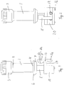
Figure 1 is a side view of a device according to the invention by means of which it is possible to simultaneously with the attachment of a bracket for a roofing sheet also achieve folding in of at least a part of an end portion of the connecting tongue of a bracket into the low flange, -
Figure 2 is a further side view of the device inFigure 1 , -
Figure 3 is another side view of the device inFigure 1 , and -
Figure 4 is a view from below of the device inFigures 1-3 . - As shown in
Figures 1-3 a device for simultaneously fastening and folding into a low flange of at least a part of an end portion of the connecting tongue of a bracket (not shown) at roofing sheet comprises a hollowelongated housing 1, afirst end 2 of which, in a preferred embodiment, is provided with asocket 3 for detachable connection to a driving apparatus (not shown), preferably in a form of an electric screw driver or a nailer. It is obvious that, in another embodiment, the driving apparatus can be fixedly attached to thehousing 1. - At a second end 4 of the housing an
elongated hollow means 5 is arranged, which is axially displaceably arranged in thehousing 1. Themeans 5 can be made in the form of ashaft 5, which projects outside the second end 4 of the housing. At the end of the hollow means projecting out of the housing is arranged afolding device 10, which includes apivotable folding arm 11. - The bracket for roofing sheet, which preferably are used together with the device according to the invention, will not be described in more detail below, since it is described in the above-mentioned Swedish patent document.
- In a preferred embodiment the driving apparatus is a driving apparatus provided with a rotatable driving shaft, which can be adapted to be connected to either a long bits (not shown) or an extension shaft (not shown), which extends through the
housing 1, the hollow means 5 and into a throughhole 15 in the folding device 10 (Figure 4 ). In the case of the extension shaft it can either be provided with a suitable screwing means adapted for the screw which is pre-mounted in the bracket or a bits holder, in which a suitable bits for the pre-mounted screw is mounted. It should be noted that the holes in thehollow housing 1, the hollow means 5 and thefolding device 10 are in line with each other. - When attaching the bracket to an underlay a folding in of at least a part of the end portion of the connecting tongue is carried out simultaneously. This is accomplished by an axial displacement between the
housing 1 and thefolding device 10 against each other, when the folding device is pressed against an underlay (not shown), such as an under-roofing, a first end 11a of thefolding arm 11 is given a radial movement by means of an actuation means 6 arranged at the second end 4 of the housing, so that said first end folds in at least a part of the end portion of the connecting tongue of a bracket mounted in the folding device into the low flange. - In the case of the driving apparatus being a driving apparatus having a rotatable driving shaft the axial displacement between the housing and the
folding device 10 will cause the screwing means/bits to engage the screw which is pre-mounted in the bracket, and as the screw is screwed into the underlay the actuation means 6 will progressively effect the folding arm for corresponding progressive folding of at least a part of the end portion of the connecting tongue into the low flange. - The bracket is adapted to be detachably attached to the
folding device 10 by clamping the connecting tongue of the bracket between asurface 20 of thefolding device 10 and a first end 11a of the folding arm, and/or the bracket is secured to the folding device using at least one magnet 12 (Figure 2 ). - Moreover, as can be seen from
Figure 1 , thefolding device 10 is provided with anarm 17 projecting perpendicular to the axial direction of thehollow means 5 to form a substantially L-shaped body as seen in cross section. The foldingarm 11 is pivotably mounted to the end of thearm 17 by apin 13, about at its centre. - From
Figures 1-3 it can be seen that the second end 4 of thehousing 1 is provided with an actuation means 6 having afirst surface 7, preferably an essentially conically shapedsurface 7, directed towards thefolding device 10. At an axial displacement between thehousing 1 and thefolding device 10 towards each other the conicallyshaped surface 7 is adapted to come into contact with a second end 11b of thefolding arm 11 so as to achieve the radial movement of the first end 11a of the folding arm towards the folding device. The second end 11b of thefolding arm 11 has a second surface 11c, and more particularly a rounded surface 11c as seen in the axial direction, said surface being adapted to cooperate with the conicallyshaped surface 7 of the actuation means 6, when thehousing 1 is pressed against thefolding device 10 so as to achieve a radial motion of the first end 11a of thefolding arm 11 and thereby folding of at least a part of the end portion of the connecting tongue of the bracket into the low flange. The foldingarm 11 is biased by means of a spring (not shown) towards its starting position, which is shown inFigure 1 , and the hollow means is biased towards its ejected position from the housing. Thehousing 1 and the hollow means 5 can thus perform a telescope motion relative to each other. - It is obvious for the man skilled in the art that the radial motion of the first end 11a of the
folding arm 11 can be made by a different method than the one that has been specified above, such as that the above-mentioned interactingfirst surface 7 and second surface 11c are replaced by interacting toothed surfaces or a surface of the actuation means, for instance, which cooperates with a roller, a wheel or corresponding means of the folding arm. It is also possible to adapt instead the substantially conically shaped surface in the form of the second surface 11c instead of thefirst surface 7, or to arrange conically shaped surfaces at both the first and the second surfaces. - From
figure 3 it can be seen that the axial displacement of the hollow means 5 in thehousing 1 is limited by preferably a stop means 18, preferably ascrew 18, which is adapted to run in a groove formed in thehousing 1, between the axial end surfaces of the groove. - To prevent the bracket from turning when the bracket is attached to the underlay, the surface of the
folding device 10 directed towards the underlay is provided with at least one, preferably two,guide pins 16 adapted to cooperate with corresponding guide holes in the bracket.
Claims (12)
- Device for simultaneous attachment of a bracket for roofing sheet to an underlay and folding into a low flange of plate or sheet coverage of at least a part of an end portion of a connecting tongue of said bracket, wherein the device comprises a hollow longitudinal housing (1), at a first end (2) of which is arranged a fixed or detachably mounted driving apparatus and at a second end (4) of which is arranged an elongated hollow means (5), which is axially displaceable in the housing (1) and which projects beyond the second end (4) of the housing, the projecting end of the hollow means being provided with a folding device (10) comprising a pivotable folding arm (11) having a first end (11a), the device further comprising an actuation means (6) arranged at the second end (4) of the housing (1) for giving, when the folding device (10) is pressed against the underlay thereby axially displacing the housing (1) and the folding device (10) against each other, a radial motion to said first end (11a) of said folding arm (11), so that said first end (11a) of the folding arm (11) folds into the low flange said at least a part of an end portion of the connecting tongue of the bracket, mounted in the folding device, while the bracket is being attached to the underlay.
- Device according to claim 1, wherein the actuation means (6) is provided with a first surface (7) directed towards the folding device (10), whereby, at axial displacement between the housing (1) and the folding device (10) against each other, the first surface (7) is adapted to contact and to cooperate with a second surface (11c) of a second end (11b) of the folding arm (11) so as to achieve the radial motion of the first end (11a) of the folding arm towards the bracket mounted in the folding device.
- Device according to claim 2, wherein the first surface (7) of the actuation means (6) has a substantially conically shaped surface (7), and the second surface (11c) of the second end (11b) of the folding arm (11) has a round surface (11c) as seen in the axial direction.
- Device according to any one of claims 1-3, wherein the folding device (10) is provided with an arm (17) which protrudes at right angle to the axial direction of the hollow means (5) to form a substantially L- shaped body, as seen in cross section, and the folding arm (11) is pivotably mounted at about its centre at the end of the arm (17).
- Device according to any one of claims 1-4, wherein the folding arm (11) is biased towards its starting position, and the hollow means (5) is biased towards its position protruding out of the housing (1).
- Device according to any one of claims 1-5, wherein the first end (2) of the housing (1) is provided with a socket (3) for detachably mounting of the driving apparatus.
- Device according to any one of claims 1-6, wherein the driving apparatus is a driving apparatus provided with a rotatable drive shaft, at which drive shaft either a bits or an extension shaft having a bits socket, extending through the housing (1), the hollow means (5) and into a through hole (15) arranged in the folding device (10), is mounted for screwing in a screw pre-mounted in the bracket.
- Device according to any one of claims 1-6, wherein the driving apparatus is a nailer.
- Device according to any one of claims 1-8, wherein the surface of the folding device (10) directed towards the underlay is provided with at least one, preferably two, guide pins (16) for cooperation with corresponding guide holes in the bracket.
- Device according to anyone of claims 1-9, wherein the bracket is adapted to be detachably fixed to the folding device (10) by clamping the connecting tongue of the bracket between a surface (20) of the folding device (10) and the first end (11a) of the folding arm (11).
- Device according to any one of claims 1-10, wherein the folding device (10) is provided with magnets (12) for detachable attachment of the bracket to the folding device.
- A method of attaching a bracket for roofing sheet, the method comprising attaching said bracket to an underlay using a driving apparatus being fixed or detachably mounted arranged at a first end (2) of a hollow longitudinal housing (1), and being characterized in using a device according to any one of claims 1-11, thereby simultaneously with attaching said bracket to the underlay, folding at least a part of an end portion of a connecting tongue of said bracket into a low flange of plate or sheet coverage by axially displacing the housing (1), at which the driving apparatus is arranged, towards a folding device (10) provided at an elongated hollow means (5) being arranged at a second end (4) of the housing (1), the housing (1) thereby actuating upon a folding arm (11) of the folding device (10) by means of an actuation means (6), such that a first end (11a) of said folding arm (11) folds said at least a part of an end portion of the connecting tongue of said bracket into the low flange of plate or sheet coverage.
Applications Claiming Priority (2)
| Application Number | Priority Date | Filing Date | Title |
|---|---|---|---|
| SE1050259A SE534675C2 (en) | 2010-03-19 | 2010-03-19 | Device for simultaneous fixing and folding of brackets for sheet metal roofs |
| PCT/SE2011/050293 WO2011115565A1 (en) | 2010-03-19 | 2011-03-17 | Device for simultaneous attachment and folding of brackets for roofing sheet |
Publications (3)
| Publication Number | Publication Date |
|---|---|
| EP2547838A1 EP2547838A1 (en) | 2013-01-23 |
| EP2547838A4 EP2547838A4 (en) | 2016-12-07 |
| EP2547838B1 true EP2547838B1 (en) | 2018-01-10 |
Family
ID=44649464
Family Applications (1)
| Application Number | Title | Priority Date | Filing Date |
|---|---|---|---|
| EP11756636.4A Active EP2547838B1 (en) | 2010-03-19 | 2011-03-17 | Device for simultaneous attachment and folding of brackets for roofing sheet |
Country Status (7)
| Country | Link |
|---|---|
| US (1) | US20130047406A1 (en) |
| EP (1) | EP2547838B1 (en) |
| AU (1) | AU2011227770B2 (en) |
| CA (1) | CA2793471A1 (en) |
| NZ (1) | NZ602051A (en) |
| SE (1) | SE534675C2 (en) |
| WO (1) | WO2011115565A1 (en) |
Family Cites Families (19)
| Publication number | Priority date | Publication date | Assignee | Title |
|---|---|---|---|---|
| US2944503A (en) * | 1954-05-12 | 1960-07-12 | Acme Steel Co | Crimping tool for forming roof deck |
| US2969754A (en) * | 1954-05-12 | 1961-01-31 | Acme Steel Co | Roof structure |
| JPS51135138A (en) * | 1975-05-19 | 1976-11-24 | Yoshinori Hiraoka | Splicing and fastening apparatus for continuous corrugated roofing |
| US4064819A (en) * | 1977-03-03 | 1977-12-27 | Atlanta Metal Products, Inc. | Machine for progressively closing flanges of cap strips on standing T-rib roofs |
| US4470186A (en) * | 1981-05-11 | 1984-09-11 | Knudson Gary Art | Reversible seaming apparatus with laterally separable rollers having parallel axes |
| SE9003740L (en) * | 1990-11-23 | 1992-05-24 | Bjarne Svanberg | MACHINE CONTAINS FIXING OF STRAPS ON ROOF PLATE |
| DE4201015A1 (en) * | 1991-01-16 | 1992-07-23 | Itw Ateco Gmbh | Stand to facilitate powered driving of self-drilling screws - has hand feed lever to increase thrust and uses operator's weight as hold-down force |
| US5243748A (en) * | 1992-06-30 | 1993-09-14 | M.I.C. Industries, Inc. | Crimper apparatus and method |
| US7574839B1 (en) * | 1995-06-07 | 2009-08-18 | Harold Simpson, Inc. | Roof assembly having increased resistance to sidelap shear |
| US5661886A (en) * | 1995-06-15 | 1997-09-02 | Smith; Jimmy M. | Combination clip installation and crimping tool |
| US5878617A (en) * | 1997-10-30 | 1999-03-09 | Parker; James R. | Pneumatic decking crimper |
| US5921454A (en) * | 1998-05-05 | 1999-07-13 | Illinois Tool Works Inc. | Roofing washer-dispensing and fastener-driving machine |
| CA2270060A1 (en) * | 1999-04-27 | 2000-10-27 | Michel Vachon | Crimping tool |
| JP2000352166A (en) * | 1999-06-09 | 2000-12-19 | Toho Sheet & Frame Co Ltd | Work method for coupled roof by tightening tool for fastener |
| EP1420908B1 (en) * | 2001-08-31 | 2006-06-07 | EDAG Engineering + Design Aktiengesellschaft | Roller folding head and method for folding a flange |
| US6760962B2 (en) * | 2002-05-14 | 2004-07-13 | Jason Proffitt | Hydraulic deck crimper |
| US7021108B2 (en) * | 2002-11-18 | 2006-04-04 | Varco Pruden Technologies, Inc. | Punching tool for connecting decking panels together |
| SE528746C2 (en) * | 2005-06-22 | 2007-02-06 | Bjarnes System Ab | Method and apparatus for making seam welded roof coatings of stainless steel |
| US7353584B2 (en) * | 2005-10-18 | 2008-04-08 | Consolidated Systems, Inc. | Deck tool |
-
2010
- 2010-03-19 SE SE1050259A patent/SE534675C2/en unknown
-
2011
- 2011-03-17 NZ NZ602051A patent/NZ602051A/en not_active IP Right Cessation
- 2011-03-17 US US13/634,715 patent/US20130047406A1/en not_active Abandoned
- 2011-03-17 AU AU2011227770A patent/AU2011227770B2/en not_active Ceased
- 2011-03-17 CA CA2793471A patent/CA2793471A1/en not_active Abandoned
- 2011-03-17 EP EP11756636.4A patent/EP2547838B1/en active Active
- 2011-03-17 WO PCT/SE2011/050293 patent/WO2011115565A1/en not_active Ceased
Non-Patent Citations (1)
| Title |
|---|
| None * |
Also Published As
| Publication number | Publication date |
|---|---|
| AU2011227770A1 (en) | 2012-09-20 |
| AU2011227770B2 (en) | 2015-05-07 |
| EP2547838A1 (en) | 2013-01-23 |
| SE534675C2 (en) | 2011-11-15 |
| CA2793471A1 (en) | 2011-09-22 |
| EP2547838A4 (en) | 2016-12-07 |
| US20130047406A1 (en) | 2013-02-28 |
| WO2011115565A1 (en) | 2011-09-22 |
| NZ602051A (en) | 2014-04-30 |
| SE1050259A1 (en) | 2011-09-20 |
Similar Documents
| Publication | Publication Date | Title |
|---|---|---|
| CN201325040Y (en) | Driving tool | |
| CN102917923B (en) | Windscreen wiper device | |
| US7980441B2 (en) | Setting tool | |
| CN104364112B (en) | The control device of tension | |
| WO2010042786A3 (en) | Powered surgical cutting and stapling apparatus with manually retractable firing system | |
| EP1943962A3 (en) | Improved curved end effector for a surgical stapling device | |
| WO2009067184A3 (en) | Bi-directional trimmer head spool with curved trimmer line guide | |
| EP2594360A3 (en) | Tool accessory for a power tool | |
| AU2011227770B2 (en) | Device for simultaneous attachment and folding of brackets for roofing sheet | |
| KR101616699B1 (en) | Install system of support unit for stone plate corbel | |
| WO2006124121A3 (en) | Weatherproof lap siding system | |
| CN102947164A (en) | Electric power steering | |
| WO2012083948A1 (en) | Arrangement for removing icicles | |
| EP2786841A1 (en) | Screw driver for collated screws and screw feeding machanism of screw driver | |
| CN109114085B (en) | Nut fastening clamp and nut fastening clamp assembly | |
| CN105270340A (en) | Wiper device and wiper blade for wiper device | |
| JP2020007791A (en) | Unfastening machine for fastened member and socket | |
| JP5038668B2 (en) | Mounting hardware such as temporary scaffolding | |
| CN107378869B (en) | Holding device for the adjustable fastening of an add-on device to a hand-held tool and hand-held tool having such a holding device | |
| KR101573404B1 (en) | Apparatus for working an external surface of body of the ship in vessel | |
| US20120160070A1 (en) | Adjustable working area cutting machine | |
| PL2080208T3 (en) | Electric switch, particularly park position switch for a windshield wiper motor | |
| HU0201200D0 (en) | ||
| US20180142737A1 (en) | Steering clamp yoke | |
| CN202863298U (en) | Automobile interior accessory mounting device and automobile |
Legal Events
| Date | Code | Title | Description |
|---|---|---|---|
| PUAI | Public reference made under article 153(3) epc to a published international application that has entered the european phase |
Free format text: ORIGINAL CODE: 0009012 |
|
| 17P | Request for examination filed |
Effective date: 20120914 |
|
| AK | Designated contracting states |
Kind code of ref document: A1 Designated state(s): AL AT BE BG CH CY CZ DE DK EE ES FI FR GB GR HR HU IE IS IT LI LT LU LV MC MK MT NL NO PL PT RO RS SE SI SK SM TR |
|
| DAX | Request for extension of the european patent (deleted) | ||
| RA4 | Supplementary search report drawn up and despatched (corrected) |
Effective date: 20161107 |
|
| RIC1 | Information provided on ipc code assigned before grant |
Ipc: E04D 15/04 20060101AFI20161031BHEP Ipc: E04D 3/362 20060101ALI20161031BHEP |
|
| GRAP | Despatch of communication of intention to grant a patent |
Free format text: ORIGINAL CODE: EPIDOSNIGR1 |
|
| STAA | Information on the status of an ep patent application or granted ep patent |
Free format text: STATUS: GRANT OF PATENT IS INTENDED |
|
| INTG | Intention to grant announced |
Effective date: 20170906 |
|
| GRAS | Grant fee paid |
Free format text: ORIGINAL CODE: EPIDOSNIGR3 |
|
| GRAA | (expected) grant |
Free format text: ORIGINAL CODE: 0009210 |
|
| STAA | Information on the status of an ep patent application or granted ep patent |
Free format text: STATUS: THE PATENT HAS BEEN GRANTED |
|
| RAP1 | Party data changed (applicant data changed or rights of an application transferred) |
Owner name: LINDAB AB |
|
| AK | Designated contracting states |
Kind code of ref document: B1 Designated state(s): AL AT BE BG CH CY CZ DE DK EE ES FI FR GB GR HR HU IE IS IT LI LT LU LV MC MK MT NL NO PL PT RO RS SE SI SK SM TR |
|
| REG | Reference to a national code |
Ref country code: GB Ref legal event code: FG4D |
|
| REG | Reference to a national code |
Ref country code: CH Ref legal event code: EP Ref country code: AT Ref legal event code: REF Ref document number: 962588 Country of ref document: AT Kind code of ref document: T Effective date: 20180115 |
|
| REG | Reference to a national code |
Ref country code: IE Ref legal event code: FG4D |
|
| REG | Reference to a national code |
Ref country code: FR Ref legal event code: PLFP Year of fee payment: 8 |
|
| REG | Reference to a national code |
Ref country code: DE Ref legal event code: R096 Ref document number: 602011044945 Country of ref document: DE |
|
| RAP2 | Party data changed (patent owner data changed or rights of a patent transferred) |
Owner name: LINDAB PROFIL AB |
|
| REG | Reference to a national code |
Ref country code: CH Ref legal event code: NV Representative=s name: ROSENICH PAUL; KUENSCH JOACHIM PATENTBUERO PAU, LI |
|
| REG | Reference to a national code |
Ref country code: DE Ref legal event code: R081 Ref document number: 602011044945 Country of ref document: DE Owner name: LINDAB PROFIL AB, SE Free format text: FORMER OWNER: LINDAB AB, BASTAD, SE |
|
| REG | Reference to a national code |
Ref country code: BE Ref legal event code: PD Owner name: LINDAB PROFIL AB; SE Free format text: DETAILS ASSIGNMENT: CHANGE OF OWNER(S), CESSION; FORMER OWNER NAME: LINDAB AB Effective date: 20180228 |
|
| REG | Reference to a national code |
Ref country code: SE Ref legal event code: TRGR |
|
| REG | Reference to a national code |
Ref country code: NL Ref legal event code: MP Effective date: 20180110 |
|
| REG | Reference to a national code |
Ref country code: AT Ref legal event code: MK05 Ref document number: 962588 Country of ref document: AT Kind code of ref document: T Effective date: 20180110 |
|
| PG25 | Lapsed in a contracting state [announced via postgrant information from national office to epo] |
Ref country code: NL Free format text: LAPSE BECAUSE OF FAILURE TO SUBMIT A TRANSLATION OF THE DESCRIPTION OR TO PAY THE FEE WITHIN THE PRESCRIBED TIME-LIMIT Effective date: 20180110 |
|
| PG25 | Lapsed in a contracting state [announced via postgrant information from national office to epo] |
Ref country code: HR Free format text: LAPSE BECAUSE OF FAILURE TO SUBMIT A TRANSLATION OF THE DESCRIPTION OR TO PAY THE FEE WITHIN THE PRESCRIBED TIME-LIMIT Effective date: 20180110 Ref country code: CY Free format text: LAPSE BECAUSE OF FAILURE TO SUBMIT A TRANSLATION OF THE DESCRIPTION OR TO PAY THE FEE WITHIN THE PRESCRIBED TIME-LIMIT Effective date: 20180110 Ref country code: LT Free format text: LAPSE BECAUSE OF FAILURE TO SUBMIT A TRANSLATION OF THE DESCRIPTION OR TO PAY THE FEE WITHIN THE PRESCRIBED TIME-LIMIT Effective date: 20180110 Ref country code: FI Free format text: LAPSE BECAUSE OF FAILURE TO SUBMIT A TRANSLATION OF THE DESCRIPTION OR TO PAY THE FEE WITHIN THE PRESCRIBED TIME-LIMIT Effective date: 20180110 Ref country code: ES Free format text: LAPSE BECAUSE OF FAILURE TO SUBMIT A TRANSLATION OF THE DESCRIPTION OR TO PAY THE FEE WITHIN THE PRESCRIBED TIME-LIMIT Effective date: 20180110 Ref country code: NO Free format text: LAPSE BECAUSE OF FAILURE TO SUBMIT A TRANSLATION OF THE DESCRIPTION OR TO PAY THE FEE WITHIN THE PRESCRIBED TIME-LIMIT Effective date: 20180410 |
|
| PG25 | Lapsed in a contracting state [announced via postgrant information from national office to epo] |
Ref country code: AT Free format text: LAPSE BECAUSE OF FAILURE TO SUBMIT A TRANSLATION OF THE DESCRIPTION OR TO PAY THE FEE WITHIN THE PRESCRIBED TIME-LIMIT Effective date: 20180110 Ref country code: LV Free format text: LAPSE BECAUSE OF FAILURE TO SUBMIT A TRANSLATION OF THE DESCRIPTION OR TO PAY THE FEE WITHIN THE PRESCRIBED TIME-LIMIT Effective date: 20180110 Ref country code: RS Free format text: LAPSE BECAUSE OF FAILURE TO SUBMIT A TRANSLATION OF THE DESCRIPTION OR TO PAY THE FEE WITHIN THE PRESCRIBED TIME-LIMIT Effective date: 20180110 Ref country code: BG Free format text: LAPSE BECAUSE OF FAILURE TO SUBMIT A TRANSLATION OF THE DESCRIPTION OR TO PAY THE FEE WITHIN THE PRESCRIBED TIME-LIMIT Effective date: 20180410 Ref country code: IS Free format text: LAPSE BECAUSE OF FAILURE TO SUBMIT A TRANSLATION OF THE DESCRIPTION OR TO PAY THE FEE WITHIN THE PRESCRIBED TIME-LIMIT Effective date: 20180510 Ref country code: GR Free format text: LAPSE BECAUSE OF FAILURE TO SUBMIT A TRANSLATION OF THE DESCRIPTION OR TO PAY THE FEE WITHIN THE PRESCRIBED TIME-LIMIT Effective date: 20180411 Ref country code: PL Free format text: LAPSE BECAUSE OF FAILURE TO SUBMIT A TRANSLATION OF THE DESCRIPTION OR TO PAY THE FEE WITHIN THE PRESCRIBED TIME-LIMIT Effective date: 20180110 |
|
| REG | Reference to a national code |
Ref country code: DE Ref legal event code: R097 Ref document number: 602011044945 Country of ref document: DE |
|
| REG | Reference to a national code |
Ref country code: FR Ref legal event code: TP Owner name: LINDAB PROFIL AB, SE Effective date: 20180910 |
|
| PG25 | Lapsed in a contracting state [announced via postgrant information from national office to epo] |
Ref country code: AL Free format text: LAPSE BECAUSE OF FAILURE TO SUBMIT A TRANSLATION OF THE DESCRIPTION OR TO PAY THE FEE WITHIN THE PRESCRIBED TIME-LIMIT Effective date: 20180110 Ref country code: RO Free format text: LAPSE BECAUSE OF FAILURE TO SUBMIT A TRANSLATION OF THE DESCRIPTION OR TO PAY THE FEE WITHIN THE PRESCRIBED TIME-LIMIT Effective date: 20180110 Ref country code: EE Free format text: LAPSE BECAUSE OF FAILURE TO SUBMIT A TRANSLATION OF THE DESCRIPTION OR TO PAY THE FEE WITHIN THE PRESCRIBED TIME-LIMIT Effective date: 20180110 Ref country code: IT Free format text: LAPSE BECAUSE OF FAILURE TO SUBMIT A TRANSLATION OF THE DESCRIPTION OR TO PAY THE FEE WITHIN THE PRESCRIBED TIME-LIMIT Effective date: 20180110 |
|
| PLBE | No opposition filed within time limit |
Free format text: ORIGINAL CODE: 0009261 |
|
| STAA | Information on the status of an ep patent application or granted ep patent |
Free format text: STATUS: NO OPPOSITION FILED WITHIN TIME LIMIT |
|
| PG25 | Lapsed in a contracting state [announced via postgrant information from national office to epo] |
Ref country code: SK Free format text: LAPSE BECAUSE OF FAILURE TO SUBMIT A TRANSLATION OF THE DESCRIPTION OR TO PAY THE FEE WITHIN THE PRESCRIBED TIME-LIMIT Effective date: 20180110 Ref country code: SM Free format text: LAPSE BECAUSE OF FAILURE TO SUBMIT A TRANSLATION OF THE DESCRIPTION OR TO PAY THE FEE WITHIN THE PRESCRIBED TIME-LIMIT Effective date: 20180110 Ref country code: DK Free format text: LAPSE BECAUSE OF FAILURE TO SUBMIT A TRANSLATION OF THE DESCRIPTION OR TO PAY THE FEE WITHIN THE PRESCRIBED TIME-LIMIT Effective date: 20180110 Ref country code: MC Free format text: LAPSE BECAUSE OF FAILURE TO SUBMIT A TRANSLATION OF THE DESCRIPTION OR TO PAY THE FEE WITHIN THE PRESCRIBED TIME-LIMIT Effective date: 20180110 Ref country code: CZ Free format text: LAPSE BECAUSE OF FAILURE TO SUBMIT A TRANSLATION OF THE DESCRIPTION OR TO PAY THE FEE WITHIN THE PRESCRIBED TIME-LIMIT Effective date: 20180110 |
|
| 26N | No opposition filed |
Effective date: 20181011 |
|
| REG | Reference to a national code |
Ref country code: IE Ref legal event code: MM4A |
|
| PG25 | Lapsed in a contracting state [announced via postgrant information from national office to epo] |
Ref country code: LU Free format text: LAPSE BECAUSE OF NON-PAYMENT OF DUE FEES Effective date: 20180317 |
|
| PG25 | Lapsed in a contracting state [announced via postgrant information from national office to epo] |
Ref country code: IE Free format text: LAPSE BECAUSE OF NON-PAYMENT OF DUE FEES Effective date: 20180317 |
|
| PG25 | Lapsed in a contracting state [announced via postgrant information from national office to epo] |
Ref country code: SI Free format text: LAPSE BECAUSE OF FAILURE TO SUBMIT A TRANSLATION OF THE DESCRIPTION OR TO PAY THE FEE WITHIN THE PRESCRIBED TIME-LIMIT Effective date: 20180110 |
|
| PG25 | Lapsed in a contracting state [announced via postgrant information from national office to epo] |
Ref country code: MT Free format text: LAPSE BECAUSE OF NON-PAYMENT OF DUE FEES Effective date: 20180317 |
|
| PG25 | Lapsed in a contracting state [announced via postgrant information from national office to epo] |
Ref country code: TR Free format text: LAPSE BECAUSE OF FAILURE TO SUBMIT A TRANSLATION OF THE DESCRIPTION OR TO PAY THE FEE WITHIN THE PRESCRIBED TIME-LIMIT Effective date: 20180110 |
|
| PG25 | Lapsed in a contracting state [announced via postgrant information from national office to epo] |
Ref country code: HU Free format text: LAPSE BECAUSE OF FAILURE TO SUBMIT A TRANSLATION OF THE DESCRIPTION OR TO PAY THE FEE WITHIN THE PRESCRIBED TIME-LIMIT; INVALID AB INITIO Effective date: 20110317 Ref country code: PT Free format text: LAPSE BECAUSE OF FAILURE TO SUBMIT A TRANSLATION OF THE DESCRIPTION OR TO PAY THE FEE WITHIN THE PRESCRIBED TIME-LIMIT Effective date: 20180110 |
|
| PG25 | Lapsed in a contracting state [announced via postgrant information from national office to epo] |
Ref country code: MK Free format text: LAPSE BECAUSE OF NON-PAYMENT OF DUE FEES Effective date: 20180110 |
|
| REG | Reference to a national code |
Ref country code: CH Ref legal event code: PCAR Free format text: NEW ADDRESS: ROTENBODENSTRASSE 12, 9497 TRIESENBERG (LI) |
|
| REG | Reference to a national code |
Ref country code: DE Ref legal event code: R082 Ref document number: 602011044945 Country of ref document: DE Representative=s name: ZACCO LEGAL RECHTSANWALTSGESELLSCHAFT MBH, DE |
|
| P01 | Opt-out of the competence of the unified patent court (upc) registered |
Effective date: 20230530 |
|
| PGFP | Annual fee paid to national office [announced via postgrant information from national office to epo] |
Ref country code: CH Payment date: 20250401 Year of fee payment: 15 |
|
| REG | Reference to a national code |
Ref country code: DE Ref legal event code: R082 Ref document number: 602011044945 Country of ref document: DE |
|
| REG | Reference to a national code |
Ref country code: CH Ref legal event code: U11 Free format text: ST27 STATUS EVENT CODE: U-0-0-U10-U11 (AS PROVIDED BY THE NATIONAL OFFICE) Effective date: 20260401 |
|
| PGFP | Annual fee paid to national office [announced via postgrant information from national office to epo] |
Ref country code: SE Payment date: 20260120 Year of fee payment: 16 |
|
| PGFP | Annual fee paid to national office [announced via postgrant information from national office to epo] |
Ref country code: GB Payment date: 20260119 Year of fee payment: 16 |
|
| PGFP | Annual fee paid to national office [announced via postgrant information from national office to epo] |
Ref country code: DE Payment date: 20260216 Year of fee payment: 16 |
|
| PGFP | Annual fee paid to national office [announced via postgrant information from national office to epo] |
Ref country code: BE Payment date: 20260122 Year of fee payment: 16 |
|
| PGFP | Annual fee paid to national office [announced via postgrant information from national office to epo] |
Ref country code: FR Payment date: 20260120 Year of fee payment: 16 |