EP0487482A1 - A machine for securing clips to metal roofing sheets - Google Patents
A machine for securing clips to metal roofing sheets Download PDFInfo
- Publication number
- EP0487482A1 EP0487482A1 EP91850289A EP91850289A EP0487482A1 EP 0487482 A1 EP0487482 A1 EP 0487482A1 EP 91850289 A EP91850289 A EP 91850289A EP 91850289 A EP91850289 A EP 91850289A EP 0487482 A1 EP0487482 A1 EP 0487482A1
- Authority
- EP
- European Patent Office
- Prior art keywords
- clip
- head
- lip
- sheet
- clips
- Prior art date
- Legal status (The legal status is an assumption and is not a legal conclusion. Google has not performed a legal analysis and makes no representation as to the accuracy of the status listed.)
- Withdrawn
Links
- 239000002184 metal Substances 0.000 title claims abstract description 7
- 238000005452 bending Methods 0.000 claims description 7
- 238000003780 insertion Methods 0.000 claims description 3
- 230000037431 insertion Effects 0.000 claims description 2
- 238000004873 anchoring Methods 0.000 description 4
- 238000002788 crimping Methods 0.000 description 1
- 238000000034 method Methods 0.000 description 1
- 230000004048 modification Effects 0.000 description 1
- 238000012986 modification Methods 0.000 description 1
Images

Classifications
-
- E—FIXED CONSTRUCTIONS
- E04—BUILDING
- E04D—ROOF COVERINGS; SKY-LIGHTS; GUTTERS; ROOF-WORKING TOOLS
- E04D3/00—Roof covering by making use of flat or curved slabs or stiff sheets
- E04D3/36—Connecting; Fastening
- E04D3/361—Connecting; Fastening by specially-profiled marginal portions of the slabs or sheets
- E04D3/362—Connecting; Fastening by specially-profiled marginal portions of the slabs or sheets by locking the edge of one slab or sheet within the profiled marginal portion of the adjacent slab or sheet, e.g. using separate connecting elements
-
- E—FIXED CONSTRUCTIONS
- E04—BUILDING
- E04D—ROOF COVERINGS; SKY-LIGHTS; GUTTERS; ROOF-WORKING TOOLS
- E04D15/00—Apparatus or tools for roof working
- E04D15/04—Apparatus or tools for roof working for roof coverings comprising slabs, sheets or flexible material
-
- E—FIXED CONSTRUCTIONS
- E04—BUILDING
- E04D—ROOF COVERINGS; SKY-LIGHTS; GUTTERS; ROOF-WORKING TOOLS
- E04D3/00—Roof covering by making use of flat or curved slabs or stiff sheets
- E04D3/36—Connecting; Fastening
- E04D3/361—Connecting; Fastening by specially-profiled marginal portions of the slabs or sheets
- E04D2003/3615—Separate fastening elements fixed to the roof structure and consisting of parts permitting relative movement to each other, e.g. for thermal expansion
-
- E—FIXED CONSTRUCTIONS
- E04—BUILDING
- E04D—ROOF COVERINGS; SKY-LIGHTS; GUTTERS; ROOF-WORKING TOOLS
- E04D15/00—Apparatus or tools for roof working
- E04D15/04—Apparatus or tools for roof working for roof coverings comprising slabs, sheets or flexible material
- E04D2015/042—Fixing to the roof supporting structure
Definitions
- the present invention relates to a machine for securing clips along one long edge of metal roofing sheets, in accordance with the preamble of Claim 1.
- the roofing sheets present along this one long edge of the sheet an edge part or web which is bent upwards to an angle of about 90° and the free lip part of which is bent inwards over the main surface of the sheet at an angle of about 90°.
- the clips to be fitted onto the roofing sheet have a generally flat web which is provided on one side thereof, at its bottom end, a base flange which is angled at abut 90° to said web and which has at its top end a tongue which is bent down towards the other side of the web.
- roofing sheets have earlier been fitted by manually anchoring the sheets manually to an underlying support surface with the aid of clips, which are connected manually to said one long edge of the sheet at respective anchoring locations.
- roofing sheets are normally anchored in position with the aid of two types of clips, a slide clip and a fixed clip.
- fitting clips to roof sheets mechanically is that the permitted distance between mutually adjacent clips can be selected in accordance with current regulations and standards, thereby enabling the number of clips used to be kept to a minimum while keeping to the stipulated clip spacing.
- the clips are positioned at shorter distances therebetween than is necessary, for the sake of safety.
- the object of the present invention is to provide a machine for mechanically fitting clips along one long edge of metal roofing sheets, so that the sheets can be anchored to the roof structure quickly and in a relatively simple fashion.
- the machine includes means for moving the roofing sheets in their longitudinal directions, a clip securing head, a clip magazine, means for transferring clips singly from the magazine to the head, means for driving the head together with a clip carried thereby into engagement with the edge of the roofing sheet at predetermined positions therealong, such as to secure a clip to the sheet in respective positions, wherein the head includes gripping means which grip around the bent lip part of the clip and clamps the bent end-part of the roofing sheet flange, and a punch or die means which is carried by the head and which functions to bring the bent part of the clip fitted to the edge of the roofing sheet into abutment with the raised edge of said sheet.
- the clamping means may include a rammer means which is connected to the punch.
- the head is also provided with a counter-pressure means, or anvil means, for coaction with the rammer means.
- This counter-pressure means may have the form of a lever which is pivotally mounted on the head.
- the machine may also include an upper lever, which is also pivotally mounted on the head.
- a power ram is connected between the respective one ends of the two lever arms, such as to drive the rammer and the counter-pressure means towards one another when securing a clip.
- the pivotal movement of the lower lever on the head, which lever forms the counter-pressure means, is limited and the machine may include adjusting means for adjusting the extent of lever movement.
- the machine also includes means for driving the head in the transverse direction of the roofing sheet, so as to enable the counter-pressure means to be moved in beneath the rim part of the sheet and, in connection therewith, to hook the bent part of the clip firmly onto the rim of the roofing sheet.
- the head is preferably moved in said transverse direction to the selected positions along the long edge of the roofing sheet at which a clip is to be fitted.
- the machine is also preferably provided with a holder by means of which the base part of the clip can be held temporarily adjacent the punch.
- the holder preferably includes an arm which is spring biased towards a closed position and which defines a clip insertion slot together with the punch.
- the magazine may include a stack magazine, in which the clips are positioned with their respective webs generally horizontal and their bases facing upwards, the lowermost clips in the magazine being ejected therefrom, by means of a piston-cylinder device in a direction defined by the bending line of the base part.
- the bent end-part of the clip will then rest on the counter-pressure means with the base of the clip positioned in the punch slot.
- the piston-cylinder device is activated, the punch and the rammer are driven downwards and the counter-pressure device is pivoted upwards into abutment with the bent end-part of the clip.
- the clip is bent and the bent-part of the clip is clamped or squeezed securely to the lip or edge of the roofing sheet.
- the clamping means is opened by returning the piston-cylinder device to its starting position, whereafter the head can be moved laterally and the roofing sheet can be moved in its longitudinal direction and a further clip inserted in the clamping means, whereafter the described working cycle can be repeated.
- FIG. 1 Shown in Figure 1 is a conveyor 1 which carries a metal roofing sheet or panel 2.
- One long edge of the roofing sheet has an edge-part 21 which is bent up at an angle of about 90° to form a flange and the free lip-part 22 of the flange is bent in over the main surface 23 of the sheet 2, so as to be substantially parallel therewith.
- the conveyor 1 is provided with drive means 11, such as to convey the roofing sheet 2 in a direction perpendicular to the plane of the Figure.
- the machine includes a head 3 which is moved by drive means 31 in the direction of the arrow 3, parallel with the main surface 23 of the sheet 2, at right angles to the longitudinal axis of said sheet.
- an upper two-arm lever 41 Pivotally mounted on an upper bearing or journal 4 on the head 3 is an upper two-arm lever 41, whose one arm is activated by a vertically positioned pneumatic piston-cylinder device 5.
- the other arm 43 of the lever 41 is connected to a clip-bending punch 6 provided with a fixed clamping or crimping jaw 61.
- the punch 6 is guided for linear movement on the head 3, substantially in a vertical direction.
- a pivot journal 7 which carries a lower two-arm lever 71, whose one arm 72 is connected to the lower end of the piston-cylinder device 5.
- the other arm 73 of the lever 71 forms a counter-pressure means 75 for coaction with the clamping jaw 61.
- the lever 71 also has a substantially vertical arm 76, whose one side coacts with an adjustable stop screw 31 provided in the head 3, and whose other side 77 is able to coact with an abutment surface 28 on the head 3.
- the head 3 also carries a clamping arm 62 which is pivot-ally mounted on a journal bearing 63 and biased towards a closed position by means of springs 64.
- the arm 62 defines, together with the punch 6, a clamping slot 65 which receives the base flange of a clip to be fitted onto the edge flange 22 of the roofing sheet with the aid of the machine.
- the bearing 45 located between the arm 43 of the upper lever and the punch 66 may exhibit play in the longitudinal direction of the lever 41 so as to allow the arm 43 to pivot around the journal 4 in spite of the fact that the punch 6 is guided for linear movement of the guide 6.
- a slide clip 8 which comprises a generally flat web 81, the bottom end of which has on one side thereof a base flange 82 which is angled from the web at substantially 90° and which is provided with screw-receiving holes 83.
- the upper part of the web 81 has provided therein an opening 84 which facilitates bending of the upper web part.
- the upper part of the web 81 is also provided with a bent or folded hooked part 85 on the opposite side of said web to the base flange 82.
- Figure 2 illustrates the initial starting position of a working operation.
- the head 3 is moved to the right in Figure 1 by means of the drive means 31, whereby the bent or hooked part 85 of the clip 81 will grip around the lippart 22 of the roofing sheet 2, as shown in Figure 3.
- the piston-cylinder device 5 is then activated, whereby the lever 71 will swing to the right, causing the counter-pressure device 25 to move upwards towards the clip and the lip-part 22.
- the lever 41 is swung by the piston-cylinder device 5 so as to cove the punch 6 downwards in its linear guide means, thereby clamping the clip part 85 firmly on the lip-part 22 of the roofing sheet as a result of downward movement of the clamping jaw 61 of the punch 6 and its force-coaction with the counter-pressure device 75.
- the nose-part 66 of the punch bends the web part 81 of the clip around the edge of the roofing sheet formed by the flange 21 and the lip 22.
- the extent to which the base part 82 of the clip is held firm by the clamping arm 62 is controlled by the wedge surfaces 67, 68, so that the clamping arm 62 will release its hold on the base part 82 in conjunction with the bending operation.
- the base part 82 is provided with holes 83 and the clamping arm 62 of the illustrated embodiment is provided with a ball which is received on one of the holes 83.
- the punch 6 may be provided with a recess corresponding to said ball.
- FIG. 7 illustrates schematically a stack magazine 9 for clips 8.
- the magazine 9 includes a container part 91 which receives clips 8 with their respective webs 81 positioned essentially horizontally and the base parts 82 thereof facing upwards.
- the bottom of the container part 91 is terminated with a stop plate 92, such that the lowermost clip 8 can be moved in the direction 86 defined by the bending line between the clip web 81 and the clip base 82, the bottom lip or edge of the container part 91 being adapted to the contours of the clip and spaced above the stop plate 92 so as to permit only one clip 8 to be ejected from the magazine at any one time.
- the magazine 9 is positioned such that the base part 82 of the clip 8 will be aligned with the corresponding slot or gap 65 between the punch 6 and its clamping arm 62, and such that the hooked part 85 of the clip is aligned with the nearest space above the counter-pressure device 75, so that the clip 8 can be transferred from the magazine 9 to its intended position in the clamping device according to Figure 1, simply by being moved in the direction 86 by means, e.g., of a ram 100, the piston rod 101 of which moves in the direction 86 and acts on the exposed, lowermost clip 8 in the magazine, as shown schematically in Figure 6.
Landscapes
- Engineering & Computer Science (AREA)
- Architecture (AREA)
- Civil Engineering (AREA)
- Structural Engineering (AREA)
- Mechanical Engineering (AREA)
- Clamps And Clips (AREA)
- Sheet Holders (AREA)
Abstract
A machine for fitting clips to metal roofing sheets comprises a clip securing head (3), a clip magazine (9), a ram means (100) for transferring clips (8) from the magazine (9) to the clamping means provided on the head (3), means (65) for temporarily holding a clip in the clamping means. The machine also includes means (31) for driving the head (3) in a manner to hook the clip onto the lip (22) of the roofing sheet and for returning the head from the clip hooking position, and means for advancing roofing sheets in their longitudinal direction, so that the clips can be fitted in selected positions along the long edge of the roofing sheet.
Description
- The present invention relates to a machine for securing clips along one long edge of metal roofing sheets, in accordance with the preamble of Claim 1.
- The roofing sheets present along this one long edge of the sheet an edge part or web which is bent upwards to an angle of about 90° and the free lip part of which is bent inwards over the main surface of the sheet at an angle of about 90°. The clips to be fitted onto the roofing sheet have a generally flat web which is provided on one side thereof, at its bottom end, a base flange which is angled at abut 90° to said web and which has at its top end a tongue which is bent down towards the other side of the web.
- Such roofing sheets have earlier been fitted by manually anchoring the sheets manually to an underlying support surface with the aid of clips, which are connected manually to said one long edge of the sheet at respective anchoring locations. Roofing sheets are normally anchored in position with the aid of two types of clips, a slide clip and a fixed clip.
- In recent times, mechanical means have been proposed for mounting clips along one long edge of metal roofing sheets or panels. The clips are preferably mounted on the sheet mechanically in a local workshop, thereby facilitating the work of anchoring the roofing sheet to the underlying support surface with the aid of the clips. This proposal is based on the realization that one and the same type of slide clip can be counted at regular intervals along the edge of the sheet concerned. When the side clip can be modified to provide a fixed clip, this modification can be effected at the time of anchoring the clip concerned to the roof structure. Alternatively, all of the clips applied mechanically to the roofing sheet may be slide clips, in which case supplementary fixed clips are mounted at those positions where fixed connection of the roofing sheet to the underlying support surface is required. Only a small number of fixed clips are required for fitting roofing sheets to a roof structure.
- One advantage with fitting clips to roof sheets mechanically is that the permitted distance between mutually adjacent clips can be selected in accordance with current regulations and standards, thereby enabling the number of clips used to be kept to a minimum while keeping to the stipulated clip spacing. According to the older technique of fitting clips to roof sheeting with the aid of mechanical means, the clips are positioned at shorter distances therebetween than is necessary, for the sake of safety.
- The object of the present invention is to provide a machine for mechanically fitting clips along one long edge of metal roofing sheets, so that the sheets can be anchored to the roof structure quickly and in a relatively simple fashion.
- This object is achieved with the inventive machine defined in the following Claim 1.
- Further embodiments of the machine are defined in the depending Claims.
- The machine includes means for moving the roofing sheets in their longitudinal directions, a clip securing head, a clip magazine, means for transferring clips singly from the magazine to the head, means for driving the head together with a clip carried thereby into engagement with the edge of the roofing sheet at predetermined positions therealong, such as to secure a clip to the sheet in respective positions, wherein the head includes gripping means which grip around the bent lip part of the clip and clamps the bent end-part of the roofing sheet flange, and a punch or die means which is carried by the head and which functions to bring the bent part of the clip fitted to the edge of the roofing sheet into abutment with the raised edge of said sheet. The clamping means may include a rammer means which is connected to the punch. The head is also provided with a counter-pressure means, or anvil means, for coaction with the rammer means. This counter-pressure means may have the form of a lever which is pivotally mounted on the head. The machine may also include an upper lever, which is also pivotally mounted on the head. A power ram is connected between the respective one ends of the two lever arms, such as to drive the rammer and the counter-pressure means towards one another when securing a clip. The pivotal movement of the lower lever on the head, which lever forms the counter-pressure means, is limited and the machine may include adjusting means for adjusting the extent of lever movement. The machine also includes means for driving the head in the transverse direction of the roofing sheet, so as to enable the counter-pressure means to be moved in beneath the rim part of the sheet and, in connection therewith, to hook the bent part of the clip firmly onto the rim of the roofing sheet. The head is preferably moved in said transverse direction to the selected positions along the long edge of the roofing sheet at which a clip is to be fitted. The machine is also preferably provided with a holder by means of which the base part of the clip can be held temporarily adjacent the punch. The holder preferably includes an arm which is spring biased towards a closed position and which defines a clip insertion slot together with the punch. The magazine may include a stack magazine, in which the clips are positioned with their respective webs generally horizontal and their bases facing upwards, the lowermost clips in the magazine being ejected therefrom, by means of a piston-cylinder device in a direction defined by the bending line of the base part. The bent end-part of the clip will then rest on the counter-pressure means with the base of the clip positioned in the punch slot. When the piston-cylinder device is activated, the punch and the rammer are driven downwards and the counter-pressure device is pivoted upwards into abutment with the bent end-part of the clip. As the punch and the rammer continue to move downwards, the clip is bent and the bent-part of the clip is clamped or squeezed securely to the lip or edge of the roofing sheet. The clamping means is opened by returning the piston-cylinder device to its starting position, whereafter the head can be moved laterally and the roofing sheet can be moved in its longitudinal direction and a further clip inserted in the clamping means, whereafter the described working cycle can be repeated.
- The invention will now be described in more detail with reference to an exemplifying embodiment thereof and also with reference to the schematic drawings, in which
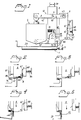
- Figure 1 is a schematic side view of an inventive machine;
- Figures 2, 3, 4 and 5 illustrate different working operations of the machine illustrated in Figure 1;
- Figure 6 is a schematic end view of the machine with associated magazine and a feed punch for transferring clips from the magazine to the clamping means;
- Figure 7 illustrates schematically a clip magazine belonging to the illustrated machine; and
- Figure 8 illustrates a clip handled by said machine.
- Shown in Figure 1 is a conveyor 1 which carries a metal roofing sheet or
panel 2. One long edge of the roofing sheet has an edge-part 21 which is bent up at an angle of about 90° to form a flange and the free lip-part 22 of the flange is bent in over themain surface 23 of thesheet 2, so as to be substantially parallel therewith. The conveyor 1 is provided with drive means 11, such as to convey theroofing sheet 2 in a direction perpendicular to the plane of the Figure. The machine includes ahead 3 which is moved by drive means 31 in the direction of thearrow 3, parallel with themain surface 23 of thesheet 2, at right angles to the longitudinal axis of said sheet. Pivotally mounted on an upper bearing orjournal 4 on thehead 3 is an upper two-arm lever 41, whose one arm is activated by a vertically positioned pneumatic piston-cylinder device 5. Theother arm 43 of thelever 41 is connected to a clip-bending punch 6 provided with a fixed clamping or crimpingjaw 61. Thepunch 6 is guided for linear movement on thehead 3, substantially in a vertical direction. - Mounted on the lower part of the
head 3 is a pivot journal 7 which carries a lower two-arm lever 71, whose onearm 72 is connected to the lower end of the piston-cylinder device 5. Theother arm 73 of thelever 71 forms a counter-pressure means 75 for coaction with theclamping jaw 61. Thelever 71 also has a substantiallyvertical arm 76, whose one side coacts with anadjustable stop screw 31 provided in thehead 3, and whoseother side 77 is able to coact with an abutment surface 28 on thehead 3. - The
head 3 also carries aclamping arm 62 which is pivot-ally mounted on a journal bearing 63 and biased towards a closed position by means ofsprings 64. Thearm 62 defines, together with thepunch 6, aclamping slot 65 which receives the base flange of a clip to be fitted onto theedge flange 22 of the roofing sheet with the aid of the machine. Thebearing 45 located between thearm 43 of the upper lever and thepunch 66 may exhibit play in the longitudinal direction of thelever 41 so as to allow thearm 43 to pivot around thejournal 4 in spite of the fact that thepunch 6 is guided for linear movement of theguide 6. - Shown in Figure 8 is a
slide clip 8 which comprises a generallyflat web 81, the bottom end of which has on one side thereof abase flange 82 which is angled from the web at substantially 90° and which is provided with screw-receivingholes 83. The upper part of theweb 81 has provided therein anopening 84 which facilitates bending of the upper web part. The upper part of theweb 81 is also provided with a bent or folded hookedpart 85 on the opposite side of said web to thebase flange 82. - It is assumed that the
head 3 illustrated in Figure 1 is moved to the left in said Figure to the position shown in Figure 2. With the head in this position, aclip 8 is introduced into the marine such that thehooked part 85 of the clip will face downwards and rest on the counter-pressure means 75, while thebase flange 82 of the clip is located in theslot 65 and temporarily held firmly therein. A clip magazine and means for transferring a clip from the magazine to the machine will be described in detail herebelow with reference to Figures 6 and 7. - Reference is made first, however, to Figure 2, which illustrates the initial starting position of a working operation. Starting from the operational state shown in Figure 2, the
head 3 is moved to the right in Figure 1 by means of the drive means 31, whereby the bent or hookedpart 85 of theclip 81 will grip around thelippart 22 of theroofing sheet 2, as shown in Figure 3. The piston-cylinder device 5 is then activated, whereby thelever 71 will swing to the right, causing the counter-pressure device 25 to move upwards towards the clip and the lip-part 22. At the same time, thelever 41 is swung by the piston-cylinder device 5 so as to cove thepunch 6 downwards in its linear guide means, thereby clamping theclip part 85 firmly on the lip-part 22 of the roofing sheet as a result of downward movement of theclamping jaw 61 of thepunch 6 and its force-coaction with thecounter-pressure device 75. The nose-part 66 of the punch bends theweb part 81 of the clip around the edge of the roofing sheet formed by theflange 21 and thelip 22. The extent to which thebase part 82 of the clip is held firm by theclamping arm 62 is controlled by thewedge surfaces clamping arm 62 will release its hold on thebase part 82 in conjunction with the bending operation. As shown in Figure 8, thebase part 82 is provided withholes 83 and theclamping arm 62 of the illustrated embodiment is provided with a ball which is received on one of theholes 83. Thepunch 6 may be provided with a recess corresponding to said ball. - When the piston-
cylinder device 5 is returned to its starting position, thepunch 6 is lifted and thelower lever 71 is swung back to its starting position, wherein thecounter-pressure device 75 moves downwards away from the crimp joint established between theclip 8 and thelip 22. The punch drive means 31 can now be activated to move thehead 3 to the left in Figure 1, to the configuration shown in Figure 2, wherewith a further clip can be introduced into the machine and the afore-described working cycle repeated. - Figure 7 illustrates schematically a
stack magazine 9 forclips 8. Themagazine 9 includes acontainer part 91 which receivesclips 8 with theirrespective webs 81 positioned essentially horizontally and thebase parts 82 thereof facing upwards. The bottom of thecontainer part 91 is terminated with astop plate 92, such that thelowermost clip 8 can be moved in thedirection 86 defined by the bending line between theclip web 81 and theclip base 82, the bottom lip or edge of thecontainer part 91 being adapted to the contours of the clip and spaced above thestop plate 92 so as to permit only oneclip 8 to be ejected from the magazine at any one time. - The
magazine 9 is positioned such that thebase part 82 of theclip 8 will be aligned with the corresponding slot orgap 65 between thepunch 6 and itsclamping arm 62, and such that thehooked part 85 of the clip is aligned with the nearest space above thecounter-pressure device 75, so that theclip 8 can be transferred from themagazine 9 to its intended position in the clamping device according to Figure 1, simply by being moved in thedirection 86 by means, e.g., of aram 100, thepiston rod 101 of which moves in thedirection 86 and acts on the exposed,lowermost clip 8 in the magazine, as shown schematically in Figure 6.
Claims (7)
- A machine for fitting clips 8 along one long edge of metal roofing sheets, said sheets having an upwardly bent flange (1) along said one edge with the free lip-part (22) of said flange (1) being folded in over the main surface (23) of the sheet substantially parallel with said surface, and wherein said clips (8) have a generally flat web (81) which presents on one side of the bottom end thereof a base flange (82) which is angled at substantially 90° to said web and which at its upper end present a hooked lip (85) which bends down towards the other side of said web (81), characterized by
means (11) for advancing the roofing sheets in the direction of their longitudinal axes;
a clip fitting head (3);
a magazine (9) for clips (8);
means (100) for transferring clips (8) singly from the magazine (9) to the head (3);
means (31) for driving the head (3) horizontally towards and away from the lip (22) of a roofing sheet at predetermined positions along the said long edge of said sheet, said head including
holder means (75, 65) for temporarily holding a clip with the edge-insertion gap of the hooked lip (85) of said clip in alignment with the free end of the sheet lip (22) and with the clip web (82) facing away from the main surface (23) of said roofing sheet;
clamping means (4, 5, 6, 7) carried by the head (3) and functioning to clamp the hooked lip (85) of the clip (8) onto the lip-part (82) of the roofing sheet and to bend the clip web (80) around that edge which is defined by the flange (21) of the roofing sheet and the lip-part (22) into abutment with the flange (21) of the roofing sheet. - A machine according to Claim 1, characterized in that the clamping means includes a counter-pressure device (75) which is intended for insertion beneath the lip-part (22) of said roofing sheet, and a punch (6) provided with a clamping shoulder (61) and a bending nose (66), wherein the clamping shoulder (61) coacts with the counter-pressure device (75) such as to clamp the clip firmly to the roofing sheet, and wherein said bending nose (66) functions to bend the clip upon movement of the punch towards the counter-pressure device (75).
- A machine according to Claim 1 or 2, characterized in that the counter-pressure device (75) functions to form a support for the hooked part (85) of the clip.
- A machine according to any one of Claim 1-3, characterized in that the clamping means includes a piston-cylinder device (5) which functions to move the punch (6) backwards and forwards through the intermediary of a lever (41) pivotally mounted (4) on the head (3).
- A machine according to any one of Claims 1-4, characterized in that the counter-pressure device (75) is formed on one arm (73) of the lever (71) which is journalled (7) for limited pivotal movement on the head (3), and the other arm (72) of which lever (71) carries the piston-cylinder device (5).
- A machine according to any one of Claims 1-5, characterized in that the head (3) carries adjuster means (31) which coacts with the lever (71) in a manner to define the end position of the counter-pressure device (75) during a clamping operation.
- A machine according to any one of Claims 1-6, characterized in that the clip magazine (9) is a stack magazine; and in that the clip transfer means includes a linear driving ram (100) which functions to transfer the bottom clip (8) in the magazine (9) linearly to the clip-receiving means provided on the clip head (3).
Applications Claiming Priority (2)
| Application Number | Priority Date | Filing Date | Title |
|---|---|---|---|
| SE9003740A SE9003740L (en) | 1990-11-23 | 1990-11-23 | MACHINE CONTAINS FIXING OF STRAPS ON ROOF PLATE |
| SE9003740 | 1990-11-23 |
Publications (1)
| Publication Number | Publication Date |
|---|---|
| EP0487482A1 true EP0487482A1 (en) | 1992-05-27 |
Family
ID=20380995
Family Applications (1)
| Application Number | Title | Priority Date | Filing Date |
|---|---|---|---|
| EP91850289A Withdrawn EP0487482A1 (en) | 1990-11-23 | 1991-11-21 | A machine for securing clips to metal roofing sheets |
Country Status (2)
| Country | Link |
|---|---|
| EP (1) | EP0487482A1 (en) |
| SE (1) | SE9003740L (en) |
Cited By (5)
| Publication number | Priority date | Publication date | Assignee | Title |
|---|---|---|---|---|
| FR2740159A1 (en) * | 1995-10-20 | 1997-04-25 | Maury Nz | Fixing mechanism for covers with standing seams |
| EP0927797A1 (en) * | 1997-12-31 | 1999-07-07 | Rudolf Dipl.-Ing. Treiber | Apparatus for applying clips for metal roofs |
| WO2013066229A1 (en) * | 2011-10-31 | 2013-05-10 | Bjarnes System Ab | Mounting clip holder |
| EP2773822A4 (en) * | 2011-10-31 | 2015-05-27 | Bjarnes System Ab | MOUNTING CLIPS FOR ROOF |
| EP2547838A4 (en) * | 2010-03-19 | 2016-12-07 | Bjarnes System Ab | DEVICE FOR THE SIMULTANEOUS FASTENING AND FOLDING OF ROOF ROOF SUPPORTS |
Citations (5)
| Publication number | Priority date | Publication date | Assignee | Title |
|---|---|---|---|---|
| DE617386C (en) * | 1933-06-22 | 1935-08-17 | Hermann Boesch | Double seaming pliers designed with ª�-shaped interlocking jaws |
| US2408557A (en) * | 1945-01-19 | 1946-10-01 | Glen H Huntington | Sheet metal roofing |
| FR1321524A (en) * | 1962-02-07 | 1963-03-22 | Labbee Ets | Mounting bracket tool for standing seam cover sheets |
| FR2318985A1 (en) * | 1975-07-23 | 1977-02-18 | Kjolsrud Birger | Insulating panel with sheet screw and washer fixture - with setting frame and tubes to lead screws into position |
| US4372022A (en) * | 1980-04-24 | 1983-02-08 | The Ceco Corporation | Machine for progressively closing flanges of cap strips on standing rib roofs |
-
1990
- 1990-11-23 SE SE9003740A patent/SE9003740L/en not_active Application Discontinuation
-
1991
- 1991-11-21 EP EP91850289A patent/EP0487482A1/en not_active Withdrawn
Patent Citations (5)
| Publication number | Priority date | Publication date | Assignee | Title |
|---|---|---|---|---|
| DE617386C (en) * | 1933-06-22 | 1935-08-17 | Hermann Boesch | Double seaming pliers designed with ª�-shaped interlocking jaws |
| US2408557A (en) * | 1945-01-19 | 1946-10-01 | Glen H Huntington | Sheet metal roofing |
| FR1321524A (en) * | 1962-02-07 | 1963-03-22 | Labbee Ets | Mounting bracket tool for standing seam cover sheets |
| FR2318985A1 (en) * | 1975-07-23 | 1977-02-18 | Kjolsrud Birger | Insulating panel with sheet screw and washer fixture - with setting frame and tubes to lead screws into position |
| US4372022A (en) * | 1980-04-24 | 1983-02-08 | The Ceco Corporation | Machine for progressively closing flanges of cap strips on standing rib roofs |
Cited By (5)
| Publication number | Priority date | Publication date | Assignee | Title |
|---|---|---|---|---|
| FR2740159A1 (en) * | 1995-10-20 | 1997-04-25 | Maury Nz | Fixing mechanism for covers with standing seams |
| EP0927797A1 (en) * | 1997-12-31 | 1999-07-07 | Rudolf Dipl.-Ing. Treiber | Apparatus for applying clips for metal roofs |
| EP2547838A4 (en) * | 2010-03-19 | 2016-12-07 | Bjarnes System Ab | DEVICE FOR THE SIMULTANEOUS FASTENING AND FOLDING OF ROOF ROOF SUPPORTS |
| WO2013066229A1 (en) * | 2011-10-31 | 2013-05-10 | Bjarnes System Ab | Mounting clip holder |
| EP2773822A4 (en) * | 2011-10-31 | 2015-05-27 | Bjarnes System Ab | MOUNTING CLIPS FOR ROOF |
Also Published As
| Publication number | Publication date |
|---|---|
| SE9003740L (en) | 1992-05-24 |
| SE9003740D0 (en) | 1990-11-23 |
Similar Documents
| Publication | Publication Date | Title |
|---|---|---|
| US5054678A (en) | Furniture clip/tool | |
| US5020202A (en) | Tool to clip together sheet metal ends | |
| CN113618358A (en) | Shell turnover mechanism assembled by stainless steel hasp, pull ring assembling device and system | |
| CN118926898B (en) | Full-automatic haircut scissors torsional spring accessory assembly device | |
| CA1233702A (en) | Slip lock forming apparatus | |
| US4870749A (en) | Jaw and feeder assembly for advancing hinge to a work station | |
| AU2014240278A1 (en) | Apparatus and method for inserting angle plates and closing duct seams | |
| NO783274L (en) | APPLIANCE FOR PLACING CABLES IN ELECTRICAL CLAMPS | |
| US6263557B1 (en) | Apparatus and method for inserting angle plates in channel shaped flanges of a duct | |
| CN113118764B (en) | Motor capacitor assembly device | |
| CN215934041U (en) | Terminal machine pencil loading attachment | |
| CA1181442A (en) | Clamping apparatus | |
| CN114310980A (en) | Mechanical clamping jaw and automatic arc-shaped steel plate taking and placing system applying same | |
| GB2230074A (en) | Apparatus for affixing fasteners to a conveyor belt | |
| CN112938511B (en) | Clamp and stacking robot with same | |
| EP0920931B1 (en) | Apparatus for bending a metal sheet | |
| CN210914298U (en) | Automatic material receiving system | |
| CN220074564U (en) | Automatic pre-assembly equipment for flywheel parts | |
| CN216816791U (en) | Automatic resistance detection device | |
| CN113113827A (en) | Pin inserting equipment | |
| EP0679455B1 (en) | Auxiliary machining device, particularly partial bending and shearing in a programmmable sheet bending brake | |
| US12257618B1 (en) | Apparatus and method for closing duct seams and for inserting angle plates and closing duct seams | |
| US4790062A (en) | Apparatus for stripping an electrical conductor | |
| CN216681014U (en) | Tail hole direction selecting device of hinge hydraulic oil cylinder | |
| CN220127531U (en) | Feeding device |
Legal Events
| Date | Code | Title | Description |
|---|---|---|---|
| PUAI | Public reference made under article 153(3) epc to a published international application that has entered the european phase |
Free format text: ORIGINAL CODE: 0009012 |
|
| AK | Designated contracting states |
Kind code of ref document: A1 Designated state(s): AT BE CH DE DK FR LI SE |
|
| STAA | Information on the status of an ep patent application or granted ep patent |
Free format text: STATUS: THE APPLICATION IS DEEMED TO BE WITHDRAWN |
|
| 18D | Application deemed to be withdrawn |
Effective date: 19920528 |