EP2546529A2 - System zu Einblasen eines Fluids, Verdichter sowie Turbomaschine - Google Patents
System zu Einblasen eines Fluids, Verdichter sowie Turbomaschine Download PDFInfo
- Publication number
- EP2546529A2 EP2546529A2 EP12005134A EP12005134A EP2546529A2 EP 2546529 A2 EP2546529 A2 EP 2546529A2 EP 12005134 A EP12005134 A EP 12005134A EP 12005134 A EP12005134 A EP 12005134A EP 2546529 A2 EP2546529 A2 EP 2546529A2
- Authority
- EP
- European Patent Office
- Prior art keywords
- nozzles
- nozzle
- flow
- compressor
- turbomachine
- Prior art date
- Legal status (The legal status is an assumption and is not a legal conclusion. Google has not performed a legal analysis and makes no representation as to the accuracy of the status listed.)
- Withdrawn
Links
- 239000012530 fluid Substances 0.000 title claims description 21
- 238000011144 upstream manufacturing Methods 0.000 claims abstract description 6
- 238000002347 injection Methods 0.000 claims description 13
- 239000007924 injection Substances 0.000 claims description 13
- 238000007664 blowing Methods 0.000 description 4
- 238000000926 separation method Methods 0.000 description 3
- 238000005086 pumping Methods 0.000 description 2
- 230000002411 adverse Effects 0.000 description 1
- 238000001514 detection method Methods 0.000 description 1
- 230000000694 effects Effects 0.000 description 1
- 230000002093 peripheral effect Effects 0.000 description 1
Images

Classifications
-
- F—MECHANICAL ENGINEERING; LIGHTING; HEATING; WEAPONS; BLASTING
- F02—COMBUSTION ENGINES; HOT-GAS OR COMBUSTION-PRODUCT ENGINE PLANTS
- F02C—GAS-TURBINE PLANTS; AIR INTAKES FOR JET-PROPULSION PLANTS; CONTROLLING FUEL SUPPLY IN AIR-BREATHING JET-PROPULSION PLANTS
- F02C7/00—Features, components parts, details or accessories, not provided for in, or of interest apart form groups F02C1/00 - F02C6/00; Air intakes for jet-propulsion plants
- F02C7/22—Fuel supply systems
-
- F—MECHANICAL ENGINEERING; LIGHTING; HEATING; WEAPONS; BLASTING
- F04—POSITIVE - DISPLACEMENT MACHINES FOR LIQUIDS; PUMPS FOR LIQUIDS OR ELASTIC FLUIDS
- F04D—NON-POSITIVE-DISPLACEMENT PUMPS
- F04D27/00—Control, e.g. regulation, of pumps, pumping installations or pumping systems specially adapted for elastic fluids
- F04D27/02—Surge control
- F04D27/0207—Surge control by bleeding, bypassing or recycling fluids
- F04D27/0238—Details or means for fluid reinjection
-
- F—MECHANICAL ENGINEERING; LIGHTING; HEATING; WEAPONS; BLASTING
- F04—POSITIVE - DISPLACEMENT MACHINES FOR LIQUIDS; PUMPS FOR LIQUIDS OR ELASTIC FLUIDS
- F04D—NON-POSITIVE-DISPLACEMENT PUMPS
- F04D29/00—Details, component parts, or accessories
- F04D29/40—Casings; Connections of working fluid
- F04D29/52—Casings; Connections of working fluid for axial pumps
- F04D29/522—Casings; Connections of working fluid for axial pumps especially adapted for elastic fluid pumps
- F04D29/526—Details of the casing section radially opposing blade tips
-
- F—MECHANICAL ENGINEERING; LIGHTING; HEATING; WEAPONS; BLASTING
- F04—POSITIVE - DISPLACEMENT MACHINES FOR LIQUIDS; PUMPS FOR LIQUIDS OR ELASTIC FLUIDS
- F04D—NON-POSITIVE-DISPLACEMENT PUMPS
- F04D29/00—Details, component parts, or accessories
- F04D29/66—Combating cavitation, whirls, noise, vibration or the like; Balancing
- F04D29/661—Combating cavitation, whirls, noise, vibration or the like; Balancing especially adapted for elastic fluid pumps
- F04D29/667—Combating cavitation, whirls, noise, vibration or the like; Balancing especially adapted for elastic fluid pumps by influencing the flow pattern, e.g. suppression of turbulence
-
- F—MECHANICAL ENGINEERING; LIGHTING; HEATING; WEAPONS; BLASTING
- F04—POSITIVE - DISPLACEMENT MACHINES FOR LIQUIDS; PUMPS FOR LIQUIDS OR ELASTIC FLUIDS
- F04D—NON-POSITIVE-DISPLACEMENT PUMPS
- F04D29/00—Details, component parts, or accessories
- F04D29/66—Combating cavitation, whirls, noise, vibration or the like; Balancing
- F04D29/68—Combating cavitation, whirls, noise, vibration or the like; Balancing by influencing boundary layers
- F04D29/681—Combating cavitation, whirls, noise, vibration or the like; Balancing by influencing boundary layers especially adapted for elastic fluid pumps
- F04D29/684—Combating cavitation, whirls, noise, vibration or the like; Balancing by influencing boundary layers especially adapted for elastic fluid pumps by fluid injection
-
- F—MECHANICAL ENGINEERING; LIGHTING; HEATING; WEAPONS; BLASTING
- F05—INDEXING SCHEMES RELATING TO ENGINES OR PUMPS IN VARIOUS SUBCLASSES OF CLASSES F01-F04
- F05D—INDEXING SCHEME FOR ASPECTS RELATING TO NON-POSITIVE-DISPLACEMENT MACHINES OR ENGINES, GAS-TURBINES OR JET-PROPULSION PLANTS
- F05D2270/00—Control
- F05D2270/01—Purpose of the control system
- F05D2270/10—Purpose of the control system to cope with, or avoid, compressor flow instabilities
- F05D2270/101—Compressor surge or stall
- F05D2270/102—Compressor surge or stall caused by working fluid flow velocity profile distortion
Definitions
- the invention relates to a system for injecting a fluid into a wall boundary layer of a flow in a turbomachine.
- compressors in turbomachinery can regularly operate when operating the compressor outside a design point of the blades a so-called compressor pumps, in which the pressure in the compressor as a result of flow separation on the blades from rear to front degrades and a return flow is formed.
- a compressor pumping adversely affects the efficiency of the turbomachine.
- high loads occur in the blading, which are in part due to swinging or fluttering during the backflow phase.
- the risk of flow separation can be reduced if a wall boundary layer of the annular space flow is energized.
- the energization of the wall boundary layer can take place on the one hand by passive systems such as stator-side ribs or depressions.
- active systems which provide a blowing of a fluid through a plurality of circumferentially arranged nozzles in the annulus flow.
- Known active systems have nozzles with a round cross-section, which, however, only a very limited energizing of the wall boundary layer takes place and also high mixing losses occur.
- such high nozzle cross-sections cause a relatively strong reaction of the annular space flow on the nozzle flow.
- the object of the invention is to provide a system for blowing a fluid into a wall boundary layer of a flow in a turbomachine, which eliminates the aforementioned disadvantages and allows better energization and a reduction of mixing losses. Furthermore, it is an object of the invention to provide a compressor with a higher surge limit and a turbomachine with improved efficiency.
- a system for injecting a fluid into a wall boundary layer of a flow in a turbomachine has a plurality of nozzles arranged in a flow-restricting sidewall and oriented obliquely in the flow direction.
- the nozzles each have a rectangular flat nozzle cross-section.
- the rectangular flat and in particular slit-like nozzle cross-section of the so-called Coanda effect is improved and utilized more efficiently, creating an improved Energetistechnik the wall boundary layer occurs with minimal mixing losses.
- Efficiency can be further increased if, in each case, an injection channel with a bottleneck forming an interface is arranged upstream of the nozzles.
- the constriction allows the nozzle to have a low annulus pressure, thus placing a surge of pressure away from the sidewall into the nozzle.
- the fluid to be injected occurs perpendicular to the interface, whereby it is coupled without refraction in the nozzle.
- the interface defines the nozzle cross-section and the fluid in the nozzles or nozzle flow is not subject to additional pressure or velocity detection.
- constriction can be made aerodynamic, if the injection channel tapers in the direction of the constriction wedge or funnel-shaped
- the nozzles are made flat in the flow direction, since the fluid is thereby blown almost in the axial direction of the flow.
- the nozzles are set at an angle ⁇ 40 ° in the flow direction. Preferably, they are employed at an angle of 30 ° in the flow direction.
- nozzle exit surfaces are oriented tangentially to the direction of rotation. whereby the nozzle flow is swirl-free blown into the flow.
- the nozzle exit surfaces can be turned to the direction of rotation. They can be employed both in the direction of rotation and against the direction of rotation. For example, they are oriented at an angle of 20 ° in or against the direction of rotation.
- a compressor according to the invention has a system according to the invention for injecting a fluid into a wall boundary layer.
- Such a compressor is characterized by a significantly expanded pumping limit and thus by a high compressor stability and a reduced blade load.
- the compressor stability can be effectively increased even with a minimum amount of fluid when the system is positioned with its nozzles opposite the blade areas where flow separation is expected.
- the nozzles are therefore arranged on the stator side in the region of trailing edges of at least one blade row formed by rotor blades.
- a turbomachine according to the invention has a compressor according to the invention.
- Such a turbomachine is characterized by low efficiency losses and thus by a high efficiency, since the energization of the wall boundary layer improved and mixing losses are reduced.
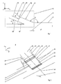
- FIG. 1 shows a partial section through an annular space 1 of a compressor of an aircraft engine.
- the annular space 1, in which the low annular space pressure p1 prevails, is radially bounded by a side wall 2 and flows through a flow 4 oriented in the longitudinal direction x of the aircraft engine.
- a dashed framed system 6 with a plurality of nozzles 8 and with a plurality of injection channels 10 is arranged on the circumference.
- the system 6 is used to energize a wall boundary layer of the flow 4 and allows injection of a fluid 12 with a high injection pressure p 2 into the annular space 1.
- the nozzles 8 are evenly spaced from each other distributed over the circumference of the annular space 1. They are each located downstream of a blow-in channel 10 and open into the annulus 1. As in FIG. 2 shown, they have a nozzle longitudinal axis xd, which is employed obliquely to the longitudinal axis x of the aircraft engine and thus to the flow 4.
- the nozzles 8 each have two lateral walls 14, 16 as well as a radially inner or inner wall 18 and a radially outer or outer wall 20.
- the walls 14, 16, 18, 20 define a rectangular flat and constant nozzle cross section shown in longitudinal cross-section 22.
- the blowing channels 10 are arranged between the nozzles 8 and a blower, not shown. As in FIG. 2 they each have two lateral walls 24, 26 and a radially inner wall 28 and a radially outer wall 30.
- the walls 24, 26, 28, 30 define a tapered in the flow direction rectangular cross-section.
- the lateral walls 24, 26 and the inner wall 28 are oriented parallel to the nozzle longitudinal axis xd and go flush in the lateral Düsenwauditch 14, 16 and in the inner nozzle wall 18 via.
- the outer wall 30 of the injection channels 10 is oriented obliquely in the direction of the nozzle longitudinal axis xd, whereby a cross-sectional taper formed in FIG. 1 figured bottleneck 32 is created, which defines an orthogonal to the nozzle longitudinal axis xd employed interface 34.
- the boundary surface 34 separates the high injection pressure p 2 from the low annulus pressure p 1, based on the pressure conditions.
- the high injection pressure p 2 prevails upstream of the interface 34 in the injection channels 10.
- the low annulus pressure p1 prevails downstream of the interface 34 in the nozzles 8 and in the annulus 1.
- the interface 34 forms a parting plane between two differently dense media 4, 12 or fluids, wherein, however, the fluid 12 is coupled into the thinner medium 4 without refraction due to the orientation of the interface 34 orthogonal to the nozzle longitudinal axis xd.
- the nozzle longitudinal axis xd is made flat to the longitudinal axis x of the aircraft engine.
- "Flat” means in an outer angle ⁇ between the side wall 2 and the outer nozzle wall 20 with ⁇ ⁇ 150 °.
- the annulus 1, as in FIG. 1 shown may be radially expanded downstream of the nozzle 8, so that a partial flow of the fluid 12 and a nozzle flow is injected axially or quasi axially into the wall boundary layer.
- the nozzle 8 each have a in FIG. 2 cross-hatched nozzle exit surface 36. This opens, as in the FIGS. 3, 4 and 5 shown, in each case radially opposite a trailing edge region 38 of a blade row formed by blades 40 in the annular space. 1
- the nozzle exit surfaces 36 run tangentially in the circumferential direction y and thus tangentially to the direction of rotation.
- the nozzle exit surfaces 36 are employed for swirling the fluid 12 through an angle ⁇ in the direction of rotation.
- the nozzle exit surfaces 36 are employed for swirling the fluid 12 through an angle ⁇ against the direction of rotation.
- a system for injecting a fluid into a wall boundary layer of a flow in a turbomachine having a plurality of nozzles disposed in a flow restricting sidewall and oriented obliquely in the flow direction, the nozzles each having a rectangular flat nozzle cross section, a compressor with such a system and a turbomachine with such a compressor.
Landscapes
- Engineering & Computer Science (AREA)
- Mechanical Engineering (AREA)
- General Engineering & Computer Science (AREA)
- Chemical & Material Sciences (AREA)
- Combustion & Propulsion (AREA)
- Life Sciences & Earth Sciences (AREA)
- Sustainable Development (AREA)
- Structures Of Non-Positive Displacement Pumps (AREA)
Abstract
Description
- Die Erfindung betrifft ein System zum Einblasen eines Fluids in eine Wandgrenzschicht einer Strömung in einer Turbomaschine nach dem Oberbegriff des Patentanspruchs 1, einen Verdichter sowie eine Turbomaschine.
- Bei Verdichtern in Turbomaschinen kann regelmäßig beim Betreiben der Verdichter außerhalb eines Auslegungspunktes der Laufschaufeln ein sogenanntes Verdichterpumpen einsetzen, bei dem sich der Druck im Verdichter in Folge einer Strömungsablösung an den Laufschaufeln von hinten nach vorne abbaut und eine Rückströmung gebildet wird. Ein derartiges Verdichterpumpen wirkt sich nachteilig auf den Wirkungsgrad der Turbomaschine aus. Zudem treten in der Beschaufelung hohe Belastungen auf, die zum Teil auf ein Schwingen bzw. Flattern während der Rückströmphase zurückzufähren sind. Die Gefahr einer Strömungsablösung lässt sich reduzieren, wenn eine Wandgrenzschicht der Ringraumströmung energetisiert wird. Die Energetisierung der Wandgrenzschicht kann zum einen durch passive Systeme wie statorseitige Rippen oder Vertiefungen erfolgen. Zum anderen sind aktive Systeme bekannt, die ein Einblasen eines Fluids durch eine Vielzahl von umfangsseitig angeordneten Düsen in die Ringraumströmung vorsehen. Bekannte aktive Systeme haben Düsen mit einem runden Querschnitt, wodurch jedoch nur eine stark begrenzte Energetisierung der Wandgrenzschicht erfolgt und zudem hohe Vermischungsverluste auftreten. Aus der
DE 10 2008 052 372 A1 ist ein aktives System mit rechteckigen Düsenquerschnitten und einem Längen-Höhen-Verhältnis von etwa l/h = 3 bekannt. Derartig hohe Düsenquerschnitte bewirken jedoch eine verhältnismäßig starke Rückwirkung der Ringraumströmung auf die Düsenströmung. - Aufgabe der Erfindung ist es, ein System zum Einblasen eines Fluids in eine Wandgrenzschicht einer Strömung in eine Turbomaschine zu schaffen, das die vorgenannten Nachteile beseitigt und eine bessere Energetisierung sowie eine Reduzierung von Vermischungsverlusten ermöglicht. Des Weiteren ist es Aufgabe der Erfindung, einen Verdichter mit einer höheren Pumpgrenze sowie eine Turbomaschine mit einem verbesserten Wirkungsgrad zu schaffen.
- Diese Aufgabe wird gelöst durch ein System mit den Merkmalen des Patentanspruchs 1, durch einen Verdichter mit den Merkmalen des Patentanspruchs 10 sowie durch eine Turbomaschine mit den Merkmalen des Patentanspruchs 12.
- Ein erfindungsgemäßes System zum Einblasen eines Fluids in eine Wandgrenzschicht einer Strömung in einer Turbomaschine hat eine Vielzahl von Düsen, die in einer die Strömung begrenzenden Seitenwandung angeordnet und schräg in Strömungsrichtung orientiert sind. Erfindungsgemäß haben die Düsen jeweils einen rechteckigen flachen Düsenquerschnitt. Insbesondere haben die Düsen einen Düsenquerschnitt mit einem Längen-Höhen-Verhältnis (l/h) von etwa l/h = 4 bis 20. Durch den rechteckigen flachen und insbesondere schlitzartigen Düsenquerschnitt wird der sogenannte Coanda-Effekt verbessert und effizienter ausgenutzt, wodurch eine verbesserte Energetisierung der Wandgrenzschicht bei minimalen Vermischungsverlusten erfolgt.
- Die Effizienz lässt sich weiter steigern, wenn stromaufwärts der Düsen jeweils ein Einblaskanal mit einer eine Grenzfläche bildenden Engstelle angeordnet ist. Die Engstelle ermöglicht, dass in der Düse ein niedriger Ringraumdruck herrscht und somit ein Druckstoß weg von der Seitenwandung in die Düse gelegt wird. Hierdurch tritt das einzublasende Fluid senkrecht auf die Grenzfläche auf, wodurch es ohne Brechung in die Düse eingekoppelt wird.
- Um Strömungsturbulenzen stromabwärts der Engstelle innerhalb den Düsen zu reduzieren, ist es vorteilhaft, wenn die Grenzfläche den Düsenquerschnitt definiert und das Fluid in den Düsen bzw. die Düsenströmung keiner zusätzlichen Druck- oder Geschwindigkeitsverfinderung unterliegt.
- Die Engstelle lässt sich strömungsgünstig gestalten, wenn der Einblaskanal in Richtung der Engstelle keil- bzw. trichterförmig verjüngt ist
- Zur weiteren Effizienzsteigerung kann es vorteilhaft sein, wenn die Düsen in Strömungsrichtung flach angestellt sind, da das Fluid hierdurch nahezu in Axialrichtung der Strömung eingeblasen wird.
- Beispielsweise sind die Düsen in einem Winkel ≤40° in Strömungsrichtung angestellt. Bevorzugterweise sind sie in einem Winkel von 30° in Strömungsrichtung angestellt.
- Bei einem Ausführungsbeispiel sind Düsenaustrittsflächen tangential zur Rotationsrichtung orientiert. wodurch die Düsenströmung drallbefreit in die Strömung eingeblasen wird.
- Zur Drallbeaufschlagung des eingeblasenen Fluids können die Düsenaustrittsflächen zur Rotationsrichtung angestellt sein. Dabei können sie sowohl in Rotationsrichtung als auch gegen die Rotationsrichtung angestellt sein. Beispielsweise sind sie um einen Winkel von 20° in bzw. gegen die Rotationsrichtung orientiert.
- Ein erfindungsgemäßer Verdichter hat ein erfindungsgemäßes System zum Einblasen eines Fluids in eine Wandgrenzschicht. Ein derartiger Verdichter zeichnet sich durch eine deutlich erweiterte Pumpgrenze und somit durch eine hohe Verdichterstabilität und eine reduzierte Schaufelbelastung aus. Zudem erfolgt nahezu bzw. keine Rückwirkung der Ringraumströmung des Verdichters auf die Düsenströmung des Systems, so dass das System in jedem Betriebszustand des Verdichters stabil betrieben werden kann.
- Die Verdichterstabilität lässt sich bereits mit einer minimalen Fluidmenge wirkungsvoll erhöhen, wenn das System mit seinen Düsen gegentiber den Schaufelbereichen positioniert ist, in denen eine Strömungsablösung zu erwarten ist. Bei einem Ausführungsbeispiel sind die Düsen daher statorseitig im Bereich von Hinterkanten zumindest einer von Laufschaufeln gebildeten Laufschaufelreihe angeordnet.
- Eine erfindungsgemäße Turbomaschine hat einen erfindungsgemäßen Verdichter. Eine derartige Turbomaschine zeichnet sich durch geringe Wirkungsgradverluste und somit durch einen hohen Wirkungsgrad aus, da die Energetisierung der Wandgrenzschicht verbessert und Vermischungsverluste reduziert sind.
- Sonstige vorteilhafte Ausführungsbeispiele der Erfindung sind Gegenstand weiterer Unterensprüche.
- Im Folgenden werden bevorzugte Ausführungsbeispiele der Erfindung anhand stark vereinfachter schematischer Darstellungen näher erläutert. Es zeigen:
-
Figur 1 einen Teilschnitt durch einen Ringraum eines Verdichters einer Turbomaschine, -
Figur 2 eine perspektivische Darstellung eines erfindungsgemäßen Systems, und -
Figuren 3, 4 und 5 Draufsichten auf einen abgewickelten Umfangsabschnitt einer Laufschaufelreihe mit jeweils einer statorseitigen Systemdüse. -
Figur 1 zeigt einen Teilschnitt durch einen Ringraum 1 eines Verdichters eines Flugzeugtriebwerks. Der Ringraum 1, in dem der niedrige Ringraumdruck p1 herrscht, wird von einer Seitenwandung 2 radial begrenzt und von einer in Längsrichtung x des Flugzeugtriebwerks orientierten Strömung 4 durchströmt. - In einem axialen Abschnitt der Seitenwandung 2 ist umfangsseitig ein gestrichelt umrahmtes System 6 mit einer Vielzahl von Düsen 8 und mit einer Vielzahl von Einblaskanälen 10 angeordnet. Das System 6 dient zur Energetisierung einer Wandgrenzschicht der Strömung 4 und ermöglicht ein Einblasen eines Fluids 12 mit einem hohen Einblasdruck p2 in den Ringraum 1.
- Die Düsen 8 sind gleichmäßig voneinander beabstandet über den Umfang des Ringraums 1 verteilt. Sie sind jeweils stromabwärts eines Einblaskanals 10 angeordnet und münden in den Ringraum 1. Wie in
Figur 2 gezeigt, haben sie eine Düsenlängsachse xd, die schräg zur Längsachse x des Flugzeugtriebwerks und somit zur Strömung 4 angestellt ist. - Die Düsen 8 haben jeweils zwei seitliche Wandungen 14, 16 sowie eine radial innen liegende bzw. innere Wandung 18 sowie eine radial außen liegende bzw. äußere Wandung 20. Die Wandungen 14, 16,18, 20 definieren einen längsschraffiert dargestellten rechteckigen flachen und konstanten Düsenquerschnitt 22. Der Düsenquerschnitt 22 ist über die Düsenlänge xd konstant und weist mit einem Längen-Höhen-Verhältnis (l/h) von etwa l/h = 4 bis 20 eine schlitzartige Form auf.
- Die Einblaskanäle 10 sind zwischen den Düsen 8 und einem nicht gezeigten Gebläse angeordnet. Wie in
Figur 2 gezeigt, haben sie jeweils zwei seitliche Wandungen 24, 26 sowie eine radial innere Wandung 28 und eine radial äußere Wandung 30. Die Wandungen 24, 26, 28, 30 definieren einen sich in Strömungsrichtung keilförmig verjüngenden rechteckigen Querschnitt. Dabei sind die seitlichen Wandungen 24, 26 sowie die innere Wandung 28 parallel zur Düsenlängsachse xd orientiert und gehen bündig in die seitlichen Düsenwaudungen 14, 16 bzw. in die innere Düsenwandung 18 über. Die äußere Wandung 30 der Einblaskanäle 10 ist schräg in Richtung der Düsenlängsachse xd orientiert, wodurch eine als Querschnittsverjüngung ausgebildete inFigur 1 bezifferte Engstelle 32 geschaffen wird, die eine orthogonal zur Düsenlängsachse xd angestellte Grenzfläche 34 definiert. - Die Grenzfläche 34 trennt bezogen auf die Druckverhältnisse den hohen Einblasdruck p2 von dem niedrigen Ringraumdruck p1. Der hohe Einblasdruck p2 herrscht stromaufwärts der Grenzfläche 34 in den Einblaskanälen 10 vor. Der niedrige Ringraumdruck p1 herrscht stromabwärts der Grenzfläche 34 in den Düsen 8 und in dem Ringraum 1 vor. Somit bildet die Grenzfläche 34 eine Trennebene zwischen zwei unterschiedlich dichten Medien 4,12 bzw. Fluiden aus, wobei jedoch das Fluid 12 aufgrund der Ausrichtung der Grenzfläche 34 orthogonal zur Düsenlängsachse xd ohne Brechung in das dünnere Medium 4 eingekoppelt wird.
- Zur Ermöglichung einer Einblasung des Fluids 12 nahezu in Axialrichtung der Strömung 4 ist die Düsenlängsachse xd flach zur Längsachse x des Flugzeugtriebwerks angestellt. "Flach" bedeutet dabei in einem Außenwinkel α zwischen der Seitenwandung 2 und der äußeren Düsenwandung 20 mit α ≥ 150°. Alternativ bedeutet "flach" in einem Innenwinkel β zwischen der Seitenwandung 2 und der inneren Düsenwandung 18 bzw. der inneren Einblaskanalwandung 28 mit β ≤ 40°, bevorzugterweise β = 30°. Ergänzend sei erwähnt, dass der Ringraum 1, wie in
Figur 1 gezeigt, stromabwärts der Düsen 8 radial erweitert sein kann, so dass ein Teilstrom des Fluid 12 bzw. einer Düsenströmung axial bzw. quasi axial in die Wandgrenzschicht eingeblasen wird. - Die Düsen- 8 haben jeweils eine in
Figur 2 kreuzschraffiert dargestellte Düsenaustrittsfläche 36. Diese mündet, wie in denFiguren 3, 4 und 5 gezeigt, jeweils radial gegenüber einem Hinterkantenbereich 38 einer von Laufschaufeln 40 gebildeten Schaufelreihe in den Ringraum 1. - Wie ebenfalls in
Figur 3 gezeigt, verlaufen die Düsenaustrittsflächen 36 bei einem Ausführungsbeispiel tangential in Umfangsrichtung y und somit tangential zur Rotationsrichtung. - Bei einem in
Figur 4 gezeigten Ausführungsbeispiel sind die Düsenaustrittsflächen 36 zur Drallbeaufschlagung des Fluids 12 um einen Winkel γ in Rotationsrichtung angestellt. - Bei einem in
Figur 5 gezeigten Ausführungsbeispiel sind die Düsenaustrittsflächen 36 zur Drallbeaufschlagung des Fluids 12 um einen Winkel γ gegen die Rotationsrichtung angestellt. Bevorzugterweise beträgt bei den Ausfuhrungsbeispielen nach denFiguren 4 und 5 der Winkel γ ± 20° in Rotationsrichtung bzw. Umfangsrichtung y. - Offenbart sind ein System zum Einblasen eines Fluids in eine Wandgrenzschicht einer Strömung in einer Turbomaschine mit einer Vielzahl von Düsen, die in einem einer der Strömung begrenzenden Seitenwandung angeordnet und schräg in Strömungsrichtung orientiert sind, wobei die Düsen jeweils einen rechteckigen flachen Düsenquerschnitt haben, ein Verdichter mit einem derartigen System sowie eine Turbomaschine mit einem derartigen Verdichter.
-
- 1
- Ringraum
- 2
- Seitenwandung
- 4
- Strömung
- 6
- System
- 8
- Düsen
- 10
- Einblaskanal
- 12
- Fluid
- 14
- seitliche Wandung
- 16
- seitliche Wandung
- 18
- innere Wandung
- 20
- äußere Wandung
- 22
- Düsenquerschnitt
- 24
- seitliche Wandung
- 26
- seitliche Wandung
- 28
- innere Wandung
- 30
- äußere Wandung
- 32
- Engstelle
- 34
- Grenzfläche
- 36
- Düsenaustrittsfläche
- 38
- Hinterkantenbereich
- 40
- Laufschaufel
- 1
- Länge Düsenquerschnitt
- h
- Höhe Düsenquerschnitt
- p1
- Ringaumdruck
- p2
- Einblasdruck
- x
- Längsache Flugzeugtriebwerk
- y
- Umfangsrichtung / Rotationsrichtung
- z
- Hochrichtung / Radialrichtung
- xd
- Düsenlängsachse
- α
- Außenwinkel
- β
- Innenwinkel
- γ
- Winkel Düsenaustrittsfläche zur Rotationsrichtung
Claims (12)
- System (6) zum Einblasen eines Fluids (12) in eine Wandgrenzschicht einer Strömung (4) in einer Turbomaschine, mit einer Vielzahl von Düsen (8), die in einer die Strömung (4) begrenzenden Seitenwandung (2), angeordnet und schräg in Strömungsrichtung (x) orientiert sind, dadurch gekennzeichnet, dass die Düsen (8) jeweils einen rechteckigen flachen Düsenquerschnitt (22) haben.
- System nach Anspruch 1, wobei stromaufwärts der Düsen (8) jeweils ein Einblaskanal (10) mit einer eine Grenzfläche (34) bildenden Engstelle (32) angeordnet ist.
- System nach Anspruch 2, wobei die Grenzfläche (34) den Düsenquerschnitt (22) definiert.
- System nach Anspruch 2 oder 3, wobei der Einblaskanal (10) stromaufwärts der Engstelle (32) trichterförmig erweitert ist.
- System nach einem der vorhergehenden Ansprüche, wobei die Düsen (8) in Strömungsrichtung flach angestellt sind.
- System nach Anspruch 4, wobei die Düsen (8) in einem Winkel (β) ≤ 40° in Strömungsrichtung angestellt sind.
- System nach einem der vorhergehenden Ansprüche, wobei Düsenaustrittsflächen (36) tangential zur Rotationsrichtung orientiert sind.
- System nach einem Ansprüche 1 bis 6, wobei die Düsenaustrittsflächen (36) in Rotationsrichtung angestellt sind.
- System nach einem Ansprüche 1 bis 6, wobei die Düsenaustrittsflächen (36) gegen die Rotationsrichtung angestellt sind.
- Verdichter mit einem System (6) nach einem der vorhergehenden Ansprüche.
- Verdichter nach Anspruch 10, wobei Düsen (8) des Systems (6) statorseitig im Hinterkantenbereich (38) zumindest einer von Laufschaufeln (40) gebildeten Schaufelreihe angeordnet sind.
- Turbomaschine mit einem Verdichter nach einem Anspruch 10 oder 11.
Applications Claiming Priority (1)
| Application Number | Priority Date | Filing Date | Title |
|---|---|---|---|
| DE102011107523.6A DE102011107523B4 (de) | 2011-07-15 | 2011-07-15 | System zum Einblasen eines Fluids, Verdichter sowie Turbomaschine |
Publications (2)
| Publication Number | Publication Date |
|---|---|
| EP2546529A2 true EP2546529A2 (de) | 2013-01-16 |
| EP2546529A3 EP2546529A3 (de) | 2018-04-04 |
Family
ID=46581693
Family Applications (1)
| Application Number | Title | Priority Date | Filing Date |
|---|---|---|---|
| EP12005134.7A Withdrawn EP2546529A3 (de) | 2011-07-15 | 2012-07-12 | System zu Einblasen eines Fluids, Verdichter sowie Turbomaschine |
Country Status (3)
| Country | Link |
|---|---|
| US (1) | US9074533B2 (de) |
| EP (1) | EP2546529A3 (de) |
| DE (1) | DE102011107523B4 (de) |
Families Citing this family (3)
| Publication number | Priority date | Publication date | Assignee | Title |
|---|---|---|---|---|
| US9567942B1 (en) * | 2010-12-02 | 2017-02-14 | Concepts Nrec, Llc | Centrifugal turbomachines having extended performance ranges |
| US12134984B1 (en) | 2023-11-17 | 2024-11-05 | Rtx Corporation | Fluidic compressor inlet guide vanes |
| US12215624B1 (en) | 2023-11-17 | 2025-02-04 | Rtx Corporation | Fluidic compressor inlet guide vane |
Citations (1)
| Publication number | Priority date | Publication date | Assignee | Title |
|---|---|---|---|---|
| DE102008052372A1 (de) | 2008-10-20 | 2010-04-22 | Mtu Aero Engines Gmbh | Verdichter |
Family Cites Families (15)
| Publication number | Priority date | Publication date | Assignee | Title |
|---|---|---|---|---|
| GB1518293A (en) * | 1975-09-25 | 1978-07-19 | Rolls Royce | Axial flow compressors particularly for gas turbine engines |
| KR100198721B1 (ko) * | 1991-01-30 | 1999-06-15 | 레비스 스테픈 이 | 개선된 케이스를 갖는 가스 터어빈 엔진 |
| RU2034175C1 (ru) * | 1993-03-11 | 1995-04-30 | Центральный институт авиационного моторостроения им.П.И.Баранова | Турбокомпрессор |
| US6574965B1 (en) * | 1998-12-23 | 2003-06-10 | United Technologies Corporation | Rotor tip bleed in gas turbine engines |
| US6585479B2 (en) * | 2001-08-14 | 2003-07-01 | United Technologies Corporation | Casing treatment for compressors |
| DE102004030597A1 (de) * | 2004-06-24 | 2006-01-26 | Rolls-Royce Deutschland Ltd & Co Kg | Strömungsarbeitsmaschine mit Aussenradstrahlerzeugung am Stator |
| DE102004055439A1 (de) * | 2004-11-17 | 2006-05-24 | Rolls-Royce Deutschland Ltd & Co Kg | Strömungsarbeitsmaschine mit dynamischer Strömungsbeeinflussung |
| DE102007037924A1 (de) * | 2007-08-10 | 2009-02-12 | Rolls-Royce Deutschland Ltd & Co Kg | Strömungsarbeitsmaschine mit Ringkanalwandausnehmung |
| DE102008014957A1 (de) * | 2008-03-19 | 2009-09-24 | Rolls-Royce Deutschland Ltd & Co Kg | Gasturbinenverdichter mit Zapfluftentnahme |
| DE102008015207A1 (de) * | 2008-03-20 | 2009-09-24 | Rolls-Royce Deutschland Ltd & Co Kg | Fluid-Injektor-Düse |
| DE102008016800A1 (de) * | 2008-04-02 | 2009-10-08 | Mtu Aero Engines Gmbh | Gasturbinenverdichter |
| DE102008017844A1 (de) * | 2008-04-08 | 2009-10-15 | Rolls-Royce Deutschland Ltd & Co Kg | Strömungsmaschine mit Fluid-Injektorbaugruppe |
| DE102008029605A1 (de) * | 2008-06-23 | 2009-12-24 | Rolls-Royce Deutschland Ltd & Co Kg | Schaufeldeckband mit Durchlass |
| DE102008037154A1 (de) * | 2008-08-08 | 2010-02-11 | Rolls-Royce Deutschland Ltd & Co Kg | Strömungsarbeitsmaschine |
| DE102008061184A1 (de) * | 2008-12-09 | 2010-06-10 | Mtu Aero Engines Gmbh | Verdichter |
-
2011
- 2011-07-15 DE DE102011107523.6A patent/DE102011107523B4/de not_active Expired - Fee Related
-
2012
- 2012-07-12 EP EP12005134.7A patent/EP2546529A3/de not_active Withdrawn
- 2012-07-13 US US13/549,074 patent/US9074533B2/en not_active Expired - Fee Related
Patent Citations (1)
| Publication number | Priority date | Publication date | Assignee | Title |
|---|---|---|---|---|
| DE102008052372A1 (de) | 2008-10-20 | 2010-04-22 | Mtu Aero Engines Gmbh | Verdichter |
Also Published As
| Publication number | Publication date |
|---|---|
| US9074533B2 (en) | 2015-07-07 |
| EP2546529A3 (de) | 2018-04-04 |
| DE102011107523A1 (de) | 2013-01-17 |
| DE102011107523B4 (de) | 2016-08-11 |
| US20130180249A1 (en) | 2013-07-18 |
Similar Documents
| Publication | Publication Date | Title |
|---|---|---|
| DE60319606T2 (de) | Abblassystem für die Statorstufe eines Verdichters | |
| EP2669474B1 (de) | Übergangskanal für eine Strömungsmaschine und Strömungsmaschine | |
| EP2696029B1 (de) | Schaufelgitter mit Seitenwandkonturierung und Strömungsmaschine | |
| WO2008046389A1 (de) | Anordnung zur strömungsbeeinflussung mittels grenzschichtbeeinflussender geometrien | |
| EP0902164A1 (de) | Plattformkühlung für Gasturbinen | |
| EP3290644B1 (de) | Gasturbine | |
| EP3121373B1 (de) | Gekühltes turbinenlaufrad, insbesondere für ein flugtriebwerk | |
| EP3404269B1 (de) | Gebläseanordnung mit strömungsteilungsdüse | |
| WO2011054812A2 (de) | Turbomaschine mit axialer verdichtung oder expansion | |
| EP0799973A1 (de) | Wandkontur für eine axiale Strömungsmaschine | |
| WO2011058034A1 (de) | Zwischenboden für eine radialturbomaschine | |
| EP2788583B1 (de) | Turbinenleitschaufel mit einem drosselelement | |
| DE102011107523B4 (de) | System zum Einblasen eines Fluids, Verdichter sowie Turbomaschine | |
| WO2013107489A1 (de) | Verfahren und vorrichtung zur stabilisierung eines verdichterstroms | |
| WO2006024273A1 (de) | Rotor für ein triebwerk | |
| EP2584148A1 (de) | Filmgekühlte Turbinenschaufel für eine Strömungsmaschine | |
| EP3682119A1 (de) | Diffusor für einen radialverdichter | |
| DE102015110249A1 (de) | Statorvorrichtung für eine Strömungsmaschine mit einer Gehäuseeinrichtung und mehreren Leitschaufeln | |
| EP3473808A1 (de) | Schaufelblatt für eine innengekühlte turbinenlaufschaufel sowie verfahren zur herstellung einer solchen | |
| EP3109520B1 (de) | Dichtungsträger, leitschaufelkranz und strömungsmaschine | |
| EP3495639B1 (de) | Verdichtermodul für eine strömungsmaschine, das die grenzschicht in einem verdichterzwischengehäuse abbaut | |
| EP1632648B1 (de) | Gasturbine mit Übergangskanal | |
| WO2021037296A1 (de) | Verdichter-laufschaufel | |
| DE102015110250A1 (de) | Statorvorrichtung für eine Strömungsmaschine mit einer Gehäuseeinrichtung und mehreren Leitschaufeln | |
| EP3404211A1 (de) | Schaufelgittersegment für eine turbine mit konturierter plattformoberfläche, zugehörige schaufelgitter, schaufelkanal, plattform, turbine und flugzeugtriebwerk |
Legal Events
| Date | Code | Title | Description |
|---|---|---|---|
| PUAI | Public reference made under article 153(3) epc to a published international application that has entered the european phase |
Free format text: ORIGINAL CODE: 0009012 |
|
| AK | Designated contracting states |
Kind code of ref document: A2 Designated state(s): AL AT BE BG CH CY CZ DE DK EE ES FI FR GB GR HR HU IE IS IT LI LT LU LV MC MK MT NL NO PL PT RO RS SE SI SK SM TR |
|
| AX | Request for extension of the european patent |
Extension state: BA ME |
|
| RAP1 | Party data changed (applicant data changed or rights of an application transferred) |
Owner name: MTU AERO ENGINES GMBH |
|
| RAP1 | Party data changed (applicant data changed or rights of an application transferred) |
Owner name: MTU AERO ENGINES AG |
|
| PUAL | Search report despatched |
Free format text: ORIGINAL CODE: 0009013 |
|
| AK | Designated contracting states |
Kind code of ref document: A3 Designated state(s): AL AT BE BG CH CY CZ DE DK EE ES FI FR GB GR HR HU IE IS IT LI LT LU LV MC MK MT NL NO PL PT RO RS SE SI SK SM TR |
|
| AX | Request for extension of the european patent |
Extension state: BA ME |
|
| RIC1 | Information provided on ipc code assigned before grant |
Ipc: F04D 29/68 20060101ALI20180301BHEP Ipc: F04D 29/52 20060101ALI20180301BHEP Ipc: F04D 29/66 20060101AFI20180301BHEP Ipc: F04D 27/02 20060101ALI20180301BHEP |
|
| STAA | Information on the status of an ep patent application or granted ep patent |
Free format text: STATUS: REQUEST FOR EXAMINATION WAS MADE |
|
| 17P | Request for examination filed |
Effective date: 20181004 |
|
| RBV | Designated contracting states (corrected) |
Designated state(s): AL AT BE BG CH CY CZ DE DK EE ES FI FR GB GR HR HU IE IS IT LI LT LU LV MC MK MT NL NO PL PT RO RS SE SI SK SM TR |
|
| GRAP | Despatch of communication of intention to grant a patent |
Free format text: ORIGINAL CODE: EPIDOSNIGR1 |
|
| STAA | Information on the status of an ep patent application or granted ep patent |
Free format text: STATUS: GRANT OF PATENT IS INTENDED |
|
| INTG | Intention to grant announced |
Effective date: 20181219 |
|
| GRAS | Grant fee paid |
Free format text: ORIGINAL CODE: EPIDOSNIGR3 |
|
| STAA | Information on the status of an ep patent application or granted ep patent |
Free format text: STATUS: THE APPLICATION IS DEEMED TO BE WITHDRAWN |
|
| 18D | Application deemed to be withdrawn |
Effective date: 20190430 |