EP2546151B1 - Method and device for forming and packaging doses from fibrous material - Google Patents
Method and device for forming and packaging doses from fibrous material Download PDFInfo
- Publication number
- EP2546151B1 EP2546151B1 EP12004449.0A EP12004449A EP2546151B1 EP 2546151 B1 EP2546151 B1 EP 2546151B1 EP 12004449 A EP12004449 A EP 12004449A EP 2546151 B1 EP2546151 B1 EP 2546151B1
- Authority
- EP
- European Patent Office
- Prior art keywords
- individual portions
- individual
- portions
- conveyor
- tobacco
- Prior art date
- Legal status (The legal status is an assumption and is not a legal conclusion. Google has not performed a legal analysis and makes no representation as to the accuracy of the status listed.)
- Not-in-force
Links
Images


Classifications
-
- B—PERFORMING OPERATIONS; TRANSPORTING
- B65—CONVEYING; PACKING; STORING; HANDLING THIN OR FILAMENTARY MATERIAL
- B65B—MACHINES, APPARATUS OR DEVICES FOR, OR METHODS OF, PACKAGING ARTICLES OR MATERIALS; UNPACKING
- B65B1/00—Packaging fluent solid material, e.g. powders, granular or loose fibrous material, loose masses of small articles, in individual containers or receptacles, e.g. bags, sacks, boxes, cartons, cans, or jars
- B65B1/04—Methods of, or means for, filling the material into the containers or receptacles
-
- B—PERFORMING OPERATIONS; TRANSPORTING
- B65—CONVEYING; PACKING; STORING; HANDLING THIN OR FILAMENTARY MATERIAL
- B65B—MACHINES, APPARATUS OR DEVICES FOR, OR METHODS OF, PACKAGING ARTICLES OR MATERIALS; UNPACKING
- B65B1/00—Packaging fluent solid material, e.g. powders, granular or loose fibrous material, loose masses of small articles, in individual containers or receptacles, e.g. bags, sacks, boxes, cartons, cans, or jars
- B65B1/20—Reducing volume of filled material
- B65B1/24—Reducing volume of filled material by mechanical compression
-
- B—PERFORMING OPERATIONS; TRANSPORTING
- B65—CONVEYING; PACKING; STORING; HANDLING THIN OR FILAMENTARY MATERIAL
- B65B—MACHINES, APPARATUS OR DEVICES FOR, OR METHODS OF, PACKAGING ARTICLES OR MATERIALS; UNPACKING
- B65B1/00—Packaging fluent solid material, e.g. powders, granular or loose fibrous material, loose masses of small articles, in individual containers or receptacles, e.g. bags, sacks, boxes, cartons, cans, or jars
- B65B1/30—Devices or methods for controlling or determining the quantity or quality or the material fed or filled
- B65B1/32—Devices or methods for controlling or determining the quantity or quality or the material fed or filled by weighing
-
- B—PERFORMING OPERATIONS; TRANSPORTING
- B65—CONVEYING; PACKING; STORING; HANDLING THIN OR FILAMENTARY MATERIAL
- B65B—MACHINES, APPARATUS OR DEVICES FOR, OR METHODS OF, PACKAGING ARTICLES OR MATERIALS; UNPACKING
- B65B1/00—Packaging fluent solid material, e.g. powders, granular or loose fibrous material, loose masses of small articles, in individual containers or receptacles, e.g. bags, sacks, boxes, cartons, cans, or jars
- B65B1/30—Devices or methods for controlling or determining the quantity or quality or the material fed or filled
- B65B1/36—Devices or methods for controlling or determining the quantity or quality or the material fed or filled by volumetric devices or methods
- B65B1/363—Devices or methods for controlling or determining the quantity or quality or the material fed or filled by volumetric devices or methods with measuring pockets moving in an endless path
-
- B—PERFORMING OPERATIONS; TRANSPORTING
- B65—CONVEYING; PACKING; STORING; HANDLING THIN OR FILAMENTARY MATERIAL
- B65B—MACHINES, APPARATUS OR DEVICES FOR, OR METHODS OF, PACKAGING ARTICLES OR MATERIALS; UNPACKING
- B65B29/00—Packaging of materials presenting special problems
-
- B—PERFORMING OPERATIONS; TRANSPORTING
- B65—CONVEYING; PACKING; STORING; HANDLING THIN OR FILAMENTARY MATERIAL
- B65B—MACHINES, APPARATUS OR DEVICES FOR, OR METHODS OF, PACKAGING ARTICLES OR MATERIALS; UNPACKING
- B65B37/00—Supplying or feeding fluent-solid, plastic, or liquid material, or loose masses of small articles, to be packaged
- B65B37/16—Separating measured quantities from supply
- B65B37/18—Separating measured quantities from supply by weighing
-
- B—PERFORMING OPERATIONS; TRANSPORTING
- B65—CONVEYING; PACKING; STORING; HANDLING THIN OR FILAMENTARY MATERIAL
- B65B—MACHINES, APPARATUS OR DEVICES FOR, OR METHODS OF, PACKAGING ARTICLES OR MATERIALS; UNPACKING
- B65B63/00—Auxiliary devices, not otherwise provided for, for operating on articles or materials to be packaged
- B65B63/02—Auxiliary devices, not otherwise provided for, for operating on articles or materials to be packaged for compressing or compacting articles or materials prior to wrapping or insertion in containers or receptacles
-
- G—PHYSICS
- G01—MEASURING; TESTING
- G01G—WEIGHING
- G01G13/00—Weighing apparatus with automatic feed or discharge for weighing-out batches of material
- G01G13/02—Means for automatically loading weigh pans or other receptacles, e.g. disposable containers, under control of the weighing mechanism
- G01G13/04—Means for automatically loading weigh pans or other receptacles, e.g. disposable containers, under control of the weighing mechanism involving dribble-feed means controlled by the weighing mechanism to top up the receptacle to the target weight
- G01G13/08—Means for automatically loading weigh pans or other receptacles, e.g. disposable containers, under control of the weighing mechanism involving dribble-feed means controlled by the weighing mechanism to top up the receptacle to the target weight wherein the main feed is effected by mechanical conveying means, e.g. by belt conveyors, by vibratory conveyors
-
- G—PHYSICS
- G01—MEASURING; TESTING
- G01G—WEIGHING
- G01G17/00—Apparatus for or methods of weighing material of special form or property
- G01G17/02—Apparatus for or methods of weighing material of special form or property for weighing material of filamentary or sheet form
Definitions
- the invention relates to a method for the formation and packaging of portions of fibrous material, namely tobacco, in which formed from the fibrous material individual portions of the fibrous material with a conveyor individually in the direction of a machine for packaging the individual portions in packaging units, namely tobacco pouches promoted.
- the invention further relates to a device for carrying out the method.
- An apparatus that operates according to such a method is, for example, in DE 10 2007 023 511 A1 described.
- There individual tobacco portions are formed with the help of portioning or so-called tobacco scales, which are fed in filling individual cups of a cup conveyor.
- the individual portions are then fed to a device for packaging the same in tobacco pouches, namely a so-called bag packer.
- the individual portions are weighed. Also in the DE 1432669 A1 Such a method is described.
- portioning can each form only tobacco portions of certain maximum amount or maximum mass. As a rule, 50g portions are the upper limit. For more portioned portions, about 100g portions, the portioning would have to be redesigned consuming and costly.
- the object is achieved by a method having the features of claim 1 and by a device having the features of claim 10.
- the individual portions conveyed by the conveyor are combined to form a filling portion, which is then filled into the packaging unit.
- the individual portions are conveyed in the direction of the bag packer and, unlike in the prior art, not individually filled in the bag, but combined into a larger or heavier Mountainportion.
- two individual portions could be combined into a filling portion of double quantity, three individual portions to a filling portion of three times, four individual portions to a filling portion of four times the quantity, etc., and filled into the respective bag.
- the filling portion resulting number of individual portions is supplied downstream of the conveyor of a pressing station in which the individual portions are pressed together before they are filled as Biportion in their associated packaging unit.
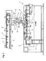
- the drawings show an apparatus for forming and packaging individual portions of fibrous material, in this case cut tobacco.
- This comprises a device 10 (FIG. Fig.1 ), in which individual portions 13 of the fibrous material are formed and a packaging machine 11 - in the present case a so-called bag packer - in which the fibrous material in packaging units 40, in this case tobacco bag, is packaged.
- a packaging machine 11 - in the present case a so-called bag packer - in which the fibrous material in packaging units 40, in this case tobacco bag, is packaged.
- the individual portions 13 are transported in receptacles 14 of an (endless) conveyor 12, in this case in cups of a cup conveyor, especially a cup conveyor.
- the device 10 for forming the Tabakportionen is known per se in the art and, for example in the DE 10 2007 023 511 A1 whose content is incorporated into the present application.
- portioning stations are often referred to as tobacco scales.
- the tobacco stream leaving the dissolving drum 17 is hereby divided in a manner not described in detail, and the individual partial streams are subsequently fed to the portioning stations 15 and 16, namely storage containers 18 arranged above the conveyor 12.
- a tobacco fleece is first formed from the tobacco of the reservoir 18 by converging design of the conveyor in the downward direction and by further, not further explained measures, followed by a tobacco rod, which in the conveyor shaft 19 in Vertical direction is conveyed down.
- the tobacco rod emerging at the lower end of the conveying shaft 19 then passes into the region of a separating device 20.
- this separating device 20 By means of this separating device 20 individual coarse portions of tobacco are separated to form the later individual tobacco portions. These coarse portions are generally underweight to a target weight to be achieved.
- the separating device 20 has separating combs entering the tobacco strands from the sides in each case.
- the reservoir 18, the conveyor shaft 19 and the separator 20 may be formed, for example, as in the DE 33 16 176 A1 described.
- the coarse portions are each fed to a central intermediate conveying member 21, in this case a rotatable about a horizontal axis rotary feeder with a plurality, in this case three mutually offset by 120 ° in the circumferential direction cells 21.1-21.3 for receiving tobacco portions.
- the cells or pockets 20.1-20.3 are open on their radially outward sides.
- the intermediate conveyor 21 has different operating states depending on the rotational position. In each case one of the positions 20.1-20.3 pointing upwards in each of these positions is filled in three upward positions. In each case directed obliquely downwards or to the side alternative positions, the tobacco coarse serving can escape from the respective cell by their own weight.
- the coarse portion of tobacco positioned in the corresponding cell 21.1-21.3 is conveyed into a weighing device 22, 23 of a weighing device 24, each of which is laterally offset below the intermediate conveyor element 21 and also designed as cell wheels.
- the individual weighing elements 22, 23 have, like the intermediate conveying element 21, in each case a plurality of cells for receiving the tobacco coarse portion which is in each case conveyed by the intermediate conveying element 21. Functionally, they are identical to the intermediate conveyor 21.
- the weighing means 22, 23 are arranged laterally offset below the intermediate conveyor 21 in such a way that a coarse portion sliding out of a cell of the intermediate conveyor 21 which points obliquely downwards depending on the position falls into an upwardly pointing cell of the weighing element 22 or 23.
- the weighing elements 22, 23 cooperate with balances 25, 26 assigned to them in each case.
- the carriages 25, 26, respectively the weights or masses of the individual tobacco portions can be determined, which are positioned in the upwardly directed cell of the respective weighing element 22, 23.
- Each Feindos mecanicsaggregat 27, 28 in this case has an obliquely downwardly directed band, is supplied via the supplied from the reservoir 18 via feed chutes 29 and 30 fed fine tobacco a first spiked roller.
- This spiked roller takes over the tobacco and works with a second spiked roller to form a uniform as possible tobacco layer on the first spiked roller together.
- the tobacco layer is lifted from the spiked roller and added in not described manner here of the arranged in the corresponding upward cell of the weighing member 22 and 23 coarse portion.
- the fine portioning namely the addition of further fine tobacco, takes place until the Target weight or the target mass is reached, therefore, the coarse portion can be classified as a good portion.
- a wide variety of conditions can be stored in the controller 50 of the device 10, to which the weighed product portions must comply in order to be classified as a good portion, for example target mass limit values, intervals or the like.
- the mass of the coarse portion separated by the separating device 20 is likewise determined in the weighing elements 22 and 23.
- the mass of the coarse portion does not correspond to predetermined conditions, in particular is greater than the maximum mass prescribed for a single portion, the coarse portion is discharged, ie not used further.
- the respective individual portion 15, which is conveyed via the conveyor 12 in the direction of the packaging machine 11, corresponds to the coarse portion separated at the beginning of the portioning.
- the method of fine portioning to achieve a target weight is indeed more accurate, but on average also more time consuming than the method of coarse portioning.
- the Gutportionen be conveyed via the feeders 31, 32 each have a central, arranged above two filling lines distributor.
- the Gutportionen that originate from the weighing member 22, 23 are cyclically filled in the receptacles 14 of the conveyor 12 via the filling lines, which are designed as filling shafts and transported away.
- the conveyor 12 is designed here as a double-cup chain conveyor, i. in each case two parallel rows 12a, 12b of successively arranged as a cup receptacle 14 are present. On lines transverse to the conveying direction two receptacle or cup 14 are arranged in pairs.
- Each receiving row 12a, 12b are assigned four filling lines, namely two filling lines of the portioning station 15 and two filling lines of the portioning station 16.
- Fig. 1 only the front filling lines are visible in each case, which fill the front intake row 12a with individual portions 13.
- the rear intake row 12b is filled with individual portions 13 by likewise four filling lines, thus two filling lines of the portioning station 15 and two filling lines of the portioning station 16.
- the conveyor 12 has to form the parallel tracks 12a, 12b of receptacles 14 a plurality of parallel, endless conveyor members, which are presently designed as endless chains, and to which the receptacles or cups 14 are attached.
- the chains or the receiving tracks 12a, 12b and the corresponding receptacles 14 associated with the respective receiving tracks run parallel and at a distance from one another to form an upper conveying run 33 and a lower conveying run 34.
- the conveyor 12 or the two receiving tracks extend in the region of the two Portioning stations 15, 16 below the filling lines horizontally.
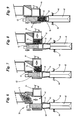
- a discharge or emptying station 35 the receptacles 14 filled with the individual portions 13 are automatically emptied by tilting them, cf. especially Fig. 4 ,
- the mechanisms suitable for such automatic evacuation are known in the art.
- each pair of receptacles 14 located at the unloading station 35 takes place in each case in a distribution station 36.
- the distributor station 36 delivers the individual portions 13 originating from the emptied receptacles 14 either to a store 37 in which the portions are temporarily stored for a certain period of time or directly to a pressing station 38 arranged downstream thereof, in this case below.
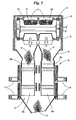
- the distribution station 36 has a housing 54 with two upper funnel-shaped portions, which is arranged in each case in the region of the unloading station 35 under the unloading station 35 associated portion of the lower conveying run 34 of the conveyor 12. Underneath the funnel-shaped sections, a pair of distributor elements 39a, 39b of the distribution station 36, which are positioned one behind the other (transversely to the conveying direction), are again arranged in the housing 54.
- each distributor element 39a, 39b is designed as a cellular wheel which can be rotated about a horizontal axis, with cells 39.1-39.3, each offset by 120 ° in the circumferential direction, for receiving the individual tobacco portions 13.
- Each distributor element 39a, 39b of the distributor element pair is in each case assigned to a row of parallel arranged above the same receiving rows 12a, 12b of the conveyor 12 and the respective arranged in the unloading station 35 receptacle 14 of the associated recording series 12a, 12b.
- the assignment is such that the individual portions 13 of the front picking 12a of the conveyor 12 at the unloading station 35 gravity fall along the respective funnel-shaped upper housing portion 54 in the upward facing cell 39.1-39.3 of immediately below this row 12a arranged according to front manifold 39a can.
- the individual tobacco portions 13 of the rear intake row 12b can fall into the respectively upwardly facing cell 39.1-39.3 of the rear distributor element 39b.
- the individual portions 13 conveyed in the receptacles 14 are combined and filled as a filling portion from a plurality of individual portions 13 into the waiting packaging units 40, in the present case tobacco pouches.
- the individual portions 13 are fed to the pressing station 38 and are pressed together there to form a filling portion ( Fig. 6-9 ).
- the individual portions 13 fall by gravity into a pressing chamber 41 of the pressing station 38.
- the pressing chamber 41 is bounded on one side by a vertically motor reciprocating closure member 42 which can close an opening 43 in the bottom of the pressing chamber 41.
- a pressing part 44 which can also be moved horizontally likewise by way of a motor limits the pressing chamber 41.
- the pressing member 44 moves toward the closing member 42.
- the volume between closure member 42 and pressing member 44 is thereby reduced and the individual portions 13 are pressed into the filling portion.
- the pressing movement of the pressing part 44 is superimposed on a movement of the closure member 42 from the position in which the pressing chamber opening 43 is closed ( Fig. 6 ), first upwards ( Fig. 7, 8 ). Finally, in a return movement of the closure member 42 down ( Fig. 9 ) the filling portion of individual portions 13 from above through the closure member 42 and pushed from the compression chamber opening 43 down through an underlying funnel 45 into a below the funnel 45 by the bag packer 11 held ready bag 40.
- a respective upright bag 40 of a row of bags 40 guided past the funnel 45 is positioned in a cyclic manner by means of a suitable horizontal conveyor of the bag packer 11 and held there. Once a bag 40 is positioned immediately below the hopper 45, the filling portion is filled in the respective bag 40.
- the bags 40 are first fed in a scale-like formation by means of a feeding belt 52 to a bag erector 53, which singulates and straightens the bags 40. In the further course, they are pulled apart by suction elements 46 acting on their respective front and rear sides, so that an upper filling opening of the bag 40 is opened. Also at the filling position at which the bags 40 are each filled with the filling portion, are respectively the front and back of the bag 40 acting on suction organs 46, which hold the bag 40 in its open position.
- the bags 40 are transported further after the filling process and closed and welded at subsequent closing and welding stations 47. Subsequently, the bags are removed by means of a conveyor 48.
- the distribution station 36 - as already indicated above - also has a memory 37.
- this comprises two storage elements 49a, 49b arranged laterally offset below the distributor elements 39a, 39b, here likewise driven as drive units 51, and in the form of cell wheels rotatable about a horizontal axis in the present case.
- Each cell wheel like the cell wheels of the distributor elements 39a, 39b, has cells 49.1-49.3, each offset by 120 ° in the circumferential direction, for receiving tobacco portions.
- the cells 49.1-49.3 are open on their radially outer sides.
- the upwardly facing cells 49.1-49.3 are filled.
- the cellular wheels and other distribution organs could be used, such as organs with floating flaps or the like.
- the two storage members 49a, 49b are disposed within the housing 54 of the distribution station 36 and each independently drivable or rotatable.
- the contour of the housing 54 is adapted to the storage organs 49a, 49b such that the respective obliquely downward or obliquely to the side, namely in the direction of the housing wall of the housing 54 facing or opened cell 49.1-49.3 together with the adjacent housing wall a storage space forms.
- Each cell wheel has two cells 49.1-49.3, in which individual portions 13 can be stored. This is in addition to the described cell 49.1-49.3, which points obliquely down to the housing wall 54, the cell 49.1-49.3, which is directed upward. Individual portions 13 in turn, which are in the obliquely downward, but away from the housing wall facing cell 49.1-49.3 are ejected by their own weight from the cell 49.1-49.3 and fall into the pressing chamber 41st
- the front accumulator 49a is associated with the front manifold 39a, the rear accumulator 49b with the rear manifold 39b.
- the distributor elements 39a, 39b can transfer individual portions 13 to the storage elements 49a, 49b.
- the distributor elements 39a, 39b have to be rotated in a second direction opposite to the first direction, in each case in the clockwise direction.
- the individual portions 13 are then temporarily stored in the memory 37 and unloaded as needed in the pressing chamber 41, preferably by rotation in the first direction and counterclockwise.
- the memory 37 enables the production of filling portions which do not conform to the above pattern n * 2 but follow the pattern (2 * n + 1), where n is an even number greater than or equal to 1.
- filling portions can then be produced from an odd number of individual portions 13, for example from 3, 5, 7 etc. filling portions.
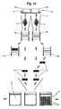
- Fig. 10 schematically shows the procedure for producing a filling portion of an odd number of individual portions 13, namely five individual portions shown.
- the pressing chamber 41 has been omitted.
- both individual portions 13 of a first pair of receptacles 14 a, 14 b directly, d. H. without caching, discharged into the pressing chamber 41 by rotating the distributing members 39a, 39b counterclockwise so that the single portions 13 fall directly into the pressing chamber 41.
- the individual portions 13 of the next pair of receptacles are moved. At this time, there are then four individual portions 13 in the pressing chamber 41.
- the two portions 13 of the next following pair of receptacles are then transferred by rotation of the distributor elements 39a, 39b in the second direction or clockwise to the two storage members 49a, 49b of the memory 37.
- the single portion 13 still located in the second storage element 49a will then be added to the individual portions 13 of the two previous receiving pairs.
- the total mass of the (n-1) individual portions is determined by adding the measured individual masses.
- a further single portion 13 is then finely portioned.
- the mass of this finely portioned individual portion 13 is metered such that the mass of coarse portioned individual portions, the mass m Boardportion results in the filling material portion to be formed together with the total mass of the (n-1), at least approximately, preferably exactly.
- the so portioned individual portions 13 are individually transferred to the conveyor 12 and tracked during the conveying movement, for example by means of shift registers, so that it is known which individual portions 13 are each in which receptacle 14.
- the individual portions 13 tracked in this manner are then filled together into the pressing chamber 41 to form the contents of the contents, if necessary using the memory 37, pressed together and filled into a bag 40 which is kept ready.
- Fig. 11 Finally shows in the controller 50 of the system stored relationships for the example case that at maximum single serving masses of 50g, which can produce the Portionier wornen 15, 16, a Brownportion the mass e G to be produced.
- the filling portion e G is to be 160 g
- the quotient of the desired filling portion e G and the maximum individual portion mass of 50 g must be formed. This quotient is rounded up to the value y, namely the next largest integer value. In the present case, y would assume the value 4.
- the mass (in grams) of the necessary to achieve the desired filling portion Calculate single portions G P , then the quotient of the desired Greportionsmassen e G and y must be formed. In the present case G P would be 40g.
- the present invention is by no means limited to the present application example.
- other types of packaging units may be used, such as cans or the like.
- the compression of the individual portions to summarize a filling portion although useful, but not mandatory.
- all units, in particular the distribution station, the pressing station, the portioning stations, the memory, etc. can basically be designed in a different way or individual method steps can deviate from the exemplary embodiment.
Description
Die Erfindung betrifft ein Verfahren zur Bildung und Verpackung von Portionen aus faserigem Gut, nämlich Tabak, bei dem aus dem faserigen Gut gebildete Einzelportionen des faserigen Guts mit einem Förder einzeln in Richtung einer Maschine zur Verpackung der Einzelportionen in Verpackungseinheiten, nämlich Tabakbeutel, gefördert werden. Die Erfindung betrifft des Weiteren eine Vorrichtung zur Durchführung des Verfahrens.The invention relates to a method for the formation and packaging of portions of fibrous material, namely tobacco, in which formed from the fibrous material individual portions of the fibrous material with a conveyor individually in the direction of a machine for packaging the individual portions in packaging units, namely tobacco pouches promoted. The invention further relates to a device for carrying out the method.
Eine Vorrichtung, die nach einem derartigen Verfahren arbeitet, ist beispielsweise in der
Die in der Tabakindustrie gängigen Portioniereinrichtungen können jeweils nur Tabakportionen bestimmter Maximalmenge bzw. Maximalmasse bilden. In der Regel sind 50g-Portionen die Obergrenze. Für darüber hinaus gehende Portionsmengen, etwa 100g-Portionen, müssten die Portioniereinrichtungen aufwändig und kostenintensiv umkonstruiert werden.The usual in the tobacco industry portioning can each form only tobacco portions of certain maximum amount or maximum mass. As a rule, 50g portions are the upper limit. For more portioned portions, about 100g portions, the portioning would have to be redesigned consuming and costly.
Ausgehend hiervon ist es Aufgabe der vorliegenden Erfindung, ein Verfahren anzugeben, mit dem ausgehend von von Portioniereinrichtungen vorgegebenen Maximalmassen, die von diesen gebildete Einzelportionen des faserigen Guts aufweisen, Verpackungseinheiten hergestellt werden können, die eine gegenüber dieser Maximalmenge größere Menge an Füllgut aufweisen. Des Weiteren ist es Aufgabe der vorliegenden Erfindung, eine Vorrichtung zur Durchführung dieses Verfahrens anzugeben.Proceeding from this, it is an object of the present invention to provide a method with which, starting from predetermined by portioning maximum masses having formed by these individual portions of the fibrous Guts, packaging units can be produced which have a relation to this maximum amount larger amount of contents. Furthermore, it is an object of the present invention to provide an apparatus for carrying out this method.
Die Aufgabe wird gelöst durch ein Verfahren mit den Merkmalen des Anspruchs 1 sowie durch eine Vorrichtung mit den Merkmalen des Anspruchs 10.The object is achieved by a method having the features of claim 1 and by a device having the features of
Erfindungsgemäß werden demnach mehrere der durch den Förderer geförderten Einzelportionen jeweils zu einer Füllportion zusammengefasst, die dann in die Verpackungseinheit gefüllt wird. Beispielsweise bei einem Förderer mit einzelnen Aufnahmen für die Einzelportionen, etwa einem Becherförderer, werden die Einzelportionen in Richtung des Beutelpackers gefördert und, anders als im Stand der Technik, nicht einzeln in die Beutel gefüllt, sondern zu einer größeren bzw. schwereren Füllportion zusammengefasst. So könnten jeweils zwei Einzelportionen zu einer Füllportion doppelter Menge, drei Einzelportionen zu einer Füllportion dreifacher, vier Einzelportionen zu einer Füllportion vierfacher Menge etc. zusammengefasst und in den jeweiligen Beutel gefüllt werden. Die die Füllportion ergebende Anzahl von Einzelportionen wird stromab des Förderers einer Pressstation zugeführt, in der die Einzelportionen miteinander verpresst werden, bevor sie als Füllportion in die ihnen zugeordnete Verpackungseinheit gefüllt werden.According to the invention, several of the individual portions conveyed by the conveyor are combined to form a filling portion, which is then filled into the packaging unit. For example, in a conveyor with individual receptacles for the individual portions, such as a cup conveyor, the individual portions are conveyed in the direction of the bag packer and, unlike in the prior art, not individually filled in the bag, but combined into a larger or heavier Füllportion. Thus, in each case two individual portions could be combined into a filling portion of double quantity, three individual portions to a filling portion of three times, four individual portions to a filling portion of four times the quantity, etc., and filled into the respective bag. The filling portion resulting number of individual portions is supplied downstream of the conveyor of a pressing station in which the individual portions are pressed together before they are filled as Füllportion in their associated packaging unit.
Weitere Merkmale der vorliegenden Erfindung ergeben sich aus den beigefügten Patentansprüchen, der nachfolgenden Beschreibung eines bevorzugten Ausführungsbeispieles sowie aus den beigefügten Zeichnungen.Further features of the present invention will become apparent from the appended claims, the following description of a preferred embodiment and from the accompanying drawings.
Darin zeigen:
- Fig. 1
- eine Gesamtansicht einer Anlage zur Bildung und Verpackung von Tabakportionen,
- Fig. 2
- die Einzelheit II aus
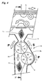
Fig. 1 in vergrößerter Darstellung, nämlich einen Teilbereich der Anlage ausFig. 1 in Seitenansicht, in dem Tabak-Einzelportionen aus den Aufnahmen eines Becherförderers über eine Verteilerstation mit Speicher in eine Pressstation mit Presskammer gefördert werden, dort zu einer Füllportion miteinander verpresst und anschließend mithilfe eines Beutelpackers in Tabakbeutel gefüllt werden, - Fig. 3
- einen Teilbereich der Darstellung aus
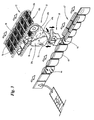
Fig. 2 in Schrägansicht, insbesondere einen Endabschnitt des Becherförderers, die Verteilerstation, die Pressstation sowie eine Reihe von Tabakbeuteln, die mit den Füllportionen befüllt werden, - Fig. 4
- die Einzelheit IV aus
Fig. 2 in vergrößerter Darstellung, - Fig. 5
- einen Schnitt durch die Darstellung gemäß
Fig. 4 entlang der Schnittlinie V-V, - Fig. 6 - 9
- einen Schnitt durch die Darstellung aus
Fig. 2 entlang der Schnittlinie VI-VI, - Fig. 10
- eine schematische Darstellung der Entleerung der Becher des Becherförderers einerseits in den Speicher der Verteilerstation, andererseits direkt in die Presskammer der Pressstation, sowie der nachfolgenden Befüllung der Tabakbeutel,
- Fig. 11
- ein Ablaufdiagramm zur Berechnung der für eine vorbestimmte Füllportion notwendigen Masse der Einzelportionen.
- Fig. 1
- an overall view of a plant for the formation and packaging of tobacco portions,
- Fig. 2
- detail II
Fig. 1 in an enlarged view, namely a portion of the plantFig. 1 in side view, in the tobacco individual portions of the recordings of a cup conveyor via a distribution station with memory in a pressing station with pressing chamber be promoted there, pressed together to form a filling portion and then filled with a bag packer in tobacco pouches, - Fig. 3
- a subarea of the representation
Fig. 2 in an oblique view, in particular an end portion of the bucket conveyor, the distribution station, the pressing station and a number of tobacco pouches, which are filled with the filling portions, - Fig. 4
- the detail IV
Fig. 2 in an enlarged view, - Fig. 5
- a section through the illustration according to
Fig. 4 along the section line VV, - Fig. 6-9
- a section through the representation
Fig. 2 along the section line VI-VI, - Fig. 10
- a schematic representation of the emptying of the cups of the cup conveyor on the one hand in the memory of the distribution station, on the other hand directly into the pressing chamber of the pressing station, and the subsequent filling of the tobacco bag,
- Fig. 11
- a flowchart for calculating the necessary for a predetermined Füllportion mass of the individual portions.
Die Zeichnungen zeigen eine Anlage zur Bildung und Verpackung von einzelnen Portionen aus faserigem Gut, in diesem Fall Schnitt-Tabak.The drawings show an apparatus for forming and packaging individual portions of fibrous material, in this case cut tobacco.
Diese umfasst eine Vorrichtung 10 (
Die Vorrichtung 10 zur Bildung der Tabakportionen ist im Stand der Technik an sich bekannt und beispielsweise in der
Sie weist vorliegend zwei Portioniereinrichtungen bzw. -stationen 15, 16 auf, an denen aus einer Lösetrommel 17 zugeführter Tabak gewogen, portioniert und in die nach oben offenen Aufnahmen bzw. Becher 14 des Förderers 12 gefüllt wird. Solche Portionierstationen werden häufig auch als Tabakwaagen bezeichnet.In the present case, it has two portioning devices or
Der aus der Lösetrommel 17 austretende Tabakstrom wird dabei in nicht näher beschriebener Weise geteilt, und die einzelnen Teilströme anschließend den Portionierstationen 15 bzw. 16 zugeführt, nämlich oberhalb des Förderers 12 angeordneten Vorratsbehältern 18.The tobacco stream leaving the dissolving drum 17 is hereby divided in a manner not described in detail, and the individual partial streams are subsequently fed to the portioning
Die technischen Funktionen und Merkmale der beiden Portionierstationen 15, 16 werden im Folgenden exemplarisch - soweit übereinstimmend - anhand der Portionierstation 15 beschrieben.The technical functions and features of the two
Innerhalb des Vorratsbehälters 18 bzw. innerhalb eines aufrechten Förderschachtes 19 wird aus dem Tabak des Vorratsbehälters 18 durch konvergierende Gestaltung der Förderbahn in Abwärtsrichtung und durch weitere, hier nicht näher erläuterte Maßnahmen, zunächst ein Tabakvlies gebildet und anschließend ein Tabakstrang, der in dem Förderschacht 19 in Vertikalrichtung nach unten gefördert wird.Within the
Der an dem unteren Ende des Förderschachtes 19 austretende Tabakstrang gelangt anschließend in den Bereich einer Trennvorrichtung 20.The tobacco rod emerging at the lower end of the conveying
Mittels dieser Trennvorrichtung 20 werden zur Bildung der späteren Tabak-Einzelportionen einzelne Grobportionen Tabak abgetrennt. Diese Grobportionen sind in der Regel gegenüber einem zu erreichenden Soll-Gewicht untergewichtig. Die Trennvorrichtung 20 weist jeweils von den Seiten her in die Tabakstränge eintretende Trennkämme auf. Der Vorratsbehälter 18, der Förderschacht 19 sowie die Trennvorrichtung 20 können dabei beispielsweise so ausgebildet sein wie in der
Die Grobportionen werden jeweils einem zentralen Zwischenförderorgan 21 zugeführt, im vorliegenden Fall einem um eine horizontale Drehachse drehbaren Zellenrad mit mehreren, vorliegend drei um jeweils um 120° in Umfangsrichtung zueinander versetzten Zellen 21.1-21.3 zur Aufnahme von Tabakportionen. Die Zellen oder Taschen 20.1-20.3 sind auf deren in Radialrichtung außenliegenden Seiten offen. Das Zwischenförderorgan 21 weist je nach Drehposition verschiedene Betriebszustände auf. In drei nach oben gerichteten Positionen wird jeweils eine der in diesen Positionen jeweils nach oben zeigenden Zellen 20.1-20.3 befüllt. In jeweils schräg nach unten bzw. zur Seite gerichteten Alternativstellungen kann die Tabak-Grobportion durch deren Eigengewicht aus der jeweiligen Zelle entweichen.The coarse portions are each fed to a central intermediate conveying
Je nach Drehrichtung wird die in der entsprechenden Zelle 21.1-21.3 positionierte Grobportion Tabak in eines von jeweils seitlich versetzt unterhalb des Zwischenförderorgans 21 angeordneten, vorliegend ebenfalls als Zellenräder ausgebildeten Wiegeorganen 22, 23 einer Wägeeinrichtung 24 gefördert. Die einzelnen Wiegeorgane 22, 23 weisen - wie das Zwischenförderorgan 21 - jeweils mehrere Zellen auf zur Aufnahme der jeweils von dem Zwischenförderorgan 21 zugeförderten Tabak-Grobportion. Funktional sind sie identisch zu dem Zwischenförderorgan 21 ausgebildet. Die Wiegeorgane 22, 23 sind dabei derart seitlich versetzt unterhalb des Zwischenförderers 21 angeordnet, dass eine aus einer je nach Position nach schräg unten weisenden Zelle des Zwischenförderers 21 herausgleitende Grobportion in eine nach oben zeigende Zelle des Wiegeorgans 22 oder 23 fällt.Depending on the direction of rotation, the coarse portion of tobacco positioned in the corresponding cell 21.1-21.3 is conveyed into a weighing
Die Wiegeorgane 22, 23 wirken darüber hinaus jeweils mit jeweils ihnen zugeordneten Waagen 25, 26 zusammen. Mit Hilfe der Wagen 25, 26 können jeweils die Gewichte bzw. Massen der einzelnen Tabakportionen bestimmt werden, die in der nach oben gerichteten Zelle des jeweiligen Wiegeorgans 22, 23 positioniert sind.In addition, the weighing
Die Steuerung 50 der Vorrichtung 10 ermöglicht im Weiteren grundsätzlich zwei verschiedene Arten, aus den so gebildeten Grobportionen die späteren, mithilfe des Becherförders 12 geförderten Einzelportionen 13 zu bilden:
- Bei einer sogenannten Fein-Portionierung wird - wie angedeutet - zunächst die Masse der jeweiligen Grobportion bestimmt. Sollte diese vorbestimmte Bedingungen nicht erfüllen, beispielsweise insbesondere eine geringere Masse aufweisen als eine vorbestimmte SollMasse, wird der Tabakgrobportion zusätzlicher Tabak hinzugefügt, und zwar über entsprechende Feindosierungsaggregate 27, 28.
- In a so-called fine portioning - as indicated - first determines the mass of the respective coarse portion. If these predetermined conditions do not meet, for example, in particular have a lower mass than a predetermined target mass, the tobacco coarse portion additional tobacco is added, via corresponding
fine metering units 27, 28th
Jedes Feindosierungsaggregat 27, 28 weist dabei ein schräg nach unten gerichtetes Band auf, über das aus dem Vorratsbehälter 18 über Zuführschächte 29 bzw. 30 zugeführter Feintabak einer ersten Stachelwalze zugeführt wird. Diese Stachelwalze übernimmt den Tabak und arbeitet mit einer zweiten Stachelwalze zur Bildung einer möglichst gleichmäßigen Tabaklage auf der ersten Stachelwalze zusammen. Durch ein nachfolgendes Stachelrad wird die Tabaklage von der Stachelwalze abgehoben und in hier nicht näher beschriebener Weise der in der entsprechenden, nach oben gerichteten Zelle des Wiegeorgans 22 bzw. 23 angeordneten Grobportion hinzugefügt. Die Feinportionierung, nämlich das Hinzufügen von weiterem Feintabak, erfolgt, bis das Sollgewicht bzw. die Sollmasse erreicht ist, mithin die Grobportion als Gutportion klassifiziert werden kann.Each
Dabei können in der Steuerung 50 der Vorrichtung 10 verschiedenste Bedingungen hinterlegt sein, dem die abgewogenen Gutportionen genügen müssen, um als Gutportion klassifiziert zu werden, beispielsweise Sollmassengrenzwerte, -intervalle oder dergleichen.In this case, a wide variety of conditions can be stored in the
Bei der Alternative zu der beschriebenen Fein-Portionierung, nämlich einer Grob-Portionierung, wird in den Wiegeorganen 22 bzw. 23 ebenfalls die Masse der durch die Trennvorrichtung 20 abgetrennten Grobportion bestimmt. Allerdings wird - anders als bei der oben beschriebenen Fein-Portionierung - darauf verzichtet, der Grobportion über die Feindosierungsaggregate 27, 28 weiteren Tabak hinzuzufügen. Für den Fall, dass die Masse der Grobportion vorbestimmten Bedingungen nicht entspricht, insbesondere größer ist als die für eine Einzelportion vorgeschriebene Maximalmasse, wird die Grobportion ausgeschleust, also nicht weiter verwendet. Ansonsten entspricht die jeweilige Einzelportion 15, die über den Förderer 12 in Richtung der Verpackungsmaschine 11 gefördert wird, der zu Beginn der Portionierung abgetrennten Grobportion.In the alternative to the described fine portioning, namely a coarse portioning, the mass of the coarse portion separated by the separating
Aufgrund des ggf. mehrfachen Hinzufügens von Tabak ist das Verfahren der Fein-Portionierung zur Erreichung eines Sollgewichts zwar genauer, durchschnittlich betrachtet aber auch zeitintensiver als das Verfahren der Grob-Portionierung.Due to the possibly multiple additions of tobacco, the method of fine portioning to achieve a target weight is indeed more accurate, but on average also more time consuming than the method of coarse portioning.
Unabhängig davon, ob das Verfahren der Fein- oder der Grobportionierung angewendet wird, wird nach der Klassifizierung einer Portion als Gutportion die nach oben gerichtete Zelle eines der Wiegeorgane 22, 23, in der die jeweilige Gutportion angeordnet ist, derart in Drehung versetzt, dass sie die Gutportion in eine unterhalb des jeweiligen Wiegeorgans 22, 23 angeordnete Zuführung, nämlich aufrechte Zuführschächte 31, 32, entleert.Regardless of whether the method of fine or coarse portioning is applied, after the classification of a portion as Gutportion the upward cell of one of the weighing
Die Gutportionen werden über die Zuführungen 31, 32 jeweils einem zentralen, oberhalb von zwei Befülllinien angeordneten Verteilerorgan zugefördert. Die Gutportionen, die dem Wiegeorgan 22, 23 entstammen, werden über die Befülllinien, die als Befüllungsschächte ausgebildet sind, taktweise in die Aufnahmen 14 des Förderers 12 gefüllt und abtransportiert.The Gutportionen be conveyed via the
Der Förderer 12 ist dabei vorliegend als Doppelbecherkettenförderer ausgebildet, d.h. jeweils zwei parallele Reihen 12a, 12b von hintereinander angeordneten als Becher ausgebildete Aufnahme 14 sind vorhanden. Auf Linien quer zur Förderrichtung sind jeweils paarweise zwei Aufnahme bzw. Becher 14 angeordnet.The
Jeder Aufnahmereihe 12a, 12b sind dabei vier Befülllinien zugeordnet, nämlich zwei Befülllinien der Portionierstation 15 und zwei Befülllinien der Portionierstation 16. In
Der Förderer 12 weist zur Bildung der parallelen Bahnen 12a, 12b von Aufnahmen 14 mehrere parallele, endlose Förderorgane auf, die vorliegend als endlose Ketten ausgebildet sind, und an denen die Aufnahmen bzw. Becher 14 befestigt sind. Die Ketten bzw. die Aufnahmebahnen 12a, 12b sowie die entsprechenden, den jeweiligen Aufnahmebahnen zugeordneten Aufnahmen 14 laufen parallel und mit Abstand voneinander unter Bildung eines oberen Fördertrums 33 und eines unteren Fördertrums 34. Der Förderer 12 bzw. die beiden Aufnahmebahnen verlaufen im Bereich der beiden Portionierstationen 15, 16 unterhalb der Befüllungslinien horizontal.The
In einer Entlade- bzw. Entleerungsstation 35 werden die mit den Einzelportionen 13 gefüllten Aufnahmen 14 durch Kippen derselben selbsttätig entleert, vgl. insbesondere
Die Entleerung des sich jeweils an der Entladestation 35 befindenden Paares von Aufnahmen 14 erfolgt jeweils in eine Verteilerstation 36.The emptying of each pair of
Die Verteilerstation 36 führt die aus den entleerten Aufnahmen 14 stammenden Einzelportionen 13 entweder einem Speicher 37 zu, in der die Portionen einen gewissen Zeitraum zwischengespeichert werden, oder unmittelbar einer stromab derselben, in diesem Fall unterhalb, angeordneten Pressstation 38.The
Die Verteilerstation 36 verfügt über ein Gehäuse 54 mit zwei oberen trichterförmigen Abschnitten, die jeweils im Bereich der Entladestation 35 unter dem der Entladestation 35 zugeordneten Abschnitt des unteren Fördertrums 34 des Förderers 12 angeordnet ist. Unterhalb der trichterförmigen Abschnitte ist in dem Gehäuse 54 wiederum ein Paar von hintereinander (quer zur Förderrichtung) positionierten Verteilerorganen 39a, 39b der Verteilerstation 36 angeordnet.The
Jedes Verteilerorgan 39a, 39b ist vorliegend als hier um eine horizontale Achse drehbares Zellenrad ausgebildet mit jeweils um 120° in Umfangsrichtung zueinander versetzten Zellen 39.1-39.3 zur Aufnahme der Tabak-Einzelportionen 13.In the present case, each
Jedes Verteilerorgan 39a, 39b des Verteilerorganpaares ist dabei jeweils einer Reihe der parallel oberhalb desselben angeordneten Aufnahmereihen 12a, 12b des Förderers 12 zugeordnet bzw. der jeweiligen im Bereich der Entladestation 35 angeordneten Aufnahme 14 der ihm zugeordneten Aufnahmereihe 12a, 12b.Each
Die Zuordnung ist derart, dass die Einzelportionen 13 der vorderen Aufnahmereihe 12a des Förderers 12 an der Entladestation 35 schwerkraftbedingt entlang des jeweiligen trichterförmigen oberen Gehäusebereichs 54 in die nach oben zeigende Zelle 39.1-39.3 des unmittelbar unter dieser Reihe 12a angeordneten, entsprechend vorderen Verteilerorgans 39a fallen können. Entsprechend können die Tabak-Einzelportionen 13 der hinteren Aufnahmereihe 12b in die jeweils nach oben zeigende Zelle 39.1-39.3 des hinteren Verteilerorgans 39b fallen.The assignment is such that the
Durch Drehung der unabhängig voneinander drehbar mittels Antriebsaggregaten 51, insbesondere Elektromotoren, angetriebenen bzw. antreibbaren Verteilerorgane 39a, 39b, in einer ersten Richtung, vorliegend entgegen des Uhrzeigersinns, können die Einzelportionen 13, die beim Entladevorgang in die jeweils obere Zelle 39.1-39.3 des jeweiligen Verteilerorgans 39a, b gefallen sind, in die Pressstation 38 weitergeleitet werden (Pfeilrichtung, insbesondere in
Besonders wesentlich ist, dass erfindungsgemäß mehrere der in den Aufnahmen 14 geförderten Einzelportionen 13 zusammengefasst werden und als Füllportion aus mehreren Einzelportionen 13 in die bereitstehenden Verpackungseinheiten 40, im vorliegenden Fall Tabakbeutel, gefüllt werden. So können beispielsweise jeweils zwei Einzelportionen 13, die sich in den Aufnahmen 14 eines Aufnahmepaares befinden, der Pressstation 38 zugeführt und dort miteinander zu einer Füllportion verpresst werden (
Die Presskammer 41 wird an einer Seite durch ein vertikal motorisch hin- und her bewegbares Verschlussorgan 42 begrenzt, das eine Öffnung 43 im Boden der Presskammer 41 verschließen kann. Auf der anderen Seite der Presskammer 41 begrenzt ein horizontal ebenfalls motorisch hin- und her bewegbares Pressteil 44 die Presskammer 41.The
Zur Verpressung von sich in der Presskammer 41 befindenden Einzelportionen 13 bewegt sich das Pressteil 44 auf das Verschlussorgan 42 zu. Das Volumen zwischen Verschlussorgan 42 und Pressteil 44 wird hierbei verkleinert und die Einzelportionen 13 dabei zu der Füllportion verpresst.For pressing of
Der Pressbewegung des Pressteils 44 überlagert ist eine Bewegung des Verschlussorgans 42 aus der Stellung, in der die Presskammeröffnung 43 verschlossen ist (
Unterhalb des Trichters 45 wird hierbei mittels eines geeigneten Horizontalförderers des Beutelpackers 11 taktweise jeweils ein aufrecht stehender Beutel 40 einer Reihe von unterhalb des Trichters 45 vorbeigeführter Beutel 40 positioniert und dort gehalten. Sobald ein Beutel 40 unmittelbar unter dem Trichter 45 positioniert ist, wird die Füllportion in den jeweiligen Beutel 40 eingefüllt.Below the
Um die Beutel 40 in dieser Weise bereit halten zu können, werden die Beutel 40 zunächst in einer schuppenartigen Formation mittels eines Zuführgurtes 52 einem Beutelaufrichter 53 zugeführt, der die Beutel 40 vereinzelt und aufrichtet. Im weiteren Verlauf werden sie an durch jeweils an ihrer Vorder- und an der Rückseite angreifende Saugorgane 46 auseinandergezogen, so dass eine obere Einfüllöffnung des Beutels 40 geöffnet wird. Auch an der Befüllposition, an der die Beutel 40 jeweils mit der Füllportion befüllt werden, befinden sich jeweils die Vorder- und Rückseite der Beutel 40 beaufschlagende Saugorgane 46, die die Beutel 40 in ihrer geöffneten Stellung halten.In order to be able to hold the
Die Beutel 40 werden nach dem Befüllvorgang weiter transportiert und an nachfolgenden Schließ- und Schweißstationen 47 geschlossen und verschweißt. Anschließend werden die Beutel mittels eines Förderers 48 abtransportiert.The
Auf die geschilderte Weise ist es möglich, beispielsweise zwei, vier, sechs usw. Einzelportionen der Presskammer 41 zuzuführen und dort zu einer Füllportion aus entsprechend zwei, vier, sechs etc. Einzelportionen zu verpressen. Somit können gegenüber dem Stand der Technik größere Füllportionen aus mehreren Einzelportionen hergestellt werden.In the manner described, it is possible, for example, two, four, six, etc. supply individual portions of the
Mit den Portionierstationen des Standes der Technik können ansonsten in der Regel nur Einzelportionen hergestellt werden, die eine bestimmte maximale Menge bzw. Masse aufweisen. In der Regel sind dies 50g. Dementsprechend können auch nur Tabakbeutel mit maximal 50g-Portionen hergestellt werden. Die vorliegende Erfindung ermöglicht es, Tabakbeutel mit vielfachen der von den Portioniereinrichtungen maximal herzustellenden Einzelportionen zu produzieren.As a rule, with the portioning stations of the prior art, only individual portions can be produced which have a certain maximum quantity or mass. In general, this is 50g. Accordingly, only tobacco pouches can be produced with a maximum of 50g portions. The present invention makes it possible to produce tobacco pouches with multiples of the maximum portions to be produced by the portioning devices.
In dem vorliegenden Ausführungsbeispiel weist die Verteilerstation 36 - wie oben bereits angedeutet - zudem einen Speicher 37 auf. Dieser umfasst vorliegend zwei seitlich versetzt unterhalb der Verteilerorgane 39a, 39b angeordnete, hier ebenfalls als durch Antriebsaggregate 51 angetriebene, als vorliegend um eine horizontale Achse drehbare Zellenräder ausgebildete Speicherorgane 49a, 49b. Jedes Zellenrad verfügt wie die Zellenräder der Verteilerorgane 39a, 39b über jeweils um 120° in Umfangsrichtung zueinander versetzte Zellen 49.1-49.3 zur Aufnahme von Tabakportionen. Die Zellen 49.1-49.3 sind auf deren in Radialrichtung außenliegenden Seiten offen. Die jeweils nach oben zeigende Zellen 49.1-49.3 wird befüllt. Anstelle der Zellenräder könnten auch andere Verteilerorgane eingesetzt werden, etwa Organe mit schwebbaren Klappen oder dergleichen.In the present embodiment, the distribution station 36 - as already indicated above - also has a
Die beiden Speicherorgane 49a, 49b sind innerhalb des Gehäuses 54 der Verteilerstation 36 angeordnet und jeweils unabhängig voneinander antreibbar bzw. drehbar. Die Kontur des Gehäuses 54 ist derart an die Speicherorgane 49a, 49b angepasst, dass die jeweils schräg nach unten bzw. schräg zur Seite, nämlich in Richtung der Gehäusewand des Gehäuses 54 zeigende bzw. geöffnete Zelle 49.1-49.3 zusammen mit der angrenzenden Gehäusewand einen Speicherraum bildet.The two
Jedes Zellenrad verfügt über zwei Zellen 49.1-49.3, in denen Einzelportionen 13 gespeichert werden können. Dies ist neben der beschriebenen Zelle 49.1-49.3, die schräg nach unten zur Gehäusewand 54 zeigt, die Zelle 49.1-49.3, die nach oben gerichtet ist. Einzelportionen 13 wiederum, die sich in der schräg nach unten, allerdings von der Gehäusewand weg zeigenden Zelle 49.1-49.3 befinden, werden durch ihr Eigengewicht aus der Zelle 49.1-49.3 ausgeworfen und fallen in die Presskammer 41.Each cell wheel has two cells 49.1-49.3, in which
Das vordere Speicherorgan 49a ist dem vorderen Verteilerorgan 39a zugeordnet, das hintere Speicherorgan 49b dem hinteren Verteilerorgan 39b.The
Die Verteilerorgane 39a, 39b können Einzelportionen 13 an die Speicherorgane 49a, 49b übergeben. Hierzu müssen die Verteilerorgane 39a, 39b in einer zweiten, zur ersten Richtung entgegengesetzten Richtung, vorliegend jeweils im Uhrzeigersinn, gedreht werden. Die Einzelportionen 13 werden dann in dem Speicher 37 zwischengespeichert und bei Bedarf in die Presskammer 41 entladen, bevorzugt durch Drehung in der ersten Richtung bzw. entgegen dem Uhrzeigersinn.The
Die Verwendung des Speichers 37 hat verschiedene Vorteile:
- Falls Füllportionen aus n*2
Einzelportionen 13 gebildet werden sollen, wobei n eine gerade Zahl größer oder gleich 1 ist, ist eineZwischenspeicherung von Einzelportionen 13 beispielsweise dann vorteilhaft, wenn durch beispielsweise einen Fehler inden Portionierstationen Förderers 12 mit einerEinzelportion 13 gefüllt ist. DieseEinzelportion 13 kann dann indem Speicher 37 zwischengespeichert werden, bis zu einem späteren Zeitpunkt durch einen erneuten Fehler wiederum nur eine Aufnahme 14 eines Aufnahmepaares mit einerEinzelportion 13 gefüllt ist. Sobald dann das Aufnahmepaar mit dieser weiteren nur einfach gefüllten Aufnahme 14 indie Presskammer 41 entleert wird, wird zu der Füllportion, die aus dieser Einzelportion 13 gebildet werden soll, dieim Speicher 37 befindliche Einzelportion 13 hinzugegeben. Ohne eine derartige Zwischenspeicherung wäre es in einem solchen Szenario dagegen notwendig, dieEinzelportion 13 eines nur hälftig gefüllten Aufnahmepaares als Fehlportion auszuschleusen.
- If filling portions are to be formed from n * 2
individual portions 13, where n is an even number greater than or equal to 1, intermediate storage ofindividual portions 13 is advantageous, for example, if, for example, an error in the portioningstations recording Receivers 14 of theconveyor 12 is filled with asingle portion 13. Thissingle portion 13 can then be temporarily stored in thememory 37, until at a later time by a renewed error again only ashot 14 of a pair of receptacles with asingle portion 13 is filled. As soon as then the pair of receptacles is emptied into thepressing chamber 41 with this further only simply filledreceptacle 14, thesingle portion 13 located in thestorage 37 is added to the filling portion which is to be formed from thissingle portion 13. Without such caching, however, it would be necessary in such a scenario, auszuschleusen thesingle portion 13 of a half-filled intake pair as a wrong portion.
Weiter ermöglicht der Speicher 37 die Herstellung von Füllportionen, die nicht dem obigen Muster n*2 entsprechen, sondern dem Muster (2*n + 1) folgen, wobei n eine gerade Zahl größer gleich 1 ist.Further, the
Mit anderen Worten können dann Füllportionen aus einer ungeraden Zahl von Einzelportionen 13, etwa aus 3, 5, 7 usw. Füllportionen hergestellt werden.In other words, filling portions can then be produced from an odd number of
In
Zur Erzielung einer Füllportion aus fünf Einzelportionen 13 werden am Ende eines ersten Fördertakts des Förderers 12 beide Einzelportionen 13 eines ersten Aufnahmepaares von Aufnahmen 14a, 14b direkt, d. h. ohne Zwischenspeicherung, in die Presskammer 41 entladen, indem die Verteilerorgane 39a, 39b entgegen des Uhrzeigersinns gedreht werden, so dass die Einzelportionen 13 unmittelbar in die Presskammer 41 fallen. In gleicher Weise wird am Ende des nächsten Fördertakts mit den Einzelportionen 13 des nächsten Aufnahmepaares verfahren. Zu diesem Zeitpunkt befinden sich dann vier Einzelportionen 13 in der Presskammer 41.To achieve a filling portion of five
Die beiden Portionen 13 des nächst folgenden Aufnahmepaares werden dann durch Drehung der Verteilerorgane 39a, 39b in der zweiten Richtung bzw. im Uhrzeigersinn an die beiden Speicherorgane 49a, 49b des Speichers 37 übergeben.The two
Von den beiden Speicherorganen 49a, 49b wird dann im weiteren Verlauf nur eines der Speicherorgane, beispielsweise das Speicherorgan 49b, im Uhrzeigersinn weitergedreht werden, um die in ihm gespeicherte Einzelportion 13 an die Presskammer 41 zu übergeben. Die in dem anderen Speicherorgan 49a befindliche Einzelportion 13 dagegen wird weiter gespeichert bleiben.Of the two
Im Ergebnis werden sich nach drei Fördertakten des Förderers 12 fünf Einzelportionen 13 in der Presskammer 41 befinden. Anschließend werden diese Einzelportionen 13 in der bereits oben beschriebenen Weise zu einer Füllportion verpresst und in die Tabakbeutel 40 eingefüllt.As a result, five
Zur Herstellung der nächsten Füllportion wird dann die sich noch in dem zweiten Speicherorgan 49a befindliche Einzelportion 13 den Einzelportionen 13 der beiden vorherigen Aufnahmepaare hinzugefügt werden.In order to produce the next filling portion, the
In einer weiteren wesentlichen Ausführungsform der Erfindung werden an den Portionierstationen 15, 16 (n-1) Einzelportionen 13, die später zu einer Füllportion der Masse mFüllportion aus n Einzelportionen 13 zusammengefasst werden sollen, in der oben beschriebenen Weise zunächst grob portioniert und gewogen.In a further essential embodiment of the invention, at the portioning
Anschließend wird durch Addition der gemessenen Einzelmassen die Gesamtmasse der (n-1) Einzelportionen ermittelt.Subsequently, the total mass of the (n-1) individual portions is determined by adding the measured individual masses.
In der Portioniereinrichtung 15, 16 wird danach eine weitere Einzelportion 13 fein portioniert. Die Masse dieser fein portionierten Einzelportion 13 wird derart dosiert, dass deren Masse zusammen mit der Gesamtmasse der (n-1) grob portionierten Einzelportionen die Masse mFüllportion die zu bildende Füllgutportion ergibt, zumindest annähernd, vorzugsweise exakt.In the
Anschließend werden die so portionierten Einzelportionen 13 einzeln an den Förderer 12 übergeben und während der Förderbewegung nachverfolgt, beispielsweise mithilfe von Schieberegistern, sodass bekannt ist, welche Einzelportionen 13 sich jeweils in welcher Aufnahme 14 befinden. Die auf diese Weise nachverfolgten Einzelportionen 13 werden zur Bildung der Füllgutportion dann gemeinsam in die Presskammer 41 gefüllt, ggf. unter Verwendung des Speichers 37, miteinander verpresst und in einen bereit gehaltenen Beutel 40 gefüllt.Subsequently, the so portioned
Durch diese Vorgehensweise kann bei hoher Geschwindigkeit der Anlage eine gleichzeitig möglichst geringe Differenz der Füllportionsmassen gegenüber vorgegebenen Sollwerten erreicht werden. Denn obgleich Grobportioniervorgänge hoher Geschwindigkeit ablaufen, entspricht die Genauigkeit der Masse der sich ergebenden Füllportionsmenge im Vergleich zum Sollwert derjenigen, die erreicht würde, würde ausschließlich fein portioniert werden. Es genügt dabei, nur eine der Einzelportionen 13 einer Füllportion auf diese Weise fein zu portionieren, um insgesamt eine Füllportionsmenge zu erhalten, die sehr nah an das Sollgewicht herankommt oder diesem entspricht.As a result of this procedure, at the same time as the system is running at a high speed, it is possible to achieve the smallest possible difference between the filling portion masses and the predetermined setpoint values. For although high speed coarse portioning operations occur, the accuracy of the mass of the resulting pouring portion compared to the desired value of that which would be achieved would be finely portioned only. It suffices to portion in this way finely one of the
Wenn die Füllportion eG beispielsweise 160g betragen soll, muss zunächst der Quotient aus der gewünschten Füllportion eG und der maximalen Einzelportionsmasse von 50g gebildet werden. Dieser Quotient wird aufgerundet auf den Wert y, nämlich den nächstgrößeren ganzzahligen Wert. Im vorliegenden Fall würde y den Wert 4 annehmen. Um die Masse (in Gramm) der zur Erzielung der gewünschten Füllportion notwendigen Einzelportionen GP zu berechnen, muss dann der Quotient aus der gewünschten Füllportionsmassen eG und y gebildet werden. Im vorliegenden Fall wäre GP 40g.If, for example, the filling portion e G is to be 160 g, first the quotient of the desired filling portion e G and the maximum individual portion mass of 50 g must be formed. This quotient is rounded up to the value y, namely the next largest integer value. In the present case, y would assume the value 4. To the mass (in grams) of the necessary to achieve the desired filling portion Calculate single portions G P , then the quotient of the desired Füllportionsmassen e G and y must be formed. In the present case G P would be 40g.
Wie der Fachmann des Standes der Technik erkennt, ist die vorliegende Erfindung keinesfalls auf das vorliegende Anwendungsbeispiel beschränkt. So können beispielsweise andere Arten von Verpackungseinheiten verwendet werden, wie etwa Dosen oder dergleichen. Weiter ist die Verpressung der Einzelportionen zur Zusammenfassung zu einer Füllportion zwar sinnvoll, aber nicht zwingend erforderlich. Insgesamt können sämtliche Aggregate, insbesondere die Verteilerstation, die Pressstation, die Portionierstationen, der Speicher etc. grundsätzlich in abweichender Weise ausgebildet werden bzw. einzelne Verfahrensschritte von dem Ausführungsbeispiel abweichen.As one skilled in the art will recognize, the present invention is by no means limited to the present application example. For example, other types of packaging units may be used, such as cans or the like. Furthermore, the compression of the individual portions to summarize a filling portion, although useful, but not mandatory. Overall, all units, in particular the distribution station, the pressing station, the portioning stations, the memory, etc., can basically be designed in a different way or individual method steps can deviate from the exemplary embodiment.
Claims (13)
- Method of forming and packaging portions (13) of fibrous material, namely tobacco, in which individual portions (13) of the tobacco, which are formed in particular cyclically from the tobacco (13), are conveyed individually by a conveyor (12) in the direction of a machine (11) for packaging the individual portions (13) in packaging units (40), namely tobacco bags, characterized by the following steps:(a) a number of the individual portions (13) conveyed are fed to a pressing station (38), in which the individual portions (13) are pressed together and combined to form a filling portion,(b) in each case one of the filling portions formed in this way is introduced into a respective tobacco bag (40).
- Method according to Claim 1, characterized in that the individual portions (13) are conveyed to the pressing station (38) in individual holders (14) of the conveyor (12), each for a single portion, in particular in the buckets of a bucket conveyor, wherein, in particular at an unloading station (35) assigned to the conveyor (12), the individual portions (13) forming the filling portion x are transferred out of the associated holders (14) of the conveyor (12) into the pressing station (38).
- Method according to one or more of the preceding claims, characterized in that the conveyor (12) has pairs of holders (14) arranged in two parallel rows (12a, 12b) for the individual portions (13), wherein in each case n*2 individual portions (13) from in particular successive n pairs of holders are combined to form a filling portion, where n is a whole number greater than or equal to 1, or wherein in each case n*2 individual portions (13) from in particular successive n pairs of holders are combined with an individual portion (13) from a further pair of holders to form a filling portion, where n is a whole number greater than or equal to 1.
- Method according to one or more of the preceding claims, characterized in that at least one of the individual portions (13) which is to be combined to form a filling portion is removed from a controllable store (37) which has been filled beforehand with one or more individual portions (13), in particular the individual portion (13) from the further pair of holders, which can be added to the n*2 individual portions from the n holders.
- Method according to Claim 4, characterized in that individual portions (13) coming from the holders (14) of the conveyor (12) are fed either to the store (37) or directly to the pressing station (38) by a distributor station (36), in particular at least one distributor mechanism (39a, 39b) of the distributor station (36).
- Method according to one or more of the preceding claims, characterized in that a number of individual portions (13) which corresponds to the filling portion is fed to the pressing station (38) for each pressing operation.
- Method according to Claim 6, characterized in that at least one individual portion (13) from the store (37) is fed to the pressing station (38) for each pressing operation.
- Method according to one or more of the preceding claims, characterized in that the filling portion, following the pressing operation of the individual portions (13), is introduced into an associated tobacco bag (40) supplied in the packaging machine (11), preferably into an in particular upright bag (40) which is open at the top.
- Method according to one or more of the preceding claims, characterized by the following steps:(a) in a portioning device (15, 16), the contents can be portioned precisely into individual portions (13) by a quantity of contents which is established with reference to predetermined criteria being pre-portioned and then weighed, and by the weighed value of the contents mass being compared with a desired value, wherein, in the event of the weighed value falling below the desired value of the pre-portioned quantity, contents are added until the desired value has been reached or exceeded,(b) in the portioning device (15, 16), the contents are portioned roughly into individual portions (13) by a quantity of contents derived with reference to predetermined criteria being portioned only once and then weighed, without this quantity of contents having any further contents added to it,(c) in the portioning device, in the first instance (n-1) individual portions (13) of a filling portion of mass mfilling portion having n individual portions (13), which is to be formed for the respective packaging unit (40), are each portioned roughly and weighed,(d) then the total mass of the (n-1) individual portions (13) is established,(e) in the portioning device (15, 16), a further individual portion (13) is then portioned precisely such that the mass of said further individual portion (13) together with the total mass of the (n-1) roughly portioned individual portions (13) gives at least approximately, preferably precisely, the mass mfilling portion of the contents portion which is to be formed,(f) the portioned individual portions (13) are individually transferred to the conveyor (12) and tracked during the conveying movement,(g) the tracked individual portions (13) are introduced into the packaging unit (40) together, preferably following the pressing operation of the same, in order to form the contents portion.
- Apparatus for forming and packaging portions of fibrous material, namely tobacco, for implementing the method according to Claim 1, having a portioning device (15, 16), which can weigh individual portions (13) of the contents, having a conveyor (12), which can convey the individual portions (13) individually, and having a machine (11) for packaging the individual portions (13) in packaging units (40), namely tobacco bags, characterized in that a number of the individual portions (13) weighed and conveyed can be combined with one another by a pressing operation in a pressing station (38) to form a filling portion, and in that in each case one of the filling portions formed in this way can be introduced into a respective tobacco bag (40).
- Apparatus according to Claim 10, characterized in that the apparatus has a controllable store (37), which can be filled with at least one individual portion (13) and in which the individual portion (13) can be stored on an interim basis.
- Apparatus according to Claim 10 or 11, characterized in that the apparatus has a distributor station (36), which is arranged downstream of the conveyor (12) and in which the individual portions (13) coming from the conveyor (12) can be fed optionally directly to the pressing station (38) or to the store (37).
- Apparatus according to Claim 12, characterized in that the distributor station (36) has at least one distributor mechanism (39) comprising a cellular wheel which is arranged above the pressing station (38) and has at least one cell (39.1-39.3) for accommodating individual portions (13), wherein, depending on the direction of rotation of the cellular wheel, the individual portion (13) arranged in the cell (39.1-39.3) in each case can be transferred either to the store (37), in particular to a cellular wheel of the store (37), or to the pressing station (38).
Priority Applications (1)
| Application Number | Priority Date | Filing Date | Title |
|---|---|---|---|
| PL12004449T PL2546151T3 (en) | 2011-07-13 | 2012-06-13 | Method and device for forming and packaging doses from fibrous material |
Applications Claiming Priority (1)
| Application Number | Priority Date | Filing Date | Title |
|---|---|---|---|
| DE102011107687A DE102011107687A1 (en) | 2011-07-13 | 2011-07-13 | Method and device for forming and packaging portions of fibrous material |
Publications (3)
| Publication Number | Publication Date |
|---|---|
| EP2546151A2 EP2546151A2 (en) | 2013-01-16 |
| EP2546151A3 EP2546151A3 (en) | 2013-04-10 |
| EP2546151B1 true EP2546151B1 (en) | 2014-08-13 |
Family
ID=46384111
Family Applications (1)
| Application Number | Title | Priority Date | Filing Date |
|---|---|---|---|
| EP12004449.0A Not-in-force EP2546151B1 (en) | 2011-07-13 | 2012-06-13 | Method and device for forming and packaging doses from fibrous material |
Country Status (4)
| Country | Link |
|---|---|
| EP (1) | EP2546151B1 (en) |
| DE (1) | DE102011107687A1 (en) |
| DK (1) | DK2546151T3 (en) |
| PL (1) | PL2546151T3 (en) |
Families Citing this family (5)
| Publication number | Priority date | Publication date | Assignee | Title |
|---|---|---|---|---|
| NL2014907B1 (en) * | 2015-06-02 | 2017-01-31 | Sluis Cigar Machinery Bv | Device and method for filling a block-bottom pouch. |
| IT201800003495A1 (en) | 2018-03-13 | 2019-09-13 | Gd Spa | Unit for filling a succession of tubular wrappers for the tobacco industry |
| CN109703800B (en) * | 2019-03-07 | 2021-01-26 | 昆明学院 | Tobacco shred boxing machine |
| CN110395433A (en) * | 2019-08-09 | 2019-11-01 | 王英 | A kind of method for packaging food |
| US11814203B2 (en) | 2021-02-19 | 2023-11-14 | Altria Client Services Llc | Apparatuses and methods for loading containers with products |
Family Cites Families (11)
| Publication number | Priority date | Publication date | Assignee | Title |
|---|---|---|---|---|
| FR1395611A (en) * | 1963-12-26 | 1965-04-16 | Seita | Method and device for constituting equal doses by weight for machines for wrapping tobacco or similar materials |
| DE1432669A1 (en) * | 1964-07-16 | 1969-10-23 | Hauni Werke Koerber & Co Kg | Method for portioning tobacco and apparatus for practicing this method |
| NL139929B (en) * | 1970-11-06 | 1973-10-15 | Erven De Wed J Van Nelle N V D | TOBACCO DOSING DEVICE. |
| GB1427345A (en) * | 1972-08-09 | 1976-03-10 | Douwe Egberts Tabaksmij | Dosing and weighing of cut tobacco |
| DE3226654A1 (en) * | 1982-07-16 | 1984-01-19 | Focke & Co, 2810 Verden | DEVICE AND METHOD FOR PRODUCING TOBACCO PORTIONS |
| JPS5946821A (en) * | 1982-09-11 | 1984-03-16 | Ishida Scales Mfg Co Ltd | Combination weighing method |
| DE3316176A1 (en) | 1983-05-04 | 1984-11-08 | Focke & Co, 27283 Verden | DEVICE FOR EDUCATION AND REMOVAL OF TOBACCO PORTIONS |
| GB8613760D0 (en) * | 1986-06-06 | 1986-07-09 | Fiberglas Canada Inc | Packaging compressible items |
| DE3708078A1 (en) * | 1987-03-13 | 1988-09-22 | Rovema Gmbh | METHOD AND DEVICE FOR THE AUTOMATIC GRAVIMETRIC FILLING OF BULK MATERIAL AND / OR LIQUID |
| JP4069112B2 (en) * | 2004-11-24 | 2008-04-02 | 大和製衡株式会社 | Combination scale |
| DE102007023511A1 (en) | 2007-05-18 | 2008-11-20 | Focke & Co.(Gmbh & Co. Kg) | Method and device for the formation of portions of fibrous material and for the removal of the same |
-
2011
- 2011-07-13 DE DE102011107687A patent/DE102011107687A1/en not_active Withdrawn
-
2012
- 2012-06-13 PL PL12004449T patent/PL2546151T3/en unknown
- 2012-06-13 DK DK12004449.0T patent/DK2546151T3/en active
- 2012-06-13 EP EP12004449.0A patent/EP2546151B1/en not_active Not-in-force
Also Published As
| Publication number | Publication date |
|---|---|
| DE102011107687A1 (en) | 2013-01-17 |
| EP2546151A3 (en) | 2013-04-10 |
| PL2546151T3 (en) | 2015-01-30 |
| DK2546151T3 (en) | 2014-11-17 |
| EP2546151A2 (en) | 2013-01-16 |
Similar Documents
| Publication | Publication Date | Title |
|---|---|---|
| EP1992924B1 (en) | Method and device for forming portions from fibrous material and for transporting said portions | |
| DE102007050268B4 (en) | Device for metered mixing of pourable material components and plastic processing machine | |
| EP2664553B1 (en) | Method for inserting individual products into containers in a robotic line | |
| DE2338374C2 (en) | Method and device for producing individual packaging units from tobacco fibers | |
| EP2546151B1 (en) | Method and device for forming and packaging doses from fibrous material | |
| EP2785594B1 (en) | Packaging machine and method for filling pouches | |
| EP0124740B1 (en) | Device for forming and transporting batches of tobacco | |
| EP0099980B1 (en) | Device for forming tobacco portions | |
| CH437120A (en) | Machine for the fast, gentle conveying of fragile objects, e.g. Eggs, for packing the same | |
| WO2011069578A1 (en) | Device and method for metering planar products | |
| DE602005001032T2 (en) | Apparatus for placing the products in blisters of a blister pack | |
| EP2520497B1 (en) | Method for inserting individual products into containers in a robotic line | |
| EP3197781A2 (en) | Method and device for producing packaging units | |
| EP0979393A1 (en) | Sucrose-n-alkyl asparaginates, production and use thereof | |
| DE2912937C2 (en) | Method and system for forming rubber batches to be fed into a mixer | |
| EP2868211B1 (en) | Portioning device for a machine for the tobacco industry | |
| DE2602564B2 (en) | Device for filling a container with rod-shaped objects | |
| DE2643600C2 (en) | Device for the fully automatic production of multipacks, so-called stick packs, from individually packed confectionery parts | |
| DE202014002777U1 (en) | High-speed product stacking box for the automatic counting and stacking of incoming products and for the further transport of the product stacks in a fan belt with high infeed speed of the products | |
| DE102012002019A1 (en) | Method and device for equalized packaging of bags in a collecting container | |
| EP2807459B1 (en) | Method and device for forming portions of fibrous material and for filling receptacles of a conveyor with the formed portions | |
| EP0326636A1 (en) | Weighing goods feeding apparatus for weigher fillers | |
| DE3048060C2 (en) | Method and device for packaging cotton balls | |
| CH409762A (en) | Device for the market-ready packaging of lumpy goods, in particular fruits | |
| DE1267868B (en) | Method and device for dividing continuously conveyed material |
Legal Events
| Date | Code | Title | Description |
|---|---|---|---|
| PUAI | Public reference made under article 153(3) epc to a published international application that has entered the european phase |
Free format text: ORIGINAL CODE: 0009012 |
|
| AK | Designated contracting states |
Kind code of ref document: A2 Designated state(s): AL AT BE BG CH CY CZ DE DK EE ES FI FR GB GR HR HU IE IS IT LI LT LU LV MC MK MT NL NO PL PT RO RS SE SI SK SM TR |
|
| AX | Request for extension of the european patent |
Extension state: BA ME |
|
| PUAL | Search report despatched |
Free format text: ORIGINAL CODE: 0009013 |
|
| AK | Designated contracting states |
Kind code of ref document: A3 Designated state(s): AL AT BE BG CH CY CZ DE DK EE ES FI FR GB GR HR HU IE IS IT LI LT LU LV MC MK MT NL NO PL PT RO RS SE SI SK SM TR |
|
| AX | Request for extension of the european patent |
Extension state: BA ME |
|
| RIC1 | Information provided on ipc code assigned before grant |
Ipc: B65B 1/04 20060101ALI20130301BHEP Ipc: G01G 17/02 20060101ALN20130301BHEP Ipc: B65B 1/36 20060101ALI20130301BHEP Ipc: A24B 3/00 20060101ALN20130301BHEP Ipc: B65B 63/02 20060101ALN20130301BHEP Ipc: B65B 1/32 20060101AFI20130301BHEP Ipc: B65B 29/00 20060101ALI20130301BHEP Ipc: G01G 13/08 20060101ALN20130301BHEP Ipc: B65B 1/24 20060101ALI20130301BHEP Ipc: B65B 37/18 20060101ALI20130301BHEP Ipc: B65B 59/00 20060101ALN20130301BHEP |
|
| 17P | Request for examination filed |
Effective date: 20131001 |
|
| RBV | Designated contracting states (corrected) |
Designated state(s): AL AT BE BG CH CY CZ DE DK EE ES FI FR GB GR HR HU IE IS IT LI LT LU LV MC MK MT NL NO PL PT RO RS SE SI SK SM TR |
|
| RIC1 | Information provided on ipc code assigned before grant |
Ipc: B65B 1/32 20060101AFI20131025BHEP Ipc: G01G 17/02 20060101ALN20131025BHEP Ipc: A24B 3/00 20060101ALN20131025BHEP Ipc: B65B 59/00 20060101ALN20131025BHEP Ipc: B65B 1/04 20060101ALI20131025BHEP Ipc: B65B 37/18 20060101ALI20131025BHEP Ipc: B65B 1/24 20060101ALI20131025BHEP Ipc: B65B 29/00 20060101ALI20131025BHEP Ipc: B65B 1/36 20060101ALI20131025BHEP Ipc: B65B 63/02 20060101ALN20131025BHEP Ipc: G01G 13/08 20060101ALN20131025BHEP |
|
| RIC1 | Information provided on ipc code assigned before grant |
Ipc: G01G 13/08 20060101ALN20131120BHEP Ipc: B65B 1/24 20060101ALI20131120BHEP Ipc: B65B 63/02 20060101ALN20131120BHEP Ipc: B65B 1/32 20060101AFI20131120BHEP Ipc: B65B 1/04 20060101ALI20131120BHEP Ipc: B65B 59/00 20060101ALN20131120BHEP Ipc: G01G 17/02 20060101ALN20131120BHEP Ipc: B65B 29/00 20060101ALI20131120BHEP Ipc: B65B 37/18 20060101ALI20131120BHEP Ipc: B65B 1/36 20060101ALI20131120BHEP Ipc: A24B 3/00 20060101ALN20131120BHEP |
|
| GRAP | Despatch of communication of intention to grant a patent |
Free format text: ORIGINAL CODE: EPIDOSNIGR1 |
|
| INTG | Intention to grant announced |
Effective date: 20140103 |
|
| GRAS | Grant fee paid |
Free format text: ORIGINAL CODE: EPIDOSNIGR3 |
|
| GRAA | (expected) grant |
Free format text: ORIGINAL CODE: 0009210 |
|
| AK | Designated contracting states |
Kind code of ref document: B1 Designated state(s): AL AT BE BG CH CY CZ DE DK EE ES FI FR GB GR HR HU IE IS IT LI LT LU LV MC MK MT NL NO PL PT RO RS SE SI SK SM TR |
|
| REG | Reference to a national code |
Ref country code: GB Ref legal event code: FG4D Free format text: NOT ENGLISH |
|
| REG | Reference to a national code |
Ref country code: AT Ref legal event code: REF Ref document number: 682041 Country of ref document: AT Kind code of ref document: T Effective date: 20140815 Ref country code: CH Ref legal event code: EP |
|
| REG | Reference to a national code |
Ref country code: IE Ref legal event code: FG4D Free format text: LANGUAGE OF EP DOCUMENT: GERMAN |
|
| REG | Reference to a national code |
Ref country code: DE Ref legal event code: R096 Ref document number: 502012001102 Country of ref document: DE Effective date: 20140925 |
|
| REG | Reference to a national code |
Ref country code: DK Ref legal event code: T3 Effective date: 20141110 |
|
| REG | Reference to a national code |
Ref country code: NL Ref legal event code: T3 |
|
| REG | Reference to a national code |
Ref country code: LT Ref legal event code: MG4D |
|
| PG25 | Lapsed in a contracting state [announced via postgrant information from national office to epo] |
Ref country code: SE Free format text: LAPSE BECAUSE OF FAILURE TO SUBMIT A TRANSLATION OF THE DESCRIPTION OR TO PAY THE FEE WITHIN THE PRESCRIBED TIME-LIMIT Effective date: 20140813 Ref country code: PT Free format text: LAPSE BECAUSE OF FAILURE TO SUBMIT A TRANSLATION OF THE DESCRIPTION OR TO PAY THE FEE WITHIN THE PRESCRIBED TIME-LIMIT Effective date: 20141215 Ref country code: FI Free format text: LAPSE BECAUSE OF FAILURE TO SUBMIT A TRANSLATION OF THE DESCRIPTION OR TO PAY THE FEE WITHIN THE PRESCRIBED TIME-LIMIT Effective date: 20140813 Ref country code: NO Free format text: LAPSE BECAUSE OF FAILURE TO SUBMIT A TRANSLATION OF THE DESCRIPTION OR TO PAY THE FEE WITHIN THE PRESCRIBED TIME-LIMIT Effective date: 20141113 Ref country code: ES Free format text: LAPSE BECAUSE OF FAILURE TO SUBMIT A TRANSLATION OF THE DESCRIPTION OR TO PAY THE FEE WITHIN THE PRESCRIBED TIME-LIMIT Effective date: 20140813 Ref country code: BG Free format text: LAPSE BECAUSE OF FAILURE TO SUBMIT A TRANSLATION OF THE DESCRIPTION OR TO PAY THE FEE WITHIN THE PRESCRIBED TIME-LIMIT Effective date: 20141113 Ref country code: GR Free format text: LAPSE BECAUSE OF FAILURE TO SUBMIT A TRANSLATION OF THE DESCRIPTION OR TO PAY THE FEE WITHIN THE PRESCRIBED TIME-LIMIT Effective date: 20141114 Ref country code: LT Free format text: LAPSE BECAUSE OF FAILURE TO SUBMIT A TRANSLATION OF THE DESCRIPTION OR TO PAY THE FEE WITHIN THE PRESCRIBED TIME-LIMIT Effective date: 20140813 |
|
| REG | Reference to a national code |
Ref country code: PL Ref legal event code: T3 |
|
| PG25 | Lapsed in a contracting state [announced via postgrant information from national office to epo] |
Ref country code: IS Free format text: LAPSE BECAUSE OF FAILURE TO SUBMIT A TRANSLATION OF THE DESCRIPTION OR TO PAY THE FEE WITHIN THE PRESCRIBED TIME-LIMIT Effective date: 20141213 Ref country code: LV Free format text: LAPSE BECAUSE OF FAILURE TO SUBMIT A TRANSLATION OF THE DESCRIPTION OR TO PAY THE FEE WITHIN THE PRESCRIBED TIME-LIMIT Effective date: 20140813 Ref country code: RS Free format text: LAPSE BECAUSE OF FAILURE TO SUBMIT A TRANSLATION OF THE DESCRIPTION OR TO PAY THE FEE WITHIN THE PRESCRIBED TIME-LIMIT Effective date: 20140813 Ref country code: HR Free format text: LAPSE BECAUSE OF FAILURE TO SUBMIT A TRANSLATION OF THE DESCRIPTION OR TO PAY THE FEE WITHIN THE PRESCRIBED TIME-LIMIT Effective date: 20140813 Ref country code: CY Free format text: LAPSE BECAUSE OF FAILURE TO SUBMIT A TRANSLATION OF THE DESCRIPTION OR TO PAY THE FEE WITHIN THE PRESCRIBED TIME-LIMIT Effective date: 20140813 |
|
| PG25 | Lapsed in a contracting state [announced via postgrant information from national office to epo] |
Ref country code: CZ Free format text: LAPSE BECAUSE OF FAILURE TO SUBMIT A TRANSLATION OF THE DESCRIPTION OR TO PAY THE FEE WITHIN THE PRESCRIBED TIME-LIMIT Effective date: 20140813 Ref country code: EE Free format text: LAPSE BECAUSE OF FAILURE TO SUBMIT A TRANSLATION OF THE DESCRIPTION OR TO PAY THE FEE WITHIN THE PRESCRIBED TIME-LIMIT Effective date: 20140813 Ref country code: RO Free format text: LAPSE BECAUSE OF FAILURE TO SUBMIT A TRANSLATION OF THE DESCRIPTION OR TO PAY THE FEE WITHIN THE PRESCRIBED TIME-LIMIT Effective date: 20140813 Ref country code: SK Free format text: LAPSE BECAUSE OF FAILURE TO SUBMIT A TRANSLATION OF THE DESCRIPTION OR TO PAY THE FEE WITHIN THE PRESCRIBED TIME-LIMIT Effective date: 20140813 |
|
| REG | Reference to a national code |
Ref country code: DE Ref legal event code: R026 Ref document number: 502012001102 Country of ref document: DE |
|
| PLBI | Opposition filed |
Free format text: ORIGINAL CODE: 0009260 |
|
| REG | Reference to a national code |
Ref country code: FR Ref legal event code: PLFP Year of fee payment: 4 |
|
| PLAX | Notice of opposition and request to file observation + time limit sent |
Free format text: ORIGINAL CODE: EPIDOSNOBS2 |
|
| 26 | Opposition filed |
Opponent name: G.D SOCIETA PER AZIONI Effective date: 20150511 Opponent name: G.D S.P.A. Effective date: 20150513 |
|
| PLAF | Information modified related to communication of a notice of opposition and request to file observations + time limit |
Free format text: ORIGINAL CODE: EPIDOSCOBS2 |
|
| PG25 | Lapsed in a contracting state [announced via postgrant information from national office to epo] |
Ref country code: SI Free format text: LAPSE BECAUSE OF FAILURE TO SUBMIT A TRANSLATION OF THE DESCRIPTION OR TO PAY THE FEE WITHIN THE PRESCRIBED TIME-LIMIT Effective date: 20140813 |
|
| PLBB | Reply of patent proprietor to notice(s) of opposition received |
Free format text: ORIGINAL CODE: EPIDOSNOBS3 |
|
| PG25 | Lapsed in a contracting state [announced via postgrant information from national office to epo] |
Ref country code: MC Free format text: LAPSE BECAUSE OF FAILURE TO SUBMIT A TRANSLATION OF THE DESCRIPTION OR TO PAY THE FEE WITHIN THE PRESCRIBED TIME-LIMIT Effective date: 20140813 |
|
| REG | Reference to a national code |
Ref country code: CH Ref legal event code: PL |
|
| PG25 | Lapsed in a contracting state [announced via postgrant information from national office to epo] |
Ref country code: CH Free format text: LAPSE BECAUSE OF NON-PAYMENT OF DUE FEES Effective date: 20150630 Ref country code: LI Free format text: LAPSE BECAUSE OF NON-PAYMENT OF DUE FEES Effective date: 20150630 |
|
| REG | Reference to a national code |
Ref country code: FR Ref legal event code: PLFP Year of fee payment: 5 |
|
| PLAY | Examination report in opposition despatched + time limit |
Free format text: ORIGINAL CODE: EPIDOSNORE2 |
|
| PG25 | Lapsed in a contracting state [announced via postgrant information from national office to epo] |
Ref country code: MT Free format text: LAPSE BECAUSE OF FAILURE TO SUBMIT A TRANSLATION OF THE DESCRIPTION OR TO PAY THE FEE WITHIN THE PRESCRIBED TIME-LIMIT Effective date: 20140813 |
|
| PLBC | Reply to examination report in opposition received |
Free format text: ORIGINAL CODE: EPIDOSNORE3 |
|
| REG | Reference to a national code |
Ref country code: FR Ref legal event code: PLFP Year of fee payment: 6 |
|
| PG25 | Lapsed in a contracting state [announced via postgrant information from national office to epo] |
Ref country code: HU Free format text: LAPSE BECAUSE OF FAILURE TO SUBMIT A TRANSLATION OF THE DESCRIPTION OR TO PAY THE FEE WITHIN THE PRESCRIBED TIME-LIMIT; INVALID AB INITIO Effective date: 20120613 Ref country code: SM Free format text: LAPSE BECAUSE OF FAILURE TO SUBMIT A TRANSLATION OF THE DESCRIPTION OR TO PAY THE FEE WITHIN THE PRESCRIBED TIME-LIMIT Effective date: 20140813 |
|
| RDAF | Communication despatched that patent is revoked |
Free format text: ORIGINAL CODE: EPIDOSNREV1 |
|
| PLCK | Communication despatched that opposition was rejected |
Free format text: ORIGINAL CODE: EPIDOSNREJ1 |
|
| REG | Reference to a national code |
Ref country code: DE Ref legal event code: R100 Ref document number: 502012001102 Country of ref document: DE |
|
| PG25 | Lapsed in a contracting state [announced via postgrant information from national office to epo] |
Ref country code: TR Free format text: LAPSE BECAUSE OF FAILURE TO SUBMIT A TRANSLATION OF THE DESCRIPTION OR TO PAY THE FEE WITHIN THE PRESCRIBED TIME-LIMIT Effective date: 20140813 |
|
| PLBN | Opposition rejected |
Free format text: ORIGINAL CODE: 0009273 |
|
| STAA | Information on the status of an ep patent application or granted ep patent |
Free format text: STATUS: OPPOSITION REJECTED |
|
| 27O | Opposition rejected |
Effective date: 20170707 |
|
| REG | Reference to a national code |
Ref country code: FR Ref legal event code: PLFP Year of fee payment: 7 |
|
| PG25 | Lapsed in a contracting state [announced via postgrant information from national office to epo] |
Ref country code: MK Free format text: LAPSE BECAUSE OF FAILURE TO SUBMIT A TRANSLATION OF THE DESCRIPTION OR TO PAY THE FEE WITHIN THE PRESCRIBED TIME-LIMIT Effective date: 20140813 |
|
| PGFP | Annual fee paid to national office [announced via postgrant information from national office to epo] |
Ref country code: LU Payment date: 20180524 Year of fee payment: 7 |
|
| PGFP | Annual fee paid to national office [announced via postgrant information from national office to epo] |
Ref country code: IE Payment date: 20180612 Year of fee payment: 7 Ref country code: DK Payment date: 20180612 Year of fee payment: 7 |
|
| REG | Reference to a national code |
Ref country code: AT Ref legal event code: MM01 Ref document number: 682041 Country of ref document: AT Kind code of ref document: T Effective date: 20170613 |
|
| PGFP | Annual fee paid to national office [announced via postgrant information from national office to epo] |
Ref country code: FR Payment date: 20180529 Year of fee payment: 7 Ref country code: BE Payment date: 20180524 Year of fee payment: 7 |
|
| PG25 | Lapsed in a contracting state [announced via postgrant information from national office to epo] |
Ref country code: AL Free format text: LAPSE BECAUSE OF FAILURE TO SUBMIT A TRANSLATION OF THE DESCRIPTION OR TO PAY THE FEE WITHIN THE PRESCRIBED TIME-LIMIT Effective date: 20140813 |
|
| PGFP | Annual fee paid to national office [announced via postgrant information from national office to epo] |
Ref country code: ES Payment date: 20180702 Year of fee payment: 8 |
|
| PG25 | Lapsed in a contracting state [announced via postgrant information from national office to epo] |
Ref country code: AT Free format text: LAPSE BECAUSE OF NON-PAYMENT OF DUE FEES Effective date: 20170613 |
|
| REG | Reference to a national code |
Ref country code: DK Ref legal event code: EBP Effective date: 20190630 |
|
| GBPC | Gb: european patent ceased through non-payment of renewal fee |
Effective date: 20190613 |
|
| REG | Reference to a national code |
Ref country code: BE Ref legal event code: MM Effective date: 20190630 |
|
| PG25 | Lapsed in a contracting state [announced via postgrant information from national office to epo] |
Ref country code: IE Free format text: LAPSE BECAUSE OF NON-PAYMENT OF DUE FEES Effective date: 20190613 Ref country code: GB Free format text: LAPSE BECAUSE OF NON-PAYMENT OF DUE FEES Effective date: 20190613 |
|
| PG25 | Lapsed in a contracting state [announced via postgrant information from national office to epo] |
Ref country code: BE Free format text: LAPSE BECAUSE OF NON-PAYMENT OF DUE FEES Effective date: 20190630 Ref country code: LU Free format text: LAPSE BECAUSE OF NON-PAYMENT OF DUE FEES Effective date: 20190613 |
|
| PG25 | Lapsed in a contracting state [announced via postgrant information from national office to epo] |
Ref country code: FR Free format text: LAPSE BECAUSE OF NON-PAYMENT OF DUE FEES Effective date: 20190630 |
|
| PG25 | Lapsed in a contracting state [announced via postgrant information from national office to epo] |
Ref country code: DK Free format text: LAPSE BECAUSE OF NON-PAYMENT OF DUE FEES Effective date: 20190630 |
|
| PGFP | Annual fee paid to national office [announced via postgrant information from national office to epo] |
Ref country code: DE Payment date: 20210528 Year of fee payment: 10 Ref country code: NL Payment date: 20210615 Year of fee payment: 10 Ref country code: IT Payment date: 20210526 Year of fee payment: 10 |
|
| PGFP | Annual fee paid to national office [announced via postgrant information from national office to epo] |
Ref country code: PL Payment date: 20210528 Year of fee payment: 10 |
|
| REG | Reference to a national code |
Ref country code: DE Ref legal event code: R119 Ref document number: 502012001102 Country of ref document: DE |
|
| REG | Reference to a national code |
Ref country code: NL Ref legal event code: MM Effective date: 20220701 |
|
| PG25 | Lapsed in a contracting state [announced via postgrant information from national office to epo] |
Ref country code: NL Free format text: LAPSE BECAUSE OF NON-PAYMENT OF DUE FEES Effective date: 20220701 |
|
| PG25 | Lapsed in a contracting state [announced via postgrant information from national office to epo] |
Ref country code: DE Free format text: LAPSE BECAUSE OF NON-PAYMENT OF DUE FEES Effective date: 20230103 |
|
| PG25 | Lapsed in a contracting state [announced via postgrant information from national office to epo] |
Ref country code: IT Free format text: LAPSE BECAUSE OF NON-PAYMENT OF DUE FEES Effective date: 20220613 |
|
| PG25 | Lapsed in a contracting state [announced via postgrant information from national office to epo] |
Ref country code: PL Free format text: LAPSE BECAUSE OF NON-PAYMENT OF DUE FEES Effective date: 20220613 |