EP2545883A2 - Verfahren und Vorrichtung zum Bürsten der Zähne - Google Patents
Verfahren und Vorrichtung zum Bürsten der Zähne Download PDFInfo
- Publication number
- EP2545883A2 EP2545883A2 EP12176303A EP12176303A EP2545883A2 EP 2545883 A2 EP2545883 A2 EP 2545883A2 EP 12176303 A EP12176303 A EP 12176303A EP 12176303 A EP12176303 A EP 12176303A EP 2545883 A2 EP2545883 A2 EP 2545883A2
- Authority
- EP
- European Patent Office
- Prior art keywords
- bristle
- bristle strip
- toothbrush
- strip
- teeth
- Prior art date
- Legal status (The legal status is an assumption and is not a legal conclusion. Google has not performed a legal analysis and makes no representation as to the accuracy of the status listed.)
- Granted
Links
Images


Classifications
-
- A—HUMAN NECESSITIES
- A61—MEDICAL OR VETERINARY SCIENCE; HYGIENE
- A61C—DENTISTRY; APPARATUS OR METHODS FOR ORAL OR DENTAL HYGIENE
- A61C17/00—Devices for cleaning, polishing, rinsing or drying teeth, teeth cavities or prostheses; Saliva removers; Dental appliances for receiving spittle
- A61C17/16—Power-driven cleaning or polishing devices
- A61C17/22—Power-driven cleaning or polishing devices with brushes, cushions, cups, or the like
- A61C17/228—Self-contained intraoral toothbrush, e.g. mouth-guard toothbrush without handle
Definitions
- the present invention relates to a toothbrush that brushes all of a user's teeth simultaneously.
- the toothbrush is an oral hygiene instrument used to remove plaque, clean teeth, and stimulate the gums.
- the standard manual toothbrush consists of a bristled head attached to a handle, wherein the bristled head is only capable of cleaning a small area at a time.
- the recommended way to manually brush teeth is to use the Bass method, whereby the toothbrush is held such that the bristles are angled at a 45 ⁇ angle to the long axis of the tooth and moved back and forth in short, quick strokes. This motion requires a certain level of manual dexterity often absent in the very young, the elderly, and people with physical or mental limitations. Additionally, it is the user's responsibility to ensure that each tooth surface is adequately cleaned.
- An electric toothbrush uses electric power to either move individual bristles ultrasonically or to rapidly move a brush head.
- Electric toothbrushes augment the normal brushing capabilities of a person, and some electric toothbrushes even include a timer feature and/or automatically turn off after a predetermined amount of time to indicate to the user when the appropriate amount of brushing time has lapsed. Although this helps encourage longer brushing times, many users still do not brush for long enough in spite of these aids. Though these capabilities encourage proper brushing, standard electric toothbrushes still require a user to move the toothbrush from tooth to tooth and to manipulate the toothbrush onto the various surfaces of each tooth. As with a manual toothbrush, a person with limited manual dexterity may find using an electric toothbrush difficult or impossible because of the manipulation required to properly reach every tooth surface. This also does not solve the problem of favouring certain teeth or regions of teeth over other teeth or other regions of teeth.
- the Hydrabrush ® (a.k.a. "30 Second Smile") is a multihead brush that engages upper and lower teeth simultaneously. This toothbrush, however, only engages a small number of teeth at any given moment, thus still necessitating a high level of manual dexterity to properly manipulate the handle. Additionally, since the Hydrabrush ® only engages a small number of teeth simultaneously, the time duration necessary to adequately clean all of a user's teeth is still relatively high, as is the likelihood that a user will favour certain tooth regions.
- a person who is rushed, too tired, or physically or mentally impaired may not spend the recommended time brushing his or her teeth. Additionally, he or she may also not be willing or able to adequately manipulate the toothbrush in a manner to effectuate adequate brushing. These deficiencies could result in substandard oral hygiene, potentially risking dental caries and gum disease.
- a toothbrush for engaging substantially all of a user's teeth simultaneously comprising an actuatable bristle strip of a size and dimension to engage substantially all of a user's teeth; a generally U-shaped frame of a size and dimension to fit in a user's mouth, the frame engaging the bristle strip; and an actuation means in communication with the bristle strip for imparting a reciprocating movement to the bristle strip.
- an aperture is provided within the frame to allow the bristle strip to communicate with the actuation means.
- a rigid beam may be attached to the bristle strip, the rigid beam comprising a projection extending outwardly from the bristle strip to engage the actuation means.
- This invention teaches a full mouth toothbrush which allows the brushing of multiple teeth simultaneously. Through use of the full mouth toothbrush, little or no user intervention is required to clean multiple surfaces of multiple teeth simultaneously after the full mouth toothbrush is placed in the mouth of a user. This affords a user with limited dexterity, or someone with limited time or energy, to receive an effective cleaning of his/her teeth for improved dental hygiene.
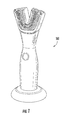
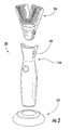
- Figure 2 illustrates an example of a multipart toothbrush 100 construction comprising a handle 210, the handle communicating with a mouthpiece 220, and a charging base 225 in which the handle fits for purposes of recharging and/or storing the toothbrush 100.
- the mouthpiece 220 can be disengaged from the handle 210 to clean and/or replace a worn mouthpiece 220.
- the mouthpiece 220 is ejected from the handle 210 using at least one ejection button 230. This further allows a multitude of users to insert a personal mouthpiece 220 into the handle 210 for use of the device 100.
- the handle 210 is not limited to a specific build, make, or model - nor is it limited to a particular ergonomic shape. However, in this embodiment, the handle 210 is capable of accepting and later removing the mouthpiece 220. Other embodiments (not shown), however, contemplate a unibody construction such that the mouthpiece 220 is rigidly engaged to the handle 210.
- Certain embodiments of the invention contemplate use of the mouthpiece 220 without use or need for a handle 210. Likewise, the invention contemplates a handle 210 which does not require a power source or a motor assembly (described in detail below).
- the handle 210 comprises a handle shell 300, the shell having an end cap 310 that seals the components inside the handle shell 300 from the elements.
- a cap seal 320 maintains a water-tight connection between the handle shell 300 and the end cap 310.
- the cap seal 320 is an o-ring.
- the end cap 310 is threaded, and engages complimentary threads of the handle shell 300.
- the end cap 310 is secured to the handle shell 300 with a fastener 335 which is connected to the chassis 370.
- the handle shell 300 houses a battery 340 that powers a motor 350.
- the motor 350 actuates a gear train 360, the gear train 360 communicating with the mouthpiece 220.
- the battery 340, motor 350, and gear train 360 are mounted to a chassis 370 that engages the handle shell 300.
- the chassis 370 also houses a desiccant 380 for the purpose of reducing moisture levels within the handle shell.
- the toothbrush 100 may rest in the charging base 225 for the purpose of recharging the battery 340.
- the handle shell 300 further comprises a power button 390.
- the power button 390 is not limited to a button, but can be a switch or similar device.
- the charging base 225 has a power cord that plugs into an electrical outlet, which serves to provide power to recharge the battery 340.
- the charging base 225 wirelessly transmits energy through an induction charging coil and through the handle 210, to store energy in the battery 340.
- the full mouth toothbrush 100 comprises electrical contacts that contact mating contacts in the charging base 225 for the purpose of recharging the battery 340.
- the base 140 serves as a toothbrush 100 holder.
- the handle shell 300, end cap 310, chassis 370, and charging base 225 are each made from a material chosen from the group consisting of high density polyethylene, low density polyethylene, polyethylene terephthalate, polyvinyl chloride, polypropylene, polyoxymethylene, polystyrene, post-consumer resin, K-resin, epoxy resin, phenolic formaldehyde resin, stainless steel, aluminium, ceramic, wood, metal, and any other material known in the art.
- the preferred materials for the handle shell 300, end cap 310, chassis 370, and charging base 225 are polymeric alloys suitable for injection-moulding.
- the battery 340, power button 390, and motor 350 may be connected to each other through a printed circuit board (PCB) housed within the handle shell 300.
- PCB printed circuit board
- the handle shell 300 can comprises a mouthpiece gasket 395 for the purpose of maintaining an essentially secure fit between the handle shell 300 and the mouthpiece 220.
- the gasket 395 is made of plastic.
- the gasket 395 is made of a low durometer material (such as rubber or silicone) so to compress slightly upon the inserting of the mouthpiece 220 into the handle 210 to foster the creation of a seal.
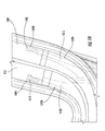
- Figure 4 illustrates an embodiment of the mouthpiece 220, referred to as a framed mouthpiece 400.
- An outer frame 410 of the framed mouthpiece 400 engages the handle 210.
- a snap hook 420 on the outer frame 410 attaches the outer frame 410 (and therefore the entire assembled mouthpiece 400) to the handle 210, engaging at least one eject button 230 on the handle 210.
- An inner frame 430 engages the outer frame 410, and sandwiches bristle strips (more fully described below and more fully illustrated in Figure 5 ) between the inner frame 430 and outer frame 410.
- the framed mouthpiece 400 is of a size and dimension so to fit in a user's mouth and allow bristle bundles 440 to engage substantially all the surfaces of substantially all the user's teeth.
- the outer frame 410 comprises an aperture 450 proximate the end of the outer frame that engages the handle 210.
- the aperture 450 provides a means for a drive system 540 to engage outer 500 and inner 510 bristle strips.
- Figure 5 more fully illustrates the embodiment of the framed mouthpiece 400 illustrated in Figure 4 .
- An outer bristle strip 500 engages the outer frame 410.
- An inner bristle strip 510 engages the inner frame 430.
- the inner frame 430 fixedly engages the outer frame 410, passing through an inner bristle strip aperture 520, and an outer bristle strip aperture 530, and flanks the inner bristle strip 510 and the outer bristle strip 500 between the inner frame 430 and the outer frame 410.
- a bristle strip assembly comprises the outer 500 and inner 510 bristle strips within a framed mouthpiece 400.
- Both the outer bristle strip 500 and the inner bristle strip 510 are of a substantially semi-elliptical shape adapted to follow the contours of a set of teeth.
- the bristle strips 500, 510 are made from at least one of high density polyethylene, low density polyethylene, polyethylene terephthalate, polyvinyl chloride, polypropylene, ABS, polyoxymethylene, polystyrene, post-consumer resin, K-resin, epoxy resin, phenolic formaldehyde resin, stainless steel, aluminium, titanium, ceramic, and any other material known in the art.
- the bristle strips 500, 510 are made of a thermoplastic elastomer.
- the substantially semi-elliptical inner bristle strip 510 nests substantially within the substantially semi-elliptical outer bristle strip 500, and forms at least one, and preferably two, substantially semi-elliptical channels of a suitable size and dimension to substantially envelope a set of teeth.
- an upper channel engages the upper teeth and a lower channel engages the lower teeth.
- the bristle strips 500, 510 comprise a plurality of bristle bundles 440 projecting from an inner surface of the channel.
- the bristle bundles 440 of the inner bristle strip 510 engage both the upper and lower lingual, occlusal, and incisal teeth surfaces.
- the bristle bundles 440 of the outer bristle strip 500 engage both the upper and lower facial, occlusal, and incisal teeth surfaces.
- the bristle bundles 440 of the bristle strips 500, 510 are designed to engage and clean all teeth surfaces simultaneously. Different sizes and shapes of the bristle strips 500, 510 are contemplated to accommodate a variety of mouth shapes and sizes. Offsetting the upper and lower channels can accommodate individuals with either an underbite or overbite.
- the inner 430 and outer 410 frames comprise edges that form a folded lip to protect a user's gums from getting caught between the bristle strip and the frame.
- the inner frame 410 engages the bristle strip 500 using a rail with the inner frame 410 and the outer frame 430 engages the bristle strip 510 using a rail on the outer frame 430.
- the rails provide guides upon which bristle strips 500, 510 can travel.
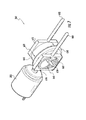
- Figures 6 , 7 and 8 illustrate, by way of example, an embodiment of a gear train 360.
- an armature 610 of the motor 350 fixedly engages a spur gear 620.
- the spur gear 620 engages a perpendicular face gear 630.
- the face gear 630 comprises a cylinder 640.
- the cylinder rotates along with the face gear 630 around an axle 650.
- Attached or moulded to the cylinder are two cams, a first cam 660 and a second cam 662, each cam 660, 662 being situated opposite to each other by approximately 180 ⁇ perpendicular the cylinder's 640 rotational axis.
- the cams 660, 662 are each offset from the cylinder 640, protruding outwardly from the interior of the cylinder 640 parallel to the rotational axis.
- the first cam 660 communicates with a first cam follower 670.
- the second cam 662 communicates with a second cam follower 672.
- the first cam follower 670 communicates with a first reciprocating pin 680, and the second cam follower 672 communicates with a second reciprocating pin 682.
- each cam follower 670, 672 is made of plastic, overmoulded onto each stainless steel reciprocating pin 680,682.
- the reciprocating pin 680,682 and cam follower 670, 672 are a single piece of moulded plastic.
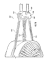
- Figure 9 illustrates, by way of example, an embodiment of a wire drive assembly 900 wherein a pulley 905 engages drive wires-an inner drive wire 910 and an outer drive wire 915.
- the pulley 905 reciprocates, and this reciprocating motion is communicated to the bristle strips 500, 510 via the drive wires 910, 915.
- a rocker linkage 920 pivotally communicates with the pulley 905.
- the pulley 905 is pivotally mounted to a central shaft 925.
- the central shaft 925 freely rotates around the central shaft's 925 long axis.
- the central shaft 925 communicates with at least one of a bushing and a bearing.
- the rocker linkage 920 engages a wrist pin 930 located peripherally on the pulley 905.
- the rocker linkage 920 engages the pulley 905 at a ball-and-socket joint.
- the rocker linkage 920 also communicates with a drive wheel 935.
- the rocker linkage 920 engages a second wrist pin 940 located peripherally on the drive wheel 935.
- the rocker linkage 920 engages the drive wheel 935 at a ball-and-socket joint.
- the drive wheel 935 rotates when the motor 350 is activated, causing the wrist pin 940 to rotate, which causes the rocker linkage 920, by virtue of being pivotally attached to the pulley 905, to force the pulley 905 to reciprocate about the central shaft 925.
- the pulley 905 comprises at least one externally grooved substantially circularly arched rail 1000 having a shape and dimension to engage the outer drive wire 915.
- the distal face of the rail 1005 comprises a groove 1005 traversing the length of the rail 1000.
- the groove 1005 captures the outer drive wire 915 under tension so that when the pulley 905 reciprocates, that reciprocating motion is transferred to the drive wire 915.
- the groove surface 1005 is textured to provide more friction to aid in gripping the drive wire 915 without slippage.
- the groove 1005 surface is ridged to provide more friction to aid in gripping the drive wire 915 without slippage.
- the groove surface 1005 is lined with a material, such as rubber, to provide more friction to aid in gripping the drive wire 915 without slippage.
- the pulley 905 comprises a circular boss 1010, the boss 1010 comprising a second groove 1015 that circumscribes the boss 1010.
- the second groove 1015 captures the inner drive wire 910 under tension so that when the pulley 905 reciprocates, that reciprocating motion is transferred to the inner drive wire 910.
- the second groove's 1015 surface is textured to provide more friction to aid in gripping the inner drive wire 910 without slippage.
- the second groove's 1015 surface is ridged to provide more friction to aid in gripping the inner drive wire 910 without slippage.
- the second groove's 1015 surface is lined with a material, such as rubber, to provide more friction to aid in gripping the inner drive wire 910 without slippage.
- the drive wires 915, 915 are made from at least one of metal, natural fibres, synthetic materials such as plastic monofilament, and any materials known in the art.
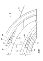
- Figure 11 further illustrates an embodiment of the wire drive system 900.
- the drive wires 910, 915 communicate with a bristle strip 500, 510 so to cause the bristle strips 500, 510 to reciprocate.
- the outer drive wire 915 terminates at opposed attachment points 1100 anchored in the outer bristle strip 500.
- the inner drive wire 910 terminates at opposed attachment points 1105 anchored in the inner bristle strip 510.
- the outer drive wire's 915 two attachment points 1100 alternately pull the opposing regions of the outer bristle strip 500 during every reciprocation of the pulley 905.
- the inner drive wire's 910 two attachment points 1105 alternately pull the opposing regions of the inner bristle strip 510 during every reciprocation of the pulley 905.
- the attachment points 1100, 1105 comprise a termination 1110, being at least one of spheres, crimps, tubes, hooks, and loops that are at least one of glued, crimped, tied, and welded to each drive wire 910, 915.
- the relatively large termination 1110 is trapped in a cavity 1115, 1117 of a suitable size and dimension to encase the termination 1110, so the termination 1110 is too large to pass through a channel 1120, 1122 in the bristle strip 500, 510, the channel 1120, 1122 however being large enough to accommodate a drive wire 910, 915.
- the inner drive wire 910 is crossed over itself so that each time the pulley pulls against the wires 910, 915, the wires pull on opposed termination points 1100, 1105 within the bristle strips 500, 510.
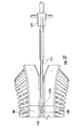
- Figure 12 illustrates, by way of example, an embodiment of a linkage drive assembly 1200 wherein a pivot bar 1205 engages a plurality of drive linkages, inner drive linkages 1210 and outer drive linkages 1215.
- the pivot bar 1205 reciprocates, and this reciprocating motion is communicated to the bristle strips 500, 510 via the drive linkages 1210, 1215.
- a rocker linkage 920 pivotally communicates with the pivot bar 1205.
- the pivot bar 1205 is pivotally mounted to a central shaft 1225.
- the central shaft 1225 freely rotates around the central shaft's 1225 long axis.
- the central shaft 1225 communicates with at least one of a bushing and a bearing.
- the rocker linkage 920 engages a wrist pin 1220 located peripherally on the pivot bar 1205.
- the rocker linkage 920 engages the pivot bar 1205 at a ball-and-socket joint.
- the rocker linkage 920 also communicates with a drive wheel 935.
- the rocker linkage 920 engages a second wrist pin 940 located peripherally on the drive wheel 935.
- the rocker linkage 920 engages the drive wheel 935 at a ball-and-socket joint.
- the drive wheel 935 rotates when the motor 350 is activated, which causes the rocker linkage 920, by virtue of being pivotally attached to the wrist pin 940, to force the pivot bar 1205 to reciprocate about the central shaft 1225.
- the pivot bar 1205 pivotally communicates with at least one ridged drive linkages 1210, 1215.
- the drive linkages 1210, 1215 communicate with wrist pins 1300 on the pivot bar 1205.
- the linkages 1210, 1215 each communicate with the pivot bar 1205 utilizing a ball-and-socket joint. The end of each linkage 1210, 1215 not in communication with the pivot bar 1205, engages the bristle strips 500, 510.
- the linkages 1210, 1215 are made from at least one of high density polyethylene, low density polyethylene, polyethylene terephthalate, polyvinyl chloride, polypropylene, polyoxymethylene, polystyrene, post-consumer resin, K-resin, epoxy resin, phenolic formaldehyde resin, stainless steel, aluminium, ceramic, and any other material known in the art.
- the pivot bar 1205 is made from made of at least one of high density polyethylene, low density polyethylene, polyethylene terephthalate, polyvinyl chloride, polypropylene, polyoxymethylene, polystyrene, post-consumer resin, K-resin, epoxy resin, phenolic formaldehyde resin, stainless steel, aluminium, ceramic, and any other material known in the art.
- the linkages 1210, 1215 may include ribs or indentations for strengthening purposes.
- Figure 13 illustrates an example of one embodiment of the drive assembly 500 wherein drive linkages 1210, 1215 pivotally communicate with the pivot bar 1205 by engaging a secondary plate 1305.
- the linkages are secured to wrist pins 1300.
- the wrist pins 1300 capture the pivot bar 1205 with barbed ends.
- the centre linkages 1210 comprise bends in the lengths of each drive linkage so that the inner drive linkages 1210 can cross paths to avoid mechanical interference.
- Figures 12 , 13 and 14 further illustrate an embodiment of the linkage drive system 900.
- the drive linkages 1210, 1215 communicate with a bristle strip 500, 510 so to cause the bristle strips 500, 510 to reciprocate.
- the outer drive linkage 1215 terminates at opposed attachment points 1400 anchored in the outer bristle strip 500.
- the inner drive linkage 1210 terminates at opposed attachment points 1405 anchored in the inner bristle strip 510.
- the outer drive linkage's 1215 two attachment points 1100 alternately reciprocate with the reciprocation of the pivot bar 1205.
- the inner drive linkage's 1210 two attachment points 1405 alternately reciprocate with the reciprocation of the pivot bar 1205.
- the attachment points 1400, 1405 each comprise a termination 1410, being at least one of barbs, cuboids, spheres, crimps, tubes, hooks, and loops that are at least one of glued, crimped, tied, moulded, and welded to each drive linkage 1210, 1215.
- the relatively large termination 1410 is trapped in the attachment points 1400, 1405 of a suitable size and dimension to encase the termination 1410, so the termination 1410 is too large to pass through a channel 1420, 1422 in the bristle strip 500, 510, the channel 1120, 1122 however being large enough to accommodate a drive linkage 1210, 1215.
- Figure 15 illustrates, by way of example, an alternative embodiment of a pin drive 1500.
- This embodiment of the drive system is actuated by the reciprocating motion of the first and second reciprocating pins 680, 682 of the gear train 360.
- the reciprocating pins 680, 682 alternately press against a pivot bar 1505, so that the pivot bar 1505 reciprocates on an axle 1507.
- the pivot bar 1505 pivotally communicates with at least one ridged drive linkages 1510, 1515.
- the drive linkages 1510, 1515 communicate with wrist pins 1520 on the pivot bar 1505.
- the drive linkages 1510, 1515 each communicate with the pivot bar 1505 utilizing a ball-and-socket joint.
- each linkage 1510, 1515 not in communication with the pivot bar 1505, engages the bristle strips 500, 510.
- the linkages 1510, 1515 are made from at least one of high density polyethylene, low density polyethylene, polyethylene terephthalate, polyvinyl chloride, polypropylene, polyoxymethylene, polystyrene, post-consumer resin, K-resin, epoxy resin, phenolic formaldehyde resin, stainless steel, aluminium, ceramic, and any other material known in the art.
- the pivot bar 1505 is made from made of at least one of high density polyethylene, low density polyethylene, polyethylene terephthalate, polyvinyl chloride, polypropylene, polyoxymethylene, polystyrene, post-consumer resin, K-resin, epoxy resin, phenolic formaldehyde resin, stainless steel, aluminium, ceramic, and any other material known in the art.
- the linkages 1210, 1215 may include ribs or indentations for strengthening purposes.
- Figure 16 illustrates an example of one embodiment of the pin drive assembly 1500 wherein drive linkages 1510, 1515 pivotally communicate with the pivot bar 1505 by engaging a secondary plate 1507.
- the drive linkages 1510, 1515 are secured to wrist pins 1520.
- the inner drive linkages 1510 comprise bends in the lengths of each drive linkage so that the inner drive linkages 1510 can cross paths to avoid mechanical interference.
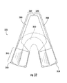
- Figures 15 , 16 and 17 further illustrate an embodiment of the linkage drive system 1500.
- the drive linkages 1510, 1515 each communicate with a bristle strip 500, 510 so to cause the bristle strips 500, 510 to reciprocate.
- the outer drive linkage 1515 terminates at opposed attachment points 1700 anchored in the outer bristle strip 500.
- the inner drive linkage 1510 terminates at opposed attachment points (not shown) anchored in the inner bristle strip 510.
- the outer drive linkage's 1515 two attachment points 1700 alternately reciprocate with the reciprocation of the pivot bar 1505.
- the inner drive linkage's 1510 two attachment points alternately reciprocate with the reciprocation of the pivot bar 1505.
- the attachment points 1700 each comprise a termination 1705, being at least one of barbs, cuboids, spheres, crimps, tubes, hooks, and loops that are at least one of glued, crimped, moulded, tied, and welded to each drive linkage 1510, 1515.
- the relatively large termination 1705 is trapped in the attachment points 1700 of a suitable size and dimension to encase the termination 1705, so each termination 1705 is too large to pass through a channel 1710 in each bristle strip 500, 510, the channel 1710 however being large enough to accommodate a drive linkage 1510, 1515.
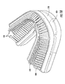
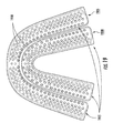
- Figure 18 illustrates an embodiment of inner and outer bristle strips 500, 510.
- the bristle strips 500, 510 comprise a plurality of bristle bundles 440, and engage the inner and outer frames 430, 410 of the mouthpiece assembly 400.
- the bristle strips 500, 510 are of a flexible or hinged type.
- the bristles bundles 440 of the inner bristle strip 510 engage both the upper and lower lingual, occlusal, and incisal teeth surfaces.
- the bristle bundles 440 of the outer bristle strip 500 engage both the upper and lower facial, occlusal, and incisal teeth surfaces.
- the bristle bundles 440 of the bristle strips 500, 510 are designed to engage and clean all teeth surfaces simultaneously. Different sizes and shapes of the bristle strips 500, 510 are contemplated to accommodate a variety of mouth shapes and sizes.
- the bristle strips 500, 510 embodiments herein described comprise a plurality of bristle bundles 440.
- the individual bristles of these bundles 440 are made from at least one of plastic, nylon, natural fibres (such as boar's hair or bamboo), thin metal (such as titanium), and any other material known in the art.
- the bristles are substantially evenly distributed on the bristle bearing surfaces of the bristle strips 500, 510.
- the bristles are organized into bristle bundles 440 of approximately 10 to 100 individual bristles. Bristle bundles 440 are available in a plurality of configurations.
- bristle bundles 440 are organized with bristles of varying lengths to form a pointed bristle bundle 440 (The longer bristles being in the centre of the bundle 440, progressively getting shorter as the radius of the bristle bundle 440 increases).
- the bristle bundle 440 is organized with bristles of varying lengths to form a cupped bristle bundle 440 (The shorter bristles being in the centre of the bundle 440, progressively getting longer as the radius of the bristle bundle 440 increases).
- Other variations include a chiselled bristle bundle 440 profile, and a flat bristle bundle 440 profile.
- differing bristle bundle configurations are distributed amongst different regions of the bristle strips 500, 510.
- Longer bristle bundles 440 are typically for the cleaning of the facial or lingual faces of teeth as well as the gum line.
- Shorter bristle bundles 440 typically clean the occlusal and incisal surfaces of teeth.
- Bristles are approximately perpendicular to the bristle strip, but the bristle strip itself comprises a multitude of contoured surfaces to allow the bristles to be angled in relation to the teeth.
- bristles shorten towards the molar-contacting end of the bristle strip to accommodate greater molar width. Bristles are fused or stapled to bristle strips 500, 510.
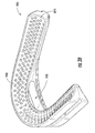
- Figures 19 and 20 illustrate an inner flexible bristle strip 1900 and an outer flexible bristle strip 1905.
- the bristle bundles 440 are not shown for the sake of clarity.
- the flexible bristle strips 1900, 1905 each have a middle flexible region 1910 and rigid end sections 1915.
- the bristle strips 1900, 1905 are substantially the same durometer throughout.
- the middle flexible regions 1910 communicate with approximately the incisor/cuspid/premolar regions of a user's mouth
- the rigid end sections 1915 communicate with the approximately the premolar/molar regions of a user's mouth.
- Figure 20 illustrates an aperture 1920 in the middle flexible region 1920 of the outer bristle strip 1905 for the purpose of allowing drive wires 910, 915 or linkages 1210, 1215, 1510, 1515 and inner 430 and outer frame 410 portions to pass.
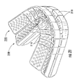
- Figures 21 and 22 illustrate, by way of example, one embodiment of a hinged inner bristle strip 2100 and a hinged outer bristle strip 2105.
- the bristle strips 2100, 2105 comprise a plurality of segments 2110, each segment 2110 capable of engaging a plurality of bristle bundles 440.
- the segments 2110 are hingedly linked to each other at individual hinges 2115.
- the bristle strips 2100, 2150 are of a unibody construction with a series of linked segments 2110 that each hingedly communicates with adjacent linked regions 2110 through living hinges.
- the hinges 2115 are situated at an edge of the bristle strips 2100, 2105.
- the edge can be either the inner edge as shown on the inner bristle strip 2100, or the outer edge as shown on the outer bristle strip 2105.
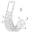
- the embodiment of Figure 23 illustrates the hinges 2115 situated in the middle of the segments 2110. Though these illustrations show middle or edge hinges 2115 on a particular bristle strip (either inner or outer) these hinge placements are equally applicable to the alternative bristle strip not specifically exemplified.
- the segments 2110 are each shaped to allow the necessary degree of hinged flexibility between the hinges 2115 so that the bristle strips 2100, 2105 can form a substantially semi-elliptical conformation.
- the bristle strips 2100, 2105 comprise regions of differing durometer.
- the segments 2110 of the bristle strips 2100, 2105 that communicate substantially with the incisor, cuspid, and premolar teeth are comprised of a flexible material, while the region of the bristle strips 2100, 2105 that communicate substantially with the molars are approximately rigid.
- the bristle strips 2100, 2105 are substantially the same durometer throughout.
- FIG 25 illustrates that instead of living hinges as hinges 2115 between segments 2110, as illustrated in Figure 25 , the hinges 2115 in an alternate embodiment are constructed from overmoulding.
- an overmoulded layer 2505 is bonded to a base material 2510, together forming the bristle strip 2500.
- the overmoulding 2505 is a flexible material so that the segments 2110 can hingedly move to allow the bristle strip 2500 to form substantially a U shape.
- Figure 26 illustrates the overmoulded bristle strip 2500 in a flat conformation. Due to the flexibility conferred upon the bristle strip 2500 due to the overmoulded layer 2505, the bristle strip 2500 can be flattened for manufacturing or assembly.
- the overmoulding 2505 runs substantially the entirety of the thickness of edge of the segments 2110. In an alternative embodiment, the overmoulding 2505 runs only a portion of the length of the thickness of edge of the segments 2110.
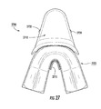
- Figures 27-30 illustrate an embodiment of a non-framed rigid beam mouthpiece 2700.
- a bristle strip assembly 2705 engages an outer guard 2710, and is secured in place by an inner guard 2715 that engages the outer guard 2710 through the bristle strip assembly 2705.
- the inner guard 2715 is welded to the outer guard 2710.
- the outer guard 2710 comprises snap hooks 2720 for securing the mouthpiece to a handle 210.
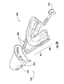
- Figure 28 also illustrates the assembly described above and illustrated in Figure 27 .
- FIGs 28 and 29 illustrate, among other things, the rigid beams 2800 of the bristle strip assembly 2705.
- the rigid beams 2800 promote structural integrity of the bristle strip assembly 2705. They also provide the means for the bristle strips to communicate with the gear train 700 so that the reciprocating motion of the reciprocating pins 780, 782 is conferred to the bristle strips.
- the rigid beams 2800 are made of at least one of high density polyethylene, low density polyethylene, polyethylene terephthalate, polyvinyl chloride, polypropylene, polyoxymethylene, polystyrene, post-consumer resin, K-resin, epoxy resin, phenolic formaldehyde resin, stainless steel, aluminium, ceramic, and any other material known in the art.
- the rigid beams 2800 are made from a substantially non-reactive substance such as stainless steel.
- the bristle strip assembly 2705 can comprise regions of varying durometer.
- the flexible region 2810 that communicates substantially with the incisor, cuspid, and premolar teeth is comprised of a flexible material, while the rigid regions 2885 of the bristle strip assembly 2705 that communicate substantially with the molars are approximately rigid.
- the flexible region 2810 allows the bristle strip to move around the curve of the dental arch due to the flexible region's 2810 compliance.
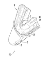
- FIGs 27-30 illustrate an embodiment of a non-framed rigid beam mouthpiece 2700 utilizing an H-beam construction.
- the substantially rigid H-beam 2800 fixedly engages the upper bristle strip 3100 and lower bristle strip 3105.
- the H-beam 2800 engages proximate the molar-contacting region at the rigid region of the bristle strips 2815.
- the rigid region 2815 is over moulded over the rigid H-beam 2800.
- the H-beam 2800 tapers and projects outwardly from the rigid region 2815 as a relatively thin projection that terminates by turning inwardly forming a foot 3200.
- the foot 3200 engages the reciprocating pins 780, 782 of the gear train 700 that alternately press against the feet 3200 to confer motion to the bristle strips 3100, 3105.
- a solid flexible region 2810 of the bristle strips 3100, 3105 is substituted with a segmented region 3400.
- the segmented region 3400 is constructed of a flexible or rigid material.
- the segmented region 3400 is of a unibody construction with a series of linked segments that each hingedly communicate with adjacent segments through hinges 3405, which are preferably living hinges.
- hinges 3405 are constructed from overmoulding.
- the overmoulding is a flexible material so that the segmented region 3400 can hingedly move to allow the bristle strips 3100, 3105 to form substantially a U-shape and to reciprocate under actuation.
- the segmented region 3400 is constructed from a flexible material that is compliant enough to allow motion of the bristle strip 3100, 3105.
- the hinges 3405 are separate bowtie-like shaped pieces of material that slidingly engage dovetail-shaped slots in each segment of the segmented region 3400.
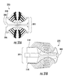
- FIGS 35a and 35b illustrate an embodiment of a rigid beam mouthpiece utilizing an I-beam construction 3500.
- a substantially rigid I-beam 3505 communicates with an upper t-slot 3510 in the upper bristle strip 3515 and a lower t-slot 3520 in the lower bristle strip 3525.
- the I-beam 3505 is made of at least one of high density polyethylene, low density polyethylene, polyethylene terephthalate, polyvinyl chloride, polypropylene, polyoxymethylene, polystyrene, post-consumer resin, K-resin, epoxy resin, phenolic formaldehyde resin, stainless steel, aluminium, ceramic, and any other material known in the art.
- the I-beam 3505 is made from a substantially non-reactive substance such as stainless steel.
- the I-beam 3505 engages the bristle strips 3510, 3515 tightly so that minimal movement between the bristle strips 3510, 3515 and the I-beam 3505 occurs.
- the I-beam 3505 engages the bristle strips 3510, 3515 loosely so that the bristle strips 3510, 3515 slidingly engage the I-beam 3505.
- Figures 36a and 36b illustrate an embodiment of an I-beam construction wherein a unibody bristle strip section 3600 is of a unibody construction and the I-beam 3505 is embedded within the bristle strip 3600.
- This construction allows a thinner mouthpiece to be made, for the I-beam take less space than an H-beam.
- the invention contemplates a method for brushing all of a subject's teeth simultaneously.
- a user would typically first charge the power supply of a rechargeable toothbrush 100 by placing the toothbrush in a charging base 225.
- the base 225 capable of accepting alternating current electricity and recharging a direct current power source such as a battery 340 through a wireless electrical induction circuit, or through direct circuit contact utilizing electrodes in the base 225.
- a user of the toothbrush 100 attaches the mouthpiece 220 to the handle 210.
- the mouthpiece comprises any of the bristle strip embodiments disclosed herein.
- the mouthpiece 220 comprises bristle strips capable of engaging all of a user's teeth simultaneously and the handle 210 comprises the battery 340 that powers a motor 350 that actuates any of the drive mechanisms 900, 1200, 1500 or the gear train 700 disclosed herein.
- the drive mechanisms 900, 1200, 1500 or the gear train 700 engage the bristle strips, causing a reciprocating motion of the bristle strips.
- the user actuates a power control 390, typically a button or a switch, on the handle 210 of the toothbrush 100 to provide power to the motor 350 to drive the drive mechanisms 900, 1200, 1500 or the gear train 700.
- a power control 390 typically a button or a switch
- the user places the mouthpiece 220 in the user's mouth so that the bristle strips engage all surfaces of all the user's teeth simultaneously. This may be accompanied by the use of toothpaste, baking soda, or mouthwash applied to the bristle strips.
- the user maintains contact between the user's teeth and the reciprocating bristles to clean the user's teeth, brushing all of a user's teeth simultaneously.
- the user actuates a power control 390 before or after placing the mouthpiece 220 in their mouth.
- the user When the user is finished brushing their teeth, the user removes the mouthpiece 220 from their mouth and turns off the toothbrush by actuating a power control 390 to remove power from the motor 350.
- control circuitry automatically turns off the motor 350 after an appropriate amount of time has passed.
Landscapes
- Health & Medical Sciences (AREA)
- Dentistry (AREA)
- Epidemiology (AREA)
- Life Sciences & Earth Sciences (AREA)
- Animal Behavior & Ethology (AREA)
- General Health & Medical Sciences (AREA)
- Public Health (AREA)
- Veterinary Medicine (AREA)
- Brushes (AREA)
Applications Claiming Priority (2)
| Application Number | Priority Date | Filing Date | Title |
|---|---|---|---|
| US13/182,414 US8635731B2 (en) | 2011-07-13 | 2011-07-13 | Teethbrush |
| US13/486,135 US8631531B2 (en) | 2011-07-13 | 2012-06-01 | Apparatus and method for brushing teeth |
Publications (3)
| Publication Number | Publication Date |
|---|---|
| EP2545883A2 true EP2545883A2 (de) | 2013-01-16 |
| EP2545883A3 EP2545883A3 (de) | 2016-11-02 |
| EP2545883B1 EP2545883B1 (de) | 2022-11-16 |
Family
ID=46581767
Family Applications (1)
| Application Number | Title | Priority Date | Filing Date |
|---|---|---|---|
| EP12176303.1A Active EP2545883B1 (de) | 2011-07-13 | 2012-07-13 | Vorrichtung zum Bürsten der Zähne |
Country Status (2)
| Country | Link |
|---|---|
| US (1) | US8631531B2 (de) |
| EP (1) | EP2545883B1 (de) |
Cited By (5)
| Publication number | Priority date | Publication date | Assignee | Title |
|---|---|---|---|---|
| FR3041244A1 (fr) * | 2015-09-21 | 2017-03-24 | Marc Gadille | Brosse a dents electrique 4 en1, 1 pour 4 |
| WO2019109486A1 (zh) * | 2017-12-05 | 2019-06-13 | 深圳苏琪科技有限公司 | 全自动智能牙刷 |
| CN111265323A (zh) * | 2020-04-03 | 2020-06-12 | 河南科技大学 | 一种基于巴氏法的智能刷牙机器人 |
| US20230145447A1 (en) * | 2020-04-15 | 2023-05-11 | Koninklijke Philips N.V. | Mouthpiece for a dental cleaning system and the dental cleaning system |
| EP4302725A1 (de) * | 2022-07-04 | 2024-01-10 | Koninklijke Philips N.V. | Reinigungsabschnitt für eine mundreinigungsvorrichtung |
Families Citing this family (21)
| Publication number | Priority date | Publication date | Assignee | Title |
|---|---|---|---|---|
| US20150250571A1 (en) * | 2014-03-04 | 2015-09-10 | Dan Oelgiesser | Dental Device |
| US8978189B1 (en) * | 2014-07-11 | 2015-03-17 | Curtis Bernard Sexton | Omnibrush |
| US12053339B2 (en) * | 2014-11-11 | 2024-08-06 | ZeroBrush Inc. | Methods of designing and fabricating customized dental care for particular users |
| US10888201B2 (en) | 2014-11-11 | 2021-01-12 | ZeroBrush, Inc. | Systems, devices, and methods for providing customized oral care agents |
| US12337544B2 (en) | 2014-11-11 | 2025-06-24 | ZeroBrush, Inc. | Methods of designing and fabricating customized dental care for particular users |
| US11058523B2 (en) * | 2014-11-11 | 2021-07-13 | ZeroBrush, Inc. | Methods of designing and fabricating customized dental care for particular users |
| US11213118B2 (en) * | 2014-11-11 | 2022-01-04 | ZeroBrush, Inc. | Methods and devices for personalized dental care |
| US10869541B2 (en) | 2014-11-11 | 2020-12-22 | ZeroBrush, Inc. | Systems, devices, and methods for customized dental care |
| US20150282910A1 (en) * | 2015-06-17 | 2015-10-08 | Dr. Elena G. Furdui-Carr | Oral hygiene device |
| US10314679B2 (en) | 2015-07-09 | 2019-06-11 | Andrew BLANK | Hands-free oral care device and method |
| USD781427S1 (en) | 2015-07-09 | 2017-03-14 | Andrew BLANK | Hands-free oral care device |
| USD785803S1 (en) * | 2015-07-15 | 2017-05-02 | David Penn Consulting Pty Limited | Dental appliance |
| US11246400B2 (en) | 2018-11-05 | 2022-02-15 | Alke, Llc | Automatic toothbrushes |
| IT201900003441A1 (it) * | 2019-03-08 | 2020-09-08 | Advanced Brush | Dispositivo perfezionato per l’igiene dentale |
| USD890350S1 (en) | 2020-01-07 | 2020-07-14 | ZeroBrush, Inc. | Teeth cleaning system |
| CN112294479B (zh) * | 2020-07-08 | 2022-07-15 | 东莞市均谊视觉科技有限公司 | 一种机械联动式洁牙器 |
| WO2022224033A1 (en) * | 2021-04-24 | 2022-10-27 | Hajian Nima | Full mouth toothbrush |
| CN113229977B (zh) * | 2021-06-29 | 2022-09-16 | 丽水市日峰电器有限公司 | 电动牙刷 |
| CN113892751B (zh) * | 2021-10-13 | 2023-05-12 | 深圳市盈泰塑胶电子科技有限公司 | 一种新型牙刷头及往复式驱动的口腔护理器 |
| CN114376754B (zh) * | 2021-12-16 | 2022-11-01 | 杭州电子科技大学技术转移有限公司 | 一种适用于幼儿的电动牙刷 |
| WO2025085917A1 (en) * | 2023-10-20 | 2025-04-24 | ZeroBrush, Inc. | Customized mouthpiece and drive mechanism coupled via multiple connection points |
Family Cites Families (4)
| Publication number | Priority date | Publication date | Assignee | Title |
|---|---|---|---|---|
| JPH04208105A (ja) * | 1990-11-30 | 1992-07-29 | Sachiko Muratsu | 歯磨装置 |
| US5177827A (en) * | 1991-01-14 | 1993-01-12 | Ellison Benedict M | Electric-powered dental brush |
| KR100397187B1 (ko) * | 2000-12-12 | 2003-09-06 | 고경용 | 전동 칫솔 |
| US7059853B2 (en) * | 2002-06-03 | 2006-06-13 | Cra Labs, Inc. | Oral irrigation and/or brushing devices and/or methods |
-
2012
- 2012-06-01 US US13/486,135 patent/US8631531B2/en active Active
- 2012-07-13 EP EP12176303.1A patent/EP2545883B1/de active Active
Non-Patent Citations (1)
| Title |
|---|
| None |
Cited By (7)
| Publication number | Priority date | Publication date | Assignee | Title |
|---|---|---|---|---|
| FR3041244A1 (fr) * | 2015-09-21 | 2017-03-24 | Marc Gadille | Brosse a dents electrique 4 en1, 1 pour 4 |
| WO2019109486A1 (zh) * | 2017-12-05 | 2019-06-13 | 深圳苏琪科技有限公司 | 全自动智能牙刷 |
| CN111265323A (zh) * | 2020-04-03 | 2020-06-12 | 河南科技大学 | 一种基于巴氏法的智能刷牙机器人 |
| US20230145447A1 (en) * | 2020-04-15 | 2023-05-11 | Koninklijke Philips N.V. | Mouthpiece for a dental cleaning system and the dental cleaning system |
| US12427006B2 (en) * | 2020-04-15 | 2025-09-30 | Koninklijke Philips N.V. | Mouthpiece for a dental cleaning system and the dental cleaning system |
| EP4302725A1 (de) * | 2022-07-04 | 2024-01-10 | Koninklijke Philips N.V. | Reinigungsabschnitt für eine mundreinigungsvorrichtung |
| WO2024008458A1 (en) * | 2022-07-04 | 2024-01-11 | Koninklijke Philips N.V. | Cleaning section for an oral cleaning device |
Also Published As
| Publication number | Publication date |
|---|---|
| US20130014332A1 (en) | 2013-01-17 |
| US8631531B2 (en) | 2014-01-21 |
| EP2545883A3 (de) | 2016-11-02 |
| EP2545883B1 (de) | 2022-11-16 |
Similar Documents
| Publication | Publication Date | Title |
|---|---|---|
| US8631531B2 (en) | Apparatus and method for brushing teeth | |
| US8635731B2 (en) | Teethbrush | |
| US5148567A (en) | Toothbrush | |
| US5027463A (en) | Toothbrush | |
| TWI344345B (en) | Toothbrush with enhanced cleaning effects | |
| US20090229062A1 (en) | Dental hygiene device | |
| US12023212B2 (en) | Dental cleaning device | |
| US20080052845A1 (en) | Cylindrical dual rotating electric toothbrush | |
| KR101346040B1 (ko) | 칫솔 | |
| MXPA04012317A (es) | Cepillos dentales electricos modulares remision a una solicitud relacionada. | |
| KR101412007B1 (ko) | 회전형 전동 칫솔 | |
| US20130000668A1 (en) | Dental interproximal cleaning device | |
| US8505557B1 (en) | Powered dental cleaner | |
| US20120174938A1 (en) | Rotating toothbrush | |
| JP2023504313A (ja) | 歯のクリーニングシステム及び使用方法 | |
| US20110136081A1 (en) | Gum saver toothbrush system | |
| DK1926409T3 (en) | TOOTHBRUSH | |
| US8584292B1 (en) | Dual rotating electric toothbrush | |
| RU2329009C2 (ru) | Зубная щетка с приводом и с уникальной рукояткой | |
| KR102495925B1 (ko) | 반려동물용 전동 칫솔 | |
| US20240065430A1 (en) | Interproximal brush floss pick | |
| CN200973759Y (zh) | 口腔清洁用品 | |
| CN211703785U (zh) | 一种u型手动牙刷 | |
| JP4198740B1 (ja) | 歯ブラシ | |
| WO2025021601A1 (en) | One-size-fits-all personal care device comprising auxetic components |
Legal Events
| Date | Code | Title | Description |
|---|---|---|---|
| PUAI | Public reference made under article 153(3) epc to a published international application that has entered the european phase |
Free format text: ORIGINAL CODE: 0009012 |
|
| AK | Designated contracting states |
Kind code of ref document: A2 Designated state(s): AL AT BE BG CH CY CZ DE DK EE ES FI FR GB GR HR HU IE IS IT LI LT LU LV MC MK MT NL NO PL PT RO RS SE SI SK SM TR |
|
| AX | Request for extension of the european patent |
Extension state: BA ME |
|
| PUAL | Search report despatched |
Free format text: ORIGINAL CODE: 0009013 |
|
| AK | Designated contracting states |
Kind code of ref document: A3 Designated state(s): AL AT BE BG CH CY CZ DE DK EE ES FI FR GB GR HR HU IE IS IT LI LT LU LV MC MK MT NL NO PL PT RO RS SE SI SK SM TR |
|
| AX | Request for extension of the european patent |
Extension state: BA ME |
|
| RIC1 | Information provided on ipc code assigned before grant |
Ipc: A61C 17/22 20060101AFI20160927BHEP |
|
| STAA | Information on the status of an ep patent application or granted ep patent |
Free format text: STATUS: REQUEST FOR EXAMINATION WAS MADE |
|
| 17P | Request for examination filed |
Effective date: 20170419 |
|
| RBV | Designated contracting states (corrected) |
Designated state(s): AL AT BE BG CH CY CZ DE DK EE ES FI FR GB GR HR HU IE IS IT LI LT LU LV MC MK MT NL NO PL PT RO RS SE SI SK SM TR |
|
| STAA | Information on the status of an ep patent application or granted ep patent |
Free format text: STATUS: EXAMINATION IS IN PROGRESS |
|
| 17Q | First examination report despatched |
Effective date: 20200515 |
|
| GRAP | Despatch of communication of intention to grant a patent |
Free format text: ORIGINAL CODE: EPIDOSNIGR1 |
|
| STAA | Information on the status of an ep patent application or granted ep patent |
Free format text: STATUS: GRANT OF PATENT IS INTENDED |
|
| INTG | Intention to grant announced |
Effective date: 20220531 |
|
| RIN1 | Information on inventor provided before grant (corrected) |
Inventor name: BREWSTER, JAMES Inventor name: HORNSTEIN, ALEXIS Inventor name: SHARPE, NATHANIEL Inventor name: BRUNDAGE, HEATHER Inventor name: GARNER, ROBERT |
|
| GRAS | Grant fee paid |
Free format text: ORIGINAL CODE: EPIDOSNIGR3 |
|
| GRAA | (expected) grant |
Free format text: ORIGINAL CODE: 0009210 |
|
| STAA | Information on the status of an ep patent application or granted ep patent |
Free format text: STATUS: THE PATENT HAS BEEN GRANTED |
|
| AK | Designated contracting states |
Kind code of ref document: B1 Designated state(s): AL AT BE BG CH CY CZ DE DK EE ES FI FR GB GR HR HU IE IS IT LI LT LU LV MC MK MT NL NO PL PT RO RS SE SI SK SM TR |
|
| REG | Reference to a national code |
Ref country code: GB Ref legal event code: FG4D |
|
| REG | Reference to a national code |
Ref country code: CH Ref legal event code: EP |
|
| REG | Reference to a national code |
Ref country code: DE Ref legal event code: R096 Ref document number: 602012079004 Country of ref document: DE |
|
| REG | Reference to a national code |
Ref country code: IE Ref legal event code: FG4D |
|
| REG | Reference to a national code |
Ref country code: AT Ref legal event code: REF Ref document number: 1531305 Country of ref document: AT Kind code of ref document: T Effective date: 20221215 |
|
| REG | Reference to a national code |
Ref country code: NL Ref legal event code: FP |
|
| REG | Reference to a national code |
Ref country code: LT Ref legal event code: MG9D |
|
| REG | Reference to a national code |
Ref country code: AT Ref legal event code: MK05 Ref document number: 1531305 Country of ref document: AT Kind code of ref document: T Effective date: 20221116 |
|
| PG25 | Lapsed in a contracting state [announced via postgrant information from national office to epo] |
Ref country code: SE Free format text: LAPSE BECAUSE OF FAILURE TO SUBMIT A TRANSLATION OF THE DESCRIPTION OR TO PAY THE FEE WITHIN THE PRESCRIBED TIME-LIMIT Effective date: 20221116 Ref country code: PT Free format text: LAPSE BECAUSE OF FAILURE TO SUBMIT A TRANSLATION OF THE DESCRIPTION OR TO PAY THE FEE WITHIN THE PRESCRIBED TIME-LIMIT Effective date: 20230316 Ref country code: NO Free format text: LAPSE BECAUSE OF FAILURE TO SUBMIT A TRANSLATION OF THE DESCRIPTION OR TO PAY THE FEE WITHIN THE PRESCRIBED TIME-LIMIT Effective date: 20230216 Ref country code: LT Free format text: LAPSE BECAUSE OF FAILURE TO SUBMIT A TRANSLATION OF THE DESCRIPTION OR TO PAY THE FEE WITHIN THE PRESCRIBED TIME-LIMIT Effective date: 20221116 Ref country code: FI Free format text: LAPSE BECAUSE OF FAILURE TO SUBMIT A TRANSLATION OF THE DESCRIPTION OR TO PAY THE FEE WITHIN THE PRESCRIBED TIME-LIMIT Effective date: 20221116 Ref country code: ES Free format text: LAPSE BECAUSE OF FAILURE TO SUBMIT A TRANSLATION OF THE DESCRIPTION OR TO PAY THE FEE WITHIN THE PRESCRIBED TIME-LIMIT Effective date: 20221116 Ref country code: AT Free format text: LAPSE BECAUSE OF FAILURE TO SUBMIT A TRANSLATION OF THE DESCRIPTION OR TO PAY THE FEE WITHIN THE PRESCRIBED TIME-LIMIT Effective date: 20221116 |
|
| PG25 | Lapsed in a contracting state [announced via postgrant information from national office to epo] |
Ref country code: RS Free format text: LAPSE BECAUSE OF FAILURE TO SUBMIT A TRANSLATION OF THE DESCRIPTION OR TO PAY THE FEE WITHIN THE PRESCRIBED TIME-LIMIT Effective date: 20221116 Ref country code: PL Free format text: LAPSE BECAUSE OF FAILURE TO SUBMIT A TRANSLATION OF THE DESCRIPTION OR TO PAY THE FEE WITHIN THE PRESCRIBED TIME-LIMIT Effective date: 20221116 Ref country code: LV Free format text: LAPSE BECAUSE OF FAILURE TO SUBMIT A TRANSLATION OF THE DESCRIPTION OR TO PAY THE FEE WITHIN THE PRESCRIBED TIME-LIMIT Effective date: 20221116 Ref country code: IS Free format text: LAPSE BECAUSE OF FAILURE TO SUBMIT A TRANSLATION OF THE DESCRIPTION OR TO PAY THE FEE WITHIN THE PRESCRIBED TIME-LIMIT Effective date: 20230316 Ref country code: HR Free format text: LAPSE BECAUSE OF FAILURE TO SUBMIT A TRANSLATION OF THE DESCRIPTION OR TO PAY THE FEE WITHIN THE PRESCRIBED TIME-LIMIT Effective date: 20221116 Ref country code: GR Free format text: LAPSE BECAUSE OF FAILURE TO SUBMIT A TRANSLATION OF THE DESCRIPTION OR TO PAY THE FEE WITHIN THE PRESCRIBED TIME-LIMIT Effective date: 20230217 |
|
| PG25 | Lapsed in a contracting state [announced via postgrant information from national office to epo] |
Ref country code: SM Free format text: LAPSE BECAUSE OF FAILURE TO SUBMIT A TRANSLATION OF THE DESCRIPTION OR TO PAY THE FEE WITHIN THE PRESCRIBED TIME-LIMIT Effective date: 20221116 Ref country code: RO Free format text: LAPSE BECAUSE OF FAILURE TO SUBMIT A TRANSLATION OF THE DESCRIPTION OR TO PAY THE FEE WITHIN THE PRESCRIBED TIME-LIMIT Effective date: 20221116 Ref country code: EE Free format text: LAPSE BECAUSE OF FAILURE TO SUBMIT A TRANSLATION OF THE DESCRIPTION OR TO PAY THE FEE WITHIN THE PRESCRIBED TIME-LIMIT Effective date: 20221116 Ref country code: DK Free format text: LAPSE BECAUSE OF FAILURE TO SUBMIT A TRANSLATION OF THE DESCRIPTION OR TO PAY THE FEE WITHIN THE PRESCRIBED TIME-LIMIT Effective date: 20221116 Ref country code: CZ Free format text: LAPSE BECAUSE OF FAILURE TO SUBMIT A TRANSLATION OF THE DESCRIPTION OR TO PAY THE FEE WITHIN THE PRESCRIBED TIME-LIMIT Effective date: 20221116 |
|
| REG | Reference to a national code |
Ref country code: DE Ref legal event code: R097 Ref document number: 602012079004 Country of ref document: DE |
|
| PG25 | Lapsed in a contracting state [announced via postgrant information from national office to epo] |
Ref country code: SK Free format text: LAPSE BECAUSE OF FAILURE TO SUBMIT A TRANSLATION OF THE DESCRIPTION OR TO PAY THE FEE WITHIN THE PRESCRIBED TIME-LIMIT Effective date: 20221116 Ref country code: AL Free format text: LAPSE BECAUSE OF FAILURE TO SUBMIT A TRANSLATION OF THE DESCRIPTION OR TO PAY THE FEE WITHIN THE PRESCRIBED TIME-LIMIT Effective date: 20221116 |
|
| PLBE | No opposition filed within time limit |
Free format text: ORIGINAL CODE: 0009261 |
|
| STAA | Information on the status of an ep patent application or granted ep patent |
Free format text: STATUS: NO OPPOSITION FILED WITHIN TIME LIMIT |
|
| 26N | No opposition filed |
Effective date: 20230817 |
|
| PG25 | Lapsed in a contracting state [announced via postgrant information from national office to epo] |
Ref country code: SI Free format text: LAPSE BECAUSE OF FAILURE TO SUBMIT A TRANSLATION OF THE DESCRIPTION OR TO PAY THE FEE WITHIN THE PRESCRIBED TIME-LIMIT Effective date: 20221116 |
|
| PG25 | Lapsed in a contracting state [announced via postgrant information from national office to epo] |
Ref country code: IT Free format text: LAPSE BECAUSE OF FAILURE TO SUBMIT A TRANSLATION OF THE DESCRIPTION OR TO PAY THE FEE WITHIN THE PRESCRIBED TIME-LIMIT Effective date: 20221116 |
|
| PG25 | Lapsed in a contracting state [announced via postgrant information from national office to epo] |
Ref country code: BG Free format text: LAPSE BECAUSE OF FAILURE TO SUBMIT A TRANSLATION OF THE DESCRIPTION OR TO PAY THE FEE WITHIN THE PRESCRIBED TIME-LIMIT Effective date: 20221116 |
|
| PG25 | Lapsed in a contracting state [announced via postgrant information from national office to epo] |
Ref country code: BG Free format text: LAPSE BECAUSE OF FAILURE TO SUBMIT A TRANSLATION OF THE DESCRIPTION OR TO PAY THE FEE WITHIN THE PRESCRIBED TIME-LIMIT Effective date: 20221116 |
|
| PG25 | Lapsed in a contracting state [announced via postgrant information from national office to epo] |
Ref country code: CY Free format text: LAPSE BECAUSE OF FAILURE TO SUBMIT A TRANSLATION OF THE DESCRIPTION OR TO PAY THE FEE WITHIN THE PRESCRIBED TIME-LIMIT; INVALID AB INITIO Effective date: 20120713 |
|
| PG25 | Lapsed in a contracting state [announced via postgrant information from national office to epo] |
Ref country code: HU Free format text: LAPSE BECAUSE OF FAILURE TO SUBMIT A TRANSLATION OF THE DESCRIPTION OR TO PAY THE FEE WITHIN THE PRESCRIBED TIME-LIMIT; INVALID AB INITIO Effective date: 20120713 |
|
| PGFP | Annual fee paid to national office [announced via postgrant information from national office to epo] |
Ref country code: NL Payment date: 20250716 Year of fee payment: 14 Ref country code: LU Payment date: 20250716 Year of fee payment: 14 |
|
| PGFP | Annual fee paid to national office [announced via postgrant information from national office to epo] |
Ref country code: DE Payment date: 20250722 Year of fee payment: 14 |
|
| PGFP | Annual fee paid to national office [announced via postgrant information from national office to epo] |
Ref country code: MC Payment date: 20250723 Year of fee payment: 14 |
|
| PGFP | Annual fee paid to national office [announced via postgrant information from national office to epo] |
Ref country code: BE Payment date: 20250716 Year of fee payment: 14 Ref country code: GB Payment date: 20250710 Year of fee payment: 14 |
|
| PGFP | Annual fee paid to national office [announced via postgrant information from national office to epo] |
Ref country code: FR Payment date: 20250711 Year of fee payment: 14 |
|
| PGFP | Annual fee paid to national office [announced via postgrant information from national office to epo] |
Ref country code: CH Payment date: 20250808 Year of fee payment: 14 |
|
| PGFP | Annual fee paid to national office [announced via postgrant information from national office to epo] |
Ref country code: IE Payment date: 20250716 Year of fee payment: 14 |