EP2544968B1 - Bin for collecting solid waste - Google Patents
Bin for collecting solid waste Download PDFInfo
- Publication number
- EP2544968B1 EP2544968B1 EP11713979.0A EP11713979A EP2544968B1 EP 2544968 B1 EP2544968 B1 EP 2544968B1 EP 11713979 A EP11713979 A EP 11713979A EP 2544968 B1 EP2544968 B1 EP 2544968B1
- Authority
- EP
- European Patent Office
- Prior art keywords
- bin
- lid
- locking
- housing
- waste
- Prior art date
- Legal status (The legal status is an assumption and is not a legal conclusion. Google has not performed a legal analysis and makes no representation as to the accuracy of the status listed.)
- Active
Links
Images


Classifications
-
- B—PERFORMING OPERATIONS; TRANSPORTING
- B65—CONVEYING; PACKING; STORING; HANDLING THIN OR FILAMENTARY MATERIAL
- B65D—CONTAINERS FOR STORAGE OR TRANSPORT OF ARTICLES OR MATERIALS, e.g. BAGS, BARRELS, BOTTLES, BOXES, CANS, CARTONS, CRATES, DRUMS, JARS, TANKS, HOPPERS, FORWARDING CONTAINERS; ACCESSORIES, CLOSURES, OR FITTINGS THEREFOR; PACKAGING ELEMENTS; PACKAGES
- B65D21/00—Nestable, stackable or joinable containers; Containers of variable capacity
- B65D21/02—Containers specially shaped, or provided with fittings or attachments, to facilitate nesting, stacking, or joining together
-
- B—PERFORMING OPERATIONS; TRANSPORTING
- B65—CONVEYING; PACKING; STORING; HANDLING THIN OR FILAMENTARY MATERIAL
- B65F—GATHERING OR REMOVAL OF DOMESTIC OR LIKE REFUSE
- B65F1/00—Refuse receptacles; Accessories therefor
- B65F1/14—Other constructional features; Accessories
- B65F1/16—Lids or covers
- B65F1/1607—Lids or covers with filling openings
-
- B—PERFORMING OPERATIONS; TRANSPORTING
- B65—CONVEYING; PACKING; STORING; HANDLING THIN OR FILAMENTARY MATERIAL
- B65F—GATHERING OR REMOVAL OF DOMESTIC OR LIKE REFUSE
- B65F1/00—Refuse receptacles; Accessories therefor
- B65F1/14—Other constructional features; Accessories
- B65F1/1468—Means for facilitating the transport of the receptacle, e.g. wheels, rolls
- B65F1/1473—Receptacles having wheels
-
- B—PERFORMING OPERATIONS; TRANSPORTING
- B65—CONVEYING; PACKING; STORING; HANDLING THIN OR FILAMENTARY MATERIAL
- B65F—GATHERING OR REMOVAL OF DOMESTIC OR LIKE REFUSE
- B65F1/00—Refuse receptacles; Accessories therefor
- B65F1/14—Other constructional features; Accessories
- B65F1/16—Lids or covers
- B65F1/1615—Lids or covers with means for locking, fastening or permanently closing thereof
-
- B—PERFORMING OPERATIONS; TRANSPORTING
- B65—CONVEYING; PACKING; STORING; HANDLING THIN OR FILAMENTARY MATERIAL
- B65F—GATHERING OR REMOVAL OF DOMESTIC OR LIKE REFUSE
- B65F2210/00—Equipment of refuse receptacles
- B65F2210/108—Authorization means
-
- B—PERFORMING OPERATIONS; TRANSPORTING
- B65—CONVEYING; PACKING; STORING; HANDLING THIN OR FILAMENTARY MATERIAL
- B65F—GATHERING OR REMOVAL OF DOMESTIC OR LIKE REFUSE
- B65F2210/00—Equipment of refuse receptacles
- B65F2210/172—Solar cells
-
- B—PERFORMING OPERATIONS; TRANSPORTING
- B65—CONVEYING; PACKING; STORING; HANDLING THIN OR FILAMENTARY MATERIAL
- B65F—GATHERING OR REMOVAL OF DOMESTIC OR LIKE REFUSE
- B65F2210/00—Equipment of refuse receptacles
- B65F2210/184—Weighing means
-
- G—PHYSICS
- G01—MEASURING; TESTING
- G01G—WEIGHING
- G01G3/00—Weighing apparatus characterised by the use of elastically-deformable members, e.g. spring balances
-
- G—PHYSICS
- G01—MEASURING; TESTING
- G01G—WEIGHING
- G01G3/00—Weighing apparatus characterised by the use of elastically-deformable members, e.g. spring balances
- G01G3/02—Weighing apparatus characterised by the use of elastically-deformable members, e.g. spring balances wherein the weighing element is in the form of a helical spring
- G01G3/04—Weighing apparatus characterised by the use of elastically-deformable members, e.g. spring balances wherein the weighing element is in the form of a helical spring using a plurality of springs
-
- G—PHYSICS
- G01—MEASURING; TESTING
- G01G—WEIGHING
- G01G7/00—Weighing apparatus wherein the balancing is effected by magnetic, electromagnetic, or electrostatic action, or by means not provided for in the preceding groups
-
- G—PHYSICS
- G01—MEASURING; TESTING
- G01G—WEIGHING
- G01G7/00—Weighing apparatus wherein the balancing is effected by magnetic, electromagnetic, or electrostatic action, or by means not provided for in the preceding groups
- G01G7/06—Weighing apparatus wherein the balancing is effected by magnetic, electromagnetic, or electrostatic action, or by means not provided for in the preceding groups by electrostatic action
-
- Y—GENERAL TAGGING OF NEW TECHNOLOGICAL DEVELOPMENTS; GENERAL TAGGING OF CROSS-SECTIONAL TECHNOLOGIES SPANNING OVER SEVERAL SECTIONS OF THE IPC; TECHNICAL SUBJECTS COVERED BY FORMER USPC CROSS-REFERENCE ART COLLECTIONS [XRACs] AND DIGESTS
- Y10—TECHNICAL SUBJECTS COVERED BY FORMER USPC
- Y10S—TECHNICAL SUBJECTS COVERED BY FORMER USPC CROSS-REFERENCE ART COLLECTIONS [XRACs] AND DIGESTS
- Y10S220/00—Receptacles
- Y10S220/908—Trash container
- Y10S220/9081—Trash container with liner
Definitions
- the present invention regards a bin for collecting solid waste, in particular urban waste, of the type provided with a device for weighing the amount of waste deposited by the user.
- Some recent laws require that the taxation system regarding collection and disposal of solid urban waste to be applied to each citizen be modified, passing from the calculation method related to the value or surface area of the property of the single user, to the actual amount of solid urban waste the single user deposits into the bin.
- Such different taxation system requires that the waste collection organisation has accurate information regarding the amount of waste deposited by each and every user, into a specific bin, so as to be able to demand the right amount of money for the provided service.
- bins there are known various types of bins ranging from the simplest ones - like the one described in document IT-A-VI930174 , in which it is provided for that the user has a card which, introduced into a column arranged beside the bin, allows opening the lid of the bin to enable emptying the bags - to the bins most advanced technologically, such as the one described in document IT-A-VI970112 , which include, therein, mechanical and electronic devices associated to a software which detect and process all parameters regarding the use of the bin including the weight of the waste deposited by the single user each time and over a given period as well as the operating conditions of the bin, such as the filling level and the management of the emptying operations; all connected by means of a computer with the company managing waste collection and disposal.
- An object of the present invention is to provide a bin for collecting solid waste, in particular urban waste, provided with mechanical and electronic devices as well as a software for detecting the amount of waste deposited by the single user, free of the drawbacks revealed by similar prior art devices.
- said rigid frame has the purpose of preventing the collapse of the outer container which, being made by means of moulding, has low resistance (in particular when it is made through rotary moulding). Furthermore, said intermediate frame, given that it is not noticeable from outside, confers the bin better aesthetic qualities. From a construction point of view, said rigid frame may be provided with at least two wheels provided with a locking motor group, which is actuated through the control electronic elements, so that the unlocking, to allow the movement of the bin, can be carried out solely by the authorised person (for example through an electronic key given solely to the operators designated to empty the bin). From a construction point of view, at the upper part of said frame where the load cells, which support the internal container to detect the weight of the deposited waste, are applied, there may be a housing, on which there is hinged a lid for covering the bin.
- the housing has a double-wall section containing, therein, operating electronic members of the bin, arranged in an airtight and easily accessible gap, to allow easy replacement of the rechargeable battery.
- the group for reading the transponder key provided with a device for blocking the real key; said blocking is fundamental to the good operation of the bin, in that it requires the user to perform all the operations required to deposit the waste correctly so as to be able to withdraw the key at the end of the operations.
- the profile of the inner container projects higher with respect to the profile of the housing and this allows preventing the user - by tying a cord to the bag - from reducing the weight of the deposited product.
- the motors for locking the lid are also contained, which are provided with hooks mutually oriented opposite to each other, to prevent any ill-intentioned subjects from opening the lid in any manner whatsoever.
- the bin according to the invention is made up of two containers, an outer covering container and an inner container 2 for collecting waste and also has a rigid frame, indicated with reference 3, arranged in the gap between said two containers, which rest with the four stanchions 3.1 on the bottom of the more outer container 1, where the wheels 4 are applied: advantageously, upon request by the user, at least two wheels are provided with locking motor group 4.1.
- a plurality of load cells 5, which support the more inner container 2, so as to detect the weight of the waste deposited by the user into the bin is arranged on the upper edge 3.2 of the frame 3; said load cells are three or more, depending on the size of the bin.
- the housing 6 has a double-wall section, which allows holding the operating members of the bin indicated in their entirety with reference 7 and the two lid locking groups 8 for locking the lid 9.
- the housing 6 has a closed-section profile and variably-shaped configuration which allows, at the front portion and accessible to the user from outside, to obtain a gap for the insertion of the battery "B" (see figure 6 ), a gap for the insertion of the electronic control unit “E” (see figure 7 ) and the motorised group 20 for locking the user key (see figure 8 ) and furthermore, still at the front portion, but internally, also the positioning of the two lid locking groups 8 (see figures 9-10 ).
- the upper edge L2 of the inner container 2 is higher with respect to the upper edge L1 of the housing 6: such configuration prevents an ill-intentioned subject from depositing the waste bag withholding it with a cord hence altering the weight thereof in that said cord, when the lid closes always operates on the edge of the inner container, which is supported by the load cells.
- the two lid locking groups 8, arranged at the two ends of the bin are constituted by two opposite hooks 8.1 which, at closing position, are engaged with the pins 8.2 each arranged in a gap 8.3, obtained in the lid 9; each of said hooks is actuated by a gearmotor 8.4 adjusted through a lid closing sensor 8.5, all being totally inaccessible from the outside.
- the opening/closure of the lid of the bin is adjusted through a motorised user key locking group, indicated with reference 20, inserted in the front gap of the housing 6 made up of a body 21 containing an electronic card 22 for reading a key "K" and a motor, which actuates a key locking actuator, all operating in such a manner that the electronic transponder key, besides allowing the personalised opening of the lid, also allows the blocking of the real key in the slot over the entire period of time of depositing, withdrawal thereof being possible solely upon the closure of the lid again.
- the bin is provided, at the lower part thereof, with an additional volume 30, obtained with a particular shaping of the bottom of the outer container 1, so as to enable having - considering the same outer overall dimension - a considerably greater useful inner space.
Description
- The present invention regards a bin for collecting solid waste, in particular urban waste, of the type provided with a device for weighing the amount of waste deposited by the user.
- Besides the so-called "door to door" system, solid urban waste is also collected by means of bins arranged at various points of the town where the user deposits the waste bag thereof and which are periodically emptied by the company designated therefore.
- Some recent laws require that the taxation system regarding collection and disposal of solid urban waste to be applied to each citizen be modified, passing from the calculation method related to the value or surface area of the property of the single user, to the actual amount of solid urban waste the single user deposits into the bin. Such different taxation system requires that the waste collection organisation has accurate information regarding the amount of waste deposited by each and every user, into a specific bin, so as to be able to demand the right amount of money for the provided service.
- According to the state of art, there are known various types of bins ranging from the simplest ones - like the one described in document
IT-A-VI930174 IT-A-VI970112 - The most important document of the state of the art is
DE-A-19536318 . This document discloses a bin for collecting solid waste, comprising wheels and further equipped with load cells for weighing the products deposited by a single user, of the type made up of one single container for collecting waste. - According to the state of art, such bins still reveal drawbacks, both construction and operative, such as a complex construction and thus implying high purchase and maintenance costs. Furthermore, they reveal the drawback lying in the fact that the user can alter the weight of the products deposited and emptied thereinto.
- An object of the present invention is to provide a bin for collecting solid waste, in particular urban waste, provided with mechanical and electronic devices as well as a software for detecting the amount of waste deposited by the single user, free of the drawbacks revealed by similar prior art devices.
- According to the invention, this object is obtained by providing a bin with two containers, an outer covering container and an inner container for collecting waste, and by providing said bin with a rigid frame, arranged in the gap generated between the walls of said two containers and which serves as an element for supporting the entire structure. This rigid frame rests with four stanchions on the bottom of the more outer covering container, where four wheels are applied. On the upper edge of the rigid frame a plurality of load cells is arranged to support the most inner container, so as to be able to detect the weight of the waste deposited in the bin by a user.
- Specifically, said rigid frame has the purpose of preventing the collapse of the outer container which, being made by means of moulding, has low resistance (in particular when it is made through rotary moulding). Furthermore, said intermediate frame, given that it is not noticeable from outside, confers the bin better aesthetic qualities. From a construction point of view, said rigid frame may be provided with at least two wheels provided with a locking motor group, which is actuated through the control electronic elements, so that the unlocking, to allow the movement of the bin, can be carried out solely by the authorised person (for example through an electronic key given solely to the operators designated to empty the bin). From a construction point of view, at the upper part of said frame where the load cells, which support the internal container to detect the weight of the deposited waste, are applied, there may be a housing, on which there is hinged a lid for covering the bin.
- The housing has a double-wall section containing, therein, operating electronic members of the bin, arranged in an airtight and easily accessible gap, to allow easy replacement of the rechargeable battery.
- Still in the abovementioned airtight gap, there is also housed the group for reading the transponder key, provided with a device for blocking the real key; said blocking is fundamental to the good operation of the bin, in that it requires the user to perform all the operations required to deposit the waste correctly so as to be able to withdraw the key at the end of the operations.
- Furthermore, the profile of the inner container projects higher with respect to the profile of the housing and this allows preventing the user - by tying a cord to the bag - from reducing the weight of the deposited product.
- In the double-wall section of said housing the motors for locking the lid are also contained, which are provided with hooks mutually oriented opposite to each other, to prevent any ill-intentioned subjects from opening the lid in any manner whatsoever.
- The invention shall be described in detail hereinafter through the description of a possible embodiment thereof, provided solely by way of non-limiting example with the reference to the attached drawings, wherein:
-
Figure 1 represents an exploded perspective view of the bin according to the invention; -
Figures 2-4 represent three orthogonal views of the bin according to the invention; -
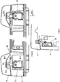
Figures 5-10 respectively represent a cross-sectional front and side views of the housing; -
Figures 11-12 represent two cross-sectional views of the zones, respectively, front and rear, for closing the bin; -
Figures 13-14 represent two views, respectively cross-sectional front and side, of the system for engaging the lid; -
Figure 15 represent a cross-sectional view of the key locking group; -
Figure 16 represents a detailed view of the wheel-lock group. - As observable in
figure 1 , the bin according to the invention is made up of two containers, an outer covering container and aninner container 2 for collecting waste and also has a rigid frame, indicated withreference 3, arranged in the gap between said two containers, which rest with the four stanchions 3.1 on the bottom of the moreouter container 1, where thewheels 4 are applied: advantageously, upon request by the user, at least two wheels are provided with locking motor group 4.1. - A plurality of
load cells 5, which support the moreinner container 2, so as to detect the weight of the waste deposited by the user into the bin is arranged on the upper edge 3.2 of theframe 3; said load cells are three or more, depending on the size of the bin. - The structure of the bin is completed with a
housing 6 which, positioned at the upper part of theinner container 2, covers the upper edge thereof on the four sides 2.1, so as to reduce the gap between the two containers to a minimum. - The
housing 6 has a double-wall section, which allows holding the operating members of the bin indicated in their entirety withreference 7 and the twolid locking groups 8 for locking thelid 9. - Said
housing 6 andlid 9 are mutually hinged throughhinges 10 made integral with brackets 3.3 of therigid frame 3. - More in detail, as observable in
figure 3 , thehousing 6 has a closed-section profile and variably-shaped configuration which allows, at the front portion and accessible to the user from outside, to obtain a gap for the insertion of the battery "B" (seefigure 6 ), a gap for the insertion of the electronic control unit "E" (seefigure 7 ) and themotorised group 20 for locking the user key (seefigure 8 ) and furthermore, still at the front portion, but internally, also the positioning of the two lid locking groups 8 (seefigures 9-10 ). - Still on the
housings 6 there is positioned the photovoltaic cell "S". - Furthermore, as observable in
figures 11-12 , the upper edge L2 of theinner container 2 is higher with respect to the upper edge L1 of the housing 6: such configuration prevents an ill-intentioned subject from depositing the waste bag withholding it with a cord hence altering the weight thereof in that said cord, when the lid closes always operates on the edge of the inner container, which is supported by the load cells. - As observable in
figures 13-14 , the twolid locking groups 8, arranged at the two ends of the bin, are constituted by two opposite hooks 8.1 which, at closing position, are engaged with the pins 8.2 each arranged in a gap 8.3, obtained in thelid 9; each of said hooks is actuated by a gearmotor 8.4 adjusted through a lid closing sensor 8.5, all being totally inaccessible from the outside. - As observable in
figure 15 , the opening/closure of the lid of the bin is adjusted through a motorised user key locking group, indicated withreference 20, inserted in the front gap of thehousing 6 made up of abody 21 containing anelectronic card 22 for reading a key "K" and a motor, which actuates a key locking actuator, all operating in such a manner that the electronic transponder key, besides allowing the personalised opening of the lid, also allows the blocking of the real key in the slot over the entire period of time of depositing, withdrawal thereof being possible solely upon the closure of the lid again. - As observable in
figure 16 , the locking of the wheel is obtained through a locking motor group 4.1, which actuates a cam 4.2, which is engaged on a pin 4.3 for locking said wheel. - Lastly, as observable in
figures 3 and 4 , the bin is provided, at the lower part thereof, with anadditional volume 30, obtained with a particular shaping of the bottom of theouter container 1, so as to enable having - considering the same outer overall dimension - a considerably greater useful inner space. - The invention thus conceived, can be subjected to numerous modifications and variants; details thereof can be replaced by technically equivalent elements, just like the materials used for providing the two containers can be different, as along the entirety falls within the invention concept defined by the following claims.
Claims (8)
- BIN FOR COLLECTING SOLID WASTE, in particular urban waste, comprising two containers, an outer covering container (1) and an inner container (2) for collecting waste, a rigid frame (3), arranged in the gap between said two containers (1, 2), said rigid frame (3) resting with four stanchions (3.1) on the bottom of the more outer covering container (1), where four wheels (4) are applied, and a plurality of load cells (5) arranged on the upper edge (3.2) of the rigid frame (3) to support the most inner container (2), so as to be able to detect the weight of the waste deposited in the bin by the user.
- BIN, according to claim 1, characterised by a lid (9) and a housing (6) positioned at the upper part of the inner container (2) covering the upper edge (L2) thereof on four sides so as to reduce the gap between the two containers (1, 2) to a minimum, said housing (6) having a double wall section containing operating members of the bin and two lid locking groups (8) for locking the lid (9), said lid (9) being hinged to the housing (6) through hinges (10), said hinges (10) being fixedly connected to brackets (3.3) of the frame (3).
- BIN, according to claim 2, characterised in that a photovoltaic cell (S) is positioned on the housing (6).
- BIN, according to claim 2, characterised in that the upper edge (L2) of the inner container (2) is higher up than the upper edge (L1) of the housing (6).
- BIN, according to claim 2, characterised in that each of the two lid-locking groups (8) comprise a hook (8.1), said two hooks (8.1) being arranged on the same side of the bin whereby each hook (8.1) engage in the closed position of the lid (9) in a pin (8.2) arranged in a gap (8.3) formed on the lid (9), each of said hooks (8.1) being actuated by a gearmotor (8.4) adjusted through a lid closing sensor (8.5).
- BIN, according to claim 1, characterised in that a motorised user key locking group (20), to regulate the opening/closing of the lid (9), inserted in the front gap of the housing (6), is made up of a body (21), which contains an electronic reading card (22) of a key (K) and a motor (23) that actuates a key locking actuator (24).
- BIN, according to one or more of the previous claims, characterised in that at least two wheels (4) are provided with a locking motor group (4.1) that actuates a cam (4.2) that engages on a pin (4.3) for locking said wheels.
- BIN, according to one or more of the previous claims, characterised in that the bin is equipped, in its lower part, with an additional volume (30), obtained through a particular shaping of the bottom of the outer container (1).
Applications Claiming Priority (2)
| Application Number | Priority Date | Filing Date | Title |
|---|---|---|---|
| ITVI2010A000062A IT1398705B1 (en) | 2010-03-09 | 2010-03-09 | BOX FOR THE COLLECTION OF SOLID WASTE |
| PCT/EP2011/000816 WO2011110283A1 (en) | 2010-03-09 | 2011-02-21 | Bin for collecting solid waste |
Publications (2)
| Publication Number | Publication Date |
|---|---|
| EP2544968A1 EP2544968A1 (en) | 2013-01-16 |
| EP2544968B1 true EP2544968B1 (en) | 2019-12-18 |
Family
ID=42732833
Family Applications (1)
| Application Number | Title | Priority Date | Filing Date |
|---|---|---|---|
| EP11713979.0A Active EP2544968B1 (en) | 2010-03-09 | 2011-02-21 | Bin for collecting solid waste |
Country Status (6)
| Country | Link |
|---|---|
| US (1) | US8757414B2 (en) |
| EP (1) | EP2544968B1 (en) |
| CN (1) | CN102781792B (en) |
| ES (1) | ES2775102T3 (en) |
| IT (1) | IT1398705B1 (en) |
| WO (1) | WO2011110283A1 (en) |
Families Citing this family (10)
| Publication number | Priority date | Publication date | Assignee | Title |
|---|---|---|---|---|
| GB2483302B (en) * | 2010-09-06 | 2015-11-04 | Nicholas Staley | A storage housing for a waste receptacle |
| GB201119308D0 (en) * | 2011-11-09 | 2011-12-21 | Valtra Oy Ab | Tractor cabs |
| CN103910157A (en) * | 2014-02-20 | 2014-07-09 | 厦门红雏鹰商贸有限公司 | Intelligent combined digital measuring platform for garbage bin |
| EP3480137B1 (en) * | 2017-11-06 | 2022-04-13 | Antonio Luigi Piero Maria Foresti | A system for volumetric disposal of waste in road bins |
| GR1009484B (en) * | 2018-02-26 | 2019-03-20 | Γεωργιος Δημητριου Στεγγος | Refuse container with advanced operations |
| IT201800003727A1 (en) * | 2018-03-19 | 2019-09-19 | Ulysses Energy S R L | DEVICE AND SYSTEM FOR WEIGHING WASTE AND METHOD OF OPERATION |
| CN109018639B (en) * | 2018-07-10 | 2024-02-27 | 上海鸿研物流技术有限公司 | Cardboard box |
| US11346704B2 (en) * | 2019-03-19 | 2022-05-31 | AIS Construction Equipment Corporation | Load sensor bucket and related method |
| US11473964B1 (en) * | 2019-10-09 | 2022-10-18 | Carl Emil Donati | Truck tough scale |
| USD1000635S1 (en) * | 2021-10-13 | 2023-10-03 | Brownstonebin Llc | Enclosure |
Family Cites Families (10)
| Publication number | Priority date | Publication date | Assignee | Title |
|---|---|---|---|---|
| US2525587A (en) * | 1946-03-01 | 1950-10-10 | Julius H Cahn | Spring microbalance |
| GB706217A (en) * | 1951-08-28 | 1954-03-24 | Robert Taylor | Improvements in or relating to bins for waste matter |
| DE3700264A1 (en) * | 1987-01-07 | 1987-06-25 | Doerr Wilhelm | Refuse bin opener with pedal actuation |
| US5015021A (en) * | 1990-01-30 | 1991-05-14 | Daniel Wyson | Trash dumpster lock with gravity operated release |
| IT1270738B (en) | 1993-10-28 | 1997-05-07 | Bortolo Bertoldo | Device for collecting and weighing municipal solid wastes |
| DE19536318B4 (en) * | 1995-09-29 | 2004-05-06 | Pts Jena Gmbh | Device for weight-based fee calculation for waste containers |
| US5900592A (en) * | 1997-08-29 | 1999-05-04 | Lockheed Martin Energy Research Corp. | Load sensing system |
| DE19835762A1 (en) * | 1998-08-07 | 2000-02-17 | Meisener Nachrichtentechnik Gm | Refuse container for multiple access has the lid released by a chip card and with the amount of refuse loaded in measured by load sensors on the suspension of the container |
| CN201128584Y (en) * | 2007-09-12 | 2008-10-08 | 许俊 | Environment-friendly intelligent type recyclable garbage device |
| CN201089615Y (en) * | 2007-09-28 | 2008-07-23 | 深圳清华力合传感科技有限公司 | Intelligent dustbin |
-
2010
- 2010-03-09 IT ITVI2010A000062A patent/IT1398705B1/en active
-
2011
- 2011-02-21 US US13/576,746 patent/US8757414B2/en active Active
- 2011-02-21 WO PCT/EP2011/000816 patent/WO2011110283A1/en active Application Filing
- 2011-02-21 CN CN201180012908.9A patent/CN102781792B/en active Active
- 2011-02-21 ES ES11713979T patent/ES2775102T3/en active Active
- 2011-02-21 EP EP11713979.0A patent/EP2544968B1/en active Active
Non-Patent Citations (1)
| Title |
|---|
| None * |
Also Published As
| Publication number | Publication date |
|---|---|
| IT1398705B1 (en) | 2013-03-08 |
| EP2544968A1 (en) | 2013-01-16 |
| ITVI20100062A1 (en) | 2011-09-10 |
| US8757414B2 (en) | 2014-06-24 |
| US20120318791A1 (en) | 2012-12-20 |
| ES2775102T3 (en) | 2020-07-23 |
| CN102781792A (en) | 2012-11-14 |
| CN102781792B (en) | 2014-11-26 |
| WO2011110283A1 (en) | 2011-09-15 |
Similar Documents
| Publication | Publication Date | Title |
|---|---|---|
| EP2544968B1 (en) | Bin for collecting solid waste | |
| CA2775847C (en) | Automated collection point | |
| US9554646B1 (en) | System and methods of preserving integrity and securely transporting biological specimens to a depository and devices for securely storing biological specimens | |
| CA2682837A1 (en) | Secure accumulation/disposal bin | |
| KR101581944B1 (en) | Inputting device for quantity and weight loss of food garbage container | |
| CA2928220A1 (en) | Waste bin platform, waste management system and method for managing waste | |
| US8844705B2 (en) | Cash box system for a vending machine | |
| KR20120003234U (en) | Food garbage processor hopper equipment | |
| ES2921927T3 (en) | A system for volumetric disposal of waste in street containers | |
| JP3091171B2 (en) | Trash can | |
| EP3434620B1 (en) | Modular weighing unit for waste collection system | |
| US20160361721A1 (en) | Medication collection systems and related methods | |
| WO2012099611A1 (en) | Ballot tabulation device with internal tote bin | |
| KR101474359B1 (en) | Low power consumed food-type waste collecting system using battery and food-type waste collecting method using the same | |
| KR100921782B1 (en) | Pick-up device to charge the taxes at a food garbage weight | |
| NL1003506C2 (en) | Container for storing waste or valuable materials, especially in multi-family houses and flats. | |
| KR20130095545A (en) | Container for collecting by specific duty food garbage | |
| KR20110121390A (en) | Food garbage disposal apparatus | |
| WO2012044184A1 (en) | Apparatus and method for the secure receipt of articles | |
| EP2660168B1 (en) | Disposal lock | |
| KR200474482Y1 (en) | Pick-up device to charge the taxes at a food garbage | |
| JP2021038085A (en) | Article collection device | |
| GB2330382A (en) | Secure deposit box | |
| FR2772732A1 (en) | Medical waste collection and disposal system | |
| WO2017151049A1 (en) | Apparatus for handling cash |
Legal Events
| Date | Code | Title | Description |
|---|---|---|---|
| PUAI | Public reference made under article 153(3) epc to a published international application that has entered the european phase |
Free format text: ORIGINAL CODE: 0009012 |
|
| 17P | Request for examination filed |
Effective date: 20120820 |
|
| AK | Designated contracting states |
Kind code of ref document: A1 Designated state(s): AL AT BE BG CH CY CZ DE DK EE ES FI FR GB GR HR HU IE IS IT LI LT LU LV MC MK MT NL NO PL PT RO RS SE SI SK SM TR |
|
| AX | Request for extension of the european patent |
Extension state: BA ME |
|
| 17Q | First examination report despatched |
Effective date: 20131003 |
|
| STAA | Information on the status of an ep patent application or granted ep patent |
Free format text: STATUS: EXAMINATION IS IN PROGRESS |
|
| GRAP | Despatch of communication of intention to grant a patent |
Free format text: ORIGINAL CODE: EPIDOSNIGR1 |
|
| STAA | Information on the status of an ep patent application or granted ep patent |
Free format text: STATUS: GRANT OF PATENT IS INTENDED |
|
| INTG | Intention to grant announced |
Effective date: 20190925 |
|
| GRAS | Grant fee paid |
Free format text: ORIGINAL CODE: EPIDOSNIGR3 |
|
| GRAA | (expected) grant |
Free format text: ORIGINAL CODE: 0009210 |
|
| STAA | Information on the status of an ep patent application or granted ep patent |
Free format text: STATUS: THE PATENT HAS BEEN GRANTED |
|
| AK | Designated contracting states |
Kind code of ref document: B1 Designated state(s): AL AT BE BG CH CY CZ DE DK EE ES FI FR GB GR HR HU IE IS IT LI LT LU LV MC MK MT NL NO PL PT RO RS SE SI SK SM TR |
|
| AX | Request for extension of the european patent |
Extension state: BA ME |
|
| REG | Reference to a national code |
Ref country code: GB Ref legal event code: FG4D |
|
| REG | Reference to a national code |
Ref country code: CH Ref legal event code: EP |
|
| REG | Reference to a national code |
Ref country code: DE Ref legal event code: R096 Ref document number: 602011064072 Country of ref document: DE |
|
| REG | Reference to a national code |
Ref country code: IE Ref legal event code: FG4D |
|
| REG | Reference to a national code |
Ref country code: AT Ref legal event code: REF Ref document number: 1214376 Country of ref document: AT Kind code of ref document: T Effective date: 20200115 |
|
| REG | Reference to a national code |
Ref country code: CH Ref legal event code: NV Representative=s name: VALIPAT S.A. C/O BOVARD SA NEUCHATEL, CH |
|
| REG | Reference to a national code |
Ref country code: SE Ref legal event code: TRGR |
|
| REG | Reference to a national code |
Ref country code: NL Ref legal event code: FP |
|
| PG25 | Lapsed in a contracting state [announced via postgrant information from national office to epo] |
Ref country code: FI Free format text: LAPSE BECAUSE OF FAILURE TO SUBMIT A TRANSLATION OF THE DESCRIPTION OR TO PAY THE FEE WITHIN THE PRESCRIBED TIME-LIMIT Effective date: 20191218 Ref country code: BG Free format text: LAPSE BECAUSE OF FAILURE TO SUBMIT A TRANSLATION OF THE DESCRIPTION OR TO PAY THE FEE WITHIN THE PRESCRIBED TIME-LIMIT Effective date: 20200318 Ref country code: NO Free format text: LAPSE BECAUSE OF FAILURE TO SUBMIT A TRANSLATION OF THE DESCRIPTION OR TO PAY THE FEE WITHIN THE PRESCRIBED TIME-LIMIT Effective date: 20200318 Ref country code: GR Free format text: LAPSE BECAUSE OF FAILURE TO SUBMIT A TRANSLATION OF THE DESCRIPTION OR TO PAY THE FEE WITHIN THE PRESCRIBED TIME-LIMIT Effective date: 20200319 Ref country code: LT Free format text: LAPSE BECAUSE OF FAILURE TO SUBMIT A TRANSLATION OF THE DESCRIPTION OR TO PAY THE FEE WITHIN THE PRESCRIBED TIME-LIMIT Effective date: 20191218 Ref country code: LV Free format text: LAPSE BECAUSE OF FAILURE TO SUBMIT A TRANSLATION OF THE DESCRIPTION OR TO PAY THE FEE WITHIN THE PRESCRIBED TIME-LIMIT Effective date: 20191218 |
|
| REG | Reference to a national code |
Ref country code: LT Ref legal event code: MG4D |
|
| PG25 | Lapsed in a contracting state [announced via postgrant information from national office to epo] |
Ref country code: HR Free format text: LAPSE BECAUSE OF FAILURE TO SUBMIT A TRANSLATION OF THE DESCRIPTION OR TO PAY THE FEE WITHIN THE PRESCRIBED TIME-LIMIT Effective date: 20191218 Ref country code: RS Free format text: LAPSE BECAUSE OF FAILURE TO SUBMIT A TRANSLATION OF THE DESCRIPTION OR TO PAY THE FEE WITHIN THE PRESCRIBED TIME-LIMIT Effective date: 20191218 |
|
| PG25 | Lapsed in a contracting state [announced via postgrant information from national office to epo] |
Ref country code: AL Free format text: LAPSE BECAUSE OF FAILURE TO SUBMIT A TRANSLATION OF THE DESCRIPTION OR TO PAY THE FEE WITHIN THE PRESCRIBED TIME-LIMIT Effective date: 20191218 |
|
| REG | Reference to a national code |
Ref country code: ES Ref legal event code: FG2A Ref document number: 2775102 Country of ref document: ES Kind code of ref document: T3 Effective date: 20200723 |
|
| PG25 | Lapsed in a contracting state [announced via postgrant information from national office to epo] |
Ref country code: PT Free format text: LAPSE BECAUSE OF FAILURE TO SUBMIT A TRANSLATION OF THE DESCRIPTION OR TO PAY THE FEE WITHIN THE PRESCRIBED TIME-LIMIT Effective date: 20200513 Ref country code: EE Free format text: LAPSE BECAUSE OF FAILURE TO SUBMIT A TRANSLATION OF THE DESCRIPTION OR TO PAY THE FEE WITHIN THE PRESCRIBED TIME-LIMIT Effective date: 20191218 Ref country code: CZ Free format text: LAPSE BECAUSE OF FAILURE TO SUBMIT A TRANSLATION OF THE DESCRIPTION OR TO PAY THE FEE WITHIN THE PRESCRIBED TIME-LIMIT Effective date: 20191218 Ref country code: RO Free format text: LAPSE BECAUSE OF FAILURE TO SUBMIT A TRANSLATION OF THE DESCRIPTION OR TO PAY THE FEE WITHIN THE PRESCRIBED TIME-LIMIT Effective date: 20191218 |
|
| PG25 | Lapsed in a contracting state [announced via postgrant information from national office to epo] |
Ref country code: SM Free format text: LAPSE BECAUSE OF FAILURE TO SUBMIT A TRANSLATION OF THE DESCRIPTION OR TO PAY THE FEE WITHIN THE PRESCRIBED TIME-LIMIT Effective date: 20191218 Ref country code: SK Free format text: LAPSE BECAUSE OF FAILURE TO SUBMIT A TRANSLATION OF THE DESCRIPTION OR TO PAY THE FEE WITHIN THE PRESCRIBED TIME-LIMIT Effective date: 20191218 Ref country code: IS Free format text: LAPSE BECAUSE OF FAILURE TO SUBMIT A TRANSLATION OF THE DESCRIPTION OR TO PAY THE FEE WITHIN THE PRESCRIBED TIME-LIMIT Effective date: 20200418 |
|
| REG | Reference to a national code |
Ref country code: DE Ref legal event code: R097 Ref document number: 602011064072 Country of ref document: DE |
|
| PLBE | No opposition filed within time limit |
Free format text: ORIGINAL CODE: 0009261 |
|
| STAA | Information on the status of an ep patent application or granted ep patent |
Free format text: STATUS: NO OPPOSITION FILED WITHIN TIME LIMIT |
|
| PG25 | Lapsed in a contracting state [announced via postgrant information from national office to epo] |
Ref country code: LU Free format text: LAPSE BECAUSE OF NON-PAYMENT OF DUE FEES Effective date: 20200221 Ref country code: DK Free format text: LAPSE BECAUSE OF FAILURE TO SUBMIT A TRANSLATION OF THE DESCRIPTION OR TO PAY THE FEE WITHIN THE PRESCRIBED TIME-LIMIT Effective date: 20191218 Ref country code: MC Free format text: LAPSE BECAUSE OF FAILURE TO SUBMIT A TRANSLATION OF THE DESCRIPTION OR TO PAY THE FEE WITHIN THE PRESCRIBED TIME-LIMIT Effective date: 20191218 |
|
| 26N | No opposition filed |
Effective date: 20200921 |
|
| PG25 | Lapsed in a contracting state [announced via postgrant information from national office to epo] |
Ref country code: SI Free format text: LAPSE BECAUSE OF FAILURE TO SUBMIT A TRANSLATION OF THE DESCRIPTION OR TO PAY THE FEE WITHIN THE PRESCRIBED TIME-LIMIT Effective date: 20191218 |
|
| PG25 | Lapsed in a contracting state [announced via postgrant information from national office to epo] |
Ref country code: IE Free format text: LAPSE BECAUSE OF NON-PAYMENT OF DUE FEES Effective date: 20200221 |
|
| PG25 | Lapsed in a contracting state [announced via postgrant information from national office to epo] |
Ref country code: PL Free format text: LAPSE BECAUSE OF FAILURE TO SUBMIT A TRANSLATION OF THE DESCRIPTION OR TO PAY THE FEE WITHIN THE PRESCRIBED TIME-LIMIT Effective date: 20191218 |
|
| REG | Reference to a national code |
Ref country code: AT Ref legal event code: UEP Ref document number: 1214376 Country of ref document: AT Kind code of ref document: T Effective date: 20191218 |
|
| PG25 | Lapsed in a contracting state [announced via postgrant information from national office to epo] |
Ref country code: TR Free format text: LAPSE BECAUSE OF FAILURE TO SUBMIT A TRANSLATION OF THE DESCRIPTION OR TO PAY THE FEE WITHIN THE PRESCRIBED TIME-LIMIT Effective date: 20191218 Ref country code: MT Free format text: LAPSE BECAUSE OF FAILURE TO SUBMIT A TRANSLATION OF THE DESCRIPTION OR TO PAY THE FEE WITHIN THE PRESCRIBED TIME-LIMIT Effective date: 20191218 Ref country code: CY Free format text: LAPSE BECAUSE OF FAILURE TO SUBMIT A TRANSLATION OF THE DESCRIPTION OR TO PAY THE FEE WITHIN THE PRESCRIBED TIME-LIMIT Effective date: 20191218 |
|
| PG25 | Lapsed in a contracting state [announced via postgrant information from national office to epo] |
Ref country code: MK Free format text: LAPSE BECAUSE OF FAILURE TO SUBMIT A TRANSLATION OF THE DESCRIPTION OR TO PAY THE FEE WITHIN THE PRESCRIBED TIME-LIMIT Effective date: 20191218 |
|
| PGFP | Annual fee paid to national office [announced via postgrant information from national office to epo] |
Ref country code: FR Payment date: 20230113 Year of fee payment: 13 Ref country code: ES Payment date: 20230302 Year of fee payment: 13 Ref country code: CH Payment date: 20230307 Year of fee payment: 13 Ref country code: AT Payment date: 20230116 Year of fee payment: 13 |
|
| PGFP | Annual fee paid to national office [announced via postgrant information from national office to epo] |
Ref country code: SE Payment date: 20230117 Year of fee payment: 13 Ref country code: IT Payment date: 20230113 Year of fee payment: 13 Ref country code: GB Payment date: 20230113 Year of fee payment: 13 Ref country code: DE Payment date: 20230116 Year of fee payment: 13 Ref country code: BE Payment date: 20230116 Year of fee payment: 13 |
|
| PGFP | Annual fee paid to national office [announced via postgrant information from national office to epo] |
Ref country code: NL Payment date: 20230116 Year of fee payment: 13 |