EP2543949A2 - Accumulateur thermique pourvu d'un récipient en partie rempli de liquide - Google Patents
Accumulateur thermique pourvu d'un récipient en partie rempli de liquide Download PDFInfo
- Publication number
- EP2543949A2 EP2543949A2 EP12175312A EP12175312A EP2543949A2 EP 2543949 A2 EP2543949 A2 EP 2543949A2 EP 12175312 A EP12175312 A EP 12175312A EP 12175312 A EP12175312 A EP 12175312A EP 2543949 A2 EP2543949 A2 EP 2543949A2
- Authority
- EP
- European Patent Office
- Prior art keywords
- phase change
- heat accumulator
- heat
- accumulator according
- container
- Prior art date
- Legal status (The legal status is an assumption and is not a legal conclusion. Google has not performed a legal analysis and makes no representation as to the accuracy of the status listed.)
- Withdrawn
Links
Images


Classifications
-
- F—MECHANICAL ENGINEERING; LIGHTING; HEATING; WEAPONS; BLASTING
- F28—HEAT EXCHANGE IN GENERAL
- F28D—HEAT-EXCHANGE APPARATUS, NOT PROVIDED FOR IN ANOTHER SUBCLASS, IN WHICH THE HEAT-EXCHANGE MEDIA DO NOT COME INTO DIRECT CONTACT
- F28D20/00—Heat storage plants or apparatus in general; Regenerative heat-exchange apparatus not covered by groups F28D17/00 or F28D19/00
- F28D20/02—Heat storage plants or apparatus in general; Regenerative heat-exchange apparatus not covered by groups F28D17/00 or F28D19/00 using latent heat
-
- F—MECHANICAL ENGINEERING; LIGHTING; HEATING; WEAPONS; BLASTING
- F24—HEATING; RANGES; VENTILATING
- F24H—FLUID HEATERS, e.g. WATER OR AIR HEATERS, HAVING HEAT-GENERATING MEANS, e.g. HEAT PUMPS, IN GENERAL
- F24H7/00—Storage heaters, i.e. heaters in which the energy is stored as heat in masses for subsequent release
- F24H7/02—Storage heaters, i.e. heaters in which the energy is stored as heat in masses for subsequent release the released heat being conveyed to a transfer fluid
- F24H7/04—Storage heaters, i.e. heaters in which the energy is stored as heat in masses for subsequent release the released heat being conveyed to a transfer fluid with forced circulation of the transfer fluid
-
- F—MECHANICAL ENGINEERING; LIGHTING; HEATING; WEAPONS; BLASTING
- F28—HEAT EXCHANGE IN GENERAL
- F28D—HEAT-EXCHANGE APPARATUS, NOT PROVIDED FOR IN ANOTHER SUBCLASS, IN WHICH THE HEAT-EXCHANGE MEDIA DO NOT COME INTO DIRECT CONTACT
- F28D20/00—Heat storage plants or apparatus in general; Regenerative heat-exchange apparatus not covered by groups F28D17/00 or F28D19/00
- F28D20/0034—Heat storage plants or apparatus in general; Regenerative heat-exchange apparatus not covered by groups F28D17/00 or F28D19/00 using liquid heat storage material
-
- F—MECHANICAL ENGINEERING; LIGHTING; HEATING; WEAPONS; BLASTING
- F24—HEATING; RANGES; VENTILATING
- F24D—DOMESTIC- OR SPACE-HEATING SYSTEMS, e.g. CENTRAL HEATING SYSTEMS; DOMESTIC HOT-WATER SUPPLY SYSTEMS; ELEMENTS OR COMPONENTS THEREFOR
- F24D2220/00—Components of central heating installations excluding heat sources
- F24D2220/10—Heat storage materials, e.g. phase change materials or static water enclosed in a space
-
- F—MECHANICAL ENGINEERING; LIGHTING; HEATING; WEAPONS; BLASTING
- F28—HEAT EXCHANGE IN GENERAL
- F28F—DETAILS OF HEAT-EXCHANGE AND HEAT-TRANSFER APPARATUS, OF GENERAL APPLICATION
- F28F2265/00—Safety or protection arrangements; Arrangements for preventing malfunction
- F28F2265/14—Safety or protection arrangements; Arrangements for preventing malfunction for preventing damage by freezing, e.g. for accommodating volume expansion
-
- Y—GENERAL TAGGING OF NEW TECHNOLOGICAL DEVELOPMENTS; GENERAL TAGGING OF CROSS-SECTIONAL TECHNOLOGIES SPANNING OVER SEVERAL SECTIONS OF THE IPC; TECHNICAL SUBJECTS COVERED BY FORMER USPC CROSS-REFERENCE ART COLLECTIONS [XRACs] AND DIGESTS
- Y02—TECHNOLOGIES OR APPLICATIONS FOR MITIGATION OR ADAPTATION AGAINST CLIMATE CHANGE
- Y02E—REDUCTION OF GREENHOUSE GAS [GHG] EMISSIONS, RELATED TO ENERGY GENERATION, TRANSMISSION OR DISTRIBUTION
- Y02E60/00—Enabling technologies; Technologies with a potential or indirect contribution to GHG emissions mitigation
- Y02E60/14—Thermal energy storage
Definitions
- the invention relates to a heat accumulator, with a partially filled with fluid container, with a system with phase change material, which is used for storing energy.
- Heat storage are used in particular for heating purposes and to provide hot water for a variety of purposes available, especially in households, but also for commercial applications.
- phase change materials often abbreviated as PCM (Phase Change Materials).
- PCM Phase Change Materials
- phase change materials are substances that are used to use the heat content at aggregate change for heat storage.
- Known such substances are, for example, paraffin, which is used in the field of room air conditioning.
- a phase transition is brought about at temperatures above 30 ° C, which when heated from solid to liquid under heat absorption without simultaneous increase in temperature, and takes place during cooling, for example due to heat emission to the environment with crystallization at almost the same and during the process constant temperature.
- phase change material which is arranged in the form of a bed in the interior of a storage container.
- a storage container is proposed, in which cylindrical, unlocked at its end face container with its opening facing downwards are arranged in a storage container and there are flowed around by water or other heat transfer medium.
- phase change material does not undergo chemical reactions with the fluid and does not dissolve in it.
- a generic heat accumulator characterized in that a mixture of two or more substances is used as a phase change material that the mixture has a mixing ratio which at the point of eutectic of the substances involved or within a deviation of +/- 50 % of which is related to the concentrations of the substances involved, and that the mixture has a melting point in the range between 50 ° C and 70 ° C.
- phase change materials are used in a specific selection in or on heat accumulators, in particular in or on so-called layer heat accumulators.
- these mixtures behave largely stably when a phase change is supposed to occur. This means that the two substances melt together or merge together in the solid phase, when the temperature rises or falls.
- a preferred example are mixtures of salts which are also used in other industries.
- the salts magnesium chloride and magnesium nitrate may be mentioned, which may be present as different crystal formations. Both salts may be present individually as anhydrate or in different forms of hydration. All hydration forms have different melting points.
- salts which can be used in this context are, for example, magnesium nitrite, magnesium sulfate, sodium nitrate, sodium nitrite, and iron chloride, iron sulfate or else mixtures of these latter two components.
- Substances and their mixtures in the field of eutectic which are known in the widest range from the field of fertilizers, have proven to be economically interesting and basically usable. These are, for example, urea, calcium nitrate, ammonium sulfate, ammonium nitrate, calcium chloride or else mixtures of, for example, ammonium nitrate and Urea solution. All these phase change materials or latent heat storage or phase change materials are quite inexpensive substances from organic and inorganic chemistry.
- phase change materials can be used, which occur in other industries as waste products.
- a salt mixture with, inter alia, iron chloride sulfate can be used, which serves in the treatment plant area for flocculation support and is widely available.
- the inventive concept is particularly suitable for heat storage, which are constructed as a so-called stratified storage.
- the inventive concepts are particularly suitable for storage systems of solar thermal systems.
- Such systems are known for example from EP 0 384 423 B 1, the EP 1 170 554 B1 and the EP 2 138 776 A2 known.
- a storage container which is designed as a hot water tank, fluids are stored by means of a charging device in a certain layer height, the exact corresponds to their own temperature. As a result, mixing of the fluid inside the hot water tank is avoided.
- the temperatures of the fluid in the various layers are between the temperature of cold water in the lowermost layers and hot water in the uppermost layers of the fluid.
- phase change material in the vicinity of their melting temperature or at melting temperature, especially those who are undergoing a phase change in one or the other direction, if previously just one more or less slight temperature change has occurred in the container.
- a hot water storage tank using stratification technology which is used with the aid of solar energy, is connected inter alia to one or more solar collectors. These provide, for example, towards evening only moderate heat and there are no very high temperatures available.
- the delivered from these solar panels in the evening amount of fluid is inserted at the level in the stratified storage, in which fluid is precisely this temperature. Accordingly, cold water is displaced downwards and the coldest fluid constituents from the reservoir are supplied to the solar collector for further heating.
- such containers with fluids stored in layers use the advantage that they do not increase the entropy existing in the fluid and produce no additional.
- Such hot water tanks are thus optimized in terms of entropy.
- Conventional concepts using phase change material or latent heat storage take no account of this, disturbing the fluids within the container by circulation. As a result, they increase the entropy and have a detrimental effect on the per se advantageous effect of the stored fluids in layers.
- the horizontal laying of bodies in bag form with intermediate distances of approximately 0.5 cm to 5 cm is selected as a particularly favorable and effective installation situation.
- the proportion of bodies with phase change material should be between 20% and 80%, preferably between 40% and 70%, within the entire heat accumulator. If the concentration is still increased above these proportions, or are therefore the bags even closer together, so the exchange of fluids in the vicinity of the bag, so the water or the brine, relatively strongly inhibited and in this way may arise Disruption of the layer effect.
- heat storage systems can be retrofitted with latent heat elements without major installation effort, ie with phase change material and the resulting benefits, even if this was not originally intended.
- the hot water caching of solar systems for domestic use it could be considered as a targeted load case switching on two showers in parallel in a house.
- Heat quantities in the range of 5 kW to 100 kW, preferably from 15 kW to 70 kW, more preferably 40 kW to 60 kW are taken.
- Storage sizes used for these houses are between 100 liters and 10 cubic meters, preferably 300 liters to 1 cubic meter. Tests and considerations have shown that an optimal thickness of pouches to provide heat is between 1 and 3 cm.
- the result is a stable mixture in which a melting point between 50 ° C and 70 ° C can be set.
- a particularly preferred embodiment of the invention has a Housing System for the materials from the phase change materials.
- the bodies have an elastic shell whose elasticity is dimensioned such that it can follow the volume changes of the phase change material.
- the housing system according to the invention offers various advantages.
- One advantage is that the metallic objects, pipes, plates, welds, flanges, nozzles and the like installed in a thermal installation protect against the aggressive behavior of the salts used become.
- salts are advantageously introduced into plastic bags, rubber bags or similar materials and, for example, welded or otherwise sealed hermetically from the surrounding water.
- the shape of the bag can be adapted to the requirements.
- the salts used in the solid state usually have an unfavorably high thermal resistance.
- the heat flowing in from outside can not be distributed or can only be distributed poorly within the solid.
- the withdrawal of the heat storage system shows a similar unfavorable behavior, which leads to the fact that encrustations may result in the cooler performing outer surfaces, which cause a thermal resistance. This thermal resistance hinders the rapid outflow of heat and thus the heat output to the memory.
- the bodies in whose cavity the mixture of the phase change material is located are encased with a multilayer system which has a metallic separating layer on the inside and is encased on both sides with plastic on the outside.
- Such bodies result in particular fusion-tight and long-term stable Housing systems. It should be noted that especially when used in containers of heating technology, the body are exposed to special requirements. Thus, on the one hand, it has to be considered that the bodies must be chemically stable with respect to both the phase change materials in the interior and the externally adjacent fluid.
- As fluid be in Sources of heating technology for heat storage often used brine mixtures that largely consist of water, but also contain additives such as ethylene glycol or propylene glycol or other additives commonly used in solar systems.
- the phase change material which may be present as mentioned in different states of aggregation, for example, as a salt solution.
- the sheath should preferably be diffusion-tight, in order, on the one hand, to diffuse the phase change material from the cavity inside the body into the surrounding fluid and, on the other hand, also to diffuse the additives and also the water from the container into the interior of the body Body to avoid.
- heat should be able to be conducted to enable the phase change material to perform its function, and finally the cost of sheathing the body should not be too high, so as not to interfere with the desired effect of economic usability.
- high-cost stainless steels are less suitable as a wall for the bodies, while on the other hand cost-effective metal sheets likewise precipitate, since they are not chemically resistant enough.
- copper, aluminum and other metals are also less suitable.
- Plastics also present a problem, since even thick-walled plastic pipes tend to be non-diffusion-tight.
- a gradient of saline solution concentration then forms from the cavity in the interior of the bodies through the jacket into the container space with the fluid.
- a sheathing of the body is selected, in which a separation of the plastic coatings is avoided by the metallic separating layer in the interior, so that not through damage but salt solution can get to this metallic separating layer.
- an introduction into the container with the fluid is also possible in other separate, small units.
- an introduction into the known PET bottles from the beverage industry would be possible or other spherical, cylindrical or bottle-shaped elements. These can not only fixed, but alternatively arranged as a loose bed in the heat storage be and are then flowed around outside of the fluid. In any case, it is also ensured that the construction elements of the heat accumulator get no contact with the phase change materials and thus no corrosion problem arises.
- the size of the bodies in all mentioned embodiments is expediently chosen so that the available nominal diameters of the openings in existing heat exchangers are taken into account, so that the bodies do not get into these heat exchangers, if they are loose bodies.
- the desired heat transfer capacities and the appropriate surface as well as the load curves for loading and unloading must also be considered.
- phase change material is in each case differently composed in different levels of level of the container and / or constructed of other materials.
- the heat accumulator is equipped with different phase change materials in different zones.
- a phase change material in the lower part of a heat storage, especially in the lower third, in which often the fluid to be used for heating with temperatures of 30 ° C to 50 ° C itself is also a phase change material is used with a mixture and arrangement, which has its melting point or crystallization point just in this temperature range.
- a phase change material in the upper part of the heat accumulator, in particular in the upper third, which is intended for about a hot water application and a temperature range of 50 ° C to 110 ° C, in particular from 60 ° C to 95 ° C, then, a phase change material having a melting point used in this area.
- temperature ranges can be used, for example in pellet boilers or in solar cooling with phase change materials of different melting points.
- phase change material in this upper range, in particular the salts of magnesium chloride or magnesium nitrate or mixtures thereof are suitable at the point of eutectic of these substances involved.
- the improvement of the heat storage or the increase in the effectiveness of the use of different phase change materials in different heights of the heat storage can be expressed by the fact that a part of the stored heat energy is stored at a higher temperature level. This leads to an increased exergy in the heat storage leads.
- a further or also an alternative improvement of the heat accumulator can arise by using a third or at least another phase change material in the lower region of the heat accumulator. This is particularly advantageous for use in solar operation, that is to say for an uneven energy input for storage. Even in the case of operation with a heat pump so-called low-temperature heat or cold can still be stored with a comparatively high energy density.
- phase change materials with a supercooling effect can take place.
- a use of phase change materials with a supercooling effect can take place.
- the horizontal arrangement of bodies discussed above would have a manufacturing advantage.
- the individual bodies in a temperature layer corresponding to the stratification in the memory would each be identical and could thus be manufactured together. However, different lengths would then have to be produced in the case of a round container cross section within the layer.
- a supercooled melt is used as a phase change material or at least as one of several phase change materials, which changes their state of aggregation by mechanical rapid movement or cavitation or electrical pulse excitation from a liquid to a solid form.
- This is a so-called “latent material”, which tends to a strong hypothermia. This means that heat is extracted from this material in its liquid form, so that the liquid form cools below the melting point, but nevertheless does not crystallize, that is, contrary to the actual temperature state, assumes a liquid form and no solid form.
- phase change material would be sodium acetate.
- the supercooled melt Since the supercooled melt has a relatively low temperature in the liquid state, it also gives off little heat as a loss to the environment. This results in a longer storage is possible with a constant outer insulation.
- This material can be activated, for example via a voltage pulse or a mechanical discharge of a preloaded spring or via another excitation mechanism. At the moment when this activation starts, the phase transformation starts and the latent heat present in the material leads to a temperature rise, which in some applications can well be 30 ° C. This heat released in this way can be delivered to the consumer at a desired time which can be specifically controlled by this activation. This delivery can also be targeted in segments of different activated heat boxes or body and allow a regulated energy release.
- Another embodiment of the invention implements an arrangement of phase change materials, which has hitherto not been contemplated in any form, into practice.
- phase change materials with a mixture close to the eutectic.
- the arrangement is made here such that instead of the outer insulation of storage containers (or within this outer insulation, however, outside of the storage container), a layer of the phase change material is applied.
- a layer of the phase change material is applied for new storage containers, this is easily providable, with existing storage tanks you will lose the existing outer insulation, which is often mounted removable anyway.
- a new layer of insulating material is preferably applied outside this layer.
- An optimal thickness of the layer of phase change material results from the usual removal rate of heat and the loading speed of the existing with the storage tank heat supply or heat extraction.
- the choice of the mixture for the phase change material is the same as in the first embodiment with the bodies arranged in the fluid.
- the same advantages result from the choice of a mixture with a mixing ratio of the individual constituents which is at or in the region of the eutectic of the mixed constituents.
- a mixture that lies in the region of the eutectic can not be separated off and can be built up from abundantly available and comparatively inexpensive salts.
- the storage container provides the power to be provided in the form of heat. This works - if no additional phase change materials are provided in the interior of the storage container, for example in the sense of the above-discussed embodiment of the invention - like a conventional storage container which is filled with a suitable fluid.
- the outer coating of the storage container now supplies the heat consumed from the storage container to the inside at a lower speed.
- excess heat from the interior of the storage container is added to the outer layer with the phase change material when available.
- the coating of the phase change material thus also forms a kind of active insulation.
- this coating is provided on the vertical side walls. This shows the effect that in the liquid portion of the mass of the phase change materials, for example, during heating via a thermosyphon effect, a good mixing of the heat results, which transfers to the surface of the solids.
- incrustations When heat is released into the interior of the memory, incrustations form on the inner wall. However, these incrustations tend to be flushed by the outer liquid phase of the phase change materials into the lower part of the externally applied coating, which is effectively a memory extension.
- phase change material in different levels of the container level is composed differently and / or composed of other materials.
- phase change material consisting of mixtures having a melting point in the range between 50 ° C and 110 ° C, preferably between 60 ° C and 95 ° C. exhibit.
- phase change material consisting of mixtures having a melting point in the range between 5 ° C and 50 ° C, preferably between 30 ° C and 50 ° C have.
- phase change materials are used here outside of the storage container, the others also occur above Context described advantages. If it is a so-called stratified storage, the temperature usually taken at a certain level can be predicted quite well for this area immediately outside the container on the wall. It is also subject to fluctuations in this area, which, however, take place in a very well predictable temperature spectrum and thus make possible the use of phase change material with a different melting point in each different level and thus enable a vote on a particularly effective use.
- Storage tanks are constructed for structural and static reasons usually in a cylinder design, is rarely deviated from the. These cylindrical storage containers usually have diameters that rarely exceed 80 cm or more than 1 m.
- the coating with the phase change materials can advantageously be delivered in the form of half shells, which have a frame and foil tubes. As a result, the diameter of the storage container is subsequently expanded, but also its heat capacity.
- the storage containers can also be in a different design, for example as a cubic container.
- the coating would be made with the phase change material in a shape adapted to this type of construction.
- the unpressurized film tubes can either be factory-filled and transported as Clearausstattersystem, or it can alternatively be transported an empty bag with a corresponding support system in the house in question, to the site or the place of use. There it can then be filled from a tank system with a preheated liquid phase change materials.
- the outer coating or the outer insulation is then subsequently applied subsequently.
- a system of 1.40 m or 1.80 m in diameter can be constructed with the appropriate layers of phase change materials and the outer insulation.
- this area is also operated without pressure. Special costs for pressure reduction or safety devices are therefore not required for this additional coating with phase change materials. These are limited to the anyway required checks of the inner area of the storage container.
- An Indian FIG. 1 illustrated heat accumulator has in particular a container 10.
- the container 10 is a fluid 11th
- the fluid 11 consists essentially of water, in addition it contains additives to set the freezing point far down and to avoid freezing of the fluid in certain situations. Also additives for corrosion protection or other desired behaviors of the fluid 11 are conceivable.
- the container 10 is part of, for example, a heating and water heating system.
- the container 10 is usually cylindrical and 1 m to 2 m high, but other dimensions are conceivable.
- the container 10 (not shown) can be installed, for example, an additional burner, with which the fluid is brought in a certain, usually upper region of the container 10 to higher temperatures.
- the fluid 11 in the container 10 is stored in layers (not shown). That is, the temperature of the fluid 11 is not the same throughout the container, but there is a substantially continuous increase in temperature from the coldest layers at the bottom of the container 10 to the warmest layers at the top of the container 10. Turbulence is avoided as far as possible.
- hot fluid is withdrawn from the uppermost region of the container, which is indicated by a discharge line 15.
- This discharge line 15 removes hot fluid and leads it to further use.
- the further use may be a heat exchanger in which the heat of the fluid is transferred to drinking water, which can then be tapped by the user.
- the discharge line 15 can also be routed to radiators and there ensure the heating of a building. This representation is chosen purely schematically here; It is also possible to use several separate discharge lines 15.
- the fluid 11 By storing in the level or in the layer, the fluid 11 has the exact same temperature, turbulence and disruption of the layer system can be completely avoided.
- a further supply line 17 is indicated schematically.
- fluid 11 is supplied from a solar collector on the roof of the same building in the container. This fluid 11 has been heated in the solar collector on the roof of the building and is now also layered by another layer loader in a level or in a layer of fluids 11 in the container 10, which corresponds exactly to the temperature of this supplied via the supply line 17 fluid.
- Both fluids to be layered from the lines 16 and 17 can also be stored depending on the currently available temperature in time-varying layers when, for example, cooler fluid 11 is made available from the solar collector in the evening than at midday.
- the solar collector is then supplied (not shown), of course, as a replacement for the warmed-up fluid 11 supplied by it, other fluid 11 from the coldest, lowermost region of the container 10.
- the amount of fluid 11 in the container 10 thus remains approximately constant.
- the additional fluids to be layered from the two lines 16 and 17 displace so colder amounts of fluid down and warmer amounts of fluid upwards, with no turbulence arise.
- Phase-change materials 20 are now provided as additional elements. These are in the illustrated embodiment in bodies 25.
- the phase change materials are mixtures of various substances, in particular salts such as magnesium chloride and magnesium nitrate, wherein the mixing ratio is in the vicinity of the eutectic. Since it is phase change material 20 in the bodies 25, these substances take on the supply of heat energy from the environment, this heat energy without increasing their own temperature. Instead, this absorbed heat energy is converted into a phase change, in other words, the mixtures melt, without thereby increasing the temperature. Only after melting does the temperature of the mixtures of the phase change material 20 in the bodies 25 rise.
- the bodies 25 floating or lying in a specific layer of the fluid 11 first convert this temperature increase into a phase change when the temperature in the fluid in this layer rises due to the incorporation of further fluid 11 from the lines 16 or 17, so the temperature in this Layer of the fluid 11 does not rise, but initially remains constant due to the withdrawal into the body 25.
- the temperature in the fluid 11 in the container 10 falls in a certain layer, for example because warm water is withdrawn via line 15 for heating or hot water purposes and accordingly cooled water is returned via the line 16 and thus low temperature water displaces the warmer water upwards.
- the mixture of the phase change material 20 in the interior of the body 25 can now be solid again, such as by crystallization, and thereby release the released energy as heat energy in the surrounding fluid again without reducing the temperature, which therefore does not lower its temperature, but a higher Temperature maintains.
- the multiplicity of bodies 25 within the container 10 means that the majority of these bodies 25 are not involved in the corresponding processes, since only those bodies 25 or the phase change material 20 melt or solidify in them, at which the melting temperature of the phase change material 20 the temperature of the layer of the surrounding fluid 11 corresponds.
- the heat storage with the container 10 in addition, not shown, be provided with a classically constructed buffer, for example, a water supply, which is stored as a preheated subset of the memory in a suitable vessel, which may also be integrated into the main memory.
- a classically constructed buffer for example, a water supply, which is stored as a preheated subset of the memory in a suitable vessel, which may also be integrated into the main memory.
- the heat with the sufficient speed for the particular application provides less than the part of the task with which, in principle, the time-critical supply of heat takes place.
- a larger material thickness in this sense could for example be between 3 cm and 50 cm, preferably between 10 cm and 25 cm.
- the soaking of these thick layers is cheaper.
- One reason for this could be that a thermosiphon effect creates an internal circulation in the liquid portion of the phase change material, which promotes heat transport.
- FIG. 2 another embodiment is shown. Again, one sees the container 10 with the fluid 11 therein, wherein hot fluid 11 is drawn off at the top through the discharge line 15 and cooled fluid down through the return line 16 back into another layer of the fluid 11 in the interior of the container 10 is returned.
- a memory extension 30 in the form of a shell or layer-shaped additional casing on the outside of the container 10th
- This memory extension 30 in turn contains the phase change material 20, ie the mixture of different substances in the region of their eutectic.
- phase change of the phase change material 20 occurs exactly in that area of the memory extension 30, which to the one Layer of the fluid 11 adjacent, which just has the temperature corresponding to the melting temperature of the phase change material 20.
- phase change material 20 in both embodiments of the Figures 1 and 2 is just a mixture of different components with a mixing ratio in the eutectic area, segregation of the components of the phase change material 20 is avoided because all components melt or solidify at the same time. At the same time, it is possible to use very cost-effective and widely available substances which are already in the market as a mixture for completely different purposes, for example in the fertilizer sector, or may require only slight modification.
- FIG. 3 a third embodiment of the invention is shown schematically in a partial section.
- This memory extension 30 consists in the illustrated embodiment of a kind shell with eight shell elements. These shell elements are constructed equal to each other and each have approximately the shape of a parallelepiped. However, the outer surfaces of the parallelepiped here are not flat surfaces, but each bent so as to be able to contact the one hand, the usually round container wall exactly and on the other hand to be able to map the usually also desired as a circle circumference outer wall. In addition to these surfaces are but also those two surfaces which contact the left and right adjacent shell elements formed as curved surfaces. This has a significant advantage when these elements are to be mounted, as will be more apparent below.
- Each of these elements has a dimension of preferably about a height of about 300 to 400 mm, so seen in the vertical direction of the container 10.
- the width, so the dimension in the radial direction to the container is between about 150 mm and 250 mm.
- the extent in the circumferential direction of the container 10 is about 400 to 500 mm. Since the shell of the memory extension 30 in the illustrated embodiment consists of eight shell elements, this results in total here so an outer circumference of the heat storage between 3200 mm and 4000 mm.
- FIG. 4 is given a perspective view of a shell element, as in slightly modified form in the FIG. 3 is used to build the local discs of the memory extension.
- the shell element is again provided with the curved sides.
- hinges are mounted on the outer two vertical edges in the assembled state. These hinges make it easier to place the shell elements next to each other, as in the FIG. 3 is indicated. It is then possible, after releasing the one hinge, to rotate the complete shell element about the other hinge in relation to the circumference of the memory extension 30 and thus to be able to assemble it particularly easily.
- heat conduction devices lead horizontally through the shell element from the inside to the outside.
- These are in particular bars made of preferably graphite.
- these rods pass between the bodies 25 with the phase change material 20, which are not shown in this figure for the sake of simplicity.
- FIG. 4a you can see a view from the outside on the shell element FIG. 4 ,
- the two hinges can be seen on the left and right and one looks at the outward-facing end sides of the heat-conducting devices.
- FIG. 4b is a look directed to the side with which the shell element to the adjacent shell element in the FIG. 3 borders.
- FIG. 4 Various such shell elements from the FIG. 4 then together form a shell for a memory extension 30, as shown in the FIG. 3 is shown in section as a disk and how it is in another embodiment, approximately from the FIG. 2 results.
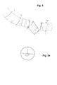
- FIG. 5 is in plan view a chain of four shell elements from the
- FIG. 4 each representing approximately the sight of the Figure 4c Offer. It can be seen again that the shell elements in the assembled state exactly match each other and that lead horizontally for each of these shell elements, the heat conduction.
- One of these shell elements namely the second one from the right, is slightly unscrewed from the row. This actually corresponds to the state during assembly. In fact, the rotation has taken place around the hinge with which this shell element is connected to the shell element arranged to the left, by means of a suspension hinge.
- FIG. 6 a fourth embodiment of the invention is shown. This can also with shell elements, as in the embodiment in the FIGS. 3 to 5 can be constructed shown, but also with other shell elements of a memory extension 30th
- a recess is provided in particular in one of the shell elements, namely for a flange for an additional heat generator.
- a burner or the like can be connected.
- FIG. 6 horizontally through the layer in which the flange for the additional heat generator is located.
- a division into approximately eight shell elements is made on the circumference.
- a container 10 for the heat accumulator with a diameter of about 400 mm to 700 mm, so there is again in the circumferential direction a dimension of 450 mm, for example.
- the dimension of the memory extension 30 is about 200 mm, even with the shell elements off the flange for the additional heat generator. Other dimensions are conceivable if a larger or smaller memory extension 30 is desired.
- heat conducting devices which can also be provided in this embodiment and lead horizontally through the shell elements.
- These heat-conducting elements can be, for example, encapsulated graphite rods.
- a thin insulation can be provided in each case.
- a vacuum insulation is preferably used.
Landscapes
- Engineering & Computer Science (AREA)
- Physics & Mathematics (AREA)
- Thermal Sciences (AREA)
- Mechanical Engineering (AREA)
- General Engineering & Computer Science (AREA)
- Chemical & Material Sciences (AREA)
- Combustion & Propulsion (AREA)
- Central Heating Systems (AREA)
- Building Environments (AREA)
Applications Claiming Priority (1)
| Application Number | Priority Date | Filing Date | Title |
|---|---|---|---|
| DE102011107270A DE102011107270A1 (de) | 2011-07-06 | 2011-07-06 | Wärmespeicher mit einem teilweise mit Fluid gefülltem Behälter |
Publications (1)
| Publication Number | Publication Date |
|---|---|
| EP2543949A2 true EP2543949A2 (fr) | 2013-01-09 |
Family
ID=46466267
Family Applications (1)
| Application Number | Title | Priority Date | Filing Date |
|---|---|---|---|
| EP12175312A Withdrawn EP2543949A2 (fr) | 2011-07-06 | 2012-07-06 | Accumulateur thermique pourvu d'un récipient en partie rempli de liquide |
Country Status (2)
| Country | Link |
|---|---|
| EP (1) | EP2543949A2 (fr) |
| DE (1) | DE102011107270A1 (fr) |
Cited By (2)
| Publication number | Priority date | Publication date | Assignee | Title |
|---|---|---|---|---|
| DE102013005424A1 (de) | 2013-03-27 | 2014-10-02 | Egon Schmitz | Latentwärmespeicheranordnung |
| EP3121522A1 (fr) * | 2014-03-18 | 2017-01-25 | Panasonic Intellectual Property Management Co., Ltd. | Dispositif d'accumulation de chaleur et dispositif de production d'eau chaude pourvu de celui-ci |
Families Citing this family (4)
| Publication number | Priority date | Publication date | Assignee | Title |
|---|---|---|---|---|
| DE102018004352A1 (de) | 2017-11-06 | 2019-05-09 | Plan Team Gmbh | Entnahme-/Abgabevorrichtung und Verfahren zur Entnahme oder Abgabe eines wärmetragenden Fluids aus einem Speicherbehälter oder in einen Speicherbehälter |
| DE202019105940U1 (de) | 2019-10-25 | 2020-10-27 | Thomas Piller | Wärmespeichereinheit |
| DE102020132176A1 (de) | 2020-12-03 | 2022-06-09 | Christian-Albrechts-Universität zu Kiel - Körperschaft des öffentlichen Rechts | Untertägiges Eisspeichersystem in Grundwasserleitern und Grundwassergeringleitern zur Wärmeversorgung |
| DE102022106951A1 (de) | 2022-03-24 | 2023-09-28 | Thomas Piller | Wärmespeichereinheit |
Citations (6)
| Publication number | Priority date | Publication date | Assignee | Title |
|---|---|---|---|---|
| DE3322956A1 (de) | 1983-06-25 | 1985-01-03 | Anton 7320 Göppingen Reißmüller | Latent-waerme-speicher |
| DE29512743U1 (de) | 1995-08-08 | 1996-12-05 | St Speichertechnologie Gmbh | Latentwärmespeicher |
| DE4315492C2 (de) | 1993-05-10 | 1998-07-09 | Daimler Benz Ag | Latentwärmespeicher und ein Verfahren zur Herstellung desselben |
| DE19502507C2 (de) | 1995-01-27 | 1999-08-05 | Franz Hegele | Latentwärmespeicher |
| EP1170554B1 (fr) | 2000-07-07 | 2006-01-18 | Solvis GmbH & Co. KG | Ensemble et procédé pour préparer de l'eau chaude sanitaire |
| EP2138776A2 (fr) | 2008-06-24 | 2009-12-30 | Solvis GmbH & Co. KG | Agencement et procédé de préparation d'eau potable chaude à l'aide de caloporteur |
Family Cites Families (1)
| Publication number | Priority date | Publication date | Assignee | Title |
|---|---|---|---|---|
| DE3905874A1 (de) | 1989-02-23 | 1990-08-30 | Solvis Energiesysteme Gmbh | Warmwasserspeicher mit einem von brauchwasser durchstroemten heizkreis mit aussen liegendem heizelement und mit einer ladewechselvorrichtung |
-
2011
- 2011-07-06 DE DE102011107270A patent/DE102011107270A1/de not_active Withdrawn
-
2012
- 2012-07-06 EP EP12175312A patent/EP2543949A2/fr not_active Withdrawn
Patent Citations (6)
| Publication number | Priority date | Publication date | Assignee | Title |
|---|---|---|---|---|
| DE3322956A1 (de) | 1983-06-25 | 1985-01-03 | Anton 7320 Göppingen Reißmüller | Latent-waerme-speicher |
| DE4315492C2 (de) | 1993-05-10 | 1998-07-09 | Daimler Benz Ag | Latentwärmespeicher und ein Verfahren zur Herstellung desselben |
| DE19502507C2 (de) | 1995-01-27 | 1999-08-05 | Franz Hegele | Latentwärmespeicher |
| DE29512743U1 (de) | 1995-08-08 | 1996-12-05 | St Speichertechnologie Gmbh | Latentwärmespeicher |
| EP1170554B1 (fr) | 2000-07-07 | 2006-01-18 | Solvis GmbH & Co. KG | Ensemble et procédé pour préparer de l'eau chaude sanitaire |
| EP2138776A2 (fr) | 2008-06-24 | 2009-12-30 | Solvis GmbH & Co. KG | Agencement et procédé de préparation d'eau potable chaude à l'aide de caloporteur |
Cited By (3)
| Publication number | Priority date | Publication date | Assignee | Title |
|---|---|---|---|---|
| DE102013005424A1 (de) | 2013-03-27 | 2014-10-02 | Egon Schmitz | Latentwärmespeicheranordnung |
| EP3121522A1 (fr) * | 2014-03-18 | 2017-01-25 | Panasonic Intellectual Property Management Co., Ltd. | Dispositif d'accumulation de chaleur et dispositif de production d'eau chaude pourvu de celui-ci |
| EP3121522A4 (fr) * | 2014-03-18 | 2017-03-29 | Panasonic Intellectual Property Management Co., Ltd. | Dispositif d'accumulation de chaleur et dispositif de production d'eau chaude pourvu de celui-ci |
Also Published As
| Publication number | Publication date |
|---|---|
| DE102011107270A1 (de) | 2013-01-10 |
Similar Documents
| Publication | Publication Date | Title |
|---|---|---|
| EP2519798B1 (fr) | Dispositif et installation d'accumulation intermédiaire d'énergie thermique | |
| EP2543949A2 (fr) | Accumulateur thermique pourvu d'un récipient en partie rempli de liquide | |
| EP2350549B1 (fr) | Dispositif et installation de stockage temporaire d'énergie thermique | |
| DE102010046482A1 (de) | Wärmetauscher | |
| DE102011004202A1 (de) | Latentwärmespeicherelement und Energiespeicher | |
| AT509274B1 (de) | Latentwärmespeicher mit rührwerk | |
| EP2256451B1 (fr) | Dispositif de stockage de chaleur | |
| EP0578126A2 (fr) | Réservoir d'eau chaude à température non-uniforme avec échangeur de chaleur à contre-courant sans source d'énergie externe | |
| DE3990275C1 (de) | Wärmespeicher, insbesondere Latentwärmespeicher für Kraftfahrzeuge | |
| EP0109043B1 (fr) | Accumulateur de chaleur latente avec un hydrate salin ou un mélange d'hydrates salins et de sels | |
| EP2204618A2 (fr) | Accumulateur thermique d'eau chaude ou usée | |
| DE4007001C2 (de) | Wärmespeicher, insbesondere für durch Motorabwärme gespeiste Kraftfahrzeugheizungen | |
| DE202012006244U1 (de) | Wärmemangementsystem | |
| EP3473943B1 (fr) | Procédé et dispositif de climatisation de pièces à l'aide des éléments en béton à activité thermique | |
| EP3460351B1 (fr) | Appareil de conditionnement d'air mobile à accumulateur de chaleur latente | |
| DE102015205626B4 (de) | Wärmespeicher, Bausatz zu dessen Herstellung und Verfahren zur Wärmespeicherung | |
| EP3249335B1 (fr) | Élément d'accumulateur de chaleur latente, encapsulation pour un matériau à chaleur latente et accumulateur de chaleur latente | |
| CH641542A5 (en) | Heat accumulator | |
| DE3905706A1 (de) | Waermespeicher mit expansionsausnehmungen | |
| EP0079452B1 (fr) | Accumulateur d'énergie pour le stockage de chaleur latente en substances d'accumulation réagissant chimiquement ou substances d'accumulation avec changement de phase | |
| WO2008087033A2 (fr) | Utilisation de corps creux remplis de matières fusibles en tant qu'accumulateurs de chaleur latente | |
| DE102012000143A1 (de) | Verfahren und Vorrichtung zur Wärmeübertragung und Wärmespeicherung unter Nutzung des spezifischen und latenten Wärmeinhaltes von Stoffen | |
| EP4257909B1 (fr) | Unité de stockage de chaleur | |
| DE3324943C2 (fr) | ||
| DE202021003858U1 (de) | Wärmespeichervorrichtung zur Speicherung und Abgabe von Wärmeenergie |
Legal Events
| Date | Code | Title | Description |
|---|---|---|---|
| PUAI | Public reference made under article 153(3) epc to a published international application that has entered the european phase |
Free format text: ORIGINAL CODE: 0009012 |
|
| AK | Designated contracting states |
Kind code of ref document: A2 Designated state(s): AL AT BE BG CH CY CZ DE DK EE ES FI FR GB GR HR HU IE IS IT LI LT LU LV MC MK MT NL NO PL PT RO RS SE SI SK SM TR |
|
| AX | Request for extension of the european patent |
Extension state: BA ME |
|
| 19U | Interruption of proceedings before grant |
Effective date: 20151030 |
|
| 19W | Proceedings resumed before grant after interruption of proceedings |
Effective date: 20170403 |
|
| RAP1 | Party data changed (applicant data changed or rights of an application transferred) |
Owner name: SOLVIS GMBH |
|
| STAA | Information on the status of an ep patent application or granted ep patent |
Free format text: STATUS: THE APPLICATION HAS BEEN PUBLISHED |
|
| STAA | Information on the status of an ep patent application or granted ep patent |
Free format text: STATUS: THE APPLICATION IS DEEMED TO BE WITHDRAWN |
|
| 18D | Application deemed to be withdrawn |
Effective date: 20171003 |