EP2543807B2 - Rotary actuator for moving a swivel swing door, particularly in vehicles - Google Patents
Rotary actuator for moving a swivel swing door, particularly in vehicles Download PDFInfo
- Publication number
- EP2543807B2 EP2543807B2 EP11425180.4A EP11425180A EP2543807B2 EP 2543807 B2 EP2543807 B2 EP 2543807B2 EP 11425180 A EP11425180 A EP 11425180A EP 2543807 B2 EP2543807 B2 EP 2543807B2
- Authority
- EP
- European Patent Office
- Prior art keywords
- rotor shaft
- piston
- rotary actuator
- pressure chamber
- stator
- Prior art date
- Legal status (The legal status is an assumption and is not a legal conclusion. Google has not performed a legal analysis and makes no representation as to the accuracy of the status listed.)
- Active
Links
- 239000012530 fluid Substances 0.000 claims description 17
- 238000005096 rolling process Methods 0.000 claims description 7
- 238000007789 sealing Methods 0.000 claims description 7
- 238000002955 isolation Methods 0.000 claims description 3
- 230000004323 axial length Effects 0.000 claims description 2
- 230000008030 elimination Effects 0.000 description 2
- 238000003379 elimination reaction Methods 0.000 description 2
- 239000000463 material Substances 0.000 description 2
- 238000006073 displacement reaction Methods 0.000 description 1
- 230000005484 gravity Effects 0.000 description 1
- 230000001939 inductive effect Effects 0.000 description 1
- 230000010354 integration Effects 0.000 description 1
- 230000001788 irregular Effects 0.000 description 1
- 238000012986 modification Methods 0.000 description 1
- 230000004048 modification Effects 0.000 description 1
- 230000003287 optical effect Effects 0.000 description 1
- 230000021715 photosynthesis, light harvesting Effects 0.000 description 1
Images


Classifications
-
- F—MECHANICAL ENGINEERING; LIGHTING; HEATING; WEAPONS; BLASTING
- F15—FLUID-PRESSURE ACTUATORS; HYDRAULICS OR PNEUMATICS IN GENERAL
- F15B—SYSTEMS ACTING BY MEANS OF FLUIDS IN GENERAL; FLUID-PRESSURE ACTUATORS, e.g. SERVOMOTORS; DETAILS OF FLUID-PRESSURE SYSTEMS, NOT OTHERWISE PROVIDED FOR
- F15B15/00—Fluid-actuated devices for displacing a member from one position to another; Gearing associated therewith
- F15B15/02—Mechanical layout characterised by the means for converting the movement of the fluid-actuated element into movement of the finally-operated member
- F15B15/06—Mechanical layout characterised by the means for converting the movement of the fluid-actuated element into movement of the finally-operated member for mechanically converting rectilinear movement into non- rectilinear movement
- F15B15/068—Mechanical layout characterised by the means for converting the movement of the fluid-actuated element into movement of the finally-operated member for mechanically converting rectilinear movement into non- rectilinear movement the motor being of the helical type
-
- E—FIXED CONSTRUCTIONS
- E05—LOCKS; KEYS; WINDOW OR DOOR FITTINGS; SAFES
- E05F—DEVICES FOR MOVING WINGS INTO OPEN OR CLOSED POSITION; CHECKS FOR WINGS; WING FITTINGS NOT OTHERWISE PROVIDED FOR, CONCERNED WITH THE FUNCTIONING OF THE WING
- E05F15/00—Power-operated mechanisms for wings
- E05F15/50—Power-operated mechanisms for wings using fluid-pressure actuators
- E05F15/53—Power-operated mechanisms for wings using fluid-pressure actuators for swinging wings
- E05F15/54—Power-operated mechanisms for wings using fluid-pressure actuators for swinging wings operated by linear actuators acting on a helical track coaxial with the swinging axis
-
- E—FIXED CONSTRUCTIONS
- E05—LOCKS; KEYS; WINDOW OR DOOR FITTINGS; SAFES
- E05F—DEVICES FOR MOVING WINGS INTO OPEN OR CLOSED POSITION; CHECKS FOR WINGS; WING FITTINGS NOT OTHERWISE PROVIDED FOR, CONCERNED WITH THE FUNCTIONING OF THE WING
- E05F1/00—Closers or openers for wings, not otherwise provided for in this subclass
- E05F1/08—Closers or openers for wings, not otherwise provided for in this subclass spring-actuated, e.g. for horizontally sliding wings
- E05F1/10—Closers or openers for wings, not otherwise provided for in this subclass spring-actuated, e.g. for horizontally sliding wings for swinging wings, e.g. counterbalance
- E05F1/1008—Closers or openers for wings, not otherwise provided for in this subclass spring-actuated, e.g. for horizontally sliding wings for swinging wings, e.g. counterbalance with a coil spring parallel with the pivot axis
- E05F1/1025—Closers or openers for wings, not otherwise provided for in this subclass spring-actuated, e.g. for horizontally sliding wings for swinging wings, e.g. counterbalance with a coil spring parallel with the pivot axis with a compression or traction spring
-
- E—FIXED CONSTRUCTIONS
- E05—LOCKS; KEYS; WINDOW OR DOOR FITTINGS; SAFES
- E05Y—INDEXING SCHEME RELATING TO HINGES OR OTHER SUSPENSION DEVICES FOR DOORS, WINDOWS OR WINGS AND DEVICES FOR MOVING WINGS INTO OPEN OR CLOSED POSITION, CHECKS FOR WINGS AND WING FITTINGS NOT OTHERWISE PROVIDED FOR, CONCERNED WITH THE FUNCTIONING OF THE WING
- E05Y2900/00—Application of doors, windows, wings or fittings thereof
- E05Y2900/50—Application of doors, windows, wings or fittings thereof for vehicles
- E05Y2900/506—Application of doors, windows, wings or fittings thereof for vehicles for buses
-
- E—FIXED CONSTRUCTIONS
- E05—LOCKS; KEYS; WINDOW OR DOOR FITTINGS; SAFES
- E05Y—INDEXING SCHEME RELATING TO HINGES OR OTHER SUSPENSION DEVICES FOR DOORS, WINDOWS OR WINGS AND DEVICES FOR MOVING WINGS INTO OPEN OR CLOSED POSITION, CHECKS FOR WINGS AND WING FITTINGS NOT OTHERWISE PROVIDED FOR, CONCERNED WITH THE FUNCTIONING OF THE WING
- E05Y2900/00—Application of doors, windows, wings or fittings thereof
- E05Y2900/50—Application of doors, windows, wings or fittings thereof for vehicles
- E05Y2900/53—Application of doors, windows, wings or fittings thereof for vehicles characterised by the type of wing
- E05Y2900/531—Doors
Definitions
- the present invention relates to a rotary actuator for moving a swivel swing door, particularly for vehicles, such as buses and trains.
- the swivel swing door for a vehicle is connected by means of swivel arms to a rotary column and can be displaced, by a rotational and lifting movement of the rotary column, to a closing and locking position in which locking means of the door and swing frame are engaged.
- the movement of the rotary column is carried out by means of a rotary actuator which comprises a linear actuator and a screw drive which turns the actuator linear movement into a rotary movement.
- DE3705369 describes a know example of a rotary actuator for moving a swivel swing door in a vehicle, wherein the linear actuator comprises a fluid dynamic piston-cylinder unit and the screw drive is formed externally of the linear actuator and comprises a female screw member which accommodates a cam shaft by the interposition of a set of spheres.
- the connection of the piston to the female screw member is carried out by means of a stem extending from the piston within the cylinder to the female screw member outside of the cylinder.
- the spheres interposed between the female screw member and the cam shaft only partially work under rolling friction and cause a considerable amount of sliding friction which results in energy dissipation and wear phenomena, which, in turn, make it necessary to further increase both the drive stroke (due to a reduction in the thread pitch) and the cam shaft diameter.
- the object of the present invention is thus to provide a rotary actuator for moving a swivel swing door, particularly for vehicles, such as buses, having such characteristics as to overcome the drawbacks mentioned with reference to the prior art.
- a particular object of the invention is to provide a rotary actuator which is more compact in terms of length and/or width.
- a still further object of the invention is to provide a rotary actuator having a simplified and sturdy structure which is efficient in terms of power consumption.
- a rotary actuator for moving a swivel swing door, particularly for vehicles, said rotary actuator having the features of claim 1 and defining a rotation axis and comprising:
- a rotary actuator 1 for moving a swivel swing door 2, particularly for vehicles, is generally referenced 1.
- the rotary actuator 1 defines a rotation axis 3 and comprises a fluid dynamic linear actuator 4 with a cylinder 5 defining an annular pressure chamber 6 therein and an annular piston 7 accommodated within the pressure chamber 6 in a sliding manner parallel to the rotation axis 3.
- the rotary actuator 1 further comprises a screw drive 8 with a stator 9 being fastened such as not to rotate about the rotation axis 3 and connected to the piston 7 such as to translate together with the piston 7 in a direction parallel to the rotation axis 3, as well as a rotor shaft 10 engaged with the stator 9 by means of one or more revolving members 11 and configured such as to rotate about the rotation axis 3 in response to the translation of the stator 9.
- the rotor shaft 10 provides an inner surface 12 of the cylinder 5 and directly defines the pressure chamber 6, the piston 7 being in sealing sliding contact to the inner surface 12.
- the rotor shaft 10 is co-axially integrated in the fluid dynamic actuator 4 and the inner surface 12 provides an inner circumferential surface of the annular pressure space 6.
- the concentrical arrangement of the rotor shaft 10 within the linear actuator 4 relative to the annular pressure chamber 6 minimizes the outer diameter of the pressure chamber, with the axial pressure surface and diameter of the rotor shaft 10 being equal, and allows defining the annular pressure chamber 6 by means of a simple outer tubular wall 13 which is radially positioned outside the rotor shaft 10.
- the fluid dynamic actuator 4 can be configured as a double-effect actuator wherein the pressure chamber 6 is divided by the piston 7 into a first pressure chamber 6A and a second pressure chamber 6B which are arranged on opposite sides of the piston 7.
- the rotor shaft 10 can directly define a part of both first 6A and second 6B pressure chambers.
- the translatable stator 9, the revolving members 11 and a cam surface 14 (or race) engaged by them are accommodated within the annular pressure chamber 6.
- the area in which the translational motion is turned into a rotary motion is completely enclosed within the pressure chamber 6 of the fluid dynamic linear actuator 4, thereby allowing to provide one outer housing 15 only for the entire rotary actuator 1, the side and end walls thereof being capable of directly defining also the pressure chamber.
- the revolving members 11 comprise a pin 16 being provided at the translating stator 9 and a bush 17 pivotally supported on the pin by means of the interposition of a set of (cylindrical) rolls and having a cam-follower surface 18 which engages by rolling contact the cam surface 14 provided in the rotor shaft 10.
- the revolving members 11 are thus formed by (cylindrical) rolling bearings, the inner support thereof (pin 16) being connected to the stator 9 and the outer ring (bush 17) thereof forming the cam-follower surface 18 in contact to the cam surface 14 of the rotor shaft 10 or vice versa.
- the orientation of the pin 16 or, in other words, the local rolling axis of the bush 17 is substantially radial relative to the rotation axis 3 which, in turn, corresponds to the longitudinal axis of the rotor shaft 10.
- Two revolving members 11 may be provided in diametrally opposite positions relative to the rotation axis 3 or three revolving members with 120° angular pitch.
- the cam-follower surface 18 is advantageously convex or rounded in the direction of the rolling axis to eliminate the sliding friction due to the rolling differential between the radially outer area of the bush and the radially inner area thereof.
- the actuator 1 comprises an outer housing 15 formed by a tubular wall 13 and two opposite head walls 19 connected to each other and to the tubular wall 13 by means of a plurality of preferably three tie rods 20.
- the head walls 19 radially support the rotor shaft 10, by means of roller bearings 21, and axially, by means of one or two axial roller bearings 22 enclosed within fifth wheels against which a shoulder 23 of the rotor shaft 10 is abutted.
- the tie rods 20 axially extend at an angular pitch (either constant, e.g.
- At least one, preferably both head walls 19 have a central hole through which at least one end 24 is extended, preferably both opposite ends 24 of the rotor shaft 10 outside the housing 15.
- the ends 24 of the rotor shaft 10 can be either grooved or profiled such as to allow an integral connection with a swivel arm 25 of a door 2.
- brackets 26 can be provided for securing the rotary actuator 1 to a utility, particularly a vehicle, for example a bus or railway wagon.
- the piston 7 can comprise an annular body that can be either single-piece or made of several pieces joined to each other, which forms:
- the translatable stator 9 can comprise a tubular portion that forms the stator and can be formed either as one piece with the piston 7 or connected thereto integrally in rotation (for example by means of a key 33).
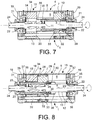
- an (annular) filling body 34 can be advantageously provided which is suitable to reduce, in this region, the volume that can be filled with pressure fluid, with the axial length of the end region ( Fig. 7,8 ) being equal. This allows a fast emptying and a fast pressurization of the fluid volume, e.g. compressed air in that region (for example, during the return-stroke of the piston), without any requirement of sealingly isolating the region from the remaining part of the pressure chamber.
- the return stroke of the piston 7 can be obtained by means of pneumatic or hydrodynamic control (pressurization of the second pressure chamber 6B in the case of a double-effect actuator (shown in the drawings) or, alternatively, by means of a return spring acting on the piston (not illustrated).
- the linear actuator 4 comprises a pneumatic dampening system that slows down the movement of the piston 7 when it enters an end-of-stroke region.
- the cylinder 5 forms a first duct 35 for feeding and draining the pressure fluid, which communicates with a first opening in the pressure chamber 6 and a second feed and drain duct 36 communicating with a second opening in the pressure chamber, wherein the second duct 36 has a throttled section (by means of an adjustment screw 37) relative to the section of the first duct 35.
- the piston 7 forms an isolating annular wall 38 which is adapted to sealingly engage an isolating annular seat 39 (which is possibly provided with a gasket) when the piston 7 enters the end-of-stroke region.
- the isolation annular seat 39 extends between the first opening and the second opening such that, when the piston 7 enters within the end-of-stroke region, the engagement of the isolating wall 38 with the isolating seat 39 separates an air volume within the pressure chamber 6 from the first opening and forces it to pass only through the second opening and the second duct 36 with the throttling. Thereby, the speed of the piston 7 is damped when approaching the end-of-stroke thereof.
- the second duct 36 is connected to the first duct 35 at a downstream location (drain direction) of the throttling, such as to allow a feeding and a pressurization of the pressure fluid (compressed air) through the first duct 35 and first opening, thereby avoiding any undesired slowing down during the initial phases of the movement of piston 7, and accordingly of the door being operated.
- this concept and the structure of the pneumatic damper described herein can be similarly implemented in both pressure chambers 6A, 6B of a double-effect actuator.
- the stator 9 moves past the end of the first length and enters a second length 42 of stroke dedicated to translate or lift the rotor shaft 10
- the axial engagement between the revolving members 11 or the stator 9 and the stop surface 40 causes the rotor shaft 10 to translate axially along with the stator 9 until the total end-of-stroke is reached (represented in Fig. 9 by the abutment surface 43 for example of an upper fifth wheel 22.
- the axial translation of the rotor shaft 10 results to be prevented by the gravity force applied for example by the door connected to the rotor shaft, by a return spring (not illustrated) biasing the rotor shaft axially in a rest position or by a counter-surface being shaped such as to allow for the axial displacement of the rotor shaft 10 only in a predetermined angular position which corresponds to the completion of the rotational movement thereof.
- the rotary actuator 1 provides both for the rotation and translation of the rotor shaft 10 in two well-distinct steps, and hence to the orientation, locking lifting and release lowering of the door to which it is mounted.
- sensors of axial and angular positions can be mounted to the housing 15 of the rotary actuator 1 and interact with the end/s 24 of the rotor shaft 10 which project outwards from the housing 15.
- These sensors can comprise e.g. potentiometric, mechanic, optical ad/or inductive sensors.
- the rotary actuator of the present invention has a number of advantages, particularly it has reduced axial and radial dimensions, a sturdy, though simplified and lightened structure as well as a high energy efficacy in turning the translational movement produced by the linear actuator into a rotational movement of the rotor shaft.
Description
- The present invention relates to a rotary actuator for moving a swivel swing door, particularly for vehicles, such as buses and trains.
- The swivel swing door for a vehicle, such as a bus, is connected by means of swivel arms to a rotary column and can be displaced, by a rotational and lifting movement of the rotary column, to a closing and locking position in which locking means of the door and swing frame are engaged. The movement of the rotary column is carried out by means of a rotary actuator which comprises a linear actuator and a screw drive which turns the actuator linear movement into a rotary movement.
-
DE3705369 describes a know example of a rotary actuator for moving a swivel swing door in a vehicle, wherein the linear actuator comprises a fluid dynamic piston-cylinder unit and the screw drive is formed externally of the linear actuator and comprises a female screw member which accommodates a cam shaft by the interposition of a set of spheres. The connection of the piston to the female screw member is carried out by means of a stem extending from the piston within the cylinder to the female screw member outside of the cylinder. - In this known solution, the stroke of the piston, and accordingly the shortest length of the hydrodynamic cylinder-piston unit adds to the length and diameter of the screw drive which are necessary to achieve the rotation angle and torsional moment as required by the particular application. This makes the actuator axially and radially bulky and often incompatible with the narrow spaces provided in the areas of the transport means doors.
US3255806A describes an actuator in accordance with the preamble ofclaim 1. - Furthermore, the spheres interposed between the female screw member and the cam shaft only partially work under rolling friction and cause a considerable amount of sliding friction which results in energy dissipation and wear phenomena, which, in turn, make it necessary to further increase both the drive stroke (due to a reduction in the thread pitch) and the cam shaft diameter.
- The object of the present invention is thus to provide a rotary actuator for moving a swivel swing door, particularly for vehicles, such as buses, having such characteristics as to overcome the drawbacks mentioned with reference to the prior art.
- Within the primary object, a particular object of the invention is to provide a rotary actuator which is more compact in terms of length and/or width.
- A still further object of the invention is to provide a rotary actuator having a simplified and sturdy structure which is efficient in terms of power consumption.
- This and other objects are achieved by means of a rotary actuator for moving a swivel swing door, particularly for vehicles, said rotary actuator having the features of
claim 1 and defining a rotation axis and comprising: - a fluid dynamic linear actuator with a cylinder defining an annular pressure chamber therein and an annular piston accommodated within the pressure chamber in a sliding manner parallel to the rotation axis,
- a screw drive with a stator which is fastened such as not to rotate about the rotation axis and connected to the piston such as to translate together with the piston in a parallel direction to the rotation axis, as well as a rotor shaft engaged by the stator by means of one or more revolving members and configured such as to rotate about the rotation axis in response to the translation of the stator,
- Due to the integration of the rotor shaft in the structure of the fluid dynamic cylinder a reduction is obtained both in the axial and radial dimensions of the actuator as compared with the rotary actuators of the prior art, as well as the total elimination of at least one wall of the fluid dynamic cylinder. This results in considerable structural simplification of the actuator as well as saving of material and working time required for assembling the same.
- In order to better understand the invention and appreciate the advantages thereof, several exemplary and non-limiting embodiments thereof will be described below with reference to the drawings, in which:
-
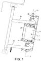
Fig. 1 is a perspective view of a rotary actuator mounted to the door of a transport means; -
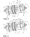
Fig. 2 is a view of a rotary actuator wherein an outer wall has been removed; -
Fig. 3 is a view of a rotary actuator wherein an outer wall and a stator have been removed; -
Fig. 4 shows an enlarged detail of the actuator inFig. 3 ; -
Fig. 5 is a cross-sectional view of a revolving body of the rotary actuator; -
Fig. 6 is a cross-sectional view of a screw drive of the rotary actuator; -
Fig. 7 is a longitudinal sectional view of a rotary actuator in a first operating configuration (retracted piston); -
Fig. 8 is a longitudinal sectional view of the rotary actuator ofFig. 7 in a second operating configuration (forward piston); -
Fig. 9 is a longitudinal sectional view of a rotary actuator according to a preferred embodiment of the invention. - With reference to the figures, a
rotary actuator 1 for moving aswivel swing door 2, particularly for vehicles, is generally referenced 1. - The
rotary actuator 1 defines arotation axis 3 and comprises a fluid dynamiclinear actuator 4 with acylinder 5 defining anannular pressure chamber 6 therein and anannular piston 7 accommodated within thepressure chamber 6 in a sliding manner parallel to therotation axis 3. Therotary actuator 1 further comprises ascrew drive 8 with astator 9 being fastened such as not to rotate about therotation axis 3 and connected to thepiston 7 such as to translate together with thepiston 7 in a direction parallel to therotation axis 3, as well as arotor shaft 10 engaged with thestator 9 by means of one or more revolvingmembers 11 and configured such as to rotate about therotation axis 3 in response to the translation of thestator 9. Therotor shaft 10 provides aninner surface 12 of thecylinder 5 and directly defines thepressure chamber 6, thepiston 7 being in sealing sliding contact to theinner surface 12. - As the
rotor shaft 10 is incorporated within the structure of cylinder 5 a reduction in the axial and radial dimensions, as well as the complete elimination of at least one cylinder fluid dynamic wall are obtained for theactuator 1 as compared with prior art rotary actuators. This results in a considerable structural simplification and in a saving of both material and processing and assembling times. - In accordance with an embodiment, the
rotor shaft 10 is co-axially integrated in the fluiddynamic actuator 4 and theinner surface 12 provides an inner circumferential surface of theannular pressure space 6. - The concentrical arrangement of the
rotor shaft 10 within thelinear actuator 4 relative to theannular pressure chamber 6 minimizes the outer diameter of the pressure chamber, with the axial pressure surface and diameter of therotor shaft 10 being equal, and allows defining theannular pressure chamber 6 by means of a simple outertubular wall 13 which is radially positioned outside therotor shaft 10. - In accordance with a further aspect of the invention, the fluid
dynamic actuator 4 can be configured as a double-effect actuator wherein thepressure chamber 6 is divided by thepiston 7 into afirst pressure chamber 6A and asecond pressure chamber 6B which are arranged on opposite sides of thepiston 7. In this case, therotor shaft 10 can directly define a part of both first 6A and second 6B pressure chambers. Advantageously, also thetranslatable stator 9, the revolvingmembers 11 and a cam surface 14 (or race) engaged by them are accommodated within theannular pressure chamber 6. - Thereby, the area in which the translational motion is turned into a rotary motion is completely enclosed within the
pressure chamber 6 of the fluid dynamiclinear actuator 4, thereby allowing to provide oneouter housing 15 only for the entirerotary actuator 1, the side and end walls thereof being capable of directly defining also the pressure chamber. - This further reduces the overall axial dimensions of the rotary actuator, simplifies and makes the structure thereof lighter and facilitates processing and assembly thereof.
- In accordance with a further embodiment, the revolving
members 11 comprise apin 16 being provided at the translatingstator 9 and abush 17 pivotally supported on the pin by means of the interposition of a set of (cylindrical) rolls and having a cam-follower surface 18 which engages by rolling contact thecam surface 14 provided in therotor shaft 10. - The arrangements of the
pin 16 and cam-surface 14 on therotor shaft 10 and on the translatingstator 9 can be inverted according to the particular design requirements and design choices. - The revolving
members 11 are thus formed by (cylindrical) rolling bearings, the inner support thereof (pin 16) being connected to thestator 9 and the outer ring (bush 17) thereof forming the cam-follower surface 18 in contact to thecam surface 14 of therotor shaft 10 or vice versa. - Advantageously, the orientation of the
pin 16 or, in other words, the local rolling axis of thebush 17 is substantially radial relative to therotation axis 3 which, in turn, corresponds to the longitudinal axis of therotor shaft 10. - Two revolving
members 11 may be provided in diametrally opposite positions relative to therotation axis 3 or three revolving members with 120° angular pitch. - The cam-
follower surface 18 is advantageously convex or rounded in the direction of the rolling axis to eliminate the sliding friction due to the rolling differential between the radially outer area of the bush and the radially inner area thereof. - In accordance with one exemplary embodiment, the
actuator 1 comprises anouter housing 15 formed by atubular wall 13 and twoopposite head walls 19 connected to each other and to thetubular wall 13 by means of a plurality of preferably threetie rods 20. Thehead walls 19 radially support therotor shaft 10, by means ofroller bearings 21, and axially, by means of one or twoaxial roller bearings 22 enclosed within fifth wheels against which ashoulder 23 of therotor shaft 10 is abutted. Thetie rods 20 axially extend at an angular pitch (either constant, e.g. of 120° or irregular depending on the inner space conditions of the device) through theannular pressure chamber 6 provided between the outertubular wall 13 and therotor shaft 10 and provide translation and anti-rotation guides for thepiston 7. At least one, preferably bothhead walls 19 have a central hole through which at least oneend 24 is extended, preferably bothopposite ends 24 of therotor shaft 10 outside thehousing 15. Theends 24 of therotor shaft 10 can be either grooved or profiled such as to allow an integral connection with aswivel arm 25 of adoor 2. - At the
head walls 19 or at theouter wall 13brackets 26 can be provided for securing therotary actuator 1 to a utility, particularly a vehicle, for example a bus or railway wagon. - The
piston 7 can comprise an annular body that can be either single-piece or made of several pieces joined to each other, which forms: - an outer
circumferential surface 27, preferably with one or more seats accommodating outerannular gaskets 28, for sliding and sealing engagement with an outer surface of the cylinder formed by thetubular wall 13, - an inner
circumferential surface 29, preferably with one or more seats accommodating innerannular gaskets 30, for sliding and sealing engagement with theinner surface 12 of the cylinder formed by therotor shaft 10, - as well as a plurality of preferably three
axial holes 31, which are possibly provided withannular gaskets 32, which accommodate theaxial tie rods 20 to fasten thepiston 7 such as not to be capable of rotating about therotation axis 3. - The
translatable stator 9 can comprise a tubular portion that forms the stator and can be formed either as one piece with thepiston 7 or connected thereto integrally in rotation (for example by means of a key 33). - At an end region of the
pressure chamber 6 being defined by thecam surface 14 of the screw drive (and, accordingly, not affected by the movement of the piston) an (annular)filling body 34 can be advantageously provided which is suitable to reduce, in this region, the volume that can be filled with pressure fluid, with the axial length of the end region (Fig. 7,8 ) being equal. This allows a fast emptying and a fast pressurization of the fluid volume, e.g. compressed air in that region (for example, during the return-stroke of the piston), without any requirement of sealingly isolating the region from the remaining part of the pressure chamber. - Thereby, a further structural simplification is obtained as compared with prior art solutions.
- The return stroke of the
piston 7 can be obtained by means of pneumatic or hydrodynamic control (pressurization of thesecond pressure chamber 6B in the case of a double-effect actuator (shown in the drawings) or, alternatively, by means of a return spring acting on the piston (not illustrated). - In accordance with a further aspect of the invention, the
linear actuator 4 comprises a pneumatic dampening system that slows down the movement of thepiston 7 when it enters an end-of-stroke region. - In an embodiment, the
cylinder 5 forms afirst duct 35 for feeding and draining the pressure fluid, which communicates with a first opening in thepressure chamber 6 and a second feed anddrain duct 36 communicating with a second opening in the pressure chamber, wherein thesecond duct 36 has a throttled section (by means of an adjustment screw 37) relative to the section of thefirst duct 35. Furthermore, thepiston 7 forms an isolatingannular wall 38 which is adapted to sealingly engage an isolating annular seat 39 (which is possibly provided with a gasket) when thepiston 7 enters the end-of-stroke region. The isolationannular seat 39 extends between the first opening and the second opening such that, when thepiston 7 enters within the end-of-stroke region, the engagement of the isolatingwall 38 with the isolatingseat 39 separates an air volume within thepressure chamber 6 from the first opening and forces it to pass only through the second opening and thesecond duct 36 with the throttling. Thereby, the speed of thepiston 7 is damped when approaching the end-of-stroke thereof. - In accordance with an embodiment, the
second duct 36 is connected to thefirst duct 35 at a downstream location (drain direction) of the throttling, such as to allow a feeding and a pressurization of the pressure fluid (compressed air) through thefirst duct 35 and first opening, thereby avoiding any undesired slowing down during the initial phases of the movement ofpiston 7, and accordingly of the door being operated. - As shown in
Fig. 7 and 8 , this concept and the structure of the pneumatic damper described herein can be similarly implemented in bothpressure chambers - In accordance with the invention (
Fig. 9 ), at one or preferably both axial ends of thecam surface 14 there is formed astop surface 40 against which the revolvingmembers 11 or thestator 9 are abutted when the end of afirst length 41 of the stroke of the stator 9 (or the piston 7) dedicated to rotate therotor shaft 10 is reached. When thestator 9 moves past the end of the first length and enters asecond length 42 of stroke dedicated to translate or lift therotor shaft 10, the axial engagement between the revolvingmembers 11 or thestator 9 and thestop surface 40 causes therotor shaft 10 to translate axially along with thestator 9 until the total end-of-stroke is reached (represented inFig. 9 by theabutment surface 43 for example of an upperfifth wheel 22. - When the
stator 9 is in thefirst length 41 of stroke (length dedicated to rotation) the axial translation of therotor shaft 10 results to be prevented by the gravity force applied for example by the door connected to the rotor shaft, by a return spring (not illustrated) biasing the rotor shaft axially in a rest position or by a counter-surface being shaped such as to allow for the axial displacement of therotor shaft 10 only in a predetermined angular position which corresponds to the completion of the rotational movement thereof. - Thereby, the
rotary actuator 1 provides both for the rotation and translation of therotor shaft 10 in two well-distinct steps, and hence to the orientation, locking lifting and release lowering of the door to which it is mounted. - Advantageously, sensors of axial and angular positions can be mounted to the
housing 15 of therotary actuator 1 and interact with the end/s 24 of therotor shaft 10 which project outwards from thehousing 15. These sensors can comprise e.g. potentiometric, mechanic, optical ad/or inductive sensors. - The rotary actuator of the present invention has a number of advantages, particularly it has reduced axial and radial dimensions, a sturdy, though simplified and lightened structure as well as a high energy efficacy in turning the translational movement produced by the linear actuator into a rotational movement of the rotor shaft.
- Obviously, to the rotary actuator according to the present invention, those skilled in the art, aiming at meeting specific and contingent requirements, will be able to carry out further modifications and variations, all being encompassed within the scope of protection defined by the annexed claims.
Claims (10)
- A rotary actuator (1) for moving a door (2) particularly a swivel swing door, particularly for vehicles, said rotary actuator (1) defining a rotation axis (3) and comprising:- a fluid dynamic linear actuator (4) with a cylinder (5) internally defining an annular pressure chamber (6), an annular piston (7) accommodated within the pressure chamber (6) in a sliding manner parallel to the rotation axis (3),- a screw drive (8) having a stator (9) fastened such as not to rotate about the rotation axis (3) and connected to the piston (7) such as to translate along with the piston (7) in the direction parallel to the rotation axis (3), and a rotor shaft (10) being engaged with the stator (9) by means of one or more revolving members (11) which engage a cam surface (14) formed in said rotor shaft (10), and the rotor shaft (10) being configured such as to rotate about the rotation axis (3) in response to the translation of the stator (9),wherein the rotor shaft (10) forms an inner surface (12) of the cylinder (5) and directly defines the pressure chamber (6) and in that the piston (7) is in sealing sliding contact with said inner surface (12),
wherein the translatable stator (9), the revolving members (11) and the cam surface (14) engaged by the revolving members (11) are arranged within the annular pressure chamber (6),
wherein the linear actuator (4) is configured as a double-effect actuator and the pressure chamber (6) is divided by the piston (7) in a first pressure chamber (6A) and a second pressure chamber (6B) which are arranged on opposite sides of the piston (7),
characterized in that at both axial ends of the cam surface (14) the rotor shaft (10) forms a stop surface (40) against which the revolving members (11) are abutted when the end of a first length (41) of the stroke of the stator (9) is reached and wherein, when the stator (9) moves past the end of the first length and enters a second length (42) of the stroke thereof, an axial engagement between the revolving members (11) and the stop surface (40) causes the rotor shaft (10) to translate axially along with the stator (9) until reaching a total end-of-stroke,
wherein said first length (41) of the stroke is dedicated to the rotation of the rotor shaft (10) and said second length (42) of the stroke is dedicated to the translation or lifting of the rotor shaft (10),
wherein the rotary actuator (1) comprises means that prevent an axial translation of the rotor shaft (10) when the stator (9) is within the first length (41) of stroke, wherein the rotary actuator (1) comprises an outer housing (15) formed by a tubular wall (13) and two opposite head walls (19), wherein the head walls (19) support the rotor shaft (10) in a radial manner by means of roller bearings (21) and in an axial manner by means of one or two axial roller bearings (22) enclosed within fifth wheels against which a shoulder (23) of the rotor shaft (10) is abutted and wherein an abutment surface 43 of an upper fifth wheel (22) forms said total end - of - stroke,
wherein each of the head walls (19) has a central hole through which the two opposite ends (24) of the rotor shaft (10) extend outwards of the housing (15). - The rotary actuator (1) according to claim 1, wherein the rotor shaft (10) is co-axially connected in the fluid dynamic actuator (4) and the inner surface (12) forms an inner circumferential surface of the annular pressure space (6).
- The rotary actuator (1) according to any preceding claims, wherein the revolving members (11) comprise roller bearings with an inner support (16) connected to the stator (9) and an outer ring (17) forming a cam-follower surface (18) in contact with a cam surface (14) of the rotor shaft (10) or vice versa.
- The rotary actuator (1) according to claim 3, wherein the cam-follower surface (18) is rounded in the direction of a rolling axis thereof.
- The rotary actuator (1) according to any one of the preceding claims, wherein the head walls (19) are connected to each other by means of a plurality of tie rods (20) axially extending through the annular pressure chamber (6) formed between the outer tubular wall (13) and the rotor shaft (10) and forming translational and anti-rotation guides for the piston (7).
- The rotary actuator (1) according to claim 5, wherein the piston (7) comprises an annular body forming:- an outer circumferential surface (27) in sliding and sealing contact with the tubular wall (13),- an inner circumferential surface (29) in sliding and sealing contact to the inner surface (12) of the cylinder being formed by the rotor shaft (10),- a plurality of axial holes (31) accommodating the axial tie rods (20),- a tubular portion forming the translatable stator (9).
- The rotary actuator (1) according to any preceding claim, wherein in an end area of the pressure chamber (6) being defined by a cam surface (14) of the screw drive there is arranged a filling body (34) which reduces the volume that can be filled with the pressure fluid, with the axial length of the end area being equal.
- The rotary actuator (1) according to any preceding claim, wherein the linear actuator (4) comprises a pneumatic dampening system which slows down the movement of the piston (7) when it enters an end-of-stroke area.
- The rotary actuator (1) according to claim 8, wherein the cylinder (5) forms:- a first duct (35) for feeding and draining the pressure fluid in communication with a first opening in the pressure chamber (6), and- a second feeding and drain duct (36) in communication with a second opening within the pressure chamber (6), wherein the second duct (36) has a throttled section relative to the section of the first duct (35),and wherein the piston (7) forms an isolation wall (38) such that, when the piston (7) enters the end-of-stroke area, it sealingly engages an isolation seat (39) extending between the first opening and the second opening such as to separate an air volume within the pressure chamber (6) from the first opening and forcing the latter to be vented only through the second opening and second duct (36).
- The rotary actuator (1) according to claim 9, wherein the second duct (36) is connected to the first duct (35) at a point downstream the throttling as viewed in the draining direction.
Priority Applications (2)
| Application Number | Priority Date | Filing Date | Title |
|---|---|---|---|
| EP11425180.4A EP2543807B2 (en) | 2011-07-06 | 2011-07-06 | Rotary actuator for moving a swivel swing door, particularly in vehicles |
| IL220595A IL220595A (en) | 2011-07-06 | 2012-06-21 | Rotary actuator for moving a swivel swing door, particularly in vehicles |
Applications Claiming Priority (1)
| Application Number | Priority Date | Filing Date | Title |
|---|---|---|---|
| EP11425180.4A EP2543807B2 (en) | 2011-07-06 | 2011-07-06 | Rotary actuator for moving a swivel swing door, particularly in vehicles |
Publications (3)
| Publication Number | Publication Date |
|---|---|
| EP2543807A1 EP2543807A1 (en) | 2013-01-09 |
| EP2543807B1 EP2543807B1 (en) | 2017-07-26 |
| EP2543807B2 true EP2543807B2 (en) | 2020-03-18 |
Family
ID=44651592
Family Applications (1)
| Application Number | Title | Priority Date | Filing Date |
|---|---|---|---|
| EP11425180.4A Active EP2543807B2 (en) | 2011-07-06 | 2011-07-06 | Rotary actuator for moving a swivel swing door, particularly in vehicles |
Country Status (2)
| Country | Link |
|---|---|
| EP (1) | EP2543807B2 (en) |
| IL (1) | IL220595A (en) |
Families Citing this family (2)
| Publication number | Priority date | Publication date | Assignee | Title |
|---|---|---|---|---|
| DE102011052961B4 (en) * | 2011-08-24 | 2017-01-26 | Reinhold Schulte | Fluidic vehicle door swivel drive |
| EP3477032A1 (en) * | 2017-10-24 | 2019-05-01 | Bodo Bode Dogrusan Otomotiv Yan San. VE TIC. A.S. | Rotary drive for a pivotable door leaf |
Citations (4)
| Publication number | Priority date | Publication date | Assignee | Title |
|---|---|---|---|---|
| DE2062135A1 (en) † | 1970-12-17 | 1972-07-06 | Gebr. Bode & Co Vorm. Wegmann & Co, 3500 Kassel-Bettenhausen | Locking device for the door leaf of a swing door, which is pivoted with the help of a rotating column |
| DE102006031477B4 (en) † | 2006-07-07 | 2008-04-17 | Daimler Ag | Rotary drive for hinged door leaves, in particular for vehicle doors |
| DE102007025375A1 (en) † | 2007-05-31 | 2008-12-11 | Schulte, Reinhold, Dipl.-Ing. | stem seal |
| DE102008034994B3 (en) † | 2008-07-25 | 2009-11-12 | Daimler Ag | Rotary drive for swiveling door leaves |
Family Cites Families (7)
| Publication number | Priority date | Publication date | Assignee | Title |
|---|---|---|---|---|
| US3255806A (en) * | 1963-10-03 | 1966-06-14 | Flo Tork Inc | Fluid actuated structure |
| DE3104241A1 (en) * | 1981-02-06 | 1982-08-19 | Eckart GmbH & Co KG, 6490 Schlüchtern | PRESSURE-OPERATED SWIVEL MOTOR |
| FR2528128B1 (en) * | 1982-06-02 | 1985-07-19 | Thiault Jean Claude | HELICOIDAL MOTION CONTROL JACK |
| DE3705369A1 (en) | 1987-02-20 | 1988-09-01 | Bode & Co Geb | ROTARY DRIVE FOR MOVING A SWIVEL DOOR, ESPECIALLY ON VEHICLES |
| FR2637037B1 (en) * | 1988-09-23 | 1993-07-09 | Chorin Christian | DEVICE FOR TRANSFORMING A LINEAR MOTION INTO A ROTARY MOTION WITH THE POSSIBILITY OF REVERSIBILITY, EFFORT AND VARIABLE SPEEDS |
| IT1255184B (en) * | 1992-06-26 | 1995-10-20 | Univer Spa | PNEUMATIC ROTARY ACTUATOR WITH INCREASED TORQUE TORQUE |
| DE102009027794B3 (en) * | 2009-07-17 | 2010-10-28 | Reinhold Schulte | Adjusting device i.e. multiturn actuator, for moving e.g. door leaf of omnibus, has bypass device manually transferred from locking position to passage position, in which bypass device produces connection between operating chambers |
-
2011
- 2011-07-06 EP EP11425180.4A patent/EP2543807B2/en active Active
-
2012
- 2012-06-21 IL IL220595A patent/IL220595A/en active IP Right Grant
Patent Citations (4)
| Publication number | Priority date | Publication date | Assignee | Title |
|---|---|---|---|---|
| DE2062135A1 (en) † | 1970-12-17 | 1972-07-06 | Gebr. Bode & Co Vorm. Wegmann & Co, 3500 Kassel-Bettenhausen | Locking device for the door leaf of a swing door, which is pivoted with the help of a rotating column |
| DE102006031477B4 (en) † | 2006-07-07 | 2008-04-17 | Daimler Ag | Rotary drive for hinged door leaves, in particular for vehicle doors |
| DE102007025375A1 (en) † | 2007-05-31 | 2008-12-11 | Schulte, Reinhold, Dipl.-Ing. | stem seal |
| DE102008034994B3 (en) † | 2008-07-25 | 2009-11-12 | Daimler Ag | Rotary drive for swiveling door leaves |
Also Published As
| Publication number | Publication date |
|---|---|
| EP2543807B1 (en) | 2017-07-26 |
| EP2543807A1 (en) | 2013-01-09 |
| IL220595A (en) | 2016-12-29 |
Similar Documents
| Publication | Publication Date | Title |
|---|---|---|
| CN108290562B (en) | Piston pump group | |
| EP1972470B1 (en) | Air supply device | |
| US20090044645A1 (en) | Motor driven linear actuator | |
| US7926530B2 (en) | Device for generating tire air pressure | |
| US20120217117A1 (en) | Hydrostatic clutch actuator | |
| ITMI960448A1 (en) | SPRING HOLDER IN A VEHICLE CHASSIS | |
| US20060201323A1 (en) | Multiple-stroke hydrostatic axial piston machine | |
| CA2212708C (en) | Rotary actuator | |
| EP3332154A1 (en) | Roller screw mechanism with cage | |
| US4009641A (en) | Compact power steering gear | |
| JP2013092250A (en) | Valve device | |
| EP2543807B2 (en) | Rotary actuator for moving a swivel swing door, particularly in vehicles | |
| EP3324089B1 (en) | Valve operator assembly with clutch mechanism and valve equipped with such assembly | |
| JPS6222B2 (en) | ||
| CN104471249A (en) | Positive displacement pump | |
| EP3262328B1 (en) | Valve operator assembly with double screw mechanism and operable wheel | |
| EP3677797B1 (en) | Actuator with central torque member | |
| CN102947165A (en) | Rotationally supported steering spindle | |
| US5253726A (en) | Steering assembly for utility vehicles | |
| EP2573305B1 (en) | Rotary actuation system for moving a door with orientable wings, in particular in vehicles | |
| WO2016192769A1 (en) | Valve operator assembly with double screw mechanism | |
| CN201784678U (en) | Load discharging device and hydraulic power steering gear with the same | |
| RU2627923C2 (en) | Rotary drive system for door movement with orientable leaves, in particular, in vehicles | |
| KR100378305B1 (en) | Hydraulic Shock Absorber of Steering System using Ball Nut | |
| CN104632373A (en) | Pump device with a vacuum pump and a lubrication pump |
Legal Events
| Date | Code | Title | Description |
|---|---|---|---|
| PUAI | Public reference made under article 153(3) epc to a published international application that has entered the european phase |
Free format text: ORIGINAL CODE: 0009012 |
|
| AK | Designated contracting states |
Kind code of ref document: A1 Designated state(s): AL AT BE BG CH CY CZ DE DK EE ES FI FR GB GR HR HU IE IS IT LI LT LU LV MC MK MT NL NO PL PT RO RS SE SI SK SM TR |
|
| AX | Request for extension of the european patent |
Extension state: BA ME |
|
| 17P | Request for examination filed |
Effective date: 20130614 |
|
| RAX | Requested extension states of the european patent have changed |
Extension state: BA Payment date: 20130614 Extension state: ME Payment date: 20130614 |
|
| RBV | Designated contracting states (corrected) |
Designated state(s): AL AT BE BG CH CY CZ DE DK EE ES FI FR GB GR HR HU IE IS IT LI LT LU LV MC MK MT NL NO PL PT RO RS SE SI SK SM TR |
|
| 17Q | First examination report despatched |
Effective date: 20130729 |
|
| REG | Reference to a national code |
Ref country code: DE Ref legal event code: R079 Ref document number: 602011039905 Country of ref document: DE Free format text: PREVIOUS MAIN CLASS: E05F0015040000 Ipc: E05F0015540000 |
|
| GRAP | Despatch of communication of intention to grant a patent |
Free format text: ORIGINAL CODE: EPIDOSNIGR1 |
|
| RIC1 | Information provided on ipc code assigned before grant |
Ipc: E05F 15/54 20150101AFI20170227BHEP |
|
| INTG | Intention to grant announced |
Effective date: 20170316 |
|
| GRAS | Grant fee paid |
Free format text: ORIGINAL CODE: EPIDOSNIGR3 |
|
| GRAA | (expected) grant |
Free format text: ORIGINAL CODE: 0009210 |
|
| AK | Designated contracting states |
Kind code of ref document: B1 Designated state(s): AL AT BE BG CH CY CZ DE DK EE ES FI FR GB GR HR HU IE IS IT LI LT LU LV MC MK MT NL NO PL PT RO RS SE SI SK SM TR |
|
| AX | Request for extension of the european patent |
Extension state: BA ME |
|
| REG | Reference to a national code |
Ref country code: GB Ref legal event code: FG4D |
|
| RIN1 | Information on inventor provided before grant (corrected) |
Inventor name: TURCATTI, GIANNI Inventor name: SESSA, MASSIMO |
|
| REG | Reference to a national code |
Ref country code: CH Ref legal event code: EP |
|
| REG | Reference to a national code |
Ref country code: AT Ref legal event code: REF Ref document number: 912543 Country of ref document: AT Kind code of ref document: T Effective date: 20170815 |
|
| REG | Reference to a national code |
Ref country code: IE Ref legal event code: FG4D |
|
| REG | Reference to a national code |
Ref country code: DE Ref legal event code: R096 Ref document number: 602011039905 Country of ref document: DE |
|
| REG | Reference to a national code |
Ref country code: NL Ref legal event code: MP Effective date: 20170726 |
|
| REG | Reference to a national code |
Ref country code: LT Ref legal event code: MG4D |
|
| REG | Reference to a national code |
Ref country code: AT Ref legal event code: MK05 Ref document number: 912543 Country of ref document: AT Kind code of ref document: T Effective date: 20170726 |
|
| PG25 | Lapsed in a contracting state [announced via postgrant information from national office to epo] |
Ref country code: NO Free format text: LAPSE BECAUSE OF FAILURE TO SUBMIT A TRANSLATION OF THE DESCRIPTION OR TO PAY THE FEE WITHIN THE PRESCRIBED TIME-LIMIT Effective date: 20171026 Ref country code: LT Free format text: LAPSE BECAUSE OF FAILURE TO SUBMIT A TRANSLATION OF THE DESCRIPTION OR TO PAY THE FEE WITHIN THE PRESCRIBED TIME-LIMIT Effective date: 20170726 Ref country code: AT Free format text: LAPSE BECAUSE OF FAILURE TO SUBMIT A TRANSLATION OF THE DESCRIPTION OR TO PAY THE FEE WITHIN THE PRESCRIBED TIME-LIMIT Effective date: 20170726 Ref country code: SE Free format text: LAPSE BECAUSE OF FAILURE TO SUBMIT A TRANSLATION OF THE DESCRIPTION OR TO PAY THE FEE WITHIN THE PRESCRIBED TIME-LIMIT Effective date: 20170726 Ref country code: HR Free format text: LAPSE BECAUSE OF FAILURE TO SUBMIT A TRANSLATION OF THE DESCRIPTION OR TO PAY THE FEE WITHIN THE PRESCRIBED TIME-LIMIT Effective date: 20170726 Ref country code: FI Free format text: LAPSE BECAUSE OF FAILURE TO SUBMIT A TRANSLATION OF THE DESCRIPTION OR TO PAY THE FEE WITHIN THE PRESCRIBED TIME-LIMIT Effective date: 20170726 Ref country code: NL Free format text: LAPSE BECAUSE OF FAILURE TO SUBMIT A TRANSLATION OF THE DESCRIPTION OR TO PAY THE FEE WITHIN THE PRESCRIBED TIME-LIMIT Effective date: 20170726 |
|
| PG25 | Lapsed in a contracting state [announced via postgrant information from national office to epo] |
Ref country code: ES Free format text: LAPSE BECAUSE OF FAILURE TO SUBMIT A TRANSLATION OF THE DESCRIPTION OR TO PAY THE FEE WITHIN THE PRESCRIBED TIME-LIMIT Effective date: 20170726 Ref country code: GR Free format text: LAPSE BECAUSE OF FAILURE TO SUBMIT A TRANSLATION OF THE DESCRIPTION OR TO PAY THE FEE WITHIN THE PRESCRIBED TIME-LIMIT Effective date: 20171027 Ref country code: LV Free format text: LAPSE BECAUSE OF FAILURE TO SUBMIT A TRANSLATION OF THE DESCRIPTION OR TO PAY THE FEE WITHIN THE PRESCRIBED TIME-LIMIT Effective date: 20170726 Ref country code: PL Free format text: LAPSE BECAUSE OF FAILURE TO SUBMIT A TRANSLATION OF THE DESCRIPTION OR TO PAY THE FEE WITHIN THE PRESCRIBED TIME-LIMIT Effective date: 20170726 Ref country code: IS Free format text: LAPSE BECAUSE OF FAILURE TO SUBMIT A TRANSLATION OF THE DESCRIPTION OR TO PAY THE FEE WITHIN THE PRESCRIBED TIME-LIMIT Effective date: 20171126 Ref country code: RS Free format text: LAPSE BECAUSE OF FAILURE TO SUBMIT A TRANSLATION OF THE DESCRIPTION OR TO PAY THE FEE WITHIN THE PRESCRIBED TIME-LIMIT Effective date: 20170726 Ref country code: BG Free format text: LAPSE BECAUSE OF FAILURE TO SUBMIT A TRANSLATION OF THE DESCRIPTION OR TO PAY THE FEE WITHIN THE PRESCRIBED TIME-LIMIT Effective date: 20171026 |
|
| REG | Reference to a national code |
Ref country code: DE Ref legal event code: R026 Ref document number: 602011039905 Country of ref document: DE |
|
| PLBI | Opposition filed |
Free format text: ORIGINAL CODE: 0009260 |
|
| PG25 | Lapsed in a contracting state [announced via postgrant information from national office to epo] |
Ref country code: DK Free format text: LAPSE BECAUSE OF FAILURE TO SUBMIT A TRANSLATION OF THE DESCRIPTION OR TO PAY THE FEE WITHIN THE PRESCRIBED TIME-LIMIT Effective date: 20170726 Ref country code: CZ Free format text: LAPSE BECAUSE OF FAILURE TO SUBMIT A TRANSLATION OF THE DESCRIPTION OR TO PAY THE FEE WITHIN THE PRESCRIBED TIME-LIMIT Effective date: 20170726 Ref country code: RO Free format text: LAPSE BECAUSE OF FAILURE TO SUBMIT A TRANSLATION OF THE DESCRIPTION OR TO PAY THE FEE WITHIN THE PRESCRIBED TIME-LIMIT Effective date: 20170726 |
|
| PLAX | Notice of opposition and request to file observation + time limit sent |
Free format text: ORIGINAL CODE: EPIDOSNOBS2 |
|
| 26 | Opposition filed |
Opponent name: IWN GMBH & CO. KG Effective date: 20180424 |
|
| PG25 | Lapsed in a contracting state [announced via postgrant information from national office to epo] |
Ref country code: EE Free format text: LAPSE BECAUSE OF FAILURE TO SUBMIT A TRANSLATION OF THE DESCRIPTION OR TO PAY THE FEE WITHIN THE PRESCRIBED TIME-LIMIT Effective date: 20170726 Ref country code: IT Free format text: LAPSE BECAUSE OF FAILURE TO SUBMIT A TRANSLATION OF THE DESCRIPTION OR TO PAY THE FEE WITHIN THE PRESCRIBED TIME-LIMIT Effective date: 20170726 Ref country code: SM Free format text: LAPSE BECAUSE OF FAILURE TO SUBMIT A TRANSLATION OF THE DESCRIPTION OR TO PAY THE FEE WITHIN THE PRESCRIBED TIME-LIMIT Effective date: 20170726 Ref country code: SK Free format text: LAPSE BECAUSE OF FAILURE TO SUBMIT A TRANSLATION OF THE DESCRIPTION OR TO PAY THE FEE WITHIN THE PRESCRIBED TIME-LIMIT Effective date: 20170726 |
|
| REG | Reference to a national code |
Ref country code: FR Ref legal event code: PLFP Year of fee payment: 8 |
|
| PG25 | Lapsed in a contracting state [announced via postgrant information from national office to epo] |
Ref country code: SI Free format text: LAPSE BECAUSE OF FAILURE TO SUBMIT A TRANSLATION OF THE DESCRIPTION OR TO PAY THE FEE WITHIN THE PRESCRIBED TIME-LIMIT Effective date: 20170726 |
|
| PLBB | Reply of patent proprietor to notice(s) of opposition received |
Free format text: ORIGINAL CODE: EPIDOSNOBS3 |
|
| REG | Reference to a national code |
Ref country code: CH Ref legal event code: PL |
|
| PG25 | Lapsed in a contracting state [announced via postgrant information from national office to epo] |
Ref country code: LU Free format text: LAPSE BECAUSE OF NON-PAYMENT OF DUE FEES Effective date: 20180706 Ref country code: MC Free format text: LAPSE BECAUSE OF FAILURE TO SUBMIT A TRANSLATION OF THE DESCRIPTION OR TO PAY THE FEE WITHIN THE PRESCRIBED TIME-LIMIT Effective date: 20170726 |
|
| REG | Reference to a national code |
Ref country code: BE Ref legal event code: MM Effective date: 20180731 |
|
| REG | Reference to a national code |
Ref country code: IE Ref legal event code: MM4A |
|
| PG25 | Lapsed in a contracting state [announced via postgrant information from national office to epo] |
Ref country code: IE Free format text: LAPSE BECAUSE OF NON-PAYMENT OF DUE FEES Effective date: 20180706 Ref country code: LI Free format text: LAPSE BECAUSE OF NON-PAYMENT OF DUE FEES Effective date: 20180731 Ref country code: CH Free format text: LAPSE BECAUSE OF NON-PAYMENT OF DUE FEES Effective date: 20180731 |
|
| PLBP | Opposition withdrawn |
Free format text: ORIGINAL CODE: 0009264 |
|
| PG25 | Lapsed in a contracting state [announced via postgrant information from national office to epo] |
Ref country code: BE Free format text: LAPSE BECAUSE OF NON-PAYMENT OF DUE FEES Effective date: 20180731 |
|
| PG25 | Lapsed in a contracting state [announced via postgrant information from national office to epo] |
Ref country code: MT Free format text: LAPSE BECAUSE OF NON-PAYMENT OF DUE FEES Effective date: 20180706 |
|
| PUAH | Patent maintained in amended form |
Free format text: ORIGINAL CODE: 0009272 |
|
| STAA | Information on the status of an ep patent application or granted ep patent |
Free format text: STATUS: PATENT MAINTAINED AS AMENDED |
|
| 27A | Patent maintained in amended form |
Effective date: 20200318 |
|
| AK | Designated contracting states |
Kind code of ref document: B2 Designated state(s): AL AT BE BG CH CY CZ DE DK EE ES FI FR GB GR HR HU IE IS IT LI LT LU LV MC MK MT NL NO PL PT RO RS SE SI SK SM TR |
|
| AX | Request for extension of the european patent |
Extension state: BA ME |
|
| REG | Reference to a national code |
Ref country code: DE Ref legal event code: R102 Ref document number: 602011039905 Country of ref document: DE |
|
| PG25 | Lapsed in a contracting state [announced via postgrant information from national office to epo] |
Ref country code: TR Free format text: LAPSE BECAUSE OF FAILURE TO SUBMIT A TRANSLATION OF THE DESCRIPTION OR TO PAY THE FEE WITHIN THE PRESCRIBED TIME-LIMIT Effective date: 20170726 |
|
| PG25 | Lapsed in a contracting state [announced via postgrant information from national office to epo] |
Ref country code: PT Free format text: LAPSE BECAUSE OF FAILURE TO SUBMIT A TRANSLATION OF THE DESCRIPTION OR TO PAY THE FEE WITHIN THE PRESCRIBED TIME-LIMIT Effective date: 20170726 Ref country code: HU Free format text: LAPSE BECAUSE OF FAILURE TO SUBMIT A TRANSLATION OF THE DESCRIPTION OR TO PAY THE FEE WITHIN THE PRESCRIBED TIME-LIMIT; INVALID AB INITIO Effective date: 20110706 |
|
| PG25 | Lapsed in a contracting state [announced via postgrant information from national office to epo] |
Ref country code: CY Free format text: LAPSE BECAUSE OF FAILURE TO SUBMIT A TRANSLATION OF THE DESCRIPTION OR TO PAY THE FEE WITHIN THE PRESCRIBED TIME-LIMIT Effective date: 20170726 Ref country code: MK Free format text: LAPSE BECAUSE OF NON-PAYMENT OF DUE FEES Effective date: 20170726 |
|
| PG25 | Lapsed in a contracting state [announced via postgrant information from national office to epo] |
Ref country code: AL Free format text: LAPSE BECAUSE OF FAILURE TO SUBMIT A TRANSLATION OF THE DESCRIPTION OR TO PAY THE FEE WITHIN THE PRESCRIBED TIME-LIMIT Effective date: 20170726 |
|
| PGFP | Annual fee paid to national office [announced via postgrant information from national office to epo] |
Ref country code: GB Payment date: 20220721 Year of fee payment: 12 Ref country code: DE Payment date: 20220620 Year of fee payment: 12 |
|
| PGFP | Annual fee paid to national office [announced via postgrant information from national office to epo] |
Ref country code: FR Payment date: 20220726 Year of fee payment: 12 |
|
| REG | Reference to a national code |
Ref country code: DE Ref legal event code: R119 Ref document number: 602011039905 Country of ref document: DE |
|
| GBPC | Gb: european patent ceased through non-payment of renewal fee |
Effective date: 20230706 |