EP2542829B1 - Vorrichtung zur beleuchtung von räumen - Google Patents
Vorrichtung zur beleuchtung von räumen Download PDFInfo
- Publication number
- EP2542829B1 EP2542829B1 EP11709867.3A EP11709867A EP2542829B1 EP 2542829 B1 EP2542829 B1 EP 2542829B1 EP 11709867 A EP11709867 A EP 11709867A EP 2542829 B1 EP2542829 B1 EP 2542829B1
- Authority
- EP
- European Patent Office
- Prior art keywords
- light
- shaft
- sections
- light deflection
- laminations
- Prior art date
- Legal status (The legal status is an assumption and is not a legal conclusion. Google has not performed a legal analysis and makes no representation as to the accuracy of the status listed.)
- Active
Links
Images


Classifications
-
- F—MECHANICAL ENGINEERING; LIGHTING; HEATING; WEAPONS; BLASTING
- F21—LIGHTING
- F21S—NON-PORTABLE LIGHTING DEVICES; SYSTEMS THEREOF; VEHICLE LIGHTING DEVICES SPECIALLY ADAPTED FOR VEHICLE EXTERIORS
- F21S11/00—Non-electric lighting devices or systems using daylight
-
- F—MECHANICAL ENGINEERING; LIGHTING; HEATING; WEAPONS; BLASTING
- F21—LIGHTING
- F21S—NON-PORTABLE LIGHTING DEVICES; SYSTEMS THEREOF; VEHICLE LIGHTING DEVICES SPECIALLY ADAPTED FOR VEHICLE EXTERIORS
- F21S19/00—Lighting devices or systems employing combinations of electric and non-electric light sources; Replacing or exchanging electric light sources with non-electric light sources or vice versa
- F21S19/005—Combining sunlight and electric light sources for indoor illumination
Definitions
- the invention relates to a device for illuminating rooms with a reflective inner walls having light shaft, at one end of an inlet opening for daylight is present.
- Devices of this type having a reflective inner walls having light shaft, at one end of an inlet opening for daylight is present, with the example, building interiors are illuminated, are known (see, for example EP 1 146 283 ).
- a modular lighting system in which the daylight bundled by a heliostat structure into the interior of a building, where it is routed via a distribution structure to reflectors and of these by stations in premises.
- This distributor structure comprises a number of successively arranged glass plate mirrors, which are individually adjustable in a housing about preferably one axis and forward the beams of light bundled by the heliostat structure in each case to a mirror. But there is no light shaft provided in this lighting system, but only bundled forwarding of light into the building.
- the present invention has the object of providing a device of the type mentioned above, which allows in a simple manner optimal, individual lighting of several rooms.
- the amount of light determined for the individual rooms can be regulated in a simple manner as desired.
- the device 1 according to the invention for illuminating rooms comprises a light shaft 2 which has reflective inner walls 3.
- a vertical light shaft 2 the freestanding or self-supporting, but can also be inserted into an enclosure or a building part.
- the light shaft 2 has at the top of a provided with an insulating glazing 5a and surrounded by a heat insulation 6 inlet opening 5 thermally insulated for daylight, which is indicated by a light beam 10. Furthermore, the light shaft 2 has a plurality of transparent or translucent sections 11, 12, 13, via which the individual rooms can be illuminated by daylight (possibly with additional artificial light, cf., light sources 15 in the upper shaft area).
- the transparent or translucent sections 11, 12, 13 are assigned to light deflection modules 21, 22, 23, which are provided for the deflection of the light in different directions. As in Fig.
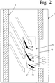
- the Lichtausschungsmodule 21, 22, 23 each comprise a number of fins 25, 26, 27, which at least partially have a reflective surface (they may also, for example, have a white surface in half).
- the number, arrangement, cross section and / or the mutual angle adjustment of the slats 25, 26, 27 of individual light deflection modules 21, 22, 23 may be variable.
- the light deflection modules 21, 22, 23 are connected upstream of the transparent or translucent sections 11, 12, 13, ie they are located on the inside of the light shaft 2.
- the lamellae 25, 26, 27 of individual light deflection modules 21, 22, 23 can be adjusted or pivot about axes 28, 29, 30 and thus adjust the deflection direction of the light beams in the desired manner.
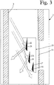
- the slats within the respective light deflection module 21, 22, 23 are adjusted relative to each other, as from Fig. 2 and 3 the example of the fins 25, 26, 27 of the light deflection module 23 can be seen.
- the slats of individual Lichtauslenkungsmodule 21, 22, 23 also be brought into a position in which the light within the light shaft 2 at the sections 11, 12, 13 passed or directed past (see the position of the slats 25, 26, 27 after Fig. 3 ).
- the adjustment or pivoting of the slats 25, 26, 27 can be accomplished manually or with the help of small electric motors with precision gears.
- the adjustment or pivoting is controlled, for example, computer controlled.
- the light shaft 2 can be divided by a glazing 35 into different fire sections or provided with a soundproofing glazing 36, 37 in the wall or in the ground.
- the device according to the invention for the illumination of rooms could also be a horizontally arranged light shaft with in series juxtaposed transparent or translucent sections and include corresponding light deflection modules.
- Fig. 4 shows a device 1 'for the illumination of rooms, in which a lift shaft as the inventive mirrored light shaft 2' with a plurality of superimposed transparent or translucent sections 41, 42, 43 is formed.
- the lift cage 56 which is movable in the lift shaft is equipped with at least one light deflection module 57. The optimization of the desired amount of light is done in the same manner as based on Fig. 1 to Fig. 3 described.
- the blades could in principle be arranged to be movable in the longitudinal direction of the shaft, for example coupled to the elevator car. Conveniently, then the lift door would be glazed and provided above this a glazing, so that the daylight would be passed from above through the lift door.
Landscapes
- Engineering & Computer Science (AREA)
- General Engineering & Computer Science (AREA)
- Life Sciences & Earth Sciences (AREA)
- Sustainable Development (AREA)
- Non-Portable Lighting Devices Or Systems Thereof (AREA)
- Blinds (AREA)
Description
- Die Erfindung betrifft eine Vorrichtung zur Beleuchtung von Räumen mit einem reflektierende Innenwände aufweisenden Lichtschacht, an dessen einem Ende eine Eintrittsöffnung für Tageslicht vorhanden ist.
- Vorrichtungen dieser Art, mit einem reflektierende Innenwände aufweisenden Lichtschacht, an dessen einem Ende eine Eintrittsöffnung für Tageslicht vorhanden ist, mit dem beispielsweise Gebäude-Innenräume beleuchtet werden, sind bekannt (vgl. beispielsweise
EP 1 146 283 ). - Bei einem Beleuchtungs-System nach
US-4,246,477 ist ein Schacht für die Lichtführung vorgesehen. Die Lichtführung erfolgt aber nicht durch reflektierende Innenwände, sondern über diese separaten reflektierenden Spiegeln und Linsen, die nicht verstellbar angeordnet sind. - Gemäss der Druckschrift
US-4,246,477 ist ein modulares Lichtsystem offenbart, bei dem durch eine Heliostatstruktur das Tageslicht gebündelt ins Innere eines Gebäudes, dort via eine Verteilerstruktur zu Reflektoren und von diesen durch Stationen in Räumlichkeiten geleitet wird. Diese Verteilerstruktur umfasst eine Anzahl von hintereinander angeordneten Glasplattenspiegeln, welche in einem Gehäuse um vorzugsweise je eine Achse individuell einstellbar sind und die von der Heliostatstruktur gebündelten Lichtstrahlen jeweils zu einem Spiegel weiterleiten. Es ist aber bei diesem Lichtsystem kein Lichtschacht vorgesehen, sondern nur gebündelte Weiterleitungen des Lichteinfalls ins Gebäude. - Der vorliegenden Erfindung wurde die Aufgabe zugrundegelegt, eine Vorrichtung der eingangs genannten Art zu schaffen, die in einer einfachen Weise eine optimale, individuelle Beleuchtung von mehreren Räumen ermöglicht.
- Die Aufgabe wird erfindungsgemäss durch eine Vorrichtung mit den Merkmalen des Anspruches 1 gelöst.
- Weitere bevorzugte Ausgestaltungen der erfindungsgemässen Vorrichtung bilden den Gegenstand der abhängigen Ansprüche.
- Mit dieser erfindungsgemässen Vorrichtung kann die für die einzelnen Räume bestimmte Lichtmenge in einfacher Weise wie gewünscht reguliert werden.
- Die Erfindung wird nachfolgend anhand der Zeichnung näher erläutert. Es zeigen rein schematisch:
- Fig. 1
- ein erstes Ausführungsbeispiel einer erfindungsgemässen Vorrichtung zur Beleuchtung von Räumen;
- Fig. 2
- eine Ausführungsform eines erfindungsgemässen Lichtauslenkungsmoduls, das einen Teil der Vorrichtung nach
Fig. 1 bildet, in einer ersten Stellung; - Fig. 3
- das Lichtauslenkungsmodul nach
Fig. 2 in einer zweiten Stellung; und - Fig. 4
- ein zweites Ausführungsbeispiel einer erfindungsgemässen Vorrichtung zur Beleuchtung von Räumen.
- Gemäss
Fig.1 umfasst die erfindungsgemässe Vorrichtung 1 zur Beleuchtung von Räumen einen Lichtschacht 2, der reflektierende Innenwände 3 aufweist. Beim dargestellten Ausführungsbeispiel handelt es sich um einen vertikalen Lichtschacht 2, der freistehend oder selbst tragend, aber auch in eine Umhüllung oder einen Gebäudeteil eingeschoben sein kann. - Der Lichtschacht 2 weist am oberen Ende eine mit einer Isolierverglasung 5a versehene und von einer Wärmedämmung 6 umgebene Eintrittsöffnung 5 wärmegedämmt für Tageslicht auf, das mit einem Lichtstrahl 10 angedeutet ist. Ferner weist der Lichtschacht 2 mehrere transparente oder transluzente Teilabschnitte 11, 12, 13 auf, über welche die einzelnen Räume mit dem Tageslicht (allenfalls mit zusätzlicher Kunstlicht unterstützt, vgl. Lichtquellen 15 im oberen Schachtbereich) beleuchtet werden können. Den transparenten oder transluzenten Teilabschnitten 11, 12, 13 sind Lichtauslenkungsmodule 21, 22, 23 zugeordnet, die zur Auslenkung der Licht in verschiedene Richtungen vorgesehen sind. Wie in
Fig. 2 am Beispiel des Lichtauslenkungsmoduls 23 angedeutet, umfassen die Lichtauslenkungsmodule 21, 22, 23 jeweils eine Anzahl von Lamellen 25, 26, 27, die zumindest teilweise eine reflektierende Oberfläche aufweisen (sie können auch z.B. zur Hälfte eine weisse Oberfläche besitzen). Dabei kann die Anzahl, Anordnung, Querschnitt und/oder die gegenseitige Winkeleinstellung der Lamellen 25, 26, 27 einzelner Lichtauslenkungsmodule 21, 22, 23 variabel sein. Die Lichtauslenkungsmodule 21, 22, 23 sind den transparenten oder transluzenten Teilabschnitten 11, 12, 13 vorgeschaltet, d.h. sie befinden sich auf der Innenseite des Lichtschachtes 2. - In einer besonders bevorzugten Weise lassen sich die Lamellen 25, 26, 27 einzelner Lichtauslenkungsmodule 21, 22, 23 verstellen bzw. um Achsen 28, 29, 30 verschwenken und somit die Auslenkungsrichtung der Lichtstrahlen in gewünschter Weise einstellen. Mit Vorteil können auch die Lamellen innerhalb des jeweiligen Lichtauslenkungsmoduls 21, 22, 23 relativ zueinander verstellt werden, wie aus
Fig. 2 und3 am Beispiel der Lamellen 25, 26, 27 des Lichtauslenkungsmoduls 23 ersichtlich. So können die Lamellen einzelner Lichtauslenkungsmodule 21, 22, 23 auch in eine Stellung gebracht werden, in welcher das Licht innerhalb des Lichtschachtes 2 an den Teilabschnitten 11, 12, 13 vorbei weitergeleitet bzw. gelenkt wird (vgl. die Stellung der Lamellen 25, 26, 27 nachFig. 3 ). - Die Verstellung bzw. Verschwenkung der Lamellen 25, 26, 27 kann manuell oder mit Hilfe von kleinen Elektromotoren mit Präzisionsgetrieben bewerkstelligt werden. Vorzugsweise erfolgt die Verstellung bzw. Verschwenkung gesteuert, beispielsweise computergesteuert.
- Auf diese Art und Weise kann die für die einzelnen Räume bestimmte Lichtmenge wie gewünscht optimal reguliert werden.
- Wie in
Fig. 1 angedeutet, kann der Lichtschacht 2 durch eine Verglasung 35 in verschiedene Brandabschnitte unterteilt oder mit einer Schallschutzverglasung 36, 37 in der Wand oder im Boden versehen sein. - Anstelle eines vertikalen Lichtschachtes 2 mit in Serie übereinander angeordneten transparenten oder transluzenten Teilabschnitten 11, 12 13 und den entsprechenden Lichtauslenkungsmodulen 21, 22, 23 könnte die erfindungsgemässe Vorrichtung zur Beleuchtung von Räumen auch einen horizontal angeordneten Lichtschacht mit in Serie nebeneinander angeordneten transparenten oder transluzenten Teilabschnitten und entsprechenden Lichtauslenkungsmodulen umfassen.
-
Fig. 4 zeigt eine Vorrichtung 1' zur Beleuchtung von Räumen, bei der ein Liftschacht als der erfindungsgemässe verspiegelte Lichtschacht 2' mit mehreren übereinander angeordneten transparenten oder transluzenten Teilabschnitten 41, 42, 43 ausgebildet ist. Die im Liftschacht bewegliche Liftkabine 56 ist mit mindestens einem Lichtauslenkungsmodul 57 ausgestattet. Die Optimierung der gewünschten Lichtmenge erfolgt in gleicher Art und Weise wie anhand vonFig. 1 bis Fig. 3 beschrieben. - Die Lamellen könnten im Prinzip in Längsrichtung des Schachtes bewegbar angeordnet sein, beispielsweise gekoppelt mit der Liftkabine. Zweckmässigerweise wäre dann die Lifttüre verglast und oberhalb dieser eine Verglasung vorgesehen, damit das Tageslicht von oben durch die Lifttüre geleitet würde.
Claims (11)
- Vorrichtung zur Beleuchtung von Räumen, mit einem Lichtschacht (2; 2'), an dessen einem Ende eine Eintrittsöffnung (5; 45) für Tageslicht vorhanden ist, wobei Teilabschnitte (11, 12, 13; 41, 42, 43) der Lichtschachtwände transparent oder transluzent ausgebildet sind und im Bereich dieser Lichtauslenkungsmodule (21, 22, 23; 57) zur Auslenkung des Lichtes in verschiedene Richtungen angeordnet sind, dadurch gekennzeichnet, dass
der Lichtschacht (2; 2') reflektierende Innenwände (3) aufweist, wobei diese Lichtauslenkungsmodule (21, 22, 23; 57) jeweils eine Anzahl von Lamellen (25, 26, 27) umfassen, die zumindest teilweise eine reflektierende Oberfläche aufweisen, wobei die Lamellen (25, 26, 27) einzelner Lichtauslenkungsmodule (21, 22, 23; 57) manuell oder mittels eines Antriebs verstellbar bzw. verschwenkbar sind und somit die Auslenkungsrichtung einstellbar ist, und diese Lamellen (25, 26, 27) dabei in eine Stellung bringbar sind, in welcher das Licht innerhalb des Lichtschachtes (2; 2') an den Teilabschnitten (11, 12, 13; 41, 42, 43) vorbei weitergeleitet bzw. gelenkt ist. - Vorrichtung nach Anspruch 1, dadurch gekennzeichnet, dass die Lamellen (25, 26, 27) innerhalb des jeweiligen Lichtauslenkungsmoduls (21, 22, 23; 57) relativ zueinander verstellbar sind.
- Vorrichtung nach Anspruch 1 oder 2, dadurch gekennzeichnet, dass die Anzahl, Anordnung, Querschnitt und/oder die gegenseitige Winkeleinstellung der Lamellen (25, 26, 27) einzelner Lichtauslenkungsmodule (21, 22, 23; 57) variabel ist.
- Vorrichtung nach einem der Ansprüche 1 bis 3, dadurch gekennzeichnet, dass die Lamellen (25, 26, 27) einzelner Lichtauslenkungsmodule (21, 22, 23; 57) gesteuert verstellbar sind.
- Vorrichtung nach einem der Ansprüche 1 bis 4, dadurch gekennzeichnet, dass die Lichtauslenkungsmodule (21, 22, 23; 57) den transparenten oder transluzenten Teilabschnitten (11, 12, 13; 41, 42, 43) vorgeschaltet sind, d.h. sich auf der Innenseite des Lichtschachtes (2; 2') befinden.
- Vorrichtung nach einem der Ansprüche 1 bis 5, dadurch gekennzeichnet, dass der Lichtschacht horizontal angeordnet und die transparenten oder transluzenten Teilabschnitte mit entsprechenden Lichtauslenkungsmodulen in Serie nebeneinander angeordnet sind.
- Vorrichtung nach einem der Ansprüche 1 bis 6, dadurch gekennzeichnet, dass der Lichtschacht (2; 2') vertikal angeordnet und die transparenten oder transluzenten Teilabschnitte (11, 12, 13; 41, 42, 43) mit entsprechenden Lichtauslenkungsmodulen (21, 22, 23; 57) in Serie übereinander angeordnet sind.
- Vorrichtung nach einem der Ansprüche 1 bis 7, dadurch gekennzeichnet, dass der Lichtschacht (2) durch eine Verglasung in verschiedene Brandabschnitte unterteilt oder mit einer Schallschutzverglasung (36, 37) versehen ist.
- Vorrichtung nach Anspruch 7, dadurch gekennzeichnet, dass ein Liftschacht als vertikaler Lichtschacht (2') ausgebildet und mit den transparenten oder transluzenten Teilabschnitten (41, 42, 43) sowie mit den Lichtauslenkungsmodulen (51, 52, 53) ausgerüstet ist.
- Vorrichtung nach Anspruch 1, dadurch gekennzeichnet, dass einer in einem Liftschacht beweglichen Liftkabine (56) mindestens ein sich vorzugsweise mit der Liftkabine mitbewegendes Lichtauslenkungsmodul (57) zugeordnet ist.
- Vorrichtung nach einem der Ansprüche 1 bis 10, dadurch gekennzeichnet, dass der das Tageslicht führende Lichtschacht (2; 2') mit zusätzlichem Kunstlicht beleuchtbar ist.
Applications Claiming Priority (2)
| Application Number | Priority Date | Filing Date | Title |
|---|---|---|---|
| CH00287/10A CH702781B1 (de) | 2010-03-03 | 2010-03-03 | Vorrichtung zur Beleuchtung von Räumen. |
| PCT/EP2011/001005 WO2011107261A1 (de) | 2010-03-03 | 2011-03-02 | Vorrichtung zur beleuchtung von räumen |
Publications (2)
| Publication Number | Publication Date |
|---|---|
| EP2542829A1 EP2542829A1 (de) | 2013-01-09 |
| EP2542829B1 true EP2542829B1 (de) | 2017-10-25 |
Family
ID=44041588
Family Applications (1)
| Application Number | Title | Priority Date | Filing Date |
|---|---|---|---|
| EP11709867.3A Active EP2542829B1 (de) | 2010-03-03 | 2011-03-02 | Vorrichtung zur beleuchtung von räumen |
Country Status (3)
| Country | Link |
|---|---|
| EP (1) | EP2542829B1 (de) |
| CH (1) | CH702781B1 (de) |
| WO (1) | WO2011107261A1 (de) |
Families Citing this family (4)
| Publication number | Priority date | Publication date | Assignee | Title |
|---|---|---|---|---|
| WO2012079177A1 (en) * | 2010-12-16 | 2012-06-21 | Cooledge Lighting Inc. | Hybrid illumination systems and methods |
| CN103669800B (zh) * | 2013-12-27 | 2016-05-04 | 陈璐瑶 | 节能采光通风系统 |
| DE102015223737A1 (de) * | 2015-11-30 | 2017-06-01 | 2Rps Mechatronik Gmbh | Vorrichtung zum indirekten Beleuchten |
| CN114234120B (zh) * | 2021-12-23 | 2024-01-23 | 江苏新鹏能源科技有限公司 | 一种井下维修作业使用的辅助照明装置 |
Citations (1)
| Publication number | Priority date | Publication date | Assignee | Title |
|---|---|---|---|---|
| US4349245A (en) * | 1981-01-29 | 1982-09-14 | Baird Corporation | Modular natural lighting system |
Family Cites Families (4)
| Publication number | Priority date | Publication date | Assignee | Title |
|---|---|---|---|---|
| US4246477A (en) * | 1978-09-18 | 1981-01-20 | R & D Associates | Artificial and solar lighting system |
| DE4439507A1 (de) * | 1994-10-27 | 1996-05-02 | Heiko Schnetz | 3-Komponenten-Beleuchtungssystem |
| DE19604995A1 (de) * | 1996-02-12 | 1997-08-28 | Hermann Leber | System zur ökonomischen und ökologischen Beleuchtung mit Natur- und Kunstlicht |
| CH694470A5 (de) | 2000-04-11 | 2005-01-31 | Heliobus Ag | Anordnung zum Ausleuchten von Räumen in Gebäuden. |
-
2010
- 2010-03-03 CH CH00287/10A patent/CH702781B1/de unknown
-
2011
- 2011-03-02 WO PCT/EP2011/001005 patent/WO2011107261A1/de not_active Ceased
- 2011-03-02 EP EP11709867.3A patent/EP2542829B1/de active Active
Patent Citations (1)
| Publication number | Priority date | Publication date | Assignee | Title |
|---|---|---|---|---|
| US4349245A (en) * | 1981-01-29 | 1982-09-14 | Baird Corporation | Modular natural lighting system |
Also Published As
| Publication number | Publication date |
|---|---|
| WO2011107261A1 (de) | 2011-09-09 |
| EP2542829A1 (de) | 2013-01-09 |
| CH702781A2 (de) | 2011-09-15 |
| CH702781B1 (de) | 2014-11-14 |
Similar Documents
| Publication | Publication Date | Title |
|---|---|---|
| EP0593927B1 (de) | Gestell mit Einsätzen zur Führung von LWL-Kabeln | |
| WO2001059364A1 (de) | Leuchte | |
| DE3513672A1 (de) | Panorama-beobachtungssystem | |
| EP3176494B1 (de) | Leuchtenmodul mit zwei lichtleiter | |
| DE102011057097A1 (de) | Decken-Beleuchtungsanordnung | |
| EP1179158B1 (de) | Leuchte | |
| EP2542829A1 (de) | Vorrichtung zur beleuchtung von räumen | |
| DE69401420T2 (de) | Leuchtleiste | |
| DE3719344A1 (de) | Vorrichtung zur erzeugung eines regenbogens | |
| DE102015205003A1 (de) | Beleuchtungsvorrichtung | |
| EP0453956B1 (de) | Asymmetrisch strahlende Leuchte | |
| EP1968033B1 (de) | Anzeigevorrichtung mit Halteelement | |
| EP0670129B1 (de) | Vitrine mit einer Beleuchtungseinrichtung | |
| DE1806718B2 (de) | Beleuchtungsvorrichtung fuer eine instrumententafel in einem kraftwagen | |
| DE9319537U1 (de) | Beleuchtungsvorrichtung | |
| EP2354635B1 (de) | LED-Fassadenstrahler | |
| DE10045028B4 (de) | Beleuchtungsanlage zur Simulation des Sonnenlichts und ein Verfahren zum Beleuchten eines Beleuchtungsobjektes durch Simulation des Sonnenlichts | |
| EP3540306B1 (de) | Modulare deckenleuchte | |
| DE4211083A1 (de) | Vorrichtung zur automatischen Steuerung des Lichteinfalls in einen Raum | |
| DE19850406C1 (de) | Übungssimulator | |
| EP1574392A2 (de) | Seitenblinkleuchte | |
| DE202022103573U1 (de) | Präsentationskabine | |
| DE19637778A1 (de) | Gewächshaus mit freitragender Kappenbauweise | |
| DE3841477C1 (en) | Shiftable partition wall | |
| EP0580175A2 (de) | Anordnung zur Ganzkörper-Bräunung |
Legal Events
| Date | Code | Title | Description |
|---|---|---|---|
| PUAI | Public reference made under article 153(3) epc to a published international application that has entered the european phase |
Free format text: ORIGINAL CODE: 0009012 |
|
| 17P | Request for examination filed |
Effective date: 20120921 |
|
| AK | Designated contracting states |
Kind code of ref document: A1 Designated state(s): AL AT BE BG CH CY CZ DE DK EE ES FI FR GB GR HR HU IE IS IT LI LT LU LV MC MK MT NL NO PL PT RO RS SE SI SK SM TR |
|
| RIN1 | Information on inventor provided before grant (corrected) |
Inventor name: TOMPKINS, KEN Inventor name: ZELLWEGER, ROLAND Inventor name: SIGNER, RUDOLF |
|
| DAX | Request for extension of the european patent (deleted) | ||
| 17Q | First examination report despatched |
Effective date: 20151222 |
|
| GRAP | Despatch of communication of intention to grant a patent |
Free format text: ORIGINAL CODE: EPIDOSNIGR1 |
|
| INTG | Intention to grant announced |
Effective date: 20170526 |
|
| GRAS | Grant fee paid |
Free format text: ORIGINAL CODE: EPIDOSNIGR3 |
|
| GRAA | (expected) grant |
Free format text: ORIGINAL CODE: 0009210 |
|
| AK | Designated contracting states |
Kind code of ref document: B1 Designated state(s): AL AT BE BG CH CY CZ DE DK EE ES FI FR GB GR HR HU IE IS IT LI LT LU LV MC MK MT NL NO PL PT RO RS SE SI SK SM TR |
|
| REG | Reference to a national code |
Ref country code: GB Ref legal event code: FG4D Free format text: NOT ENGLISH |
|
| REG | Reference to a national code |
Ref country code: CH Ref legal event code: EP |
|
| REG | Reference to a national code |
Ref country code: AT Ref legal event code: REF Ref document number: 940274 Country of ref document: AT Kind code of ref document: T Effective date: 20171115 |
|
| REG | Reference to a national code |
Ref country code: IE Ref legal event code: FG4D Free format text: LANGUAGE OF EP DOCUMENT: GERMAN |
|
| REG | Reference to a national code |
Ref country code: DE Ref legal event code: R096 Ref document number: 502011013187 Country of ref document: DE |
|
| REG | Reference to a national code |
Ref country code: CH Ref legal event code: NV Representative=s name: LUCHS AND PARTNER AG PATENTANWAELTE, CH |
|
| REG | Reference to a national code |
Ref country code: NL Ref legal event code: MP Effective date: 20171025 |
|
| REG | Reference to a national code |
Ref country code: LT Ref legal event code: MG4D |
|
| REG | Reference to a national code |
Ref country code: FR Ref legal event code: PLFP Year of fee payment: 8 |
|
| PG25 | Lapsed in a contracting state [announced via postgrant information from national office to epo] |
Ref country code: NL Free format text: LAPSE BECAUSE OF FAILURE TO SUBMIT A TRANSLATION OF THE DESCRIPTION OR TO PAY THE FEE WITHIN THE PRESCRIBED TIME-LIMIT Effective date: 20171025 |
|
| PG25 | Lapsed in a contracting state [announced via postgrant information from national office to epo] |
Ref country code: SE Free format text: LAPSE BECAUSE OF FAILURE TO SUBMIT A TRANSLATION OF THE DESCRIPTION OR TO PAY THE FEE WITHIN THE PRESCRIBED TIME-LIMIT Effective date: 20171025 Ref country code: FI Free format text: LAPSE BECAUSE OF FAILURE TO SUBMIT A TRANSLATION OF THE DESCRIPTION OR TO PAY THE FEE WITHIN THE PRESCRIBED TIME-LIMIT Effective date: 20171025 Ref country code: ES Free format text: LAPSE BECAUSE OF FAILURE TO SUBMIT A TRANSLATION OF THE DESCRIPTION OR TO PAY THE FEE WITHIN THE PRESCRIBED TIME-LIMIT Effective date: 20171025 Ref country code: LT Free format text: LAPSE BECAUSE OF FAILURE TO SUBMIT A TRANSLATION OF THE DESCRIPTION OR TO PAY THE FEE WITHIN THE PRESCRIBED TIME-LIMIT Effective date: 20171025 Ref country code: NO Free format text: LAPSE BECAUSE OF FAILURE TO SUBMIT A TRANSLATION OF THE DESCRIPTION OR TO PAY THE FEE WITHIN THE PRESCRIBED TIME-LIMIT Effective date: 20180125 |
|
| PG25 | Lapsed in a contracting state [announced via postgrant information from national office to epo] |
Ref country code: GR Free format text: LAPSE BECAUSE OF FAILURE TO SUBMIT A TRANSLATION OF THE DESCRIPTION OR TO PAY THE FEE WITHIN THE PRESCRIBED TIME-LIMIT Effective date: 20180126 Ref country code: BG Free format text: LAPSE BECAUSE OF FAILURE TO SUBMIT A TRANSLATION OF THE DESCRIPTION OR TO PAY THE FEE WITHIN THE PRESCRIBED TIME-LIMIT Effective date: 20180125 Ref country code: LV Free format text: LAPSE BECAUSE OF FAILURE TO SUBMIT A TRANSLATION OF THE DESCRIPTION OR TO PAY THE FEE WITHIN THE PRESCRIBED TIME-LIMIT Effective date: 20171025 Ref country code: IS Free format text: LAPSE BECAUSE OF FAILURE TO SUBMIT A TRANSLATION OF THE DESCRIPTION OR TO PAY THE FEE WITHIN THE PRESCRIBED TIME-LIMIT Effective date: 20180225 Ref country code: HR Free format text: LAPSE BECAUSE OF FAILURE TO SUBMIT A TRANSLATION OF THE DESCRIPTION OR TO PAY THE FEE WITHIN THE PRESCRIBED TIME-LIMIT Effective date: 20171025 Ref country code: RS Free format text: LAPSE BECAUSE OF FAILURE TO SUBMIT A TRANSLATION OF THE DESCRIPTION OR TO PAY THE FEE WITHIN THE PRESCRIBED TIME-LIMIT Effective date: 20171025 |
|
| REG | Reference to a national code |
Ref country code: DE Ref legal event code: R097 Ref document number: 502011013187 Country of ref document: DE |
|
| PG25 | Lapsed in a contracting state [announced via postgrant information from national office to epo] |
Ref country code: CZ Free format text: LAPSE BECAUSE OF FAILURE TO SUBMIT A TRANSLATION OF THE DESCRIPTION OR TO PAY THE FEE WITHIN THE PRESCRIBED TIME-LIMIT Effective date: 20171025 Ref country code: EE Free format text: LAPSE BECAUSE OF FAILURE TO SUBMIT A TRANSLATION OF THE DESCRIPTION OR TO PAY THE FEE WITHIN THE PRESCRIBED TIME-LIMIT Effective date: 20171025 Ref country code: CY Free format text: LAPSE BECAUSE OF FAILURE TO SUBMIT A TRANSLATION OF THE DESCRIPTION OR TO PAY THE FEE WITHIN THE PRESCRIBED TIME-LIMIT Effective date: 20171025 Ref country code: DK Free format text: LAPSE BECAUSE OF FAILURE TO SUBMIT A TRANSLATION OF THE DESCRIPTION OR TO PAY THE FEE WITHIN THE PRESCRIBED TIME-LIMIT Effective date: 20171025 Ref country code: SK Free format text: LAPSE BECAUSE OF FAILURE TO SUBMIT A TRANSLATION OF THE DESCRIPTION OR TO PAY THE FEE WITHIN THE PRESCRIBED TIME-LIMIT Effective date: 20171025 |
|
| PG25 | Lapsed in a contracting state [announced via postgrant information from national office to epo] |
Ref country code: IT Free format text: LAPSE BECAUSE OF FAILURE TO SUBMIT A TRANSLATION OF THE DESCRIPTION OR TO PAY THE FEE WITHIN THE PRESCRIBED TIME-LIMIT Effective date: 20171025 Ref country code: RO Free format text: LAPSE BECAUSE OF FAILURE TO SUBMIT A TRANSLATION OF THE DESCRIPTION OR TO PAY THE FEE WITHIN THE PRESCRIBED TIME-LIMIT Effective date: 20171025 Ref country code: SM Free format text: LAPSE BECAUSE OF FAILURE TO SUBMIT A TRANSLATION OF THE DESCRIPTION OR TO PAY THE FEE WITHIN THE PRESCRIBED TIME-LIMIT Effective date: 20171025 Ref country code: PL Free format text: LAPSE BECAUSE OF FAILURE TO SUBMIT A TRANSLATION OF THE DESCRIPTION OR TO PAY THE FEE WITHIN THE PRESCRIBED TIME-LIMIT Effective date: 20171025 |
|
| PLBE | No opposition filed within time limit |
Free format text: ORIGINAL CODE: 0009261 |
|
| STAA | Information on the status of an ep patent application or granted ep patent |
Free format text: STATUS: NO OPPOSITION FILED WITHIN TIME LIMIT |
|
| PG25 | Lapsed in a contracting state [announced via postgrant information from national office to epo] |
Ref country code: MT Free format text: LAPSE BECAUSE OF FAILURE TO SUBMIT A TRANSLATION OF THE DESCRIPTION OR TO PAY THE FEE WITHIN THE PRESCRIBED TIME-LIMIT Effective date: 20171025 |
|
| 26N | No opposition filed |
Effective date: 20180726 |
|
| PG25 | Lapsed in a contracting state [announced via postgrant information from national office to epo] |
Ref country code: MC Free format text: LAPSE BECAUSE OF FAILURE TO SUBMIT A TRANSLATION OF THE DESCRIPTION OR TO PAY THE FEE WITHIN THE PRESCRIBED TIME-LIMIT Effective date: 20171025 Ref country code: SI Free format text: LAPSE BECAUSE OF FAILURE TO SUBMIT A TRANSLATION OF THE DESCRIPTION OR TO PAY THE FEE WITHIN THE PRESCRIBED TIME-LIMIT Effective date: 20171025 |
|
| REG | Reference to a national code |
Ref country code: BE Ref legal event code: MM Effective date: 20180331 |
|
| REG | Reference to a national code |
Ref country code: IE Ref legal event code: MM4A |
|
| PG25 | Lapsed in a contracting state [announced via postgrant information from national office to epo] |
Ref country code: LU Free format text: LAPSE BECAUSE OF NON-PAYMENT OF DUE FEES Effective date: 20180302 |
|
| PG25 | Lapsed in a contracting state [announced via postgrant information from national office to epo] |
Ref country code: IE Free format text: LAPSE BECAUSE OF NON-PAYMENT OF DUE FEES Effective date: 20180302 |
|
| PG25 | Lapsed in a contracting state [announced via postgrant information from national office to epo] |
Ref country code: BE Free format text: LAPSE BECAUSE OF NON-PAYMENT OF DUE FEES Effective date: 20180331 |
|
| REG | Reference to a national code |
Ref country code: AT Ref legal event code: MM01 Ref document number: 940274 Country of ref document: AT Kind code of ref document: T Effective date: 20180302 |
|
| PG25 | Lapsed in a contracting state [announced via postgrant information from national office to epo] |
Ref country code: AT Free format text: LAPSE BECAUSE OF NON-PAYMENT OF DUE FEES Effective date: 20180302 |
|
| PG25 | Lapsed in a contracting state [announced via postgrant information from national office to epo] |
Ref country code: TR Free format text: LAPSE BECAUSE OF FAILURE TO SUBMIT A TRANSLATION OF THE DESCRIPTION OR TO PAY THE FEE WITHIN THE PRESCRIBED TIME-LIMIT Effective date: 20171025 |
|
| PG25 | Lapsed in a contracting state [announced via postgrant information from national office to epo] |
Ref country code: PT Free format text: LAPSE BECAUSE OF FAILURE TO SUBMIT A TRANSLATION OF THE DESCRIPTION OR TO PAY THE FEE WITHIN THE PRESCRIBED TIME-LIMIT Effective date: 20171025 Ref country code: HU Free format text: LAPSE BECAUSE OF FAILURE TO SUBMIT A TRANSLATION OF THE DESCRIPTION OR TO PAY THE FEE WITHIN THE PRESCRIBED TIME-LIMIT; INVALID AB INITIO Effective date: 20110302 |
|
| PG25 | Lapsed in a contracting state [announced via postgrant information from national office to epo] |
Ref country code: MK Free format text: LAPSE BECAUSE OF NON-PAYMENT OF DUE FEES Effective date: 20171025 |
|
| PG25 | Lapsed in a contracting state [announced via postgrant information from national office to epo] |
Ref country code: AL Free format text: LAPSE BECAUSE OF FAILURE TO SUBMIT A TRANSLATION OF THE DESCRIPTION OR TO PAY THE FEE WITHIN THE PRESCRIBED TIME-LIMIT Effective date: 20171025 |
|
| REG | Reference to a national code |
Ref country code: DE Ref legal event code: R082 Ref document number: 502011013187 Country of ref document: DE Representative=s name: PATENTANWALTSKANZLEI METHLING DR. FRANK-OLIVER, DE Ref country code: DE Ref legal event code: R082 Ref document number: 502011013187 Country of ref document: DE Representative=s name: METHLING, FRANK-OLIVER, DIPL.-ING. DR.-ING., DE |
|
| REG | Reference to a national code |
Ref country code: DE Ref legal event code: R082 Ref document number: 502011013187 Country of ref document: DE Representative=s name: METHLING, FRANK-OLIVER, DIPL.-ING. DR.-ING., DE |
|
| PGFP | Annual fee paid to national office [announced via postgrant information from national office to epo] |
Ref country code: CH Payment date: 20250401 Year of fee payment: 15 |
|
| REG | Reference to a national code |
Ref country code: CH Ref legal event code: U11 Free format text: ST27 STATUS EVENT CODE: U-0-0-U10-U11 (AS PROVIDED BY THE NATIONAL OFFICE) Effective date: 20260401 |
|
| PGFP | Annual fee paid to national office [announced via postgrant information from national office to epo] |
Ref country code: GB Payment date: 20260224 Year of fee payment: 16 |
|
| PGFP | Annual fee paid to national office [announced via postgrant information from national office to epo] |
Ref country code: DE Payment date: 20260331 Year of fee payment: 16 |
|
| PGFP | Annual fee paid to national office [announced via postgrant information from national office to epo] |
Ref country code: FR Payment date: 20260324 Year of fee payment: 16 |