EP2542462B1 - Motor vehicle dashboard crossmember - Google Patents
Motor vehicle dashboard crossmember Download PDFInfo
- Publication number
- EP2542462B1 EP2542462B1 EP11712962.7A EP11712962A EP2542462B1 EP 2542462 B1 EP2542462 B1 EP 2542462B1 EP 11712962 A EP11712962 A EP 11712962A EP 2542462 B1 EP2542462 B1 EP 2542462B1
- Authority
- EP
- European Patent Office
- Prior art keywords
- end section
- section
- motor vehicle
- opening
- orifice
- Prior art date
- Legal status (The legal status is an assumption and is not a legal conclusion. Google has not performed a legal analysis and makes no representation as to the accuracy of the status listed.)
- Active
Links
Images


Classifications
-
- B—PERFORMING OPERATIONS; TRANSPORTING
- B62—LAND VEHICLES FOR TRAVELLING OTHERWISE THAN ON RAILS
- B62D—MOTOR VEHICLES; TRAILERS
- B62D27/00—Connections between superstructure or understructure sub-units
- B62D27/02—Connections between superstructure or understructure sub-units rigid
- B62D27/023—Assembly of structural joints
-
- B—PERFORMING OPERATIONS; TRANSPORTING
- B62—LAND VEHICLES FOR TRAVELLING OTHERWISE THAN ON RAILS
- B62D—MOTOR VEHICLES; TRAILERS
- B62D25/00—Superstructure or monocoque structure sub-units; Parts or details thereof not otherwise provided for
- B62D25/04—Door pillars ; windshield pillars
-
- B—PERFORMING OPERATIONS; TRANSPORTING
- B62—LAND VEHICLES FOR TRAVELLING OTHERWISE THAN ON RAILS
- B62D—MOTOR VEHICLES; TRAILERS
- B62D25/00—Superstructure or monocoque structure sub-units; Parts or details thereof not otherwise provided for
- B62D25/08—Front or rear portions
- B62D25/14—Dashboards as superstructure sub-units
- B62D25/145—Dashboards as superstructure sub-units having a crossbeam incorporated therein
-
- B—PERFORMING OPERATIONS; TRANSPORTING
- B62—LAND VEHICLES FOR TRAVELLING OTHERWISE THAN ON RAILS
- B62D—MOTOR VEHICLES; TRAILERS
- B62D27/00—Connections between superstructure or understructure sub-units
- B62D27/02—Connections between superstructure or understructure sub-units rigid
Definitions
- An object of the invention is to provide a dashboard cross member which can have sufficient rigidity and be fixed sufficiently rigidly to the structure of the motor vehicle.
- the fastening means 12 of each end section 6 comprise a fixing plate 24 extending along the end section 6 and integral with the beam 4.
- Each plate 24 extends projecting towards the outside from the corresponding end section 6, substantially in a transverse and vertical plane.
- the first fixing orifice 14 is formed through the plate 24.
Description
La présente invention concerne une traverse de planche de bord de véhicule automobile, du type comprenant une poutre tubulaire réalisée d'un seul tenant prévue pour s'étendre entre les montants A de la structure du véhicule automobile sensiblement suivant une direction transversale du véhicule automobile et des moyens de fixation d'un ou de chaque tronçon d'extrémité de la poutre sur un montant A, les moyens de fixation comprenant un premier orifice et un deuxième orifice de fixation suivant la direction longitudinale, le premier orifice étant ménagé au travers de la poutre.The present invention relates to a dashboard cross member of a motor vehicle, of the type comprising a tubular beam made in one piece intended to extend between the uprights A of the structure of the motor vehicle substantially in a transverse direction of the motor vehicle and means for fixing one or each end section of the beam on an upright A, the fixing means comprising a first orifice and a second fixing orifice in the longitudinal direction, the first orifice being formed through the beam.
La traverse de planche de bord est destinée à s'étendre entre les montant latéraux avant ou montant A de la structure du véhicule automobile.The dashboard crossmember is intended to extend between the front side uprights or upright A of the structure of the motor vehicle.
La traverse de planche de bord a notamment pour fonctions de rigidifier la structure du véhicule automobile et de supporter des équipements fonctionnels du véhicule automobile tels qu'une colonne de direction, un système de ventilation de chauffage et de climatisation (système HVAC), un autoradio, un système GPS, un module d'airbag passager, une boîte à gants, etc....The dashboard crosspiece has particular functions to stiffen the structure of the motor vehicle and to support functional equipment of the motor vehicle such as a steering column, a heating and air conditioning ventilation system (HVAC system), a car radio , a GPS system, a passenger airbag module, a glove box, etc.
Il est donc souhaitable que la traverse de planche de bord présente une rigidité suffisante et soit fixée de manière rigide aux montants A.It is therefore desirable that the dashboard cross member has sufficient rigidity and is rigidly fixed to the A-pillars.
Néanmoins, dans certaines situations, une telle poutre ne permet pas d'obtenir un une rigidité suffisante de la poutre en elle-même et de sa fixation aux montants A.Nevertheless, in certain situations, such a beam does not make it possible to obtain sufficient rigidity of the beam itself and of its attachment to the A-pillars.
Un but de l'invention est de proposer une traverse de planche de bord pouvant présenter une rigidité suffisante et être fixée de manière suffisamment rigide à la structure du véhicule automobile.An object of the invention is to provide a dashboard cross member which can have sufficient rigidity and be fixed sufficiently rigidly to the structure of the motor vehicle.
A cet effet, l'invention propose une traverse de planche de bord de véhicule automobile du type précité, caractérisée en ce que les moyens de fixation comprennent en outre un organe de fixation rapporté sur le ou chaque tronçon d'extrémité, le deuxième orifice de fixation étant ménagé au travers de l'organe de fixation.For this purpose, the invention proposes a cross-member of a motor vehicle dashboard of the aforementioned type, characterized in that the fastening means furthermore comprise a fastener attached to the or each end section, the second orifice of fixing being formed through the fastener.
Selon d'autres modes de réalisation, la traverse de planche de bord comprend une ou plusieurs des caractéristiques suivantes, prise(s) isolément ou selon toutes les combinaisons techniquement possibles :
- la poutre comprend une platine de fixation formée d'un seul tenant avec le ou chaque tronçon d'extrémité et faisant saillie vers l'extérieur à partir du ou de chaque tronçon d'extrémité, le premier orifice étant ménagé au travers de la platine ;
- l'organe de fixation est rapporté sur le ou chaque tronçon d'extrémité de façon que le premier orifice et le deuxième orifice sont disposés de part et d'autre du tronçon d'extrémité ;
- le premier orifice et le deuxième orifice sont disposés symétriquement de part et d'autre du ou de chaque tronçon d'extrémité ;
- la ou chaque platine confère à la poutre une section droite sensiblement en forme de « P » ou de « P » renversé au droit du ou de chaque tronçon d'extrémité ;
- le premier orifice est ménagé au travers de deux faces opposées espacées du tronçon d'extrémité ;
- un organe de renfort est inséré dans le tronçon d'extrémité entre les deux faces opposées pour les maintenir espacées ;
- la poutre comprend un tronçon central, le ou chaque tronçon d'extrémité étant décalé par rapport au tronçon centrale et raccordé à celui-ci par un décrochement ; et
- le tronçon central est rectiligne.
- the beam comprises a fixing plate formed integrally with the or each end section and projecting outwardly from the or each end section, the first orifice being formed through the plate;
- the fixing member is attached to the or each end section so that the first orifice and the second orifice are arranged on either side of the end section;
- the first orifice and the second orifice are arranged symmetrically on either side of the or each end section;
- the or each plate confers on the beam a cross section substantially shaped "P" or "P" inverted to the right of or each end section;
- the first orifice is formed through two opposite faces spaced from the end section;
- a reinforcing member is inserted into the end portion between the two opposite faces to keep them spaced apart;
- the beam comprises a central section, the or each end section being offset from the central section and connected thereto by a recess; and
- the central section is rectilinear.
L'invention concerne encore un véhicule automobile comprenant une traverse de planche de bord telle que définie ci-dessus.The invention also relates to a motor vehicle comprising a cross member of the dashboard as defined above.
L'invention et ses avantages seront mieux compris à la lecture de la description qui va suivre, donnée uniquement à titre d'exemple et fait en référence aux dessins annexés, sur lesquels :
- la
figure 1 est une vue en élévation de face d'une traverse de planche de bord selon l'invention ; - la
figure 2 est une vue agrandie d'une région de la traverse de planche de bord de lafigure 1 ; - la
figure 3 est une vue section selon III-III sur lafigure 2 ; - la
figure 4 est une vue analogue à celle de lafigure 2 illustrant une variante du mode de réalisation desfigures 1 à 3 ; - les
figures 5 à 7 seront des vues analogues à celles desfigures 1 à 3 d'une variante de réalisation.
- the
figure 1 is a front elevational view of a dashboard cross member according to the invention; - the
figure 2 is an enlarged view of a region of the dashboard transom of thefigure 1 ; - the
figure 3 is a section view according to III-III on thefigure 2 ; - the
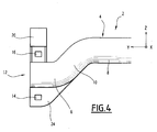
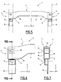
figure 4 is a view similar to that of thefigure 2 illustrating a variant of the embodiment of theFigures 1 to 3 ; - the
Figures 5 to 7 will be views similar to those ofFigures 1 to 3 of an alternative embodiment.
La traverse 2 de planche de bord de véhicule automobile de la
Dans la suite de la description, en l'absence de précision, les termes « longitudinal », « transversal », « vertical », « horizontal », « haut » et « bas » s'entendent pas référence au système d'axes orthogonal usuel des véhicules automobiles, illustré sur les figures et comprenant :
- un axe longitudinal X-X, horizontal et orienté de l'arrière vers l'avant ;
- un axe transversal Y-Y, horizontal et orienté de la droite vers la gauche ; et
- un axe vertical Z-Z, orienté du bas vers le haut.
- a longitudinal axis XX, horizontal and oriented from the rear to the front;
- a transverse axis YY, horizontal and oriented from right to left; and
- a vertical axis ZZ, oriented from bottom to top.
La traverse 2 a notamment pour fonctions de rigidifier la structure du véhicule automobile et de supporter des équipements fonctionnels du véhicule automobile tels qu'une colonne de direction, un système de ventilation de chauffage et de climatisation (système HVAC), un autoradio, un système GPS, un module d'airbag passager, une boîte à gants, etc....The
La traverse 2 comprend une poutre 4 tubulaire métallique réalisée d'un seul tenant s'étendant sensiblement suivant l'axe transversal Y-Y. La poutre 4 comprend deux tronçons d'extrémité 6 et un tronçon central 8 s'étendant entre les tronçons d'extrémité 6. Chaque tronçon d'extrémité 6 est prévu pour être relié à un montant A respectif.The
Chaque tronçon d'extrémité 6 est relié au tronçon central 8 par un décrochement 10 vers le bas de sorte que chaque tronçon d'extrémité 6 est décalé vers le bas par rapport au tronçon central 8.Each
Le tronçon central 8 est tubulaire et de section droite constante, par exemple de section circulaire. Il s'étend de manière rectiligne suivant l'axe transversal Y-Y. En variante, le tronçon central 8 peut s'étendre suivant une ligne courbe en présentant par exemple des portions de longueur rectilignes reliées par des décrochements, et/ou une section droite variable.The
Les tronçons d'extrémité 6 sont tubulaires de section droite constante et s'étendent de manière rectiligne suivant l'axe transversal Y-Y. Ils sont désaxés suivant l'axe vertical Z-Z vers le bas par rapport au tronçon central 6.The
Chaque tronçon d'extrémité 6 est prévu pour être fixé à un montant A respectif au moyen d'éléments de fixation s'étendant sensiblement suivant l'axe longitudinal X-X. A cet effet, la traverse 2 comprend des moyens de fixation 12 pour la fixation de chaque tronçon d'extrémité 6 sur la structure du véhicule.Each
Les moyens de fixation 12 de chaque tronçon d'extrémité 6 comprennent un premier orifice 14 et un deuxième orifice 16 de fixation du tronçon d'extrémité 6 suivant l'axe longitudinal X-X. Le premier orifice 14 et le deuxième orifice 16 sont espacés suivant l'axe vertical Z-Z et sont chacun prévu pour le passage d'un élément de fixation du type vis, boulon ou rivet, sensiblement suivant l'axe longitudinal X-X. Des éléments de fixation sont symbolisés par des traits mixtes référencés 18 sur la
Selon l'invention, le premier orifice 14 des moyens de fixation 12 de chaque tronçon d'extrémité 6 est ménagé au travers de la poutre 4 et les moyens de fixation 12 comprennent en outre un organe de fixation 20 rapporté sur le tronçon d'extrémité 6, le deuxième orifice 16 étant ménagé au travers de l'organe de fixation 20.According to the invention, the
Dans le mode de réalisation des
L'organe de fixation 20 est fixé sous le tronçon d'extrémité 6 de façon qu'il fait saillie vers le bas à partir du tronçon d'extrémité 6. L'organe de fixation 20 et la platine 24 encadrent le tronçon d'extrémité 6. Ainsi, le premier orifice 14 et le deuxième orifice 16 encadrent le tronçon d'extrémité 6. De préférence, ils sont disposés symétriquement de part et d'autre du tronçon d'extrémité 6.The
Tel que représenté sur la
Plus spécifiquement, chaque tronçon d'extrémité 6 présente une section droite sensiblement semi-circulaire définie par une première paroi 26 en arc de cercle et une deuxième paroi 28 sensiblement plane s'étendant suivant la corde de l'arc de cercle. La platine 24 est formée par une troisième paroi 30 prolongeant la deuxième paroi 28 vers l'extérieur et une quatrième paroi 32 revenant vers et se raccordant sur la première paroi 26. Ainsi, la platine 24 est formée de deux épaisseurs et le premier orifice 14 est formé au travers des deux épaisseurs.More specifically, each
Tel que représenté sur la
L'entraxe E vertical entre le premier orifice 12 et le deuxième orifice 14 est prévu suffisamment grand pour une fixation rigide du tronçon d'extrémité 6 sur le montant A correspondant.The vertical spacing E between the
La poutre 2 monobloc est obtenue par un procédé d'hydroformage connu en soi dans lequel, une ébauche tubulaire est disposée dans une cavité de formage et un fluide sous pression tel que de l'eau ou de l'huile est injecté à l'intérieur de l'ébauche pour la déformer vers l'extérieur jusqu'à venir l'appliquer contre la paroi de la cavité de formage, présentant la forme extérieure souhaitée pour la poutre 2. Le procédé d'hydroformage peut constituer une première étape visant à former des ébauches de platine, qui sont ensuite écrasées pour obtenir la forme illustrée sur la
Chaque organe de fixation 20 est fixé sur le tronçon d'extrémité 6 correspondant par tout moyen approprié, et par exemple par soudage.Each
La combinaison d'une seule platine venue de matière avec la poutre et d'un organe de fixation rapporté sur la poutre pour la fixation d'un ou de chaque tronçon d'extrémité permet d'obtenir une poutre rigide et une fixation rigide de la poutre. Le tronçon d'extrémité peut être prévu avec un décalage vertical important par rapport au tronçon central en conservant une inertie importante et en obtenant un entraxe entre les premier et deuxième orifices de fixation suffisant grâce à l'organe de fixation additionnel rapporté sur le tronçon d'extrémité. La traverse peut en outre être obtenue à faible coût et avec un nombre d'opérations d'assemblage limité sur fait qu'un seul organe de fixation rapporté est nécessaire.The combination of a single plate made of material with the beam and a fastener attached to the beam for fixing one or each end section makes it possible to obtain a rigid beam and a rigid attachment of the beam. beam. The end section may be provided with a large vertical offset relative to the central section while maintaining a high inertia and obtaining a distance between the first and second fixing holes sufficient thanks to the additional fastener attached to the section d 'end. The crossbar can also be obtained at low cost and with a limited number of assembly operations on the fact that a single attachment member reported is necessary.
Telle que représenté sur les
Dans une variante illustrée sur la
La traverse 2 de planche de bord représentée sur les
L'organe de fixation 20 est fixé sur le dessus du tronçon d'extrémité 6.The fixing
Dans l'exemple illustré, chaque tronçon d'extrémité 6 présente une section droite quadrangulaire (
Chaque tronçon d'extrémité 6 est relié au tronçon central 8 par un tronçon de transition 38 de section droite variant façon monotone depuis la section droite du tronçon central 8, par exemple circulaire, jusqu'à la section droite du tronçon d'extrémité, par exemple quadrangulaire.Each
Dans l'exemple illustré, chaque tronçon d'extrémité 6 s'étend transversalement en étant décalé vers le bas par rapport au tronçon central 8. Chaque tronçon de transition 38 s'élargi progressivement vers le bas.In the illustrated example, each
Cette poutre peut être obtenue par hydroformage, ou par emboutissage par étapes successives à partir d'une ébauche tubulaire présentant la section transversale du tronçon central, les tronçons d'extrémité étant déformés par étape successives au cours desquelles on introduit un support interne dans les tronçons d'extrémité et on applique des matrices sur la surface extérieure des tronçons d'extrémités jusqu'à leur conférer la section droite voulue.This beam can be obtained by hydroforming, or by stamping in successive steps from a tubular blank having the cross section of the central section, the end sections being deformed in successive steps during which an internal support is introduced into the sections end and applies matrices on the outer surface of the end sections until they give the desired cross section.
Tel que représenté sur la
Dans l'exemple illustré, l'organe de renfort 40 se présente sous la forme d'un élément tubulaire s'étendant transversalement entre les deux faces verticales 36 en regard du premier orifice 14 de sorte que l'axe du premier orifice 14 s'étend au travers de l'organe de renfort 40.In the illustrated example, the reinforcing
La traverse du mode de réalisation des
L'invention n'est pas limitée à ces modes de réalisation, d'autres variantes étant envisageables.The invention is not limited to these embodiments, other variants being conceivable.
Notamment, dans les modes de réalisation illustrés, chaque tronçon d'extrémité chacun est fixé par l'intermédiaire d'un premier orifice prévu au travers de la poutre et d'un deuxième orifice prévu dans un organe de fixation rapporté sur le tronçon d'extrémité. En variante, un seul des deux tronçons d'extrémité est fixé de cette manière.In particular, in the illustrated embodiments, each end section each is fixed via a first orifice provided through the beam and a second orifice provided in a fastener attached to the section of the beam. end. As a variant, only one of the two end sections is fixed in this way.
Claims (10)
- A motor vehicle dashboard crossbeam, of the type comprising a tubular beam (4) made in a single piece provided to extend between the A posts of the structure of the motor vehicle substantially in a transverse direction (Y) of the motor vehicle and means (12) for fastening a or each end section (6) of the beam (4) on an A post, the fastening means (12) comprising a first (14) and second (16) fastening opening in the longitudinal direction (X), the first opening (14) being formed through the beam (4), characterized in that the fastening means also comprise a fastening member (20) attached on the or each end section (6), the second fastening opening (16) being formed through the fastening member (20).
- The crossbeam according to claim 1, wherein the beam (4) comprises a fastening platen (24) formed in a single piece with the or each end section (6) and protruding outward from the or each end section (6), the first opening (14) being formed through the platen (24).
- The crossbeam according to claim 2, wherein the fastening member (20) is attached on the or each end section such that the first opening (14) and the second opening (16) are positioned on either side of the end section (6).
- The crossbeam according to claim 2 or 3, wherein the first opening (14) and the second opening (16) are arranged symmetrically on either side of the or each end section (6).
- The crossbeam according to any one of claims 2 to 4, wherein the or each platen (24) gives the beam (4) a substantially P-shaped or upside down P-shaped cross-section at the or each end section.
- The crossbeam according to any one of the preceding claims, wherein the first opening (16) is formed through two opposite surfaces spaced apart from the end section (6).
- The crossbeam according to claim 6, comprising a reinforcing member inserted into the end section (6) between the two opposite surfaces to keep them spaced apart.
- The crossbeam according to any one of the preceding claims, wherein the beam (4) comprises a central section, the or each end section being offset relative to the central section and connected thereto by a recess (10).
- The crossbeam according to claim 8, wherein the central section is rectilinear.
- A motor vehicle comprising a dashboard crossbeam according to any one of the preceding claims.
Priority Applications (2)
| Application Number | Priority Date | Filing Date | Title |
|---|---|---|---|
| DE11712962.7T DE11712962T1 (en) | 2010-03-05 | 2011-03-03 | Cross member for the dashboard of a motor vehicle |
| PL11712962T PL2542462T3 (en) | 2010-03-05 | 2011-03-03 | Motor vehicle dashboard crossmember |
Applications Claiming Priority (2)
| Application Number | Priority Date | Filing Date | Title |
|---|---|---|---|
| FR1051621A FR2957046B1 (en) | 2010-03-05 | 2010-03-05 | AUTOMOTIVE VEHICLE BOARD TRAVERSE. |
| PCT/FR2011/050448 WO2011107716A1 (en) | 2010-03-05 | 2011-03-03 | Motor vehicle dashboard crossmember |
Publications (2)
| Publication Number | Publication Date |
|---|---|
| EP2542462A1 EP2542462A1 (en) | 2013-01-09 |
| EP2542462B1 true EP2542462B1 (en) | 2014-05-07 |
Family
ID=42338246
Family Applications (1)
| Application Number | Title | Priority Date | Filing Date |
|---|---|---|---|
| EP11712962.7A Active EP2542462B1 (en) | 2010-03-05 | 2011-03-03 | Motor vehicle dashboard crossmember |
Country Status (7)
| Country | Link |
|---|---|
| US (4) | US9333988B2 (en) |
| EP (1) | EP2542462B1 (en) |
| DE (2) | DE202011110441U1 (en) |
| ES (1) | ES2431240T3 (en) |
| FR (1) | FR2957046B1 (en) |
| PL (1) | PL2542462T3 (en) |
| WO (1) | WO2011107716A1 (en) |
Cited By (1)
| Publication number | Priority date | Publication date | Assignee | Title |
|---|---|---|---|---|
| EP3786032A1 (en) | 2020-11-11 | 2021-03-03 | Benteler Automobiltechnik GmbH | Instrument panel holder for a motor vehicle |
Families Citing this family (10)
| Publication number | Priority date | Publication date | Assignee | Title |
|---|---|---|---|---|
| FR2957046B1 (en) | 2010-03-05 | 2012-05-11 | Faurecia Interieur Ind | AUTOMOTIVE VEHICLE BOARD TRAVERSE. |
| DE102013107156B4 (en) | 2013-07-08 | 2019-02-14 | Wago Verwaltungsgesellschaft Mbh | PCB connector |
| DE102015101393A1 (en) * | 2015-01-30 | 2016-08-04 | Kirchhoff Automotive Deutschland Gmbh | Module carrier assembly for a motor vehicle |
| FR3043050B1 (en) * | 2015-10-29 | 2017-11-24 | Faurecia Interieur Ind | VEHICLE TRAVERSE |
| US10457240B2 (en) * | 2016-11-04 | 2019-10-29 | Magnesium Products Of America | Glove box rail with integrated airbag support |
| CN108146335A (en) * | 2017-12-28 | 2018-06-12 | 天津沃尔德泰克机电有限公司 | A kind of vehicle beam stent |
| DE102019213301B4 (en) * | 2019-09-03 | 2022-09-08 | Audi Ag | Method of assembling a cross member or longitudinal member in a motor vehicle |
| DE102019131425A1 (en) * | 2019-11-21 | 2021-05-27 | Kirchhoff Automotive Deutschland Gmbh | Instrument panel carrier |
| CN114379657B (en) * | 2022-01-25 | 2023-03-28 | 东风汽车集团股份有限公司 | Passenger car instrument desk crossbeam and car |
| DE102022101980B3 (en) | 2022-01-28 | 2023-05-17 | Audi Aktiengesellschaft | Vehicle structural component made of wood and manufacturing method |
Family Cites Families (45)
| Publication number | Priority date | Publication date | Assignee | Title |
|---|---|---|---|---|
| SE406303B (en) | 1977-12-12 | 1979-02-05 | Saab Scania Ab | ARRANGEMENTS AT STEERING INSTALLATIONS IN MOTOR VEHICLES |
| FR2487262A1 (en) * | 1980-07-22 | 1982-01-29 | Fiat Auto Spa | REAR AXLE FOR MOTOR VEHICLE |
| DE4134436C2 (en) | 1990-10-29 | 1999-07-08 | Volkswagen Ag | Motor vehicle body with a front wall cross member extending between A-pillars |
| US5282637A (en) * | 1991-12-13 | 1994-02-01 | Ford Motor Company | Mount for vehicle front support structure |
| US5868426A (en) * | 1997-05-27 | 1999-02-09 | Chrysler Corporation | Cross car steering column support and method of installation |
| DE19735089A1 (en) | 1997-08-13 | 1999-02-18 | Erbsloeh Ag | Cross member for holding the steering column of a motor vehicle, in particular a passenger car |
| US6176544B1 (en) * | 1997-12-19 | 2001-01-23 | Alcoa Inc. | Instrument panel reinforcement structure including a novel driver side cross tube |
| US5931520A (en) | 1997-12-19 | 1999-08-03 | Aluminum Company Of America | Light weight instrument panel reinforcement structure |
| DE19830303B4 (en) | 1998-07-07 | 2006-07-06 | Volkswagen Ag | Arrangement of an instrument panel carrier in a vehicle body and instrument panel carrier |
| FR2783489B1 (en) * | 1998-09-21 | 2000-12-08 | Vallourec Vitry | HOLLOW SUPPORT STRUCTURE OF ELONGATE FORM COMPRISING A TRANSVERSE FLANGE AT EACH OF ITS END |
| DE19845146A1 (en) * | 1998-10-01 | 2000-04-13 | Progress Werk Oberkirch Ag | Method for producing a cross member and such cross members |
| FR2790435B1 (en) | 1999-03-05 | 2001-05-25 | Ecia Equip Composants Ind Auto | ARRANGEMENT OF A STEERING COLUMN IN A MOTOR VEHICLE INTERIOR |
| DE19926636A1 (en) * | 1999-06-11 | 2000-12-14 | Porsche Ag | Cockpit cross member in a motor vehicle |
| EP1193161A4 (en) | 2000-01-24 | 2003-06-04 | Futaba Kogyo Co Ltd | Structure of instrument panel support member |
| DE10101927B4 (en) | 2001-01-16 | 2006-05-24 | Wagon Automotive Gmbh | Structural component of a motor vehicle body and method for producing such a structural component |
| DE10104790B4 (en) * | 2001-02-02 | 2005-11-24 | Dr.Ing.H.C. F. Porsche Ag | Cross member for a dashboard of a vehicle |
| DE10221654B4 (en) | 2001-10-01 | 2005-10-13 | Dura Automotive Plettenberg Entwicklungs- Und Vertriebs Gmbh | Cross member for a motor vehicle |
| MXPA04003386A (en) | 2001-10-11 | 2004-06-18 | Collins & Aikman Automotive Co | Integrated steel cross-car beam. |
| US7128360B2 (en) * | 2002-12-10 | 2006-10-31 | Delphi Technologies, Inc. | Structural hybrid attachment system and method |
| US6921128B2 (en) * | 2003-05-06 | 2005-07-26 | Lear Corporation | Universal energy absorbing bracket |
| DE10323999B4 (en) * | 2003-05-27 | 2005-09-22 | Dr.Ing.H.C. F. Porsche Ag | Fastening arrangement for a cockpit module of a motor vehicle |
| FR2859446B1 (en) | 2003-09-09 | 2007-09-07 | Faurecia Interieur Ind | TRAVERSE FOR MOTOR VEHICLE COMPRISING A REINFORCED STRING. |
| FR2861682B1 (en) | 2003-11-04 | 2006-02-24 | Renault Sas | VEHICLE STRUCTURE TUBE |
| US7407221B2 (en) * | 2003-11-24 | 2008-08-05 | L&W Engineering Incorporated | Support structures using tubes having variable wall thicknesses |
| DE102004013384A1 (en) | 2004-03-17 | 2005-10-06 | Behr Gmbh & Co. Kg | Cross member or structural component for a motor vehicle |
| FR2874581B1 (en) | 2004-08-30 | 2007-11-23 | Wagon Automotive S A Sa | DASHBOARD TRAVERSE |
| EP1647469A1 (en) | 2004-10-12 | 2006-04-19 | Alcan Technology & Management Ltd. | Instrument panel support structure of a motor vehicle |
| US7048325B1 (en) * | 2004-10-21 | 2006-05-23 | Chain Singh Sandhu | Adjustable vehicle cross beam |
| US7216927B2 (en) | 2004-12-03 | 2007-05-15 | Gm Global Technology Operations, Inc. | Lightweight hybrid tubular/casting instrument panel beam |
| DE102005004605B4 (en) | 2005-02-01 | 2009-03-05 | Lisa Dräxlmaier GmbH | Crossmember module for a motor vehicle |
| FR2881393B1 (en) * | 2005-02-03 | 2008-10-17 | Faurecia Interieur Ind Snc | MOTOR VEHICLE DASHBOARD TRAVERSE, ASSEMBLY COMPRISING SUCH A TRAVERSE, AND METHOD OF MANUFACTURING SUCH A TRAVERSE |
| DE102006005023A1 (en) | 2005-03-31 | 2006-10-05 | Linde + Wiemann Gmbh Kg | Dashboard carrier for motor vehicle, has intake area whose lower part forms intake section that lies against hollow section, where intake section is designed as extension of side wall of hollow section |
| FR2884215B1 (en) * | 2005-04-06 | 2007-07-20 | Faurecia Interieur Ind Snc | REINFORCING STRUCTURE FOR A MOTOR VEHICLE CAPABLE OF LIMITING THE DASHBOARD VIBRATIONS AND THE CORRESPONDING MOTOR VEHICLE. |
| JP4119919B2 (en) | 2006-01-27 | 2008-07-16 | 株式会社アステア | Steering column bracket |
| DE102006020947A1 (en) | 2006-05-05 | 2007-11-08 | Dr.Ing.H.C. F. Porsche Ag | Cross member arrangement for a motor vehicle |
| FR2901529B1 (en) * | 2006-05-24 | 2008-10-31 | Faurecia Interieur Ind Snc | AUTOMOTIVE VEHICLE BOARD TRAVERSE |
| EP1882623B1 (en) | 2006-07-25 | 2010-11-03 | NSK Ltd. | Electric Power steering apparatus |
| DE102006055506A1 (en) | 2006-11-24 | 2008-05-29 | Dr.Ing.H.C. F. Porsche Ag | Cross member, in particular a cockpit cross member |
| FR2925009B1 (en) | 2007-12-14 | 2010-03-12 | Faurecia Interieur Ind | BEAM FOR DASHBOARD OF MOTOR VEHICLE |
| FR2926526B1 (en) | 2008-01-22 | 2010-06-04 | Faurecia Interieur Ind | MOTOR VEHICLE TRAVERSE, DASHBOARD AND MANUFACTURING METHOD THEREOF |
| DE102008026138A1 (en) | 2008-04-24 | 2009-10-29 | Dura Automotive Body & Glass Systems Gmbh | Cockpit cross member for a motor vehicle |
| FR2957046B1 (en) | 2010-03-05 | 2012-05-11 | Faurecia Interieur Ind | AUTOMOTIVE VEHICLE BOARD TRAVERSE. |
| JP5508109B2 (en) * | 2010-04-16 | 2014-05-28 | 株式会社アステア | Steering support frame |
| FR2991650B1 (en) * | 2012-06-07 | 2014-06-20 | Peugeot Citroen Automobiles Sa | VEHICLE DASHBOARD TRAILER HAVING FIBER COMPOSITE DORSAL REINFORCING SPACER |
| US9446800B2 (en) * | 2014-05-30 | 2016-09-20 | Van-Rob Inc. | Vehicle cross-support member with hybrid metal joint |
-
2010
- 2010-03-05 FR FR1051621A patent/FR2957046B1/en not_active Expired - Fee Related
-
2011
- 2011-03-03 DE DE202011110441.2U patent/DE202011110441U1/en not_active Expired - Lifetime
- 2011-03-03 WO PCT/FR2011/050448 patent/WO2011107716A1/en active Application Filing
- 2011-03-03 EP EP11712962.7A patent/EP2542462B1/en active Active
- 2011-03-03 ES ES11712962.7T patent/ES2431240T3/en active Active
- 2011-03-03 PL PL11712962T patent/PL2542462T3/en unknown
- 2011-03-03 US US13/807,073 patent/US9333988B2/en active Active
- 2011-03-03 DE DE11712962.7T patent/DE11712962T1/en active Pending
-
2016
- 2016-03-24 US US15/080,066 patent/US10232892B2/en active Active
-
2019
- 2019-02-11 US US16/272,567 patent/US10696333B2/en active Active
-
2020
- 2020-04-07 US US16/842,348 patent/US11242095B2/en active Active
Cited By (3)
| Publication number | Priority date | Publication date | Assignee | Title |
|---|---|---|---|---|
| EP3786032A1 (en) | 2020-11-11 | 2021-03-03 | Benteler Automobiltechnik GmbH | Instrument panel holder for a motor vehicle |
| EP4001065A1 (en) | 2020-11-11 | 2022-05-25 | Benteler Automobiltechnik GmbH | Instrument panel holder for a motor vehicle |
| EP4122803A1 (en) | 2020-11-11 | 2023-01-25 | Volkswagen AG | Instrument panel holder for a motor vehicle |
Also Published As
| Publication number | Publication date |
|---|---|
| PL2542462T3 (en) | 2014-10-31 |
| US20160200367A1 (en) | 2016-07-14 |
| WO2011107716A1 (en) | 2011-09-09 |
| US20190168824A1 (en) | 2019-06-06 |
| DE11712962T1 (en) | 2014-01-23 |
| DE202011110441U1 (en) | 2014-01-28 |
| ES2431240T3 (en) | 2014-08-07 |
| US11242095B2 (en) | 2022-02-08 |
| US20140327270A1 (en) | 2014-11-06 |
| ES2431240T1 (en) | 2013-11-25 |
| US10232892B2 (en) | 2019-03-19 |
| US20200231224A1 (en) | 2020-07-23 |
| US10696333B2 (en) | 2020-06-30 |
| EP2542462A1 (en) | 2013-01-09 |
| FR2957046B1 (en) | 2012-05-11 |
| FR2957046A1 (en) | 2011-09-09 |
| US9333988B2 (en) | 2016-05-10 |
Similar Documents
| Publication | Publication Date | Title |
|---|---|---|
| EP2542462B1 (en) | Motor vehicle dashboard crossmember | |
| WO2006106230A1 (en) | Structural element for a motor vehicle, corresponding motor vehicle, and method for producing one such structural element | |
| EP2499038B1 (en) | Motor vehicle dashboard structure and motor vehicle including such a structure | |
| EP2436579B1 (en) | Dashboard crossmember unit for an automobile. | |
| EP2009298B1 (en) | Screwing support, in particular for an automobile seat element, and method for assembling such a support | |
| WO2011015763A1 (en) | Dashboard module for a motor vehicle, and motor vehicle provided with such a module | |
| EP2342120A1 (en) | Dashboard crossbar assembly for an automobile, and corresponding dashboard device, vehicle, and manufacturing method | |
| FR2900896A1 (en) | LIAISON COMPONENT FOR CARRYING OUT A LONGERON, LONGERON COMPRISING SUCH AN ELEMENT AND MOTOR VEHICLE COMPRISING AT LEAST ONE SUCH LONGERON | |
| EP3405382B1 (en) | Part for reinforcing a lower crossbeam for a window opening | |
| EP2763885B1 (en) | Motor vehicle dashboard crossmember arrangement and vehicle comprising such an arrangement | |
| EP2470412B1 (en) | Member for attaching a dashboard crossbeam onto a structural member, in particular for a motor vehicle | |
| EP2066551B1 (en) | Motor vehicle front-end panel, series of front-end panels and assembly method | |
| EP2300271A1 (en) | Motor vehicle body comprising a soundproofing element and motor vehicle comprising such a body | |
| EP3375697B1 (en) | A-pillar provided with a mounting for securing a motor vehicle dashboard crossbar | |
| EP3863912B1 (en) | Seat floor structure reinforced in case of pole impact | |
| FR3062367B1 (en) | DASHBOARD TRAVERSE AND MODULAR STEERING COLUMN SUPPORT CONSOLE | |
| FR3122134A1 (en) | FRONT BUMPER FRAME WITH CENTRAL PILLAR | |
| EP2490917B1 (en) | Automobile dashboard cross-member | |
| EP3209538B1 (en) | Crossmember intended for contributing to the soundproofing of a motor vehicle | |
| FR3058375A1 (en) | MODULAR DASHBOARD AIRBAG FASTENING | |
| EP3880540A1 (en) | Modular a-pillar reinforcement | |
| EP3865339A1 (en) | System for installing at least one rear seat in a lorry cab, lorry cab comprising such a system and method for installing such a system in a lorry cab | |
| FR3107016A1 (en) | UNIVERSAL SUPPORT FOR FIXING A MOTOR VEHICLE SEAT | |
| FR2925455A1 (en) | Fascia for motor vehicle, has MacPherson strut including upper end fixed to central part of cross-piece, and lower end with fixation zone fixed on structural element, where lower end has reinforcement zone folded against fixation zone | |
| FR2906775A1 (en) | Motor vehicle assembly e.g. fascia assembly, has fixation unit with connection arms, junction element with opposite ends integrated with ends of connection arms, and air bag device supported against arms and junction element |
Legal Events
| Date | Code | Title | Description |
|---|---|---|---|
| PUAI | Public reference made under article 153(3) epc to a published international application that has entered the european phase |
Free format text: ORIGINAL CODE: 0009012 |
|
| 17P | Request for examination filed |
Effective date: 20120831 |
|
| AK | Designated contracting states |
Kind code of ref document: A1 Designated state(s): AL AT BE BG CH CY CZ DE DK EE ES FI FR GB GR HR HU IE IS IT LI LT LU LV MC MK MT NL NO PL PT RO RS SE SI SK SM TR |
|
| DAX | Request for extension of the european patent (deleted) | ||
| GRAP | Despatch of communication of intention to grant a patent |
Free format text: ORIGINAL CODE: EPIDOSNIGR1 |
|
| INTG | Intention to grant announced |
Effective date: 20130920 |
|
| REG | Reference to a national code |
Ref country code: DE Ref legal event code: R210 Ref document number: 602011006817 Country of ref document: DE Effective date: 20140123 Ref country code: DE Ref legal event code: R210 Effective date: 20140123 |
|
| GRAS | Grant fee paid |
Free format text: ORIGINAL CODE: EPIDOSNIGR3 |
|
| GRAA | (expected) grant |
Free format text: ORIGINAL CODE: 0009210 |
|
| AK | Designated contracting states |
Kind code of ref document: B1 Designated state(s): AL AT BE BG CH CY CZ DE DK EE ES FI FR GB GR HR HU IE IS IT LI LT LU LV MC MK MT NL NO PL PT RO RS SE SI SK SM TR |
|
| REG | Reference to a national code |
Ref country code: GB Ref legal event code: FG4D Free format text: NOT ENGLISH |
|
| REG | Reference to a national code |
Ref country code: DE Ref legal event code: R082 Ref document number: 602011006817 Country of ref document: DE Representative=s name: LAVOIX MUNICH, DE Ref country code: DE Ref legal event code: R082 Ref document number: 602011006817 Country of ref document: DE |
|
| REG | Reference to a national code |
Ref country code: AT Ref legal event code: REF Ref document number: 666407 Country of ref document: AT Kind code of ref document: T Effective date: 20140515 |
|
| REG | Reference to a national code |
Ref country code: IE Ref legal event code: FG4D Free format text: LANGUAGE OF EP DOCUMENT: FRENCH |
|
| REG | Reference to a national code |
Ref country code: DE Ref legal event code: R096 Ref document number: 602011006817 Country of ref document: DE Effective date: 20140618 |
|
| REG | Reference to a national code |
Ref country code: ES Ref legal event code: FG2A Ref document number: 2431240 Country of ref document: ES Kind code of ref document: T3 Effective date: 20140807 |
|
| REG | Reference to a national code |
Ref country code: AT Ref legal event code: MK05 Ref document number: 666407 Country of ref document: AT Kind code of ref document: T Effective date: 20140507 |
|
| REG | Reference to a national code |
Ref country code: NL Ref legal event code: VDEP Effective date: 20140507 |
|
| REG | Reference to a national code |
Ref country code: LT Ref legal event code: MG4D |
|
| PG25 | Lapsed in a contracting state [announced via postgrant information from national office to epo] |
Ref country code: IS Free format text: LAPSE BECAUSE OF FAILURE TO SUBMIT A TRANSLATION OF THE DESCRIPTION OR TO PAY THE FEE WITHIN THE PRESCRIBED TIME-LIMIT Effective date: 20140907 Ref country code: GR Free format text: LAPSE BECAUSE OF FAILURE TO SUBMIT A TRANSLATION OF THE DESCRIPTION OR TO PAY THE FEE WITHIN THE PRESCRIBED TIME-LIMIT Effective date: 20140808 Ref country code: LT Free format text: LAPSE BECAUSE OF FAILURE TO SUBMIT A TRANSLATION OF THE DESCRIPTION OR TO PAY THE FEE WITHIN THE PRESCRIBED TIME-LIMIT Effective date: 20140507 Ref country code: NO Free format text: LAPSE BECAUSE OF FAILURE TO SUBMIT A TRANSLATION OF THE DESCRIPTION OR TO PAY THE FEE WITHIN THE PRESCRIBED TIME-LIMIT Effective date: 20140807 Ref country code: FI Free format text: LAPSE BECAUSE OF FAILURE TO SUBMIT A TRANSLATION OF THE DESCRIPTION OR TO PAY THE FEE WITHIN THE PRESCRIBED TIME-LIMIT Effective date: 20140507 Ref country code: CY Free format text: LAPSE BECAUSE OF FAILURE TO SUBMIT A TRANSLATION OF THE DESCRIPTION OR TO PAY THE FEE WITHIN THE PRESCRIBED TIME-LIMIT Effective date: 20140507 |
|
| REG | Reference to a national code |
Ref country code: PL Ref legal event code: T3 |
|
| PG25 | Lapsed in a contracting state [announced via postgrant information from national office to epo] |
Ref country code: SE Free format text: LAPSE BECAUSE OF FAILURE TO SUBMIT A TRANSLATION OF THE DESCRIPTION OR TO PAY THE FEE WITHIN THE PRESCRIBED TIME-LIMIT Effective date: 20140507 Ref country code: HR Free format text: LAPSE BECAUSE OF FAILURE TO SUBMIT A TRANSLATION OF THE DESCRIPTION OR TO PAY THE FEE WITHIN THE PRESCRIBED TIME-LIMIT Effective date: 20140507 Ref country code: RS Free format text: LAPSE BECAUSE OF FAILURE TO SUBMIT A TRANSLATION OF THE DESCRIPTION OR TO PAY THE FEE WITHIN THE PRESCRIBED TIME-LIMIT Effective date: 20140507 Ref country code: LV Free format text: LAPSE BECAUSE OF FAILURE TO SUBMIT A TRANSLATION OF THE DESCRIPTION OR TO PAY THE FEE WITHIN THE PRESCRIBED TIME-LIMIT Effective date: 20140507 Ref country code: AT Free format text: LAPSE BECAUSE OF FAILURE TO SUBMIT A TRANSLATION OF THE DESCRIPTION OR TO PAY THE FEE WITHIN THE PRESCRIBED TIME-LIMIT Effective date: 20140507 |
|
| PG25 | Lapsed in a contracting state [announced via postgrant information from national office to epo] |
Ref country code: PT Free format text: LAPSE BECAUSE OF FAILURE TO SUBMIT A TRANSLATION OF THE DESCRIPTION OR TO PAY THE FEE WITHIN THE PRESCRIBED TIME-LIMIT Effective date: 20140908 |
|
| REG | Reference to a national code |
Ref country code: HU Ref legal event code: AG4A Ref document number: E021516 Country of ref document: HU |
|
| PG25 | Lapsed in a contracting state [announced via postgrant information from national office to epo] |
Ref country code: RO Free format text: LAPSE BECAUSE OF FAILURE TO SUBMIT A TRANSLATION OF THE DESCRIPTION OR TO PAY THE FEE WITHIN THE PRESCRIBED TIME-LIMIT Effective date: 20140507 Ref country code: EE Free format text: LAPSE BECAUSE OF FAILURE TO SUBMIT A TRANSLATION OF THE DESCRIPTION OR TO PAY THE FEE WITHIN THE PRESCRIBED TIME-LIMIT Effective date: 20140507 Ref country code: DK Free format text: LAPSE BECAUSE OF FAILURE TO SUBMIT A TRANSLATION OF THE DESCRIPTION OR TO PAY THE FEE WITHIN THE PRESCRIBED TIME-LIMIT Effective date: 20140507 Ref country code: SK Free format text: LAPSE BECAUSE OF FAILURE TO SUBMIT A TRANSLATION OF THE DESCRIPTION OR TO PAY THE FEE WITHIN THE PRESCRIBED TIME-LIMIT Effective date: 20140507 |
|
| REG | Reference to a national code |
Ref country code: DE Ref legal event code: R097 Ref document number: 602011006817 Country of ref document: DE |
|
| PG25 | Lapsed in a contracting state [announced via postgrant information from national office to epo] |
Ref country code: NL Free format text: LAPSE BECAUSE OF FAILURE TO SUBMIT A TRANSLATION OF THE DESCRIPTION OR TO PAY THE FEE WITHIN THE PRESCRIBED TIME-LIMIT Effective date: 20140507 |
|
| PLBE | No opposition filed within time limit |
Free format text: ORIGINAL CODE: 0009261 |
|
| STAA | Information on the status of an ep patent application or granted ep patent |
Free format text: STATUS: NO OPPOSITION FILED WITHIN TIME LIMIT |
|
| 26N | No opposition filed |
Effective date: 20150210 |
|
| PG25 | Lapsed in a contracting state [announced via postgrant information from national office to epo] |
Ref country code: IT Free format text: LAPSE BECAUSE OF FAILURE TO SUBMIT A TRANSLATION OF THE DESCRIPTION OR TO PAY THE FEE WITHIN THE PRESCRIBED TIME-LIMIT Effective date: 20140507 |
|
| REG | Reference to a national code |
Ref country code: DE Ref legal event code: R097 Ref document number: 602011006817 Country of ref document: DE Effective date: 20150210 |
|
| PG25 | Lapsed in a contracting state [announced via postgrant information from national office to epo] |
Ref country code: SI Free format text: LAPSE BECAUSE OF FAILURE TO SUBMIT A TRANSLATION OF THE DESCRIPTION OR TO PAY THE FEE WITHIN THE PRESCRIBED TIME-LIMIT Effective date: 20140507 |
|
| PG25 | Lapsed in a contracting state [announced via postgrant information from national office to epo] |
Ref country code: LU Free format text: LAPSE BECAUSE OF FAILURE TO SUBMIT A TRANSLATION OF THE DESCRIPTION OR TO PAY THE FEE WITHIN THE PRESCRIBED TIME-LIMIT Effective date: 20150303 Ref country code: MC Free format text: LAPSE BECAUSE OF FAILURE TO SUBMIT A TRANSLATION OF THE DESCRIPTION OR TO PAY THE FEE WITHIN THE PRESCRIBED TIME-LIMIT Effective date: 20140507 |
|
| REG | Reference to a national code |
Ref country code: CH Ref legal event code: PL |
|
| GBPC | Gb: european patent ceased through non-payment of renewal fee |
Effective date: 20150303 |
|
| REG | Reference to a national code |
Ref country code: IE Ref legal event code: MM4A |
|
| PG25 | Lapsed in a contracting state [announced via postgrant information from national office to epo] |
Ref country code: GB Free format text: LAPSE BECAUSE OF NON-PAYMENT OF DUE FEES Effective date: 20150303 Ref country code: LI Free format text: LAPSE BECAUSE OF NON-PAYMENT OF DUE FEES Effective date: 20150331 Ref country code: IE Free format text: LAPSE BECAUSE OF NON-PAYMENT OF DUE FEES Effective date: 20150303 Ref country code: CH Free format text: LAPSE BECAUSE OF NON-PAYMENT OF DUE FEES Effective date: 20150331 |
|
| REG | Reference to a national code |
Ref country code: FR Ref legal event code: PLFP Year of fee payment: 6 |
|
| PG25 | Lapsed in a contracting state [announced via postgrant information from national office to epo] |
Ref country code: MT Free format text: LAPSE BECAUSE OF FAILURE TO SUBMIT A TRANSLATION OF THE DESCRIPTION OR TO PAY THE FEE WITHIN THE PRESCRIBED TIME-LIMIT Effective date: 20140507 |
|
| REG | Reference to a national code |
Ref country code: FR Ref legal event code: PLFP Year of fee payment: 7 |
|
| PG25 | Lapsed in a contracting state [announced via postgrant information from national office to epo] |
Ref country code: BG Free format text: LAPSE BECAUSE OF FAILURE TO SUBMIT A TRANSLATION OF THE DESCRIPTION OR TO PAY THE FEE WITHIN THE PRESCRIBED TIME-LIMIT Effective date: 20140507 Ref country code: SM Free format text: LAPSE BECAUSE OF FAILURE TO SUBMIT A TRANSLATION OF THE DESCRIPTION OR TO PAY THE FEE WITHIN THE PRESCRIBED TIME-LIMIT Effective date: 20140507 |
|
| PG25 | Lapsed in a contracting state [announced via postgrant information from national office to epo] |
Ref country code: BE Free format text: LAPSE BECAUSE OF NON-PAYMENT OF DUE FEES Effective date: 20150331 |
|
| PG25 | Lapsed in a contracting state [announced via postgrant information from national office to epo] |
Ref country code: TR Free format text: LAPSE BECAUSE OF FAILURE TO SUBMIT A TRANSLATION OF THE DESCRIPTION OR TO PAY THE FEE WITHIN THE PRESCRIBED TIME-LIMIT Effective date: 20140507 |
|
| REG | Reference to a national code |
Ref country code: FR Ref legal event code: PLFP Year of fee payment: 8 |
|
| PG25 | Lapsed in a contracting state [announced via postgrant information from national office to epo] |
Ref country code: MK Free format text: LAPSE BECAUSE OF FAILURE TO SUBMIT A TRANSLATION OF THE DESCRIPTION OR TO PAY THE FEE WITHIN THE PRESCRIBED TIME-LIMIT Effective date: 20140507 |
|
| PG25 | Lapsed in a contracting state [announced via postgrant information from national office to epo] |
Ref country code: AL Free format text: LAPSE BECAUSE OF FAILURE TO SUBMIT A TRANSLATION OF THE DESCRIPTION OR TO PAY THE FEE WITHIN THE PRESCRIBED TIME-LIMIT Effective date: 20140507 |
|
| REG | Reference to a national code |
Ref country code: DE Ref legal event code: R008 Ref document number: 602011006817 Country of ref document: DE Ref country code: DE Ref legal event code: R039 Ref document number: 602011006817 Country of ref document: DE |
|
| REG | Reference to a national code |
Ref country code: DE Ref legal event code: R040 Ref document number: 602011006817 Country of ref document: DE |
|
| PGFP | Annual fee paid to national office [announced via postgrant information from national office to epo] |
Ref country code: FR Payment date: 20230222 Year of fee payment: 13 Ref country code: CZ Payment date: 20230224 Year of fee payment: 13 |
|
| PGFP | Annual fee paid to national office [announced via postgrant information from national office to epo] |
Ref country code: PL Payment date: 20230224 Year of fee payment: 13 Ref country code: HU Payment date: 20230301 Year of fee payment: 13 Ref country code: DE Payment date: 20230221 Year of fee payment: 13 |
|
| PGFP | Annual fee paid to national office [announced via postgrant information from national office to epo] |
Ref country code: ES Payment date: 20230403 Year of fee payment: 13 |