EP2499038B1 - Motor vehicle dashboard structure and motor vehicle including such a structure - Google Patents
Motor vehicle dashboard structure and motor vehicle including such a structure Download PDFInfo
- Publication number
- EP2499038B1 EP2499038B1 EP10792986.1A EP10792986A EP2499038B1 EP 2499038 B1 EP2499038 B1 EP 2499038B1 EP 10792986 A EP10792986 A EP 10792986A EP 2499038 B1 EP2499038 B1 EP 2499038B1
- Authority
- EP
- European Patent Office
- Prior art keywords
- cross
- section
- structure according
- end portion
- fixing
- Prior art date
- Legal status (The legal status is an assumption and is not a legal conclusion. Google has not performed a legal analysis and makes no representation as to the accuracy of the status listed.)
- Active
Links
- 239000002184 metal Substances 0.000 claims description 5
- 230000002787 reinforcement Effects 0.000 claims 2
- 230000003014 reinforcing effect Effects 0.000 description 7
- 238000007493 shaping process Methods 0.000 description 3
- 230000007704 transition Effects 0.000 description 3
- 238000004519 manufacturing process Methods 0.000 description 2
- 238000000034 method Methods 0.000 description 2
- 238000009423 ventilation Methods 0.000 description 2
- 238000004378 air conditioning Methods 0.000 description 1
- 230000000712 assembly Effects 0.000 description 1
- 238000000429 assembly Methods 0.000 description 1
- 239000012530 fluid Substances 0.000 description 1
- 238000010438 heat treatment Methods 0.000 description 1
- 230000001788 irregular Effects 0.000 description 1
- 239000000463 material Substances 0.000 description 1
- 238000003466 welding Methods 0.000 description 1
Images


Classifications
-
- B—PERFORMING OPERATIONS; TRANSPORTING
- B62—LAND VEHICLES FOR TRAVELLING OTHERWISE THAN ON RAILS
- B62D—MOTOR VEHICLES; TRAILERS
- B62D25/00—Superstructure or monocoque structure sub-units; Parts or details thereof not otherwise provided for
- B62D25/08—Front or rear portions
- B62D25/14—Dashboards as superstructure sub-units
- B62D25/145—Dashboards as superstructure sub-units having a crossbeam incorporated therein
Definitions
- the present invention relates to a dashboard structure of a motor vehicle, of the type comprising a dashboard crossmember intended to extend transversely between two lateral uprights of a motor vehicle body, and elements for fixing the ends of the vehicle. crosses to the lateral uprights, each fastening element comprising at least one fixing hole for the passage of an elongate fastener.
- the dashboard structures are intended to stiffen the body of the motor vehicle and to support motor vehicle equipment, including a steering column, a ventilation system for heating and / or air conditioning of the passenger compartment, a dashboard or a glove box.
- dashboard crossbar intended to be arranged transversely between the front lateral uprights of the body of a motor vehicle, generally called "A-pillars", and fastening elements of the dashboard crossmember on the uprights.
- A-pillars generally comprise a dashboard crossbar intended to be arranged transversely between the front lateral uprights of the body of a motor vehicle, generally called "A-pillars", and fastening elements of the dashboard crossmember on the uprights.
- lateral see for example FR 2,859,446 , FR 2 861 682 , FR 2,874,581 and US 2007/0175375 ).
- An object of the present invention is to provide a motor vehicle dashboard structure that is resistant and low manufacturing cost.
- the invention proposes a dashboard structure of the aforementioned type, characterized in that the cross member comprises at least one tubular section made in one piece and comprising a running portion extending between the ends of the cross member. and a cross-member end portion defining a fastener member of the cross member on the side post.
- the invention also relates to a motor vehicle having a body and a dashboard structure as defined above.
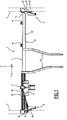
- the structure 2 of the motor vehicle dashboard comprises a dashboard crosspiece 4 intended to extend transversely between two lateral uprights 5 front of the body of the motor vehicle and devices 6, 8 for fixing the ends of the transom 4 on the amounts 5.
- the lateral uprights 5 are typically tubular, of rectangular section for example, extend substantially vertically, on either side of the dashboard and extends upward on either side of the windshield.
- the structure 2 of the dashboard further comprises struts 10 for connecting the cross member 4 to the board of the motor vehicle and / or a connecting member 12 for connecting the cross member 4 to a lower cross of the bay (no represented) of the body of the motor vehicle.
- This connecting member 12 is generally referred to as the TIB connection (Lower Berry Traverse).
- the structure 2 dashboard here comprises two struts spaced along the cross 4.
- the structure 2 of the dashboard may further comprise a plate 14 for fixing the steering column of the vehicle, as well as different lugs 16 provided for attaching different elements of the dashboard to the crossbar 4. These elements are for example the box glove, ventilation ducts, a car radio, etc.
- the cross member 4 here comprises a first section 18 and a second section 20 distinct rigidly fixed to each other.
- the first section 18 and the second section 20 extend one another transversely.
- Each of the first 18 and second 20 sections extends over a portion of the length of the cross member 4, between one end of the cross member 4, and the other section.
- the first section 18 is located on the passenger side (right on the figures 1 and 2 ) and the second section 20 is located on the driver's side (left on the figures 1 and 2 ).
- a strut 10 serves as an interface for fixing the first 18 and second 20 sections together.
- Each of the first 18 and second 20 sections is fixed on the strut 10 forming interface.
- the first 18 and second 20 sections can be offset with respect to each other ( figure 2 ) Alternatively, they are facing each other on either side of the strut 10.
- the strut 10 forming an interface here is the left strut 10.
- the first section extends between the right end of the cross member 4 and the left strut, and the second section 20 extends between the left strut 10 and the left end of the cross member 4.
- the first section 18 is formed of a rectilinear tube 22 of constant cross section over the entire length of the tube 22.
- the tube 22 here has a circular cross section.
- the end 23 of the tube 22 opposite the second section 20 defines the right end of the crosspiece 4.
- a fixing device 6 is attached to the end 23 of the tube 22 for fastening the tube 22 to the right lateral upright 5.
- the fixing device 6 comprises a longitudinal fastening element in the form of a stirrup 24 and a transverse fastening element in the form of a plate 26.
- the stirrup 24 comprises fixing holes 28 ( figure 1 ) for the passage of fasteners of the bolt type, screw or rivet, through the yoke 24 in the longitudinal direction of the vehicle.
- the plate 26 extends in a longitudinal plane and comprises fixing orifices (not visible) passing through the plate 26 for the passage of fasteners, such as bolts, screws or rivets, through the plate 26 in the direction cross-section of the motor vehicle.
- the second section 20 comprises a running portion 32 and a crosshead end portion 34. Each of the portions of the second section 20 is tubular extends over a portion of the length of the second section 20.
- the second section 20 is made of one piece, ie in one piece of material.
- the current portion 32 and the cross-member end portion 34 are therefore integral.
- the current portion 32 extends between the ends of the crosspiece 4.
- the current portion 32 extends over at least 10% of the length of the crosspiece 4 taken between the lateral uprights, especially over at least 20% of the length of the the crossbar 4.
- the current portion 32 extends here between the left side jamb and the left leg.
- the plate 14 for fixing the steering column is fixed on the current portion 32.
- the connecting member TIB 12 is fixed on the current portion 32.
- the end portion of the cross member 34 defines the left end of the cross member 4.
- the cross-member end portion 34 defines a longitudinal fastening element of the cross member 4 on the left lateral post 5.
- the cross-member end portion 34 is provided with fixing orifices 36 ( figure 1 ) for the passage of fasteners, such as bolts, screws or rivet, through the end portion of cross member 34 in the longitudinal direction of the vehicle.
- the fastener 8 of the cross member 4 on the left lateral post 5 is formed by the end portion 34 of the cross member and further comprises a transverse fastening element in the form of a plate 38 attached and fixed on the portion of crosshead end 34.
- the plate 38 extends in a longitudinal plane and comprises fixing holes 40 passing through the plate 38 for the passage of fixing members, such as bolts, screws or rivets, through the plate 38 in the transverse direction of the motor vehicle.
- the second section 20 has a monotonically varying cross section when the second section is traversed transversely.
- the current portion 32 has a first tubular portion 42 of constant cross-section that is different from that of the end portion 34, extended by a second transition tubular portion 44, extending between the first portion 42 and the transom end portion 34, and having a varying cross-section continuously and monotonically from the cross-section of the first portion 42 to the cross-section of the cross-member end portion 34.
- the cross-member end portion 34 has a larger cross-section than the first portion 42, and the second portion 44 of the common portion 32 has a monotonically increasing cross-section in the direction of the cross-end end portion. 34.
- the end portion of cross member 34 has two faces 46 parallel and transverse.
- the fixing holes 38 are formed in the faces 46 for the fastener passage 48 (symbolized by mixed lines on the figures 3 and 4 ) extending longitudinally for attachment to the corresponding lateral post.
- the end portion 34 has a rectangular cross section, the two faces 46 being two opposite faces of the four faces of the rectangular cross section.
- the structure 2 of the dashboard comprises a reinforcing member 50 disposed inside the end portion of cross member 34 to oppose the crushing of the end portion of cross member 34.
- the reinforcing member 50 is configured to allow the passage of the fasteners 48 to the cross member of the end portion of cross member 34 opposing the bringing together of the opposite faces 46 in the longitudinal direction of tightening fasteners 48.
- the reinforcing member 50 is in the form of an S-folded sheet metal sheet. It is inserted into the end portion of the cross member 34 so that the sheet extends transversely between the opposite faces 46, the loops of the S being opposite the orifices 36 to allow the passage of the fasteners 48 through these loops.
- the S shape facilitates the mounting of the reinforcing member 50, allows the passage of fastener 48 through the reinforcing member 50 and reinforces the end portion of cross member 34 over its entire extent , in the tightening direction of the fasteners 48.
- the second section 20 is engaged in an opening 51 of the plate 38 so that the end portion 34 passes through the plate 38.
- the plate 38 is fixed on the second section 20 by any appropriate means, for example by welding.
- the plate 38 here comprises stiffening flanges 52 on either side of the opening 51 and several additional fixing lugs 54
- the plate 38 is fixed transversely to the lateral upright with the aid of a fastener extending to the cross member fixing holes 40 and the cross-member end portion 34 is fixed longitudinally by fastening means extending through the fixing holes 36.
- the fastening device 8 thus comprises the cross-member end portion 34 which defines a longitudinal fastening element and the plate 38 which defines a transverse fastening element.
- the second section 20 is obtained for example by deformation of a tubular blank according to a stamping forming process comprising successive steps of shaping the tubular blank by deformation between a core inserted inside the tube. blank and dies applied outside the blank.
- the tubular blank comprises, for example, successively, a first portion of cylindrical length intended to form the first portion 42 of the current portion 32, a second portion of frustoconical length intended to form the second transition portion 44 of the current portion 32, and a third portion of cylindrical length for forming the end portion of the cross member 34, the three portions of the blank having a common generator.
- the shaping is performed for example in successive steps to form the different parts of the contours of the transition portion and the end portion.
- the second section 20 is obtained for example by deformation of a tubular blank according to a hydroforming forming process, wherein the tubular blank is disposed within a cavity having an inner wall having the shape outside of the second section 20, and a fluid under pressure is injected into the blank so as to deform.
- the dashboard structure described above has multiple advantages.
- the end portion of the cross member 34 defining a fastening element of the cross member 4 on a lateral upright 5 reduces the manufacturing cost of the structure 2 dashboard. Indeed, it reduces the number of parts and the number of assemblies to achieve.
- cross member 34 provides a cross member with satisfactory performance. Indeed, its realization in one piece with a current portion 32 of the cross member 4 provides a rigid attachment of the cross member 4 on the lateral upright. The whole is light because of the limited number of room.
- variable cross section of the second section 20 makes it possible to adapt the inertia of the second section 20 to contain its weight and its bulk while offering sufficient rigidity. Inertia is progressively increased towards the end portion of crossbar 34 for increased strength in this area subjected to high mechanical stresses.
- the monotonically increasing cross section makes it possible to easily shape the second section 20 of the end of the crosspiece by deformation of a tubular blank, by shaping by stamping or hydroforming.
- the dashboard structure described above has many variations.
- the cross member may comprise a single section comprising in one piece a running portion and a cross end portion defining a fastening element on a lateral upright.
- this section is located on the driver's side.
- it could be located on the passenger side.
- the crossmember could comprise at each end a section comprising a running portion and a cross end portion defining a fastening element on a lateral upright.
- the crossmember may comprise several distinct tubular sections extending transversely and fixed rigidly between them.
- the cross member is formed of a single integral tube extending over the entire length of the crossbar. In this at least one or each end section of the tube comprises a running portion and a cross end portion defining a fastener of the cross member on a lateral upright.
- the cross-section end portion 34 of a section may have a wall thickness greater than that of the current portion 32 of the section.
- the cross-member end portion 34 has, for example, a wall thickness of 2 mm and the current portion 32 has a wall thickness of 1.2 mm.
- the second section 20 of the cross member 4 is formed from a tubular blank of variable wall thickness.
- the orientation of the plate 36 for transverse attachment of the end portion of the cross member 34 to the lateral upright is not necessarily longitudinal.
- the plate 38 may be slightly inclined with respect to the longitudinal direction.
- the cross section of the cross-member end portion 34 does not necessarily have the shape shown on the Figures 1 to 4 . It can have all kinds of shapes, including an irregular shape if necessary to allow the implementation of other equipment of the dashboard.
Description
La présente invention concerne une structure de planche de bord de véhicule automobile, du type comprenant une traverse de planche de bord prévue pour s'étendre transversalement entre deux montants latéraux d'une caisse de véhicule automobile, et des éléments de fixation des extrémités de la traverse aux montants latéraux, chaque élément de fixation comprenant au moins un orifice de fixation pour le passage d'un organe de fixation allongé.The present invention relates to a dashboard structure of a motor vehicle, of the type comprising a dashboard crossmember intended to extend transversely between two lateral uprights of a motor vehicle body, and elements for fixing the ends of the vehicle. crosses to the lateral uprights, each fastening element comprising at least one fixing hole for the passage of an elongate fastener.
Les structures de planche de bord sont destinées à rigidifier la caisse du véhicule automobile et à supporter des équipements de véhicule automobile, notamment une colonne de direction, un système ventilation de chauffage et/ou de climatisation de l'habitacle, un tableau de bord ou une boîte à gants.The dashboard structures are intended to stiffen the body of the motor vehicle and to support motor vehicle equipment, including a steering column, a ventilation system for heating and / or air conditioning of the passenger compartment, a dashboard or a glove box.
Elle comprennent généralement une traverse de planche de bord destinée à être disposées transversalement entre les montants latéraux avant de la caisse d'un véhicule automobile, généralement nommés « montants A », et des éléments de fixations de la traverse de planche de bord sur les montants latéraux (voir par exemple
Un but de la présente invention est de proposer une structure de planche de bord de véhicule automobile qui soit résistante et de coût de fabrication faible.An object of the present invention is to provide a motor vehicle dashboard structure that is resistant and low manufacturing cost.
A cet effet, l'invention propose une structure de planche de bord du type précité, caractérisée en ce que la traverse comprend au moins un tronçon tubulaire réalisé d'un seul tenant et comprenant une portion courante s'étendant entre les extrémités de la traverse et une portion d'extrémité de traverse définissant un élément de fixation de la traverse sur le montant latéral.For this purpose, the invention proposes a dashboard structure of the aforementioned type, characterized in that the cross member comprises at least one tubular section made in one piece and comprising a running portion extending between the ends of the cross member. and a cross-member end portion defining a fastener member of the cross member on the side post.
Selon d'autres modes de réalisation, la structure de planche de bord comprend une ou plusieurs des caractéristiques suivantes, prise(s) isolément ou selon toutes les combinaisons techniquement possibles :
- la portion d'extrémité de traverse définit un élément de fixation longitudinale de la traverse,
- le tronçon possède une section droite variable, la portion d'extrémité de traverse possédant une section droite différente de celle de la portion courante du tronçon,
- la section droite du tronçon varie de manière monotone lorsque l'on parcourt le tronçon transversalement,
- la portion d'extrémité de traverse comprend au moins deux faces parallèles munies d'orifices de fixation,
- la portion d'extrémité de traverse est de section droite rectangulaire,
- la portion courante comprend une première partie de section droite circulaire et une deuxième partie de section droite variant de manière monotone,
- la structure comprend un organe de renfort inséré à l'intérieur de la portion d'extrémité de traverse,
- l'organe de renfort est une feuille de tôle pliée,
- la feuille de tôle est pliée en S,
- la traverse comprend un élément de fixation rapporté sur une extrémité de la traverse opposée à la portion d'extrémité de traverse,
- the end portion of the cross member defines a longitudinal fastening element of the cross member,
- the section has a variable cross section, the cross-section end portion having a cross section different from that of the current portion of the section,
- the cross-section of the section varies in a monotonous way when one crosses the section transversely,
- the end portion of the cross member comprises at least two parallel faces provided with fixing orifices,
- the end portion of the cross member is of rectangular cross section,
- the current portion comprises a first portion of circular cross-section and a second portion of cross section that varies monotonously,
- the structure comprises a reinforcing member inserted inside the end portion of the cross member,
- the reinforcing member is a folded sheet metal sheet,
- the sheet metal sheet is folded into S,
- the crossmember comprises a fastening element attached to one end of the crossmember opposite to the end portion of the cross member,
L'invention concerne également un véhicule automobile possédant une caisse et une structure de planche de bord telle que définie ci-dessus.The invention also relates to a motor vehicle having a body and a dashboard structure as defined above.
L'invention et ses avantages seront mieux compris à la lecture de la description qui va suivre, donnée uniquement à titre d'exemple, et faite en se référant aux dessins annexés, sur lesquels :
- les
figures 1 et2 sont des vues respectivement de face et de dessus d'une structure de planche de bord conforme à l'invention ; et - les
figures 3 et4 sont des vues en perspective respectivement assemblée et éclatée d'une partie d'extrémité de la structure de planche de bord desfigures 1 et2 .
- the
figures 1 and2 are respectively front and top views of a dashboard structure according to the invention; and - the
figures 3 and4 are perspective views respectively assembled and exploded of an end portion of the dashboard structure offigures 1 and2 .
Dans la suite de la description, les termes « longitudinal », « transversal », « avant », « arrière », « droite », « gauche », « haut », « bas », « horizontal » et « vertical » s'entendent par rapport au repère orthogonal usuel des véhicules automobiles, représenté sur les
- un axe longitudinal X-X, horizontal et dirigé de l'arrière vers l'avant ;
- un axe transversal Y-Y, horizontal et dirigé de la droite vers la gauche, et
- un axe vertical Z-Z, dirigé du bas vers le haut.
- a longitudinal axis XX, horizontal and directed from the rear to the front;
- a transverse axis YY, horizontal and directed from right to left, and
- a vertical axis ZZ, directed from bottom to top.
Tel que représentée sur les
Les montants latéraux 5 sont typiquement tubulaires, de section par exemple rectangulaire, s'étendent sensiblement verticalement, de part et d'autre de la planche de bord et se prolonge vers le haut de part et d'autre du pare-brise.The
Dans l'exemple illustré, la structure 2 de planche de bord comprend en outre des jambes de force 10 pour relier la traverse 4 au planche du véhicule automobile et/ou un organe de liaison 12 pour relier la traverse 4 à une traverse inférieure de baie (non représentée) de la caisse du véhicule automobile. Cet organe de liaison 12 est généralement désigné liaison TIB (Traverse Inférieure de Baie).In the example shown, the
La structure 2 de planche de bord comprend ici deux jambes de force espacées le long de la traverse 4.The
La structure 2 de planche de bord peut encore comprendre une platine 14 de fixation de la colonne de direction du véhicule, ainsi que différentes pattes 16 prévues pour fixer différents éléments de la planche de bord à la traverse 4. Ces éléments sont par exemple la boîte à gant, des conduits de ventilation, un autoradio etc...The
La traverse 4 comprend ici un premier tronçon 18 et un deuxième tronçon 20 distincts fixés rigidement l'un à l'autre. Le premier tronçon 18 et le deuxième tronçon 20 se prolongent l'un l'autre transversalement.The
Chacun des premier 18 et deuxième 20 tronçons s'étend sur une partie de la longueur de la traverse 4, entre une extrémité de la traverse 4, et l'autre tronçon. Le premier tronçon 18 est situé du côté passager (à droite sur les
Dans l'exemple illustré, une jambe de force 10 sert d'interface de fixation des premier 18 et deuxième 20 tronçons entre eux. Chacun des premier 18 et deuxième 20 tronçons est fixé sur la jambe de force 10 formant interface. Les premier 18 et deuxième 20 tronçons peuvent être décalés l'un par rapport à l'autre (
La jambe de force 10 formant interface est ici la jambe de force 10 gauche. Le premier tronçon s'étend entre l'extrémité droite de la traverse 4 et la jambe de force 10 gauche, et le deuxième tronçon 20 s'étend entre la jambe de force 10 gauche et l'extrémité gauche de la traverse 4.The
Le premier tronçon 18 est formé d'un tube 22 rectiligne de section droite constante sur toute la longueur du tube 22. Le tube 22 présente ici une section droite circulaire. L'extrémité 23 du tube 22 opposée au deuxième tronçon 20 définit l'extrémité droite de la traverse 4.The
Un dispositif de fixation 6 est rapporté sur l'extrémité 23 du tube 22 pour la fixation du tube 22 sur le montant latéral 5 droit. Le dispositif de fixation 6 comprend un élément de fixation longitudinale sous la forme d'un étrier 24 et un élément de fixation transversale sous la forme d'une plaque 26.A
L'étrier 24 comprend des orifices de fixation 28 (
La plaque 26 s'étend dans un plan longitudinal et comprend des orifices de fixation (non visibles) traversant la plaque 26 pour le passage d'organes de fixation, du type boulons, vis ou rivet, au travers de la plaque 26 suivant la direction transversale du véhicule automobile.The
Le deuxième tronçon 20 comprend une portion courante 32 et une portion d'extrémité de traverse 34. Chacune des portions du deuxième tronçon 20 est tubulaire s'étend sur une partie de la longueur du deuxième tronçon 20. Le deuxième tronçon 20 est réalisé d'un seul tenant, i.e. en une seule pièce de matière. La portion courante 32 et la portion d'extrémité de traverse 34 sont donc venues de matière.The
La portion courante 32 s'étend entre les extrémités de la traverse 4. La portion courante 32 s'étend sur au moins 10% de la longueur de la traverse 4 prise entre les montant latéraux, notamment sur au moins 20% de la longueur de la traverse 4.The
La portion courante 32 s'étend ici entre le montant latéral 5 gauche et la jambe de force 10 gauche. La platine 14 de fixation de la colonne de direction est fixée sur la portion courante 32. L'organe de liaison TIB 12 est fixé sur la portion courante 32.The
La portion d'extrémité de traverse 34 définit l'extrémité gauche de la traverse 4.The end portion of the
La portion d'extrémité de traverse 34 définit un élément de fixation longitudinale de la traverse 4 sur le montant latéral 5 gauche. La portion d'extrémité de traverse 34 est munie d'orifices de fixation 36 (
Le dispositif de fixation 8 de la traverse 4 sur le montant latéral 5 gauche est formé par la portion d'extrémité de traverse 34 et comprend en outre un élément de fixation transversale sous la forme d'une plaque 38 rapportée et fixée sur la portion d'extrémité de traverse 34.The
Tel que représenté sur les
Le deuxième tronçon 20 possède une section droite variant de manière monotone lorsque l'on parcourt le deuxième tronçon 20 transversalement.The
Plus précisément, la portion courante 32 possède une première partie 42 tubulaire de section droite constante différente de celle de la portion d'extrémité de traverse 34, prolongée par une deuxième partie 44 tubulaire de transition, s'étendant entre la première partie 42 et la portion d'extrémité de traverse 34, et possédant une section droite variant continûment et de manière monotone depuis la section droite de la première partie 42 jusqu'à la section droite de la portion d'extrémité de traverse 34.More specifically, the
La portion d'extrémité de traverse 34 possède une section droite plus grande que celle de la première partie 42, et la deuxième partie 44 de la portion courante 32 possède une section droite croissant de manière monotone en direction de la portion d'extrémité de traverse 34.The
La portion d'extrémité de traverse 34 possède deux faces 46 parallèles et transversales. Les orifices de fixation 38 sont ménagés dans les faces 46 pour le passage d'organe de fixation 48 (symbolisés par des traits mixtes sur les
Plus spécifiquement, la portion d'extrémité 34 possède une section droite rectangulaire, les deux faces 46 étant deux faces opposées des quatre faces de la section droite rectangulaire.More specifically, the
La structure 2 de planche de bord comprend un organe de renfort 50 disposé à l'intérieur de la portion d'extrémité de traverse 34 pour s'opposer à l'écrasement de la portion d'extrémité de traverse 34. L'organe de renfort 50 est configuré pour permettre le passage des organes de fixation 48 au traverse de la portion d'extrémité de traverse 34 en s'opposant au rapprochement des faces 46 opposées suivant la direction longitudinale de serrage des organes de fixation 48.The
Dans l'exemple illustré, l'organe de renfort 50 se présente sous la forme d'une feuille de tôle pliée en S. Il est inséré dans la portion d'extrémité de traverse 34 de manière que la feuille s'étendent transversalement entre les faces 46 opposées, les boucles du S étant en regard des orifices 36 pour permettre le passage des organes de fixation 48 au travers de ces boucles.In the illustrated example, the reinforcing
La forme en S facilite le montage de l'organe de renfort 50, permet le passage d'organe de fixation 48 au travers de l'organe de renfort 50 et permet en renfort de la portion d'extrémité de traverse 34 sur toute son étendue, suivant la direction de serrage des organes de fixation 48.The S shape facilitates the mounting of the reinforcing
Le deuxième tronçon 20 est engagé dans une ouverture 51 de la plaque 38 de sorte que la portion d'extrémité de traverse 34 s'étend au travers de la plaque 38.The
La plaque 38 est fixée sur le deuxième tronçon 20 par tout moyen approprié, par exemple par soudure.The
La plaque 38 comprend ici des rebords de rigidification 52 de part et d'autre de l'ouverture 51 et plusieurs pattes de fixation 54 additionnellesThe
Pour la fixation de la traverse 4 sur le montant latéral, la plaque 38 est fixé transversalement sur le montant latéral à l'aide d'organe de fixation s'étendant au traverse des orifices de fixation 40 et la portion d'extrémité de traverse 34 est fixée longitudinalement à l'aide d'organe de fixation s'étendant au travers des orifices de fixation 36.For fixing the
Le dispositif de fixation 8 comprend donc la portion d'extrémité de traverse 34 qui définit un élément de fixation longitudinale et par la plaque 38 qui définit un élément de fixation transversale.The
Le deuxième tronçon 20 est obtenu par exemple par déformation d'une ébauche tubulaire selon un procédé de mise en forme par emboutissage comprenant des étapes successives de mise en forme de l'ébauche tubulaire par déformation entre un noyaux inséré à l'intérieur de l'ébauche et des matrices appliquées à l'extérieur de l'ébauche.The
L'ébauche tubulaire comprend par exemple, successivement, une première portion de longueur cylindrique destinée à former la première partie 42 de la portion courante 32, une deuxième portion de longueur tronconique destinée à former la deuxième partie 44 de transition de la portion courante 32, et une troisième portion de longueur cylindrique destinée à former la portion d'extrémité de traverse 34, les trois portions de l'ébauche présentant une génératrice commune.The tubular blank comprises, for example, successively, a first portion of cylindrical length intended to form the
La mise en forme est effectuée par exemple par étapes successives pour former les différentes parties des contours de la portion de transition et de la portion d'extrémité.The shaping is performed for example in successive steps to form the different parts of the contours of the transition portion and the end portion.
En variante, le deuxième tronçon 20 est obtenu par exemple par déformation d'une ébauche tubulaire selon un procédé de mise forme par hydroformage, dans lequel l'ébauche tubulaire est disposée à l'intérieur d'une cavité présentant une paroi interne ayant la forme extérieure souhaitée du deuxième tronçon 20, et un fluide sous pression est injecté à l'intérieur de l'ébauche de manière à la déformer.Alternatively, the
La structure de planche de bord décrite ci-dessus présente de multiples avantages.The dashboard structure described above has multiple advantages.
La portion d'extrémité de traverse 34 définissant un élément de fixation de la traverse 4 sur un montant latéral 5 permet de réduire le coût de fabrication de la structure 2 de planche de bord. En effet, elle permet de réduire le nombre de pièces et le nombre d'assemblages à réaliser.The end portion of the
La portion d'extrémité de traverse 34 permet d'obtenir une traverse ayant des performances satisfaisantes. En effet, sa réalisation d'un seul tenant avec une portion courante 32 de la traverse 4 assure une fixation rigide de la traverse 4 sur le montant latéral. L'ensemble est léger du fait du nombre limité de pièce.The end portion of
La section droite variable du deuxième tronçon 20 permet d'adapter l'inertie du deuxième tronçon 20 pour contenir son poids et son encombrement tout en offrant une rigidité suffisante. L'inertie est augmentée progressivement vers la portion d'extrémité de traverse 34 pour une résistance accrue dans cette zone soumise à de fortes contraintes mécaniques.The variable cross section of the
La section droite croissante de manière monotone permet de mettre en forme facilement le deuxième tronçon 20 l'extrémité de la traverse par déformation d'une ébauche tubulaire, par mise en forme par emboutissage ou hydroformage.The monotonically increasing cross section makes it possible to easily shape the
La structure de planche de bord décrite ci-dessus présente de multiples variantes.The dashboard structure described above has many variations.
Ainsi, la traverse peut comprendre un seul tronçon comprenant d'un seul tenant une portion courante et une portion d'extrémité de traverse définissant un élément de fixation sur un montant latéral. Dans l'exemple de réalisation des
La traverse peut comprend plusieurs tronçons tubulaires distincts se prolongeant transversalement et fixés rigidement entre eux. En variante, la traverse est formée d'un seul tube monobloc s'étendant sur toute la longueur de la traverse. Dans ce au moins un ou chaque tronçon d'extrémité du tube comprend une portion courante et une portion d'extrémité de traverse définissant un élément de fixation de la traverse sur un montant latéral.The crossmember may comprise several distinct tubular sections extending transversely and fixed rigidly between them. Alternatively, the cross member is formed of a single integral tube extending over the entire length of the crossbar. In this at least one or each end section of the tube comprises a running portion and a cross end portion defining a fastener of the cross member on a lateral upright.
Avantageusement, la portion d'extrémité de traverse 34 d'un tronçon peut présenter une épaisseur de paroi plus grande que celle de la portion courante 32 du tronçon. La portion d'extrémité de traverse 34 présente par exemple une épaisseur de paroi de 2 mm et la portion courante 32 un épaisseur de paroi de 1.2 mm. Dans ce cas, le deuxième tronçon 20 de la traverse 4 est formé à partir d'une ébauche tubulaire d'épaisseur de paroi variable.Advantageously, the
L'orientation de la plaque 38 de fixation transversale de la portion d'extrémité de traverse 34 sur le montant latéral n'est pas nécessairement longitudinale. La plaque 38 peut être légèrement inclinée par rapport à la direction longitudinale.The orientation of the
La section droite de la portion d'extrémité de traverse 34 ne présente pas nécessairement la forme représentée sur les
Claims (16)
- Dashboard structure for a motor vehicle, of the type comprising a dashboard cross-member (4) designed to extend transversely between two lateral uprights (5) of a motor vehicle body, and elements for fixing the ends of the cross-member (4) to the lateral uprights (5), each fixing element comprising at least one fixing orifice (36) for an elongate fixing member to pass, characterised in that the cross-member comprises at least one tubular section (20) produced in a single piece and comprising a main portion (32) extending between the ends of the cross-member (4) and a cross-member end portion (34) defining an element for fixing the cross-member (4) to a lateral upright (5).
- Structure according to claim 1, in which the cross-member end portion (34) comprises an element for the longitudinal fixing of the cross-member.
- Structure according to claim 1 or 2, in which the section (20) has a variable cross-section, the cross-member end portion (34) having a cross-section different from that of the main portion (32) of the section (20).
- Structure according to claim 3, in which the cross-section of the section (20) varies monotonically when running along the section (20) transversely.
- Structure according to any one of the preceding claims, in which the cross-member end portion (34) comprises at least two parallel faces (46) provided with fixing orifices (36).
- Structure according to any one of the preceding claims, in which the cross-member end portion (34) has a rectangular cross-section.
- Structure according to any one of the preceding claims, in which the main portion (32) comprises a first part (42) with a circular cross-section and a second part (44) with a cross-section varying monotonically.
- Structure according to any one of the preceding claims, comprising a reinforcement member (50) inserted inside the cross-member end portion (34).
- Structure according to claim 8, in which the reinforcement member (50) is a bent metal sheet.
- Structure according to claim 9, in which the metal sheet is bent in an S.
- Structure according to any one of the preceding claims, in which the cross-member (4) comprises at least one fixing element (24, 26) attached to an end of the cross-member opposite to the cross-member end portion (34).
- Structure according to any one of the preceding claims, in which the cross-member (4) comprises a transverse fixing element in the form of a plate (38) attached and fixed to the cross-member end portion (34) .
- Structure according to claim 12, in which the cross-member end portion extends through the plate.
- Structure according to any one of the preceding claims, in which the cross-member comprises a first section (18) and a second section (20) distinct from each other and rigidly fixed to each other, each of the first (18) and second (20) sections extending over part of the length of the cross-member (4), between one end of the cross-member (4) and the other section, in which the first section (18) is formed from a rectilinear tube and in which the second section (20) is tubular and produced in a single piece, and comprises a main portion (32) extending between the ends of the cross-member and a cross-member end portion (34) defining an element for fixing the cross-member (4) to the lateral upright (5).
- Structure according to claim 14, in which the cross-member comprises two struts (10) for connecting the cross-member (4) to the floor of the motor vehicle, one strut (10) serving as a fixing interface between the first section (18) and the second section (20), each of the first (18) and second (20) sections being fixed to the strut (10), the first (18) and second (20) sections being offset with respect to each other on either side of the strut (10) serving as a fixing interface.
- Motor vehicle comprising a dashboard structure according to any one of the preceding claims.
Priority Applications (2)
| Application Number | Priority Date | Filing Date | Title |
|---|---|---|---|
| PL10792986T PL2499038T5 (en) | 2009-11-13 | 2010-11-09 | Motor vehicle dashboard structure and motor vehicle including such a structure |
| DE10792986.1T DE10792986T1 (en) | 2009-11-13 | 2010-11-09 | Instrument panel structure of a motor vehicle and motor vehicle with such an instrument panel structure. |
Applications Claiming Priority (2)
| Application Number | Priority Date | Filing Date | Title |
|---|---|---|---|
| FR0958028A FR2952605B1 (en) | 2009-11-13 | 2009-11-13 | AUTOMOTIVE VEHICLE DASHBOARD STRUCTURE AND MOTOR VEHICLE COMPRISING SUCH A STRUCTURE |
| PCT/FR2010/052402 WO2011058270A1 (en) | 2009-11-13 | 2010-11-09 | Motor vehicle dashboard structure and motor vehicle including such a structure |
Publications (3)
| Publication Number | Publication Date |
|---|---|
| EP2499038A1 EP2499038A1 (en) | 2012-09-19 |
| EP2499038B1 true EP2499038B1 (en) | 2014-05-28 |
| EP2499038B2 EP2499038B2 (en) | 2021-12-15 |
Family
ID=41728351
Family Applications (1)
| Application Number | Title | Priority Date | Filing Date |
|---|---|---|---|
| EP10792986.1A Active EP2499038B2 (en) | 2009-11-13 | 2010-11-09 | Motor vehicle dashboard structure and motor vehicle including such a structure |
Country Status (6)
| Country | Link |
|---|---|
| EP (1) | EP2499038B2 (en) |
| DE (5) | DE202010018531U1 (en) |
| ES (1) | ES2431239T5 (en) |
| FR (1) | FR2952605B1 (en) |
| PL (1) | PL2499038T5 (en) |
| WO (1) | WO2011058270A1 (en) |
Cited By (2)
| Publication number | Priority date | Publication date | Assignee | Title |
|---|---|---|---|---|
| EP3786032A1 (en) | 2020-11-11 | 2021-03-03 | Benteler Automobiltechnik GmbH | Instrument panel holder for a motor vehicle |
| DE102022101980B3 (en) | 2022-01-28 | 2023-05-17 | Audi Aktiengesellschaft | Vehicle structural component made of wood and manufacturing method |
Families Citing this family (4)
| Publication number | Priority date | Publication date | Assignee | Title |
|---|---|---|---|---|
| FR2976903B1 (en) * | 2011-06-23 | 2013-07-26 | Faurecia Interieur Ind | CROSS-SECTIONAL ELEMENT COMPRISING A VEHICLE DASHBOARD TRAVERSE AND A SUPPORT ELEMENT |
| DE102011056699B4 (en) | 2011-12-20 | 2018-11-08 | Benteler Automobiltechnik Gmbh | Method of manufacturing an instrument panel carrier and instrument panel carrier |
| JP6090128B2 (en) | 2013-11-22 | 2017-03-08 | マツダ株式会社 | Front body structure of the vehicle |
| DE102019124074A1 (en) | 2019-09-09 | 2021-03-11 | Kirchhoff Automotive Deutschland Gmbh | Instrument panel support for a motor vehicle |
Family Cites Families (22)
| Publication number | Priority date | Publication date | Assignee | Title |
|---|---|---|---|---|
| SE406303B (en) † | 1977-12-12 | 1979-02-05 | Saab Scania Ab | ARRANGEMENTS AT STEERING INSTALLATIONS IN MOTOR VEHICLES |
| DE4134436C2 (en) † | 1990-10-29 | 1999-07-08 | Volkswagen Ag | Motor vehicle body with a front wall cross member extending between A-pillars |
| US5931520A (en) † | 1997-12-19 | 1999-08-03 | Aluminum Company Of America | Light weight instrument panel reinforcement structure |
| DE19830303B4 (en) † | 1998-07-07 | 2006-07-06 | Volkswagen Ag | Arrangement of an instrument panel carrier in a vehicle body and instrument panel carrier |
| FR2783489B1 (en) † | 1998-09-21 | 2000-12-08 | Vallourec Vitry | HOLLOW SUPPORT STRUCTURE OF ELONGATE FORM COMPRISING A TRANSVERSE FLANGE AT EACH OF ITS END |
| FR2790435B1 (en) † | 1999-03-05 | 2001-05-25 | Ecia Equip Composants Ind Auto | ARRANGEMENT OF A STEERING COLUMN IN A MOTOR VEHICLE INTERIOR |
| AU6867700A (en) † | 2000-01-24 | 2001-08-07 | Futaba Kogyo Co., Ltd. | Structure of instrument panel support member |
| DE10101927B4 (en) † | 2001-01-16 | 2006-05-24 | Wagon Automotive Gmbh | Structural component of a motor vehicle body and method for producing such a structural component |
| MXPA04003386A (en) † | 2001-10-11 | 2004-06-18 | Collins & Aikman Automotive Co | Integrated steel cross-car beam. |
| FR2859446B1 (en) * | 2003-09-09 | 2007-09-07 | Faurecia Interieur Ind | TRAVERSE FOR MOTOR VEHICLE COMPRISING A REINFORCED STRING. |
| FR2861682B1 (en) * | 2003-11-04 | 2006-02-24 | Renault Sas | VEHICLE STRUCTURE TUBE |
| FR2874581B1 (en) † | 2004-08-30 | 2007-11-23 | Wagon Automotive S A Sa | DASHBOARD TRAVERSE |
| EP1647469A1 (en) † | 2004-10-12 | 2006-04-19 | Alcan Technology & Management Ltd. | Instrument panel support structure of a motor vehicle |
| US7216927B2 (en) † | 2004-12-03 | 2007-05-15 | Gm Global Technology Operations, Inc. | Lightweight hybrid tubular/casting instrument panel beam |
| DE102006005023A1 (en) † | 2005-03-31 | 2006-10-05 | Linde + Wiemann Gmbh Kg | Dashboard carrier for motor vehicle, has intake area whose lower part forms intake section that lies against hollow section, where intake section is designed as extension of side wall of hollow section |
| JP4119919B2 (en) * | 2006-01-27 | 2008-07-16 | 株式会社アステア | Steering column bracket |
| DE102006020947A1 (en) † | 2006-05-05 | 2007-11-08 | Dr.Ing.H.C. F. Porsche Ag | Cross member arrangement for a motor vehicle |
| FR2901529B1 (en) † | 2006-05-24 | 2008-10-31 | Faurecia Interieur Ind Snc | AUTOMOTIVE VEHICLE BOARD TRAVERSE |
| DE102006055506A1 (en) † | 2006-11-24 | 2008-05-29 | Dr.Ing.H.C. F. Porsche Ag | Cross member, in particular a cockpit cross member |
| FR2925009B1 (en) † | 2007-12-14 | 2010-03-12 | Faurecia Interieur Ind | BEAM FOR DASHBOARD OF MOTOR VEHICLE |
| FR2926526B1 (en) † | 2008-01-22 | 2010-06-04 | Faurecia Interieur Ind | MOTOR VEHICLE TRAVERSE, DASHBOARD AND MANUFACTURING METHOD THEREOF |
| DE102008026138A1 (en) † | 2008-04-24 | 2009-10-29 | Dura Automotive Body & Glass Systems Gmbh | Cockpit cross member for a motor vehicle |
-
2009
- 2009-11-13 FR FR0958028A patent/FR2952605B1/en active Active
-
2010
- 2010-11-09 ES ES10792986T patent/ES2431239T5/en active Active
- 2010-11-09 DE DE202010018531.9U patent/DE202010018531U1/en not_active Expired - Lifetime
- 2010-11-09 DE DE202010018117.8U patent/DE202010018117U1/en not_active Expired - Lifetime
- 2010-11-09 DE DE202010018334.0U patent/DE202010018334U1/en not_active Expired - Lifetime
- 2010-11-09 WO PCT/FR2010/052402 patent/WO2011058270A1/en active Application Filing
- 2010-11-09 DE DE10792986.1T patent/DE10792986T1/en active Pending
- 2010-11-09 EP EP10792986.1A patent/EP2499038B2/en active Active
- 2010-11-09 DE DE202010018333.2U patent/DE202010018333U1/en not_active Expired - Lifetime
- 2010-11-09 PL PL10792986T patent/PL2499038T5/en unknown
Cited By (5)
| Publication number | Priority date | Publication date | Assignee | Title |
|---|---|---|---|---|
| EP3786032A1 (en) | 2020-11-11 | 2021-03-03 | Benteler Automobiltechnik GmbH | Instrument panel holder for a motor vehicle |
| EP4001065A1 (en) | 2020-11-11 | 2022-05-25 | Benteler Automobiltechnik GmbH | Instrument panel holder for a motor vehicle |
| EP4122803A1 (en) | 2020-11-11 | 2023-01-25 | Volkswagen AG | Instrument panel holder for a motor vehicle |
| DE102022101980B3 (en) | 2022-01-28 | 2023-05-17 | Audi Aktiengesellschaft | Vehicle structural component made of wood and manufacturing method |
| EP4219273A1 (en) | 2022-01-28 | 2023-08-02 | Audi Ag | Vehicle structural component made of wood and production method |
Also Published As
| Publication number | Publication date |
|---|---|
| DE202010018117U1 (en) | 2014-02-20 |
| WO2011058270A1 (en) | 2011-05-19 |
| PL2499038T5 (en) | 2022-06-27 |
| EP2499038A1 (en) | 2012-09-19 |
| DE202010018531U1 (en) | 2017-06-09 |
| DE202010018333U1 (en) | 2015-09-01 |
| ES2431239T3 (en) | 2014-08-29 |
| FR2952605B1 (en) | 2012-01-13 |
| ES2431239T5 (en) | 2022-04-04 |
| DE202010018334U1 (en) | 2015-09-14 |
| DE10792986T1 (en) | 2014-02-13 |
| ES2431239T1 (en) | 2013-11-25 |
| FR2952605A1 (en) | 2011-05-20 |
| EP2499038B2 (en) | 2021-12-15 |
| PL2499038T3 (en) | 2014-11-28 |
Similar Documents
| Publication | Publication Date | Title |
|---|---|---|
| EP2499038B1 (en) | Motor vehicle dashboard structure and motor vehicle including such a structure | |
| EP2542462B1 (en) | Motor vehicle dashboard crossmember | |
| WO2006106197A1 (en) | Reinforcing structure for motor vehicle capable of limiting instrument panel vibrations, and corresponding motor vehicle | |
| US8414066B2 (en) | Reinforced vehicle structure | |
| EP1529720B2 (en) | Structural beam for vehicle | |
| EP2436579B1 (en) | Dashboard crossmember unit for an automobile. | |
| EP2342120B1 (en) | Dashboard crossbar assembly for an automobile, and corresponding dashboard device, vehicle, and manufacturing method | |
| EP2137051B1 (en) | Adjustable crossbar for automobile dashboard and corresponding automobile | |
| EP3941803B1 (en) | Modular cradle with adapter parts | |
| EP3233609B1 (en) | Partially removable motor vehicle technical front end structure | |
| FR3048950A1 (en) | STRUCTURE ASSEMBLY | |
| EP2066551B1 (en) | Motor vehicle front-end panel, series of front-end panels and assembly method | |
| FR3111615A1 (en) | Connection reinforcement between a front leg of a motor vehicle and a stretcher line of said motor vehicle | |
| FR2919261A1 (en) | Fascia crossbeam assembly for motor vehicle, has supporting arm with free end portion, and stop fixed on crossbeam such that arm is supported on stop to prevent arm from breaking when weight of equipment is supported by free end portion | |
| EP2493748B1 (en) | Motor vehicle dashboard structure, and related manufacture method | |
| EP3863912B1 (en) | Seat floor structure reinforced in case of pole impact | |
| EP2782794B1 (en) | Luggage retention system for a vehicle | |
| EP3356206B1 (en) | Profile member capable of allowing the attachment of seats and of reinforcing a motor vehicle body shell | |
| WO2020208315A1 (en) | Inner stringer reinforcement | |
| FR3062367B1 (en) | DASHBOARD TRAVERSE AND MODULAR STEERING COLUMN SUPPORT CONSOLE | |
| EP2552725A1 (en) | Dashboard structure for a motor vehicle comprising a crosspiece having built-in attachment means | |
| FR2920350A1 (en) | Reinforced side door for motor vehicle, has fixation units for fixing reinforcement unit on door structure, and mounting plate for mounting reinforcement bar on door structure, where fixation units are detachable connection units | |
| WO2009083702A2 (en) | Crossmember assembly comprising an air-conditioning unit |
Legal Events
| Date | Code | Title | Description |
|---|---|---|---|
| PUAI | Public reference made under article 153(3) epc to a published international application that has entered the european phase |
Free format text: ORIGINAL CODE: 0009012 |
|
| 17P | Request for examination filed |
Effective date: 20120502 |
|
| AK | Designated contracting states |
Kind code of ref document: A1 Designated state(s): AL AT BE BG CH CY CZ DE DK EE ES FI FR GB GR HR HU IE IS IT LI LT LU LV MC MK MT NL NO PL PT RO RS SE SI SK SM TR |
|
| DAX | Request for extension of the european patent (deleted) | ||
| GRAP | Despatch of communication of intention to grant a patent |
Free format text: ORIGINAL CODE: EPIDOSNIGR1 |
|
| INTG | Intention to grant announced |
Effective date: 20130702 |
|
| GRAP | Despatch of communication of intention to grant a patent |
Free format text: ORIGINAL CODE: EPIDOSNIGR1 |
|
| REG | Reference to a national code |
Ref country code: DE Ref legal event code: R210 Ref document number: 602010016370 Country of ref document: DE Effective date: 20140213 Ref country code: DE Ref legal event code: R210 Effective date: 20140213 |
|
| INTG | Intention to grant announced |
Effective date: 20140207 |
|
| GRAS | Grant fee paid |
Free format text: ORIGINAL CODE: EPIDOSNIGR3 |
|
| GRAA | (expected) grant |
Free format text: ORIGINAL CODE: 0009210 |
|
| STAA | Information on the status of an ep patent application or granted ep patent |
Free format text: STATUS: THE PATENT HAS BEEN GRANTED |
|
| AK | Designated contracting states |
Kind code of ref document: B1 Designated state(s): AL AT BE BG CH CY CZ DE DK EE ES FI FR GB GR HR HU IE IS IT LI LT LU LV MC MK MT NL NO PL PT RO RS SE SI SK SM TR |
|
| REG | Reference to a national code |
Representative=s name: LAVOIX MUNICH, DE Ref country code: DE Ref legal event code: R082 Ref document number: 602010016370 Country of ref document: DE Ref country code: GB Ref legal event code: FG4D Free format text: NOT ENGLISH |
|
| REG | Reference to a national code |
Ref country code: CH Ref legal event code: EP |
|
| REG | Reference to a national code |
Ref country code: AT Ref legal event code: REF Ref document number: 670264 Country of ref document: AT Kind code of ref document: T Effective date: 20140615 |
|
| REG | Reference to a national code |
Ref country code: IE Ref legal event code: FG4D Free format text: LANGUAGE OF EP DOCUMENT: FRENCH |
|
| REG | Reference to a national code |
Ref country code: DE Ref legal event code: R096 Ref document number: 602010016370 Country of ref document: DE Effective date: 20140710 |
|
| REG | Reference to a national code |
Ref country code: ES Ref legal event code: FG2A Ref document number: 2431239 Country of ref document: ES Kind code of ref document: T3 Effective date: 20140829 |
|
| REG | Reference to a national code |
Ref country code: AT Ref legal event code: MK05 Ref document number: 670264 Country of ref document: AT Kind code of ref document: T Effective date: 20140528 |
|
| REG | Reference to a national code |
Ref country code: NL Ref legal event code: VDEP Effective date: 20140528 |
|
| REG | Reference to a national code |
Ref country code: LT Ref legal event code: MG4D |
|
| PG25 | Lapsed in a contracting state [announced via postgrant information from national office to epo] |
Ref country code: NO Free format text: LAPSE BECAUSE OF FAILURE TO SUBMIT A TRANSLATION OF THE DESCRIPTION OR TO PAY THE FEE WITHIN THE PRESCRIBED TIME-LIMIT Effective date: 20140828 Ref country code: GR Free format text: LAPSE BECAUSE OF FAILURE TO SUBMIT A TRANSLATION OF THE DESCRIPTION OR TO PAY THE FEE WITHIN THE PRESCRIBED TIME-LIMIT Effective date: 20140829 Ref country code: CY Free format text: LAPSE BECAUSE OF FAILURE TO SUBMIT A TRANSLATION OF THE DESCRIPTION OR TO PAY THE FEE WITHIN THE PRESCRIBED TIME-LIMIT Effective date: 20140528 Ref country code: FI Free format text: LAPSE BECAUSE OF FAILURE TO SUBMIT A TRANSLATION OF THE DESCRIPTION OR TO PAY THE FEE WITHIN THE PRESCRIBED TIME-LIMIT Effective date: 20140528 Ref country code: LT Free format text: LAPSE BECAUSE OF FAILURE TO SUBMIT A TRANSLATION OF THE DESCRIPTION OR TO PAY THE FEE WITHIN THE PRESCRIBED TIME-LIMIT Effective date: 20140528 |
|
| PG25 | Lapsed in a contracting state [announced via postgrant information from national office to epo] |
Ref country code: RS Free format text: LAPSE BECAUSE OF FAILURE TO SUBMIT A TRANSLATION OF THE DESCRIPTION OR TO PAY THE FEE WITHIN THE PRESCRIBED TIME-LIMIT Effective date: 20140528 Ref country code: HR Free format text: LAPSE BECAUSE OF FAILURE TO SUBMIT A TRANSLATION OF THE DESCRIPTION OR TO PAY THE FEE WITHIN THE PRESCRIBED TIME-LIMIT Effective date: 20140528 Ref country code: AT Free format text: LAPSE BECAUSE OF FAILURE TO SUBMIT A TRANSLATION OF THE DESCRIPTION OR TO PAY THE FEE WITHIN THE PRESCRIBED TIME-LIMIT Effective date: 20140528 Ref country code: LV Free format text: LAPSE BECAUSE OF FAILURE TO SUBMIT A TRANSLATION OF THE DESCRIPTION OR TO PAY THE FEE WITHIN THE PRESCRIBED TIME-LIMIT Effective date: 20140528 Ref country code: SE Free format text: LAPSE BECAUSE OF FAILURE TO SUBMIT A TRANSLATION OF THE DESCRIPTION OR TO PAY THE FEE WITHIN THE PRESCRIBED TIME-LIMIT Effective date: 20140528 |
|
| REG | Reference to a national code |
Ref country code: PL Ref legal event code: T3 |
|
| PG25 | Lapsed in a contracting state [announced via postgrant information from national office to epo] |
Ref country code: PT Free format text: LAPSE BECAUSE OF FAILURE TO SUBMIT A TRANSLATION OF THE DESCRIPTION OR TO PAY THE FEE WITHIN THE PRESCRIBED TIME-LIMIT Effective date: 20140929 |
|
| PG25 | Lapsed in a contracting state [announced via postgrant information from national office to epo] |
Ref country code: RO Free format text: LAPSE BECAUSE OF FAILURE TO SUBMIT A TRANSLATION OF THE DESCRIPTION OR TO PAY THE FEE WITHIN THE PRESCRIBED TIME-LIMIT Effective date: 20140528 Ref country code: DK Free format text: LAPSE BECAUSE OF FAILURE TO SUBMIT A TRANSLATION OF THE DESCRIPTION OR TO PAY THE FEE WITHIN THE PRESCRIBED TIME-LIMIT Effective date: 20140528 Ref country code: EE Free format text: LAPSE BECAUSE OF FAILURE TO SUBMIT A TRANSLATION OF THE DESCRIPTION OR TO PAY THE FEE WITHIN THE PRESCRIBED TIME-LIMIT Effective date: 20140528 Ref country code: SK Free format text: LAPSE BECAUSE OF FAILURE TO SUBMIT A TRANSLATION OF THE DESCRIPTION OR TO PAY THE FEE WITHIN THE PRESCRIBED TIME-LIMIT Effective date: 20140528 |
|
| REG | Reference to a national code |
Ref country code: DE Ref legal event code: R026 Ref document number: 602010016370 Country of ref document: DE |
|
| PG25 | Lapsed in a contracting state [announced via postgrant information from national office to epo] |
Ref country code: NL Free format text: LAPSE BECAUSE OF FAILURE TO SUBMIT A TRANSLATION OF THE DESCRIPTION OR TO PAY THE FEE WITHIN THE PRESCRIBED TIME-LIMIT Effective date: 20140528 |
|
| PLBI | Opposition filed |
Free format text: ORIGINAL CODE: 0009260 |
|
| REG | Reference to a national code |
Ref country code: HU Ref legal event code: AG4A Ref document number: E021644 Country of ref document: HU |
|
| 26 | Opposition filed |
Opponent name: BENTELER AUTOMOBILTECHNIK GMBH Effective date: 20150225 |
|
| PLAX | Notice of opposition and request to file observation + time limit sent |
Free format text: ORIGINAL CODE: EPIDOSNOBS2 |
|
| PG25 | Lapsed in a contracting state [announced via postgrant information from national office to epo] |
Ref country code: IT Free format text: LAPSE BECAUSE OF FAILURE TO SUBMIT A TRANSLATION OF THE DESCRIPTION OR TO PAY THE FEE WITHIN THE PRESCRIBED TIME-LIMIT Effective date: 20140528 |
|
| REG | Reference to a national code |
Ref country code: DE Ref legal event code: R026 Ref document number: 602010016370 Country of ref document: DE Effective date: 20150225 |
|
| PG25 | Lapsed in a contracting state [announced via postgrant information from national office to epo] |
Ref country code: BE Free format text: LAPSE BECAUSE OF NON-PAYMENT OF DUE FEES Effective date: 20141130 Ref country code: MC Free format text: LAPSE BECAUSE OF FAILURE TO SUBMIT A TRANSLATION OF THE DESCRIPTION OR TO PAY THE FEE WITHIN THE PRESCRIBED TIME-LIMIT Effective date: 20140528 Ref country code: LU Free format text: LAPSE BECAUSE OF FAILURE TO SUBMIT A TRANSLATION OF THE DESCRIPTION OR TO PAY THE FEE WITHIN THE PRESCRIBED TIME-LIMIT Effective date: 20141109 |
|
| REG | Reference to a national code |
Ref country code: CH Ref legal event code: PL |
|
| PLAF | Information modified related to communication of a notice of opposition and request to file observations + time limit |
Free format text: ORIGINAL CODE: EPIDOSCOBS2 |
|
| GBPC | Gb: european patent ceased through non-payment of renewal fee |
Effective date: 20141109 |
|
| PG25 | Lapsed in a contracting state [announced via postgrant information from national office to epo] |
Ref country code: CH Free format text: LAPSE BECAUSE OF NON-PAYMENT OF DUE FEES Effective date: 20141130 Ref country code: LI Free format text: LAPSE BECAUSE OF NON-PAYMENT OF DUE FEES Effective date: 20141130 Ref country code: SI Free format text: LAPSE BECAUSE OF FAILURE TO SUBMIT A TRANSLATION OF THE DESCRIPTION OR TO PAY THE FEE WITHIN THE PRESCRIBED TIME-LIMIT Effective date: 20140528 |
|
| REG | Reference to a national code |
Ref country code: IE Ref legal event code: MM4A |
|
| PLBB | Reply of patent proprietor to notice(s) of opposition received |
Free format text: ORIGINAL CODE: EPIDOSNOBS3 |
|
| REG | Reference to a national code |
Ref country code: FR Ref legal event code: PLFP Year of fee payment: 6 |
|
| PG25 | Lapsed in a contracting state [announced via postgrant information from national office to epo] |
Ref country code: GB Free format text: LAPSE BECAUSE OF NON-PAYMENT OF DUE FEES Effective date: 20141109 Ref country code: IE Free format text: LAPSE BECAUSE OF NON-PAYMENT OF DUE FEES Effective date: 20141109 |
|
| PG25 | Lapsed in a contracting state [announced via postgrant information from national office to epo] |
Ref country code: SM Free format text: LAPSE BECAUSE OF FAILURE TO SUBMIT A TRANSLATION OF THE DESCRIPTION OR TO PAY THE FEE WITHIN THE PRESCRIBED TIME-LIMIT Effective date: 20140528 |
|
| PG25 | Lapsed in a contracting state [announced via postgrant information from national office to epo] |
Ref country code: BG Free format text: LAPSE BECAUSE OF FAILURE TO SUBMIT A TRANSLATION OF THE DESCRIPTION OR TO PAY THE FEE WITHIN THE PRESCRIBED TIME-LIMIT Effective date: 20140528 |
|
| PG25 | Lapsed in a contracting state [announced via postgrant information from national office to epo] |
Ref country code: TR Free format text: LAPSE BECAUSE OF FAILURE TO SUBMIT A TRANSLATION OF THE DESCRIPTION OR TO PAY THE FEE WITHIN THE PRESCRIBED TIME-LIMIT Effective date: 20140528 Ref country code: MT Free format text: LAPSE BECAUSE OF FAILURE TO SUBMIT A TRANSLATION OF THE DESCRIPTION OR TO PAY THE FEE WITHIN THE PRESCRIBED TIME-LIMIT Effective date: 20140528 Ref country code: IS Free format text: LAPSE BECAUSE OF FAILURE TO SUBMIT A TRANSLATION OF THE DESCRIPTION OR TO PAY THE FEE WITHIN THE PRESCRIBED TIME-LIMIT Effective date: 20140528 |
|
| REG | Reference to a national code |
Ref country code: FR Ref legal event code: PLFP Year of fee payment: 7 |
|
| APBM | Appeal reference recorded |
Free format text: ORIGINAL CODE: EPIDOSNREFNO |
|
| APBP | Date of receipt of notice of appeal recorded |
Free format text: ORIGINAL CODE: EPIDOSNNOA2O |
|
| APAH | Appeal reference modified |
Free format text: ORIGINAL CODE: EPIDOSCREFNO |
|
| APAJ | Date of receipt of notice of appeal modified |
Free format text: ORIGINAL CODE: EPIDOSCNOA2O |
|
| APAW | Appeal reference deleted |
Free format text: ORIGINAL CODE: EPIDOSDREFNO |
|
| APAY | Date of receipt of notice of appeal deleted |
Free format text: ORIGINAL CODE: EPIDOSDNOA2O |
|
| APBM | Appeal reference recorded |
Free format text: ORIGINAL CODE: EPIDOSNREFNO |
|
| APBP | Date of receipt of notice of appeal recorded |
Free format text: ORIGINAL CODE: EPIDOSNNOA2O |
|
| APBM | Appeal reference recorded |
Free format text: ORIGINAL CODE: EPIDOSNREFNO |
|
| APBP | Date of receipt of notice of appeal recorded |
Free format text: ORIGINAL CODE: EPIDOSNNOA2O |
|
| APBQ | Date of receipt of statement of grounds of appeal recorded |
Free format text: ORIGINAL CODE: EPIDOSNNOA3O |
|
| REG | Reference to a national code |
Ref country code: FR Ref legal event code: PLFP Year of fee payment: 8 |
|
| PG25 | Lapsed in a contracting state [announced via postgrant information from national office to epo] |
Ref country code: MK Free format text: LAPSE BECAUSE OF FAILURE TO SUBMIT A TRANSLATION OF THE DESCRIPTION OR TO PAY THE FEE WITHIN THE PRESCRIBED TIME-LIMIT Effective date: 20140528 |
|
| REG | Reference to a national code |
Ref country code: FR Ref legal event code: PLFP Year of fee payment: 9 |
|
| PG25 | Lapsed in a contracting state [announced via postgrant information from national office to epo] |
Ref country code: AL Free format text: LAPSE BECAUSE OF FAILURE TO SUBMIT A TRANSLATION OF THE DESCRIPTION OR TO PAY THE FEE WITHIN THE PRESCRIBED TIME-LIMIT Effective date: 20140528 |
|
| APBU | Appeal procedure closed |
Free format text: ORIGINAL CODE: EPIDOSNNOA9O |
|
| PUAH | Patent maintained in amended form |
Free format text: ORIGINAL CODE: 0009272 |
|
| STAA | Information on the status of an ep patent application or granted ep patent |
Free format text: STATUS: PATENT MAINTAINED AS AMENDED |
|
| 27A | Patent maintained in amended form |
Effective date: 20211215 |
|
| AK | Designated contracting states |
Kind code of ref document: B2 Designated state(s): AL AT BE BG CH CY CZ DE DK EE ES FI FR GB GR HR HU IE IS IT LI LT LU LV MC MK MT NL NO PL PT RO RS SE SI SK SM TR |
|
| REG | Reference to a national code |
Ref country code: DE Ref legal event code: R102 Ref document number: 602010016370 Country of ref document: DE |
|
| REG | Reference to a national code |
Ref country code: ES Ref legal event code: DC2A Ref document number: 2431239 Country of ref document: ES Kind code of ref document: T5 Effective date: 20220404 |
|
| PGFP | Annual fee paid to national office [announced via postgrant information from national office to epo] |
Ref country code: PL Payment date: 20221024 Year of fee payment: 13 |
|
| PGFP | Annual fee paid to national office [announced via postgrant information from national office to epo] |
Ref country code: ES Payment date: 20231201 Year of fee payment: 14 |
|
| PGFP | Annual fee paid to national office [announced via postgrant information from national office to epo] |
Ref country code: HU Payment date: 20231030 Year of fee payment: 14 Ref country code: FR Payment date: 20231019 Year of fee payment: 14 Ref country code: DE Payment date: 20231019 Year of fee payment: 14 Ref country code: CZ Payment date: 20231025 Year of fee payment: 14 |
|
| PGFP | Annual fee paid to national office [announced via postgrant information from national office to epo] |
Ref country code: PL Payment date: 20231025 Year of fee payment: 14 |