EP2541797B1 - Method and device for providing control information for uplink transmission in wireless communication system supporting uplink multi-antenna transmission - Google Patents
Method and device for providing control information for uplink transmission in wireless communication system supporting uplink multi-antenna transmission Download PDFInfo
- Publication number
- EP2541797B1 EP2541797B1 EP11747703.4A EP11747703A EP2541797B1 EP 2541797 B1 EP2541797 B1 EP 2541797B1 EP 11747703 A EP11747703 A EP 11747703A EP 2541797 B1 EP2541797 B1 EP 2541797B1
- Authority
- EP
- European Patent Office
- Prior art keywords
- transmission
- precoding
- rank
- dci
- uplink
- Prior art date
- Legal status (The legal status is an assumption and is not a legal conclusion. Google has not performed a legal analysis and makes no representation as to the accuracy of the status listed.)
- Active
Links
- 230000005540 biological transmission Effects 0.000 title claims description 336
- 238000000034 method Methods 0.000 title claims description 69
- 238000004891 communication Methods 0.000 title description 13
- 239000011159 matrix material Substances 0.000 claims description 72
- 238000013507 mapping Methods 0.000 description 27
- 102100036409 Activated CDC42 kinase 1 Human genes 0.000 description 11
- 101000741965 Homo sapiens Inactive tyrosine-protein kinase PRAG1 Proteins 0.000 description 11
- 102100038659 Inactive tyrosine-protein kinase PRAG1 Human genes 0.000 description 11
- 125000004122 cyclic group Chemical group 0.000 description 11
- 238000010586 diagram Methods 0.000 description 11
- 239000000969 carrier Substances 0.000 description 10
- 238000013468 resource allocation Methods 0.000 description 10
- 239000013598 vector Substances 0.000 description 10
- 230000032258 transport Effects 0.000 description 9
- 238000012545 processing Methods 0.000 description 6
- 230000011664 signaling Effects 0.000 description 6
- 238000005516 engineering process Methods 0.000 description 5
- 230000004069 differentiation Effects 0.000 description 4
- 230000007774 longterm Effects 0.000 description 4
- 238000010295 mobile communication Methods 0.000 description 4
- 230000008569 process Effects 0.000 description 4
- 230000004044 response Effects 0.000 description 4
- 230000008054 signal transmission Effects 0.000 description 4
- 230000006978 adaptation Effects 0.000 description 3
- 230000008901 benefit Effects 0.000 description 3
- 230000000694 effects Effects 0.000 description 3
- 230000006870 function Effects 0.000 description 3
- 238000007476 Maximum Likelihood Methods 0.000 description 2
- 230000002776 aggregation Effects 0.000 description 2
- 238000004220 aggregation Methods 0.000 description 2
- 238000010276 construction Methods 0.000 description 2
- 230000001419 dependent effect Effects 0.000 description 2
- 230000010363 phase shift Effects 0.000 description 2
- 241000760358 Enodes Species 0.000 description 1
- 230000004913 activation Effects 0.000 description 1
- 239000000654 additive Substances 0.000 description 1
- 230000000996 additive effect Effects 0.000 description 1
- 238000003491 array Methods 0.000 description 1
- 230000003247 decreasing effect Effects 0.000 description 1
- 238000013461 design Methods 0.000 description 1
- 230000002349 favourable effect Effects 0.000 description 1
- 239000012634 fragment Substances 0.000 description 1
- 230000007274 generation of a signal involved in cell-cell signaling Effects 0.000 description 1
- 230000004048 modification Effects 0.000 description 1
- 238000012986 modification Methods 0.000 description 1
- 230000002441 reversible effect Effects 0.000 description 1
- 230000011218 segmentation Effects 0.000 description 1
- 230000003595 spectral effect Effects 0.000 description 1
Images


Classifications
-
- H—ELECTRICITY
- H04—ELECTRIC COMMUNICATION TECHNIQUE
- H04W—WIRELESS COMMUNICATION NETWORKS
- H04W72/00—Local resource management
- H04W72/20—Control channels or signalling for resource management
- H04W72/21—Control channels or signalling for resource management in the uplink direction of a wireless link, i.e. towards the network
-
- H—ELECTRICITY
- H04—ELECTRIC COMMUNICATION TECHNIQUE
- H04B—TRANSMISSION
- H04B7/00—Radio transmission systems, i.e. using radiation field
- H04B7/02—Diversity systems; Multi-antenna system, i.e. transmission or reception using multiple antennas
- H04B7/04—Diversity systems; Multi-antenna system, i.e. transmission or reception using multiple antennas using two or more spaced independent antennas
- H04B7/0413—MIMO systems
- H04B7/0456—Selection of precoding matrices or codebooks, e.g. using matrices antenna weighting
-
- H—ELECTRICITY
- H04—ELECTRIC COMMUNICATION TECHNIQUE
- H04L—TRANSMISSION OF DIGITAL INFORMATION, e.g. TELEGRAPHIC COMMUNICATION
- H04L1/00—Arrangements for detecting or preventing errors in the information received
- H04L1/0001—Systems modifying transmission characteristics according to link quality, e.g. power backoff
- H04L1/0002—Systems modifying transmission characteristics according to link quality, e.g. power backoff by adapting the transmission rate
- H04L1/0003—Systems modifying transmission characteristics according to link quality, e.g. power backoff by adapting the transmission rate by switching between different modulation schemes
-
- H—ELECTRICITY
- H04—ELECTRIC COMMUNICATION TECHNIQUE
- H04L—TRANSMISSION OF DIGITAL INFORMATION, e.g. TELEGRAPHIC COMMUNICATION
- H04L5/00—Arrangements affording multiple use of the transmission path
- H04L5/003—Arrangements for allocating sub-channels of the transmission path
- H04L5/0053—Allocation of signaling, i.e. of overhead other than pilot signals
-
- H—ELECTRICITY
- H04—ELECTRIC COMMUNICATION TECHNIQUE
- H04W—WIRELESS COMMUNICATION NETWORKS
- H04W72/00—Local resource management
- H04W72/04—Wireless resource allocation
- H04W72/044—Wireless resource allocation based on the type of the allocated resource
- H04W72/0446—Resources in time domain, e.g. slots or frames
-
- H—ELECTRICITY
- H04—ELECTRIC COMMUNICATION TECHNIQUE
- H04W—WIRELESS COMMUNICATION NETWORKS
- H04W72/00—Local resource management
- H04W72/20—Control channels or signalling for resource management
-
- H—ELECTRICITY
- H04—ELECTRIC COMMUNICATION TECHNIQUE
- H04W—WIRELESS COMMUNICATION NETWORKS
- H04W72/00—Local resource management
- H04W72/50—Allocation or scheduling criteria for wireless resources
- H04W72/56—Allocation or scheduling criteria for wireless resources based on priority criteria
-
- H—ELECTRICITY
- H04—ELECTRIC COMMUNICATION TECHNIQUE
- H04W—WIRELESS COMMUNICATION NETWORKS
- H04W48/00—Access restriction; Network selection; Access point selection
- H04W48/08—Access restriction or access information delivery, e.g. discovery data delivery
-
- H—ELECTRICITY
- H04—ELECTRIC COMMUNICATION TECHNIQUE
- H04W—WIRELESS COMMUNICATION NETWORKS
- H04W72/00—Local resource management
- H04W72/12—Wireless traffic scheduling
-
- H—ELECTRICITY
- H04—ELECTRIC COMMUNICATION TECHNIQUE
- H04W—WIRELESS COMMUNICATION NETWORKS
- H04W88/00—Devices specially adapted for wireless communication networks, e.g. terminals, base stations or access point devices
- H04W88/02—Terminal devices
-
- H—ELECTRICITY
- H04—ELECTRIC COMMUNICATION TECHNIQUE
- H04W—WIRELESS COMMUNICATION NETWORKS
- H04W88/00—Devices specially adapted for wireless communication networks, e.g. terminals, base stations or access point devices
- H04W88/08—Access point devices
Definitions
- An uplink multi-antenna transmission scheduling method comprises the following steps: creating downlink control information (DCI), which includes precoding information showing a transmission rank and a precoding matrix of an uplink transmission; transmitting said created downlink control information, which schedules the transmission of an uplink, through a downlink control channel; and receiving said uplink transmission, which is scheduled according to said downlink control information, through an uplink data channel, wherein the size of said precoding information can be determined with respect to the available number of precoding matrices, according to the number of said multi-antennas and uplink transmission rank.
- DCI downlink control information
- the present invention relates to a wireless communication system, and more particularly, to a method and apparatus for providing control information for uplink transmission in a wireless communication system supporting uplink multi-antenna transmission.
- SC-FDMA Single Carrier-Frequency Division Multiple Access
- 3GPP LTE 3 rd Generation Partnership Project Long Term Evolution
- DFT-s-OFDMA clustered Discrete Fourier Transform-spread-Orthogonal Frequency Division Multiplexing
- LTE-A 3GPP LTE-Advanced
- Uplink/downlink transmission in a single carrier band is supported in the 3GPP LTE standard and uplink transmission through a plurality of carriers (i.e.
- the 3GPP LTE-A standard supports uplink transmission from a User Equipment (UE) through a single Transmission (Tx) antenna
- the 3GPP LTE-A standard discusses support of uplink transmission from a UE through a plurality of Tx antennas (uplink multi-antenna transmission) in order to increase uplink transmission throughput.
- Multi-antenna transmission is also called Multiple Input Multiple Output (MIMO).
- MIMO can increase the efficiency of data transmission and reception using multiple Tx antennas and multiple Reception (Rx) antennas.
- MIMO schemes include spatial multiplexing, transmit diversity, beamforming, etc.
- a MIMO channel matrix formed according to the number of Rx antennas and the number of Tx antennas can be decomposed of a plurality of independent channels and each independent channel is called a layer or a stream.
- the number of layers or streams or a spatial multiplexing rate is called a rank.
- a multi-transmission stream or multi-layer transmission scheme may be applied to a UE for the purpose of spatial multiplexing, as an uplink multi-antenna transmission technology.
- This scheme is called Single User-MIMO (SU-MIMO).
- SU-MIMO Single User-MIMO
- a precoding weight may be used. This may be referred to as precoded spatial multiplexing.
- Table 6.1-1 shows a 3-bit precoding codebook for uplink spatial multiplexing with two transmit antennas.
- Table 6.1-2 shows precoding matrices of a 6-bit precoding codebook for uplink spatial multiplexing with four transmit antennas for 1-layer transmission.
- Table 6.1-3 shows precoding matrices of a 6-bit precoding codebook for uplink spatial multiplexing with four transmit antennas for 2-layer transmission.
- An object of the present invention devised to solve the conventional problem is to provide a method for configuring a control signal in order to effectively support uplink multi-antenna transmission. More particularly, the present invention is intended to provide a method for indicating whether an uplink Transport Block (TB) is disabled by control information that schedules uplink multi-antenna transmission and a method for representing precoding information for use in uplink multi-antenna transmission.
- TB uplink Transport Block
- a method for configuring a control signal to effectively support uplink multi-antenna transmission can be provided. More specifically, a method for indicating whether an uplink TB is disabled by control information that schedules uplink multi-antenna transmission and a method for representing precoding information for use in uplink multi-antenna transmission can be provided.
- the BS is a terminal node of a network, which communicates directly with a UE.
- a specific operation described as performed by the BS may be performed by an upper node of the BS.
- a network comprised of a plurality of network nodes including a BS
- various operations performed for communication with a UE may be performed by the BS, or network nodes other than the BS.
- the term 'BS' may be replaced with the term 'fixed station', 'Node B', 'evolved Node B (eNode B or eNB)', 'Access Point (AP)', etc.
- the term 'terminal' may be replaced with the term 'UE', 'Mobile Station (MS)', "Mobile Subscriber Station (MSS)', "Subscriber Station (SS)', etc.
- the embodiments of the present invention can be supported by standard documents disclosed for at least one of wireless access systems, Institute of Electrical and Electronics Engineers (IEEE) 802, 3 rd Generation Partnership Project (3GPP), 3GPP Long Term Evolution (3GPP LTE), LTE-Advanced (LTE-A), and 3GPP2. Steps or parts that are not described to clarify the technical features of the present invention can be supported by those documents. Further, all terms as set forth herein can be explained by the standard documents.
- IEEE Institute of Electrical and Electronics Engineers
- 3GPP 3 rd Generation Partnership Project
- 3GPP LTE 3GPP Long Term Evolution
- LTE-A LTE-Advanced
- 3GPP2 3 rd Generation Partnership Project 2
- Steps or parts that are not described to clarify the technical features of the present invention can be supported by those documents. Further, all terms as set forth herein can be explained by the standard documents.
- CDMA Code Division Multiple Access
- FDMA Frequency Division Multiple Access
- TDMA Time Division Multiple Access
- OFDMA Orthogonal Frequency Division Multiple Access
- SC-FDMA Single Carrier-Frequency Division Multiple Access
- CDMA may be implemented as a radio technology such as Universal Terrestrial Radio Access (UTRA) or CDMA2000.
- TDMA may be implemented as a radio technology such as Global System for Mobile communications (GSM)/General Packet Radio Service (GPRS)/Enhanced Data Rates for GSM Evolution (EDGE).
- GSM Global System for Mobile communications
- GPRS General Packet Radio Service
- EDGE Enhanced Data Rates for GSM Evolution
- OFDMA may be implemented as a radio technology such as IEEE 802.11 (Wi-Fi), IEEE 802.16 (WiMAX), IEEE 802.20, Evolved-UTRA (E-UTRA) etc.
- UTRA is a part of Universal Mobile Telecommunication System (UMTS).
- 3GPP LTE is a part of Evolved UMTS (E-UMTS) using E-UTRA.
- 3GPP LTE employs OFDMA for downlink and SC-FDMA for uplink.
- LTE-A is an evolution of 3GPP LTE.
- WiMAX can be described by the IEEE 802.16e standard (Wireless Metropolitan Area Network (WirelessMAN)-OFDMA Reference System) and the IEEE 802.16m standard (WirelessMAN-OFDMA Advanced System).
- Fig. 1 illustrates a radio frame structure in the 3GPP LTE system.
- a radio frame is divided into 10 subframes. Each subframe is further divided into two slots in the time domain.
- a unit time during which one subframe is transmitted is defined as a Transmission Time Interval (TTI).
- TTI Transmission Time Interval
- one subframe may be 1ms in duration and one slot may be 0.5ms in duration.
- a slot may include a plurality of OFDM symbols in the time domain.
- an OFDM symbol represents one symbol period.
- a symbol may be referred to as an SC-FDMA symbol or symbol period on the uplink.
- a Resource Block (RB) is a resource allocation unit including a plurality of contiguous subcarriers in a slot.
- This radio frame structure is purely exemplary and thus the number of subframes in a radio frame, the number of slots in a subframe, or the number of OFDM symbols in a slot may vary.
- Fig. 2 illustrates the structure of a downlink resource grid for the duration of one downlink slot.
- a downlink slot includes 7 OFDM symbols in the time domain and an RB includes 12 subcarriers in the frequency domain, which does not limit the scope of the present invention.
- a downlink slot includes 7 OFDM symbols in case of a normal Cyclic Prefix (CP), whereas a downlink slot includes 6 OFDM symbols in case of an extended CP.
- Each element of the resource grid is referred to as a Resource Element (RE).
- An RB includes 12x7 REs.
- the number of RBs in a downlink slot, N DL depends on a downlink transmission bandwidth.
- An uplink slot may have the same structure as a downlink slot.
- Fig. 3 illustrates a downlink subframe structure.
- Up to three OFDM symbols at the start of the first slot in a downlink subframe are used for a control region to which control channels are allocated and the other OFDM symbols of the downlink subframe are used for a data region to which a Physical Downlink Shared Channel (PDSCH) is allocated.
- Downlink control channels used in the 3GPP LTE system include a Physical Control Format Indicator Channel (PCFICH), a Physical Downlink Control Channel (PDCCH), and a Physical Hybrid automatic repeat request (HARQ) Indicator Channel (PHICH).
- the PCFICH is located in the first OFDM symbol of a subframe, carrying information about the number of OFDM symbols used for transmission of control channels in the subframe.
- the PHICH delivers an HARQ ACKnowledgment/Negative ACKnowledgment (ACK/NACK) signal in response to an uplink transmission.
- Control information carried on the PDCCH is called Downlink Control Information (DCI).
- DCI transports uplink or downlink scheduling information, or uplink transmission power control commands for UE groups.
- the PDCCH delivers information about resource allocation and a transport format for a Downlink Shared Channel (DL-SCH), resource allocation information about an Uplink Shared Channel (UL-SCH), paging information of a Paging Channel (PCH), system information on the DL-SCH, information about resource allocation for a higher-layer control message such as a Random Access Response transmitted on the PDSCH, a set of transmission power control commands for individual UEs of a UE group, transmission power control information, Voice Over Internet Protocol (VoIP) activation information, etc.
- a plurality of PDCCHs may be transmitted in the control region.
- a UE may monitor a plurality of PDCCHs.
- a PDCCH is formed by aggregation of one or more consecutive Control Channel Elements (CCEs).
- a CCE is a logical allocation unit used to provide a PDCCH at a coding rate based on the state of a radio channel.
- a CCE includes a plurality of RE groups.
- the format of a PDCCH and the number of available bits for the PDCCH are determined according to the correlation between the number of CCEs and a coding rate provided by the CCEs.
- An eNB determines the PDCCH format according to DCI transmitted to a UE and adds a Cyclic Redundancy Check (CRC) to control information.
- the CRC is masked by an Identifier (ID) known as a Radio Network Temporary Identifier (RNTI) according to the owner or usage of the PDCCH.
- ID Identifier
- RNTI Radio Network Temporary Identifier
- the PDCCH is directed to a specific UE, its CRC may be masked by a cell-RNTI (C-RNTI) of the UE. If the PDCCH carries a paging message, the CRC of the PDCCH may be masked by a Paging Indicator Identifier (P-RNTI). If the PDCCH carries system information, particularly, a System Information Block (SIB), its CRC may be masked by a system information ID and a System Information RNTI (SI-RNTI). To indicate that the PDCCH carries a Random Access Response in response to a Random Access Preamble transmitted by a UE, its CRC may be masked by a Random Access-RNTI (RA-RNTI).
- SIB System Information Block
- SI-RNTI System Information RNTI
- RA-RNTI Random Access-RNTI
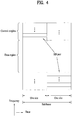
- Fig. 4 illustrates an uplink subframe structure.
- An uplink subframe may be divided into a control region and a data region in the frequency domain.
- a Physical Uplink Control Channel (PUCCH) carrying uplink control information is allocated to the control region and a Physical Uplink Shared Channel (PUSCH) carrying user data is allocated to the data region.
- PUCCH Physical Uplink Control Channel
- PUSCH Physical Uplink Shared Channel
- a UE does not transmit a PUSCH and a PUCCH simultaneously.
- a PUCCH for a UE is allocated to an RB pair in a subframe. The RBs of the RB pair occupy different subcarriers in two slots. Thus it is said that the RB pair allocated to the PUCCH is frequency-hopped over a slot boundary.
- SC-FDMA is also called DFT-s-OFDMA, different from later-described clustered DFT-s-OFDMA.
- SC-FDMA is a transmission scheme that keeps a Peak-to-Average Power Ratio (PARP) or Cube Metric (CM) value low and efficiently transmits a signal, avoiding the non-linear distortion area of a power amplifier.
- PAPR is a parameter representing waveform characteristics, computed by dividing the peak amplitude of a waveform by a time-averaged Root Mean Square (RMS) value.
- CM is another parameter representing a value that PAPR represents.
- PAPR is associated with a dynamic range that a power amplifier should support in a transmitter. That is, to support a high-PAPR transmission scheme, the dynamic range (or linear area) of the power amplifier needs to be wide. As a power amplifier has a wider dynamic range, it is more expensive. Therefore, a transmission scheme that maintains a PAPR value low is favorable for uplink transmission.
- SC-FDMA is employed as an uplink transmission scheme in the current 3GPP LTE system.
- Fig. 5 is a block diagram of an SC-FDMA transmitter.
- a serial-to-parallel converter 501 converts one block of N symbols input to the transmitter to parallel signals.
- An N-point DFT module 502 spreads the parallel signals and a subcarrier mapping module 503 maps the spread parallel signals to a frequency area. Each subcarrier signal is a linear combination of N symbols.
- An M-point Inverse Fast Fourier Transform (IFFT) module 504 converts the mapped frequency signals to time signals.
- a parallel-to-serial converter 505 converts the time signals to a serial signal and adds a CP to the serial signal.
- the DFT processing of the N-point DFT module 502 compensates for the effects of the IFFT processing of the M-point IFFT module 504 to a certain degree.
- the signals input to the DFT module 502 have a low PAPR which is increased after the DFT processing.
- the IFFT signals output from the IFFT module 504 may have a low PAPR again.
- Fig. 6 illustrates methods for mapping signals output from the DFT module 502 to a frequency area.
- a signal output from the SC-FDMA transmitter may satisfy the single carrier property by performing one of two mapping schemes illustrated in Fig. 6.
- Fig. 6(a) illustrates a localized mapping scheme in which the signals output from the DFT module 502 are mapped only to a specific part of a subcarrier area.
- Fig. 6(b) illustrates a distributed mapping scheme in which the signals output from the DFT module 502 are distributed across a total subcarrier area.
- the legacy 3GPP LTE standard (e.g. release 8) uses localized mapping.
- Fig. 7 is a block diagram illustrating transmission of a Reference signal (RS) for use in demodulating a signal transmitted in SC-FDMA.
- RS Reference signal
- the legacy 3GPP LTE standard e.g. release 8
- a time signal of data is converted to a frequency signal by DFT, mapped to subcarriers, IFFT-processed, and then transmitted (refer to Fig. 5 )
- an RS is generated directly in the frequency domain without DFT processing (701), mapped to subcarriers (702), IFFT-processed (703), attached with a CP, and then transmitted.
- Fig. 8 illustrates the positions of symbols to which RSs are mapped in an SC-FDMA subframe structure.
- Fig. 8(a) illustrates a case where an RS is positioned in the 4 th SC-FDMA symbol of each of two slots in a subframe, when a normal CP is used.
- Fig. 8(b) illustrates a case where an RS is positioned in the 3 rd SC-FDMA symbol of each of two slots in a subframe, when an extended CP is used.
- Clustered DFT-s-OFDMA is a modification to the above-described SC-FDMA, in which a DFT signal is divided into a plurality of sub-blocks and mapped to positions apart from each other in the frequency domain.
- Fig. 9 illustrates a clustered DFT-s-OFDMA scheme in a single carrier system.
- a DFT output may be divided in Nsb sub-blocks (sub-block #0 to sub-block #Nsb-1).
- the sub-blocks, sub-block #0 to sub-block #Nsb-1 are mapped to positions spaced from each other in the frequency domain on a single carrier (e.g. a carrier having a bandwidth of 20MHz).
- Each sub-block may be mapped to a frequency area in the localized mapping scheme.
- Figs. 10 and 11 illustrate clustered DFT-s-OFDMA schemes in a multi-carrier system.
- Fig. 10 illustrates an example of generating a signal through one IFFT module, when multiple carriers are contiguously configured (i.e. the respective frequency bands of the multiple carriers are contiguous) and a specific subcarrier spacing is aligned between adjacent carriers.
- a DFT output may be divided into Nsb sub-blocks (sub-block #0 to sub-block #Nsb-1) and the sub-blocks, sub-block #0 to sub-block #Nsb-1 may be mapped, in a one-to-one correspondence, to the Component Carriers (CCs), CC #0 to CC #Nsb-1 (each CC may have, for example, a bandwidth of 20MHz).
- Each sub-block may be mapped to a frequency area in the localized mapping scheme.
- the sub-blocks mapped to the respective CCs may be converted to a time signal through a single IFFT module.
- Fig. 11 illustrates an example of generating signals through a plurality of IFFT modules, when multiple carriers are non-contiguously configured (i.e. the respective frequency bands of the multiple carriers are non-contiguous).
- a DFT output may be divided into Nsb sub-blocks, sub-block #0 to sub-block #Nsb-1 and the sub-blocks, sub-block #0 to sub-block #Nsb-1 may be mapped, in a one-to-one correspondence, to the CCs, CC #0 to CC #Nsb-1 (each CC may have, for example, a bandwidth of 20MHz).
- Each sub-block may be mapped to a frequency area in the localized mapping scheme.
- the sub-blocks mapped to the respective CCs may be converted to time signals through respective IFFT modules.
- the clustered DFT-s-OFDMA scheme for a single carrier illustrated in Fig. 9 is intra-carrier DFT-s-OFDMA
- the clustered DFT-s-OFDMA schemes for multiple carriers illustrated in Figs. 10 and 11 are inter-carrier DFT-s-OFDMA.
- Intra-carrier DFT-s-OFDMA and inter-carrier DFT-s-OFDMA may be used in combination.
- Fig. 12 illustrates a chunk-specific DFT-s-OFDMA scheme in which DFT, frequency mapping, and IFFT are performed on a chunk basis.
- Chunk-specific DFT-s-OFDMA may also be referred to as Nx SC-FDMA.
- a code block resulting from code block segmentation is divided into chunks and the chunks are channel-encoded and modulated individually.
- the modulated signals are subjected to DFT, frequency mapping, and IFFT and the IFFT signals are summed and then added with a CP in the same manner as described with reference to Fig. 5 .
- the Nx SC-FDMA scheme illustrated in Fig. 12 is applicable to both a case of contiguous multiple carriers and a case of non-contiguous multiple carriers.
- MIMO does not depend on a single antenna path to receive a whole message. Rather, it completes the message by combining data fragments received through a plurality of antennas. Because MIMO can increase data rate within a certain area or extend system coverage at a given data rate, it is considered as a promising future-generation mobile communication technology that may find its use in a wide range including mobile terminals, relays, etc. MIMO can overcome a limited transmission capacity caused by increased data communication.
- MIMO schemes can be categorized into spatial multiplexing and spatial diversity depending on whether the same data is transmitted or not.
- spatial multiplexing different data is transmitted simultaneously through a plurality of Tx antennas.
- a transmission rate can be increased by as much as the number of transmission antennas.
- Spatial diversity is a scheme that achieves transmit diversity by transmitting the same data through a plurality of Tx antennas.
- Space time channel coding is an example of spatial diversity. Since the same data is transmitted through a plurality of Tx antennas, spatial diversity can maximize a transmission diversity gain (a performance gain). However, spatial diversity does not increase transmission rate.
- MIMO schemes may be categorized into open-loop MIMO (or channel-independent MIMO) and closed-loop MIMO (or channel-dependent MIMO) depending on whether a receiver feeds back channel information to a transmitter.
- Fig. 13 illustrates the configuration of a typical MIMO communication system.
- Fig. 13(a) when both the number of Tx antennas and the number of Rx antennas respectively to N T and N R , a theoretical channel transmission capacity is increased, compared to use of a plurality of antennas at only one of a transmitter and a receiver.
- the channel transmission capacity is increased in proportion to the number of antennas. Therefore, transmission rate and frequency efficiency can be increased remarkably.
- the transmission rate may be increased, in theory, to the product of R o and a transmission rate increase rate R i illustrated in Equation 1 due to an increase in channel transmission capacity in case of multiple antennas.
- R i min N T , N R
- a MIMO communication system with 4 Tx antennas and 4 Rx antennas may achieve a four-fold increase in transmission rate theoretically, relative to a single-antenna system.
- a different transmission power may be applied to each piece of transmission information, s 1 , s 2 , ⁇ , s N T .
- N T transmission signals x 1 , x 2 ⁇ , x N T may be generated by multiplying the transmission power-controlled information vector ⁇ by a weight matrix W .
- the weight matrix W functions to appropriately distribute the transmission information to the Tx antennas according to transmission channel states, etc.
- These N T transmission signals x 1 , x 2 , ⁇ , x N T are represented as a vector X , which may be determined by Equation 5.
- W ij denotes a weight between an i th Tx antenna and a j th piece of information. W is called a weight matrix or a precoding matrix.
- signals received at the respective Rx antennas, y 1 , y 2 , ⁇ , y N R may be represented as the following vector.
- y y 1 , y 2 , ⁇ , y N R T
- channels When channels are modeled in the MIMO communication system, they may be distinguished according to the indexes of Tx and Rx antennas and the channel between a j th Tx antenna and an i th Rx antenna may be represented as h ij . It is to be noted herein that the index of the Rx antenna precedes that of the Tx antenna in h ij .
- the channels may be represented as vectors and matrices by grouping them.
- the vector representation of channels may be carried out in the following manner.
- Fig. 13(b) illustrates channels from N T Tx antennas to an i th Rx antenna.
- all channels from the N T Tx antennas to the N R Rx antennas may be expressed as the following matrix.
- H h 1 T h 2 T ⁇ h i T ⁇ h N
- R T h 11 h 12 ⁇ h 1 N T h 12 h 12 ⁇ h 2 N T ⁇ ⁇ h i 2 h i 2 ⁇ h i N T ⁇ ⁇ h N R 1 h N R 2 ⁇ h N R N T
- AWGN Additive White Gaussian Noise
- the numbers of rows and columns in the channel matrix H representing channel states are determined according to the numbers of Tx and Rx antennas.
- the number of rows is identical to that of Rx antennas, N R and the number of columns is identical to that of Tx antennas, N T .
- the channel matrix H is of size N R xN T .
- the rank of a matrix is defined as the smaller between the numbers of independent rows and columns. Accordingly, the rank of the matrix is not larger than the number of rows or columns.
- the rank of the matrix H , rank( H ) is limited as follows. rank H ⁇ min N T , N R
- a transmitter and a receiver share a codebook including a predetermined number of precoding matrices according to a transmission rank, the number of antennas, etc. That is, if feedback information is finite, the precoding-based codebook scheme may be used.
- the receiver may measure channel states from received signals and feedback information about a finite number of preferred precoding matrices (i.e. the indexes of the precoding matrices) based on the afore-described codebook information. For example, the receiver may measure a received signal by Maximum Likelihood (ML) or Minimum Means Square Error (MMSE) and may select an optimum precoding matrix.
- ML Maximum Likelihood
- MMSE Minimum Means Square Error
- the receiver may transmit precoding matrix information for each codeword to the transmitter, which should not be construed as limiting the present invention.
- the transmitter may select a specific precoding matrix from a codebook based on the received information. After selecting the precoding matrix, the transmitter may precode a transmission signal by multiplying as many layer signals as a transmission rank by the selected precoding matrix and may transmit the precoded transmission signal through a plurality of antennas.
- the number of rows is equal to the number of antennas and the number of columns is equal to the rank in the precoding matrix. For example, if the number of Tx antennas is 4 and the number of layers is 2, the precoding matrix may be a 4x2 matrix.
- Equation 12 describes mapping of information mapped to layers to antennas by a precoding matrix.
- y 1 y 2 y 3 y 4 p 11 p 21 p 12 p 22 p 13 p 23 p 14 p 24 ⁇ x 1 x 2
- x 1 and x 2 denote information mapped to layers and each element of the 4x2 matrix
- p ij denotes a weight used for precoding
- y 1 , y 2 , y 3 and y 4 denote information mapped to the antennas, which may be transmitted through the respective antennas in OFDM.
- the receiver may recover the received signal by reversely performing the precoding of the transmitter.
- the reverse operation of precoding may be performed by multiplying a received signal by the Hermitian matrix P H of a precoding matrix used in precoding of the transmitter.
- the 3GPP LTE-A LTE Release-10) system may adopt uplink multi-antenna transmission in order to increase uplink transmission throughput.
- a multi-transmission stream or multi-transmission layer transmission scheme may be used for a single UE for the purpose of spatial multiplexing. This is called SU-MIMO.
- link adaptation may be applied to each individual transmission stream or transmission stream group.
- Different Modulation and Coding Schemes (MCSs) may be used for link adaptation.
- MCSs Modulation and Coding Schemes
- MCSs Modulation and Coding Schemes
- MCW Multiple CodeWord
- an MCW MIMO scheme for example, up to two CodeWords (CWs) may be transmitted simultaneously.
- information about an MCS used in a transmitter, a New Data Indicator (NDI) indicating whether transmitted data is new data or retransmission data, and a Redundancy Version (RV) indicating a transmitted sub-packet in case of retransmission is needed.
- An MCS, NDI, and RV may be defined for each Transport Block (TB).
- a plurality of TBs may be mapped to a plurality of CWs according to a transport block-to-codeword mapping rule. For example, let two RBs be denoted by TB1 and TB2 and let two CWs be denoted by CW0 and CW1. When the two TBs TB1 and TB2 are enabled, the first and second TBs TB1 and TB2 may be mapped respectively to the first and second CWs CW0 and CW1. Or the first TB TB1 may be mapped to the second CW CW1 and the second TB TB2 may be mapped to the first CW CW0 according to the value of a transport block-to-codeword swap flag.
- the enabled TB may be mapped to the first CW CW0. That is, a one-to-one mapping relationship is placed between TBs and CWs.
- TB disabling covers the size of a TB being 0. When the size of a TB is 0, the TB is not mapped to a CW.
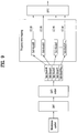
- FIG. 14 is a block diagram of an uplink MCW SU-MIMO transmission structure.
- one or more CWs may be scrambled with a UE-specific scrambling signal.
- the scrambled CWs are modulated to complex symbols in Binary Phase Shift Keying (BPSK), Quadrature Phase Shift Keying (QPSK), 16-ary Quadrature Amplitude Modulation (16QAM), or 64-ary QAM (64QAM) according to the type of a transmission signal and/or a channel state.
- BPSK Binary Phase Shift Keying
- QPSK Quadrature Phase Shift Keying
- 16QAM 16-ary Quadrature Amplitude Modulation
- 64QAM 64-ary QAM
- a codeword-to-layer mapping relationship may be established according to a transmission scheme as illustrated in [Table 1] and [Table 2].
- [Table 1] illustrates an example of transmitting a signal in spatial multiplexing
- [Table 2] illustrates an example of transmitting a signal in transmit diversity.
- x (a) (i) denotes an i th symbol of a layer with index a
- d (a) (i) denotes an i th symbol of a CW with index a.
- a mapping relationship between the number of CWs and the number of layers used for transmission may be known from "Number of layers” and "Number of codewords" in [Table 1] and [Table 2].
- "Codeword-to-Layer mapping" indicates how the symbols of each CW are mapped to a layer.
- one CW may be mapped to one layer on a symbol basis prior to transmission, one CW may be distributed to up to 4 layers as in the second case of [Table 2].
- the symbols of each CW are mapped sequentially to layers.
- a single encoder and a single modulation block exist.
- the layer-mapped signals may be subject to DFT.
- the layer-mapped signals may be multiplied by a specific precoding matrix selected according to a channel state and then assigned to Tx antennas.
- precoding may be performed in the frequency domain after DFT in the DFT-s-OFDMA structure.
- the antenna-specific transmission signals may be mapped to time-frequency REs for transmission and transmitted through the antennas after being processed in OFDM signal generators.
- FIG. 15 is exemplary block diagrams of layer shifting in an uplink MCW SU MIMO transmission structure.
- Layer shifting refers to permuting the order of mapping transmission streams or transmission layers on a time resource area unit (e.g. on an OFDM symbol basis or on a slot basis). Layer shifting may be performed before DFT ( Fig. 15(a) ) or after DFT ( Fig. 15(b) ). Or layer shifting may take place after OFDM signal generation. However, layer shifting is not always needed and thus may be excluded from uplink transmission.
- Precoding will be described in greater detail in relation to Figs. 14 and 15 .
- Precoding is a process of combining a transmission signal with a weight vector or a weight matrix to transmit a signal on spatial channels.
- the precoding blocks of Figs. 14 and 15 may implement transmit diversity, long-term beamforming, precoded signal multiplexing, etc.
- precoding weights may be constructed into a codebook. [Table 3] to [Table 7] illustrate exemplary codebooks used to prevent an increase in CM for uplink transmission.
- [Table 3] illustrates an exemplary codebook available for uplink spatial multiplexing transmission through 2 Tx antennas. Given two Tx antennas, one of 6 precoding matrices is available for rank-1 transmission and one precoding matrix is available for rank-2 transmission. [Table 3] Codebook Index Number of layers ⁇ 1 2 0 1 2 1 1 1 2 1 0 0 1 1 1 2 1 ⁇ 1 2 1 2 1 j 3 1 2 1 ⁇ j - 4 1 2 1 0 5 1 2 0 1
- Table 4 illustrates precoding matrices included in a 6-bit precoding codebook available for transmission of one layer (i.e. rank-1 transmission) in uplink spatial multiplexing transmission through 4 Tx antennas.
- rank-1 transmission For 4-Tx rank-1 transmission, one of a total of 24 precoding matrices may be used.
- Table 5 illustrates precoding matrices included in a precoding codebook available for transmission of 2 layers (i.e. rank-2 transmission) in an uplink spatial multiplexing transmission scheme using 4 Tx antennas.
- rank-2 transmission For 4-Tx rank-2 transmission, one of a total of 16 precoding matrices may be used.
- Table 6 illustrates precoding matrices included in a precoding codebook available for transmission of 3 layers (i.e. rank-3 transmission) in the uplink spatial multiplexing transmission scheme using 4 Tx antennas.
- rank-3 transmission For 4-Tx rank-3 transmission, one of a total of 12 precoding matrices may be used.
- [Table 7] illustrates precoding matrices included in a precoding codebook available for transmission of 4 layers (i.e. rank-4 transmission) in the uplink spatial multiplexing transmission scheme using 4 Tx antennas. For 4-Tx rank-4 transmission, only one precoding matrix may be used.
- Codebook Index 0 1 2 1 0 0 0 0 0 1 0 0 0 0 1 0 0 0 0 1 0 0 0 0 1
- a UE may transmit an RS and an eNB may acquire spatial channel information about an uplink directed from the UE to the eNB from the RS.
- the eNB may select a rank suitable for uplink transmission, acquire a precoding weight, and calculate Channel Quality Information (CQI) based on the acquired spatial channel information.
- the eNB may signal control information for uplink signal transmission to the UE.
- the control information may include uplink transmission resource assignment information, MIMO information (a rank, a precoding weight, etc.), an MCS level, HARQ information (an RV, an NDI, etc.), and uplink DM-RS sequence information.
- the UE may transmit an uplink signal using the control information received from the eNB.
- the present invention proposes a specific method for efficiently configuring MCS information, HARQ information, and MIMO information among control information that an eNB signals to a UE for uplink multi-antenna transmission.
- codeword-to-layer mapping relationships may be defined as illustrated in [Table] 1.
- a transmission rank may be 1 or 2.
- rank-2 transmission of one CW may be limited to retransmission.
- the transmission rank may be 2, 3 or 4.
- control information may include two MCS levels, two RVs, and two NDIs.
- This control information for MCW uplink transmission may be transmitted to a UE in a DCI format on a PDCCH.
- an MCS field may be 5 bits.
- [Table 8] and [Table 9] illustrate exemplary configurations of an MCS field for downlink data transmission (a PDSCH) and uplink data transmission (a PUSCH).
- an MCS field may be configured for a PDSCH to represent 29 states that indicate MCSs by combining modulation orders and Transport Block Sizes (TBSs) and 3 states indicating MCSs by modulation orders only.
- TBSs Transport Block Sizes
- an MCS field may be configured for a PUSCH to represent 29 states indicated by combining modulation orders, TBS indexes, and RV value '0' and 3 states indicated by RVs only.
- Control information for downlink transmission may include MCS bits, an RV bit, and an NDI bit.
- a modulation order, a coding rate, and an RV may be determined for new transmission and retransmission by combining these information.
- disabling of the CW may be indicated by the following signaling.
- [Table 9] illustrates an MCS table for uplink single CW transmission.
- Control information for uplink transmission includes MCS bits and an NDI bit, and RV information is included in the MCS table (i.e. the RV information and MCS information are jointly encoded).
- the control information for uplink data transmission does not include an RV field.
- Method 1 whether a CW is disabled in uplink MCW transmission is indicated by redefining one or more states defined in a conventional MCS table for other usages.
- Embodiment 1-1 it is assumed that MCS fields are defined to support two CWs and a part of an MCS field for a second TB may be redefined for other usage.
- an MCS state indicating the lowest modulation order and the smallest TBS may be redefined to represent a TB disabled state.
- MCS index #0 indicating the lowest modulation order and the smallest TBS may be redefined to represent a TB disabled state.
- an MCS state indicating the highest modulation order and the largest TBS may be redefined to represent a TB disabled state.
- MCS index #28 indicating the highest modulation order and the largest TBS may be redefined to represent a TB disabled state.
- a part of states indicating only RVs may be redefined to represent a TB disabled state among states represented by a second MCS field for a second TB.
- MCS index #31 indicates that an MCS and a TBS are reserved and an RV is '3' in [Table 9].
- MCS index #31 in the MCS field for the second TB may be used to indicate the TB disabled state.
- MCS index #31 is purely exemplary and thus MCS indexes #29 and #30 may be used for the same usage.
- a part of MCS states indicating only RVs may be redefined to represent TB disabled among MCS states represented by an MCS table.
- the TB disabled state is redefined for each of a plurality of MCS tables.
- MCS index #31 indicates that an RV is '3' and an MCS and a TBS are reserved in [Table 9].
- MCS index #31 for the MCS field for the second TB may be used to indicate TB disabled.
- MCS index #31 is purely exemplary and thus MCS indexes #29 and #30 may be used for the same usage.
- Embodiment 1-6 a part of states indicating modulation orders and TBSs that have the same spectral efficiency may be used to indicate TB disabled among fields defined in an MCS table.
- a new MCS table is defined with a part of a conventional 5-bit MCS table. Accordingly, the new MCS table may have a smaller size than the conventional MCS table, for example, 2 or 3 bits.
- the new MCS table may include information about CW disabling. That is, a specific state may be defined as the TB disabled state in the new 2-bit or 3-bit MCS table.
- Method 3 interprets a conventional MCS field and NDI field in a different manner. That is, an MCS field including a modulation order, a TBS, and RV information and an NDI field are considered together. Thus, a specific combination may be interpreted to represent the TB disabled state.
- MCS indexes #29 to #31 are used to indicate new RVs.
- MCS indexes #29 to #31 indicating new RVs are used only for retransmission and a modulation order for retransmission is the same as for initial transmission.
- An NDI bit is not toggled at retransmission (e.g. If the NDI is 0 at initial transmission, the NDI is still 0 at retransmission. If the NDI is 1 at initial transmission, the NDI is still 1 at retransmission). That is, if MCSs #29 to #31 are indicated for retransmission, the NDI bit is basically not toggled.
- the present invention proposes a method for indicting a TB disabled state by combining an MCS field with an NDI bit.
- a combination of an MCS index indicating an RV only and an NDI bit value may be considered as a method for indicating a disabled TB.
- an MCS field indicates only an RV (i.e. indicates one of MCS indexes #29 to #31) and an NDI bit has been toggled from a previous transmission, this may be newly interpreted as indicating TB disabled.
- an HARQ buffer may be flushed.
- the NDI bit is toggled at the next transmission, and the MCS field indicates a modulation order, a TBS, and RV '0' like MCS indexes #0 to #28, a new transmission is attempted.
- ACK/NACK information for one TB may be represented using one PHICH resource. For instance, in case of layer shifting, it can be said that the error probabilities of two CWs (or TBs) are equal. Therefore, one PHICH resource is sufficient to represent ACK/NACK information.
- an ACK/NACK may be represented for a transmitted TB using a PHICH having a state indicating the number of transmitted TBs.
- a single NDI field may indicate that the two TBs are new data or retransmission data, instead of two NDI fields. Accordingly, one NDI field may be defined for each TB or all TBs.
- bit fields may be configured as control information for supporting MCW MIMO transmission by considering the above description comprehensively.
- control information may be configured so as to have two MCS fields (of the same bit size) and two NDI fields.
- MCS 5 bits
- NDI 1bit
- control information is configured as in Case 1, implementation of Embodiment 1-2 or 1-3 in Method 1 will be described.
- an MCS field for one TB indicates RV '0', the lowest modulation order, and the smallest TBS (i.e. MCS index #0) or if the MCS field indicates RV '0', the highest modulation order, and the largest TBS (i.e. MCS index #28), this may mean that the TB is disabled.
- control information may be configured so as to have two MCS fields (of the same bit size) and one NDI field.
- MCS 5 bits
- NDI 1 bit.
- control information may be configured in such a manner that one of two MCS fields has a bit size equal to a part of the bit size of the other MCS field (see Method 2) and two NDI fields are defined.
- MCS 5 bits
- NDI 1 bit.
- MCS N (N ⁇ 5) bits
- NDI 1 bit.
- control information may be configured in such a manner that one of two MCS fields has a bit size equal to a part of the bit size of the other MCS field (see Method 2) and one NDI field is defined.
- MCS 5 bits
- NDI 1 bit.
- MCS N (N ⁇ 5) bits
- various MCS and NDI combinations may be produced for uplink MCW MIMO transmission.
- an enabled or disabled CW can be indicated by interpreting an MCS field in the above-described manners.
- control information that schedules uplink MIMO transmission (a DCI format).
- the present invention proposes a method for configuring control information that efficiently indicates precoding information for MIMO transmission, using the number of enabled TBs indicated through interpretation of the control information as information.
- one of the TBs when two TBs are enabled, one of the TBs may be mapped to a first CW CW0 and the other TB may be mapped to a second CW CW1 (swapping of transport block-to-codeword mapping is included). If only one of the two TBs is enabled, the enabled TB is mapped to the first CW, CW0.
- precoding Information size Rank-1 24 Rank-2 16 Rank-3 12 Rank-4 1
- Uplink transmission ranks that are available according to numbers of enabled CWs may be summarized, taking into account a codeword-to-layer mapping relationship in [Table 12] and [Table 13].
- [Table 12] lists ranks according to numbers of enabled CWs, for 2 Tx antennas and
- [Table 13] lists ranks according to numbers of enabled CWs, for 4 Tx antennas.
- [Table 12] One CW Two CW Rank-1 Rank-2
- [Table 13] One CW Two CW Rank-1 Rank-2 Rank-2 Rank-3 Rank4
- the size of necessary precoding information may be defined according to the number of enabled CWs.
- [Table 14] and [Table 15] may be built by substituting the sizes of precoding information based on ranks listed in [Table 10] and [Table 11] into [Table 12] and [Table 13].
- [Table 14] is for 2 Tx antennas and [Table 14] is for 4 Tx antennas.
- whether only one CW or both CWs are enabled in [Table 14] and [Table 15] may be indicated by interpreting an MCS field and/or other information in uplink MIMO control information (a DCI format) as proposed in Method 1, Method 2 and Method 3.
- all precoding information for 2 Tx antennas may be represented in 3 bits (a total of 8 states can be represented).
- all precoding information for 4 Tx antennas may be represented in 6 bits (a total of 64 states can be represented).
- a precoding information field may be interpreted differently according to the number of enabled CWs.
- the number of enabled CWs may be known depending on whether a TB is enabled or not in Method 1, Method 2, and Method 3. For example, when two TBs are enabled, it may be determined that two CWs are enabled. On the other hand, if one of the two TBs is disabled, it may be determined that only the first CW, CW0 is enabled. Since the number of enabled CWs can be determined in this manner, the precoding information field may indicate rank information and a precoding matrix index differently according to the number of enabled CWs.
- each of 6 states of precoding information indicates rank-1 transmission and a precoding matrix to be used for uplink transmission. For example, if the bit value of precoding information is 0, this indicates a precoding matrix with codebook index 0 and if the bit value of precoding information is 1, this indicates a precoding matrix with codebook index 1 in the case of 1 layer in [Table 3]. Meanwhile, in the case where the bit value of the precoding information is 0, if two CWs are enabled, this indicates rank-2 transmission and a precoding matrix with codebook index 0 in the case of 2 layers in [Table 3]. In other words, even though the precoding information has the same bit value, the precoding information may represent different rank information and precoding matrix information according to the number of enabled CWs.
- precoding information having the same bit value may represent different rank information and precoding matrix information according to the number of enabled CWs. For example, it is assumed that precoding information has a bit value of 4 in [Table 15]. If one CW is enabled, the precoding information may represent rank-1 transmission and a precoding matrix with codebook index 4 in [Table 5].
- the present invention can efficiently provide uplink scheduling control information by reducing signaling overhead.
- precoding information field if the size of a precoding information field is defined as described before, remaining states that are represented by precoding information may be reserved for other control information.
- a reserved bit of the precoding information field may be used to represent a state where single antenna transmission or 1-CW transmission is allowed, when MIMO transmission is set.
- precoding information may be configured as illustrated in [Table 16] and [Table 17].
- Bits indicating precoding information may be efficiently used by reducing the number of states represented by the precoding information. For example, the bits of precoding information may be decreased from 6 bits to 5 bits.
- a precoding weight for rank-2 transmission of one CW may be expressed as a subset of a precoding weight for rank-2 transmission of two CWs.
- a precoding weight for rank-2 transmission of one CW may be expressed as a subset of a precoding weight for rank-2 transmission of two CWs.
- a rank-2 precoding weight includes 16 elements, a part of the elements may be used as a precoding weight for rank-2 transmission of one CW.
- precoding information may be configured only with a rank-1 codebook and a rank-2 codebook.
- the rank-2 codebook represents N (N ⁇ 12) states.
- [Table 18] to [Table 21] illustrate cases where a rank-2 codebook for transmission of one CW has 12, 8, 6 and 4 states, respectively, for 4 Tx antennas.
- precoding information is configured so as to represent states for a rank-1 codebook, a rank-2 codebook, and the simplest transmission scheme (e.g. single-antenna transmission).
- the rank-2 codebook represents N (N ⁇ 11) states. [Table 22] to [Table 25] illustrate cases where the rank-2 codebook represents 11, 8, 6 and 4 states, respectively in case of one CW transmission, for 4 Tx antennas.
- the precoding information field may be configured as illustrated in [Table 32], [Table 33], and [Table 34], taking the above description into comprehensive account.
- [Table 32] illustrates contents of a 3-bit precoding information field for 2 Tx antennas
- [Table 33] illustrates contents of a 5-bit precoding information field for 4 Tx antennas
- [Table 34] illustrates contents of a 6-bit precoding information field for 4 Tx antennas.
- Control information (a DCI format) for uplink MCW MIMO transmission in the 3GPP LTE-A system may be configured as follows, based on the above description.
- the legacy 3GPP LTE standard (e.g. 3GPP LTE Release-8) defines a single-antenna port transmission mode for uplink transmission and defines DCI format 0 to support the single-antenna port transmission mode.
- DCI format 0 may include 'Flag for format 0/format 1A differentiation', 'Hopping flag', 'Resource block allocation (for contiguous allocation) and hopping resource allocation', 'MCS and redundancy version', 'NDI', 'TPC command for scheduled PUSCH', 'Cyclic shift for DMRS', and 'CQI request'.
- Contiguous resource allocation and single-antenna transmission may be supported using DCI format 0. Meanwhile, non-contiguous resource allocation and uplink spatial multiplexing transmission using up to 4 transmission layers may be introduced to LTE-A uplink transmission. To support this new uplink transmission scheme, it is necessary to define a new transmission mode and a new DCI format for control signaling of the new transmission mode.
- a closed-loop spatial multiplexing transmission mode using multiple TBs and a closed-loop spatial multiplexing transmission mode using a single TB may be newly defined as uplink transmission modes.
- the uplink single-antenna transmission mode as defined by 3GPP LTE Release-8 needs to be supported as a default transmission mode.
- transmission of up to two TBs from a scheduled UE may be considered.
- Each individual TB may have an MCS level.
- two MCS indicators for the two TBs may be included in uplink scheduling control information (a DCI format).
- precoding information for all transmission ranks may be included in the control information.
- uplink scheduling control information (a DCI format) may include one MCS level and rank-1 precoding information.
- the single-antenna uplink transmission mode which is a default transmission mode, may be defined as an uplink transmission mode available before an eNB knows the Tx antenna configuration of a UE. This transmission mode may be used as a fall-back transmission mode of the 3GPP LTE Release-10 uplink transmission mode.
- new uplink scheduling control information (a new DCI format) needs to be defined. Requirements of control signaling to support uplink SU-MIMO transmission will be described below with reference to [Table 35].
- [Table 35] illustrates an example of a new DCI format for PUSCH transmission in the LTE-A system.
- mode A is the multi-TB closed-loop spatial multiplexing mode
- mode B is the single-TB closed-loop spatial multiplexing mode.
- the 'Flag for UL/DL format differentiation' field provides control information indicating whether the DCI format is for UL transmission or DL transmission. Since the DCI format for uplink SU-MIMO transmission has the same size as the DCI format for downlink SU-MIMO transmission, the number of PDCCH blind decodings can be reduced.
- the number of bits of the 'Flag for UL/DL format differentiation' field is 0 or 1. If this field is included in the DCI format, the field has 1 bit. When needed, this field is not included in the DCI format.
- the 'Hopping flag and resource block assignment' field may not be needed because a frequency hopping mode may operate according to non-contiguous resource allocation. If a resource block assignment field for non-contiguous assignment has the same size as a resource block assignment field for LTE Realease-8 uplink transmission, a new DCI format having the same size as the existing DCI format 0 may be designed. Non-contiguous resource assignment may be used for uplink SU-MIMO transmission. The number of bits of the 'Hopping flag and resource block assignment' field is 0 or 1. If this field is included in the DCI format, the field has 1 bit. When needed, this field is not included in the DCI format.
- a channel carrying each CW is independent.
- independent 'MCS and RV' and 'NDI' fields may be defined for each CW for uplink SU-MIMO transmission, like control information for downlink MIMO transmission in the LTE Release-8 system.
- the 'MCS and RV' and 'NDI' fields for the first CW may be 5 bits and 1 bit long, respectively, as in the conventional DCI format 0.
- the 'MCS and RV' and 'NDI' fields for the second CW may be 5 bits and 1 bit long, respectively.
- the 'MCS and RV' field for the second CW may have fewer than 5 bits, as described before.
- new data may be transmitted for a CW for which an ACK has been received and retransmission data may be transmitted for a CW for which a NACK has been received.
- new data may be transmitted if ACKs have been received for two CWs. If an ACK has been received for one of the CWs and a NACK has been received for the other CW, retransmission may be attempted for the CW for which the NACK has been received, while no transmission may be performed for the CW for which the ACK has been received. If NACKs have been received for the two CWs, retransmission may be performed for the two CWs.
- an NDI field for the second CW is needed in the DCI format.
- a TB is enabled or disabled in order to support transmission of one of two TBs.
- some state of an MCS table may be interpreted differently or a state indicating TB disabled may be added to the MCS table. For example, it may indicate that a corresponding TB is disabled by signaling MCS index #0 or #28.
- a 3-bit precoding codebook may be used for a UE with 2 Tx antennas for uplink spatial multiplexing
- a 6-bit precoding codebook may be used for a UE with 4 Tx antennas for uplink spatial multiplexing.
- the precoding information field may be configured according to various embodiments of the present invention. For example, precoding information may be efficiently configured as illustrated in [Table 12] to [Table 15], as described before.
- the 'TB to Codeword swap flag' field provides control information indicating whether swapping occurs to TB to codeword mapping.
- the 'Cyclic shift for DMRS' field indicates a cyclic shift value applied to an uplink DMRS.
- Uplink DMRSs may be multiplexed by separating the uplink DMRSs using cyclic shifts during multi-layer channel estimation.
- cyclic shift indexes are assigned to multiple layers, the minimum number of bits required to indicate a cyclic shift is 3 bits. If a cyclic shift is indicated for one layer, cyclic shift indexes may be allocated to other layers according to a predefined rule.
- the 'OCC' field indicates an orthogonal cover code applied to uplink DMRSs.
- the use of an OCC may increase orthogonal resources for uplink DMRSs.
- 'TPC command for scheduled PUSCH' includes a transmission power command for transmission of a scheduled PUSCH. If a UE has multiple antennas, TPC commands may be applied to the respective antennas.
- the 'UL index (for TDD)' field may indicate a subframe index set for uplink transmission in a specific uplink-downlink configuration, when a radio frame is configured in TDD mode.
- the 'Downlink Assignment Index (for TDD)' field may specify the total number of subframes set for PDSCH transmission in a specific uplink-downlink configuration, when a radio frame is configured in the TDD mode.
- the 'CQI request' field indicates a request for reporting CQI, a PMI, and an RI non-periodically on a PUSCH. If the 'CQI request' field is set to 1, a UE transmits a non-periodical CQI, PMI, and RI report on a PUSCH.
- Control information that schedules uplink SU-MIMO transmission can be efficiently provided, while reducing signaling overhead, by means of the new DCI format.
- Fig. 16 illustrates a method for providing control information that schedules uplink multi-antenna transmission according to an embodiment of the present invention.
- the eNB may generate DCI including MCS information for each of first and second TBs, TB1 and Tb2 (S1610).
- the DCI is control information that schedules uplink transmission of at least one of the TBs, TB1 and TB2.
- the eNB may transmit the generated DCI to a UE on a PDCCH (S1620).
- the eNB may receive an uplink signal scheduled according to the DCI on a PUSCH from the UE (S1630).
- the UE may receive the DCI transmitted in step S1620 (S1640) and transmit at least one of the TBS, TB1 and TB2 on the PUSCH to the eNB according to the scheduling information included in the DCI (S1650).
- MCS information for TB1 or TB2 may indicate that the corresponding TB is disabled.
- Fig. 17 illustrates a method for providing control information that schedules uplink multi-antenna transmission according to another embodiment of the present invention.
- the eNB may generate DCI including precoding information that specifies a transmission rank and a precoding matrix for uplink transmission (S1710).
- the DCI is control information that schedules uplink transmission.
- the eNB may transmit the generated DCI to a UE on a PDCCH (S1720).
- the eNB may receive an uplink signal scheduled according to the DCI on a PUSCH from the UE (S1730).
- the UE may receive the DCI transmitted in S1720 (S1740) and transmit uplink data on the PUSCH to the eNB according to the transmission rank and the precoding matrix indicated by the scheduling information included in the DCI (S1750).
- the size of precoding information included in the DCI may be determined based on the number of multiple antennas and the number of precoding matrices available according to an uplink transmission rank.
- the precoding information may be configured so as to indicate a different transmission rank and precoding matrix according to the number of enabled CWs.
- rank-1 transmission is possible and when two CWs are enabled, rank-2 transmission is possible.
- rank-1 transmission or rank-2 transmission is possible and when two CWs are enabled, rank-2 transmission, rank-3 transmission, or rank-4 transmission is possible.
- the number of enabled CWs is equal to that of enabled TBs. Disabling of a TB may be indicated by a specific value (e.g. MCS index #0 or #28) set in an MCS field for each TB included in DCI as in Method 1, Method 2, and Method 3. Therefore, precoding information may be interpreted differently according to the number of enabled CWs. The size of precoding information may be determined based on a larger number of states according to the number of enabled CWs.
- precoding information should be able to represent 6 states indicating 6 precoding matrices for rank 1.
- the precoding information should be able to represent one state indicating one precoding matrix for rank 2. Therefore, the size of precoding information may be 3 bits (8 states). As described before, remaining states other than states indicating transmission ranks and precoding matrices may be reserved or used to represent other information.
- precoding information should be able to represent 24 states indicating 24 precoding matrices for rank 1 and 16 states indicating 16 precoding matrices for rank 2 (a total of 40 states).
- the precoding information should be able to represent 16 states indicating 16 precoding matrices for rank 2, 12 states indicating 12 precoding matrices for rank 3, and one state indicating one precoding matrix for rank 4 (a total of 29 states). Therefore, the size of precoding information may be 6 bits (64 states). As described before, remaining states other than states indicating transmission ranks and precoding matrices may be reserved or used to represent other information.
- a new DCI format may be configured by using the method for indicating a disabled TB ( Fig. 16 ) and the method for configuring precoding information ( Fig. 17 ) in combination, for uplink SU-MIMO transmission.
- DCI may be configured to schedule uplink multi-antenna transmission by applying one or more of the foregoing various embodiments of the present invention simultaneously.
- Fig. 18 is a block diagram of an eNB and a UE according to an embodiment of the present invention.
- An eNB 1810 may include an Rx module 1811, a Tx module 1812, a processor 1813, a memory 1814, and antennas 1815.
- the Rx module 1811 may receive data and control signals from the outside (e.g. a UE).
- the Tx module 1812 may transmit data and control signals to the outside (e.g. a UE).
- the processor 1813 may be connected to various components of the eNB 1810 such as the Rx module 1811, the Tx module 1812, and the memory 1814 in terms of communication and may provide overall control to the eNB 1810 and its components.
- the eNB 1810 may support MIMO transmission and reception by a plurality of antennas 1815.
- the eNB 1810 may provide control information that schedules uplink multi-antenna transmission to the UE.
- the processor 1813 of the eNB 1810 may be configured so as to generate DCI including MCS information for each of first and second TBs.
- the processor 1813 may generate DCI including precoding information that specifies a transmission rank and a precoding matrix for uplink transmission.
- the processor 1813 may also transmit the DCI that schedules uplink transmission on a downlink control channel through the Tx module 1812.
- the processor 1813 may receive an uplink signal scheduled based on the DCI on an uplink data channel through the Rx module 1811.
- MCS information for one of the first and second TBs may indicate the corresponding TB is disabled.
- the size of the precoding information may be determined according to the number of multiple antennas and the number of precoding matrices available according to an uplink transmission rank.
- the processor 1813 may process information received at the eNB 1810 and information to be transmitted to the outside.
- the memory 1814 may store processed information for a predetermined time and may be replaced by a component such as a buffer (not shown).
- eNB 1810 has been described as an uplink receiver in Fig. 18 , the same thing may apply to a Relay Node (RN) that is also an uplink receiver.
- RN Relay Node
- a UE 1820 may include an Rx module 1821, a Tx module 1822, a processor 1823, a memory 1824, and antennas 1825.
- the Rx module 1821 may receive data and control signals from the outside (e.g. an eNB).
- the Tx module 1822 may transmit data and control signals to the outside (e.g. an eNB).
- a processor 1823 may be connected to various components of the UE 1820 such as the Rx module 1821, the Tx module 1822, and the memory 1824 in terms of communication and may provide overall control to the UE 1820 and its component.
- the UE 1820 may support MIMO transmission and reception by a plurality of antennas 1825.
- the UE 1820 may perform uplink multi-antenna transmission.
- the processor 1823 of the UE 1820 may be configured so as to receive DCI that schedules uplink transmission on a downlink control channel through the Rx module 1821.
- the processor 1823 may transmit an uplink signal scheduled according to the received DCI on an uplink data channel through the Tx module 1822.
- the DCI includes MCS information for each of first and second TBs.
- MCS information for one of the first and second TBs has a predetermined value (e.g. MCS index #0 or #28), it may indicate that the corresponding TB is disabled.
- the DCI may include precoding information that specifies a transmission rank and a precoding matrix for uplink transmission. The size of the precoding information may be determined according to the number of multiple antennas and the number of precoding matrices available according to an uplink transmission rank.
- the processor 1823 may process information received at the UE 1820 and information to be transmitted to the outside.
- the memory 1824 may store processed information for a predetermined time and may be replaced by a component such as a buffer (not shown).
- UE 1820 has been described as an uplink transmitter in Fig. 18 , the same thing may apply to an RN that is also an uplink transmitter.
- the embodiments of the present invention may be achieved by various means, for example, hardware, firmware, software, or a combination thereof.
- the methods according to the embodiments of the present invention may be achieved by one or more Application Specific Integrated Circuits (ASICs), Digital Signal Processors (DSPs), Digital Signal Processing Devices (DSDPs), Programmable Logic Devices (PLDs), Field Programmable Gate Arrays (FPGAs), processors, controllers, microcontrollers, microprocessors, etc.
- ASICs Application Specific Integrated Circuits
- DSPs Digital Signal Processors
- DSDPs Digital Signal Processing Devices
- PLDs Programmable Logic Devices
- FPGAs Field Programmable Gate Arrays
- processors controllers, microcontrollers, microprocessors, etc.
- an embodiment of the present invention may be implemented in the form of a module, a procedure, a function, etc.
- Software code may be stored in a memory unit and executed by a processor.
- the memory unit is located at the interior or exterior of the processor and may transmit and receive data to and from the processor via various known means.
Landscapes
- Engineering & Computer Science (AREA)
- Signal Processing (AREA)
- Computer Networks & Wireless Communication (AREA)
- Quality & Reliability (AREA)
- Mobile Radio Communication Systems (AREA)
- Radio Transmission System (AREA)
Applications Claiming Priority (4)
| Application Number | Priority Date | Filing Date | Title |
|---|---|---|---|
| US30696910P | 2010-02-23 | 2010-02-23 | |
| US32076310P | 2010-04-04 | 2010-04-04 | |
| US32108610P | 2010-04-05 | 2010-04-05 | |
| PCT/KR2011/001270 WO2011105813A2 (ko) | 2010-02-23 | 2011-02-23 | 상향링크 다중 안테나 전송을 지원하는 무선 통신 시스템에서 상향링크 전송을 위한 제어정보를 제공하는 방법 및 장치 |
Publications (3)
| Publication Number | Publication Date |
|---|---|
| EP2541797A2 EP2541797A2 (en) | 2013-01-02 |
| EP2541797A4 EP2541797A4 (en) | 2017-04-05 |
| EP2541797B1 true EP2541797B1 (en) | 2018-12-19 |
Family
ID=44507429
Family Applications (2)
| Application Number | Title | Priority Date | Filing Date |
|---|---|---|---|
| EP11747700.0A Active EP2541796B1 (en) | 2010-02-23 | 2011-02-23 | Method and device for providing control information for uplink transmission in wireless communication system supporting uplink multi-antenna transmission |
| EP11747703.4A Active EP2541797B1 (en) | 2010-02-23 | 2011-02-23 | Method and device for providing control information for uplink transmission in wireless communication system supporting uplink multi-antenna transmission |
Family Applications Before (1)
| Application Number | Title | Priority Date | Filing Date |
|---|---|---|---|
| EP11747700.0A Active EP2541796B1 (en) | 2010-02-23 | 2011-02-23 | Method and device for providing control information for uplink transmission in wireless communication system supporting uplink multi-antenna transmission |
Country Status (5)
| Country | Link |
|---|---|
| US (3) | US9166661B2 (ko) |
| EP (2) | EP2541796B1 (ko) |
| JP (2) | JP5841075B2 (ko) |
| CN (1) | CN102859896B (ko) |
| WO (2) | WO2011105813A2 (ko) |
Families Citing this family (75)
| Publication number | Priority date | Publication date | Assignee | Title |
|---|---|---|---|---|
| US8553624B2 (en) * | 2007-10-10 | 2013-10-08 | Samsung Electronics Co., Ltd. | Asynchronous hybrid ARQ process indication in a MIMO wireless communication system |
| US9055576B2 (en) * | 2009-10-08 | 2015-06-09 | Qualcomm Incorporated | Uplink resource allocation for LTE advanced |
| US9379844B2 (en) * | 2010-02-24 | 2016-06-28 | Samsung Electronics Co., Ltd. | Method and system for indicating an enabled transport block |
| CN101834629B (zh) * | 2010-04-06 | 2014-10-22 | 中兴通讯股份有限公司 | 一种指示传输参数的方法及系统 |
| KR20110122046A (ko) * | 2010-05-03 | 2011-11-09 | 주식회사 팬택 | 무선통신 시스템에서 하향링크 제어정보의 전송장치 및 방법 |
| EP2567468B1 (en) * | 2010-05-04 | 2020-01-22 | Samsung Electronics Co., Ltd | Method of control indication in multi-input multi-output communication systems |
| JP5009410B2 (ja) * | 2010-10-29 | 2012-08-22 | シャープ株式会社 | 移動局装置、無線通信方法および集積回路 |
| EP2684328B1 (en) * | 2011-03-30 | 2016-06-22 | Huawei Technologies Co., Ltd. | Method and apparatus for open loop transmission in a multiple antenna wireless communication system |
| CN102882657B (zh) * | 2011-07-15 | 2018-01-23 | 瑞典爱立信有限公司 | 用于上行链路秩自适应的方法、设备和系统 |
| WO2013013392A1 (zh) * | 2011-07-27 | 2013-01-31 | 富士通株式会社 | 一种控制信令的传输方法和装置 |
| US9826514B2 (en) | 2011-11-16 | 2017-11-21 | Qualcomm Incorporated | Downlink control information (DCI) design for low cost devices |
| US8761108B2 (en) * | 2012-06-25 | 2014-06-24 | Telefonaktiebolaget L M Ericsson (Publ) | Table based link adaption for wireless communication transmissions with one codeword |
| US20160219582A1 (en) * | 2012-10-15 | 2016-07-28 | Nokia Solutions And Networks | Flexible frame structure |
| WO2014098358A1 (ko) * | 2012-12-18 | 2014-06-26 | 엘지전자 주식회사 | 데이터 수신 방법 및 장치 |
| CN104025470B (zh) * | 2012-12-31 | 2018-09-07 | 华为技术有限公司 | 报告信道状态信息csi的方法、用户设备和基站 |
| EP2787670A1 (en) * | 2013-04-05 | 2014-10-08 | Panasonic Intellectual Property Corporation of America | MCS table adaptation for 256-QAM |
| WO2014175800A1 (en) * | 2013-04-26 | 2014-10-30 | Telefonaktiebolaget Lm Ericsson (Publ) | Method and network efficiency node for increased data throughput in wireless networks |
| WO2014189417A1 (en) * | 2013-05-21 | 2014-11-27 | Telefonaktiebolaget L M Ericsson (Publ) | Method and network node for measuring an uplink channel which uses a precoding matrix selected by the network node |
| KR102065696B1 (ko) * | 2013-08-01 | 2020-01-14 | 삼성전자주식회사 | 무선 통신 시스템에서 적응적 송신 전력 정규화를 위한 장치 및 방법 |
| WO2015141961A1 (ko) * | 2014-03-21 | 2015-09-24 | 주식회사 케이티 | 전송 블록 크기 결정 방법 및 장치 |
| US9634744B2 (en) * | 2014-05-12 | 2017-04-25 | Taiwan Semiconductor Manufacturing Company, Ltd. | Sparsity enhanced mismatch model for heterogeneous networks with doubly-selective fading channels |
| EP4024799A1 (en) | 2014-07-29 | 2022-07-06 | Telefonaktiebolaget LM Ericsson (publ) | Signaling of modulation configuration |
| US10764012B2 (en) * | 2014-11-06 | 2020-09-01 | Qualcomm Incorporated | Reducing processing time for low latency transmission and reception |
| EP3048744A1 (en) * | 2015-01-26 | 2016-07-27 | Alcatel Lucent | Method for transmitting synchronization signals in telecommunication |
| WO2016123393A1 (en) * | 2015-01-28 | 2016-08-04 | Interdigital Patent Holdings, Inc. | Downlink control signaling |
| CN105099621B (zh) | 2015-06-29 | 2018-05-22 | 珠海市魅族科技有限公司 | 通信方法和通信设备 |
| US9794921B2 (en) * | 2015-07-14 | 2017-10-17 | Motorola Mobility Llc | Method and apparatus for reducing latency of LTE uplink transmissions |
| EP3328145B1 (en) * | 2015-08-12 | 2021-06-30 | Huawei Technologies Co., Ltd. | Data transmission method, terminal equipment, base station, and communication system |
| EP3131225B1 (en) * | 2015-08-14 | 2019-03-13 | Sun Patent Trust | Modulation order adaptation for partial subframes |
| CN112910622B (zh) * | 2015-11-06 | 2021-11-30 | 中兴通讯股份有限公司 | 信道状态测量导频的配置方法及装置、解析方法及装置 |
| KR20180129875A (ko) * | 2016-04-26 | 2018-12-05 | 삼성전자주식회사 | 업링크 mimo를 가능하게 하기 위한 방법 및 장치 |
| US10419086B2 (en) | 2016-04-26 | 2019-09-17 | Samsung Electronics Co., Ltd. | Method and apparatus for enabling uplink MIMO |
| US10367677B2 (en) | 2016-05-13 | 2019-07-30 | Telefonaktiebolaget Lm Ericsson (Publ) | Network architecture, methods, and devices for a wireless communications network |
| US10630410B2 (en) | 2016-05-13 | 2020-04-21 | Telefonaktiebolaget Lm Ericsson (Publ) | Network architecture, methods, and devices for a wireless communications network |
| CN109565871B (zh) * | 2016-05-26 | 2022-03-11 | 诺基亚技术有限公司 | 用于非正交编码接入的码字自适应 |
| US10326558B2 (en) | 2016-07-20 | 2019-06-18 | Intel Corporation | Apparatus, system and method of communicating a single carrier (SC) transmission |
| KR20180013171A (ko) * | 2016-07-28 | 2018-02-07 | 삼성전자주식회사 | 이동 통신 시스템에서 harq 프로세스 관리 방법 및 장치 |
| RU2713411C1 (ru) | 2016-09-12 | 2020-02-05 | Гуандун Оппо Мобайл Телекоммьюникейшнз Корп., Лтд. | Способ и устройство для передачи пилот-сигнала |
| WO2018056789A1 (ko) * | 2016-09-26 | 2018-03-29 | 엘지전자(주) | 무선 통신 시스템에서 상향링크 송수신 방법 및 이를 위한 장치 |
| CN107889220B (zh) * | 2016-09-29 | 2022-01-28 | 华为技术有限公司 | 通信方法、基站和终端设备 |
| KR101984606B1 (ko) * | 2016-11-01 | 2019-05-31 | 엘지전자 주식회사 | 무선 통신 시스템에서 동적 가변 사이즈의 하향링크 제어 정보를 송신하는 방법 및 이를 위한 장치 |
| CN112865945A (zh) | 2016-11-04 | 2021-05-28 | 华为技术有限公司 | 一种数据传输方法和装置 |
| CN109644172A (zh) * | 2016-11-09 | 2019-04-16 | Oppo广东移动通信有限公司 | 传输上行数据的方法、终端设备和网络设备 |
| US20180159707A1 (en) * | 2016-12-01 | 2018-06-07 | Samsung Electronics Co., Ltd. | Method and apparatus for multistream transmission |
| JP2020098942A (ja) * | 2017-03-31 | 2020-06-25 | シャープ株式会社 | 基地局装置、端末装置及び通信方法 |
| KR101999355B1 (ko) | 2017-03-31 | 2019-07-11 | 엘지전자 주식회사 | 무선 통신 시스템에서 상향링크 데이터 전송 방법 및 이를 위한 장치 |
| WO2018187947A1 (zh) * | 2017-04-11 | 2018-10-18 | 华为技术有限公司 | 传输数据的方法、网络设备和终端设备 |
| KR102331127B1 (ko) * | 2017-04-25 | 2021-11-26 | 삼성전자 주식회사 | 상향링크 이동통신 시스템을 위한 자원할당 및 프리코딩 방법 및 장치 |
| WO2018230992A1 (ko) | 2017-06-15 | 2018-12-20 | 삼성전자 주식회사 | 통신 또는 방송 시스템에서 채널 부호화 및 복호화를 수행하는 방법 및 장치 |
| KR102414531B1 (ko) * | 2017-06-15 | 2022-06-30 | 삼성전자 주식회사 | 통신 또는 방송 시스템에서 채널 부호화/복호화 방법 및 장치 |
| US11419005B2 (en) | 2017-06-16 | 2022-08-16 | Telefonaktiebolaget Lm Ericsson (Publ) | Method and node for decoding or encoding user data based on a joint TBS index and redundant version |
| US11267074B2 (en) | 2017-07-06 | 2022-03-08 | Ii-Vi Delaware Inc. | Additive manufacturing in metals with a fiber array laser source and adaptive multi-beam shaping |
| MX2019013470A (es) * | 2017-07-07 | 2020-02-13 | Guangdong Oppo Mobile Telecommunications Corp Ltd | Metodo de indicacion de datos y productos relacionados. |
| US10484981B2 (en) | 2017-08-10 | 2019-11-19 | At&T Intellectual Property I, L.P. | Decoding downlink control channels for 5G wireless communication systems |
| KR102095048B1 (ko) | 2017-09-07 | 2020-03-30 | 엘지전자 주식회사 | 무선 통신 시스템에서 코드북에 기초하여 상향링크 신호를 전송하는 방법 및 이를 위한 장치 |
| CN109495972A (zh) * | 2017-09-10 | 2019-03-19 | 株式会社Ntt都科摩 | 发送上行控制信息的方法和移动台 |
| CN109600208B (zh) * | 2017-09-30 | 2021-06-04 | 电信科学技术研究院 | 一种上行传输、配置方法、终端及基站 |
| US11496198B2 (en) | 2017-12-09 | 2022-11-08 | Huawei Technologies Co., Ltd. | Channel measurement method and user equipment |
| CN109905154A (zh) * | 2017-12-09 | 2019-06-18 | 华为技术有限公司 | 信道测量方法和用户设备 |
| CN109963348A (zh) * | 2017-12-26 | 2019-07-02 | 电信科学技术研究院 | 一种csi调制阶数的确定方法、终端及基站 |
| CN111602346B (zh) * | 2018-01-19 | 2021-10-26 | 华为技术有限公司 | 发送和接收信息的方法、发送装置和接收装置 |
| US10680778B2 (en) | 2018-02-16 | 2020-06-09 | At&T Intellectual Property I, L.P. | Reducing control channel overhead in 5G or other next generation networks |
| WO2020032635A1 (ko) * | 2018-08-09 | 2020-02-13 | 엘지전자 주식회사 | 무선 통신 시스템에서 검색 공간을 모니터링하기 위한 방법 및 이를 위한 장치 |
| CN116094659A (zh) * | 2018-08-09 | 2023-05-09 | 北京三星通信技术研究有限公司 | 块传输方法、下行传输方法、nrs接收方法、ue、基站和介质 |
| CN110958085B (zh) * | 2018-09-27 | 2023-06-13 | 北京三星通信技术研究有限公司 | 上行信号发送方法及装置 |
| CN116707717A (zh) | 2018-09-27 | 2023-09-05 | 北京三星通信技术研究有限公司 | 上行信号发送方法及装置 |
| US11032824B2 (en) * | 2018-11-02 | 2021-06-08 | Qualcomm Incorporated | Downlink control channel monitoring capabilities |
| KR20200078216A (ko) * | 2018-12-21 | 2020-07-01 | 삼성전자주식회사 | 무선 통신 시스템에서 dft-s-ofdm 기반 pdcch 전송 방법 및 장치 |
| KR102617897B1 (ko) | 2019-02-15 | 2023-12-26 | 삼성전자주식회사 | 무선 통신 시스템에서 상향링크 기준신호 송수신 방법 및 장치 |
| EP3923664B1 (en) * | 2019-03-29 | 2023-12-13 | LG Electronics Inc. | Method for transmitting or receiving signals for multiple transport block scheduling, and apparatus therefor |
| WO2020206572A1 (en) * | 2019-04-06 | 2020-10-15 | Qualcomm Incorporated | Communicating multiple transport formats in a slot with full-duplex |
| US11411672B2 (en) * | 2019-09-03 | 2022-08-09 | Electronics And Telecommunication Research Institute | Method and apparatus for data transmission in wireless communication system |
| US20220312413A1 (en) * | 2021-03-23 | 2022-09-29 | Samsung Electronics Co., Ltd. | Transmission of uplink channels with repetitions |
| US11864189B2 (en) * | 2021-04-07 | 2024-01-02 | Qualcomm Incorporated | Multi-slot transmissions for multi-transmission reception points |
| US20240008033A1 (en) * | 2022-06-30 | 2024-01-04 | Qualcomm Incorporated | Configurations and switching between different modes of sdm pusch |
Citations (1)
| Publication number | Priority date | Publication date | Assignee | Title |
|---|---|---|---|---|
| US20090262856A1 (en) * | 2008-04-16 | 2009-10-22 | Texas Instruments Incorporated | High data rate uplink transmission |
Family Cites Families (14)
| Publication number | Priority date | Publication date | Assignee | Title |
|---|---|---|---|---|
| US7525925B2 (en) * | 2003-12-31 | 2009-04-28 | Stmicroelectronics Asia Pacific Pte. Ltd. | System and method for selecting an optimal transport format combination using progressive set reduction |
| US7835337B2 (en) | 2008-01-30 | 2010-11-16 | Lg Electronics, Inc. | Method for transmitting downlink control information |
| US8670419B2 (en) * | 2008-02-01 | 2014-03-11 | Qualcomm Incorporated | Methods and apparatus for intra-user quality of service uplink scheduling |
| KR101430476B1 (ko) * | 2008-03-24 | 2014-08-18 | 엘지전자 주식회사 | 다중 안테나 시스템에서, 프리코딩된 신호를 송수신하는방법 |
| ES2664982T3 (es) * | 2008-04-03 | 2018-04-24 | Telefonaktiebolaget Lm Ericsson (Publ) | Método y aparato para transmitir información de precodificación en un sistema MIMO |
| US9172509B2 (en) * | 2008-04-11 | 2015-10-27 | Interdigital Patent Holdings, Inc. | Method for transmission time interval bundling in the uplink |
| US9225481B2 (en) * | 2008-08-11 | 2015-12-29 | Qualcomm Incorporated | Downlink grants in a multicarrier wireless communication system |
| EP2605442B1 (en) * | 2008-09-26 | 2017-08-30 | Samsung Electronics Co., Ltd | Apparatus and method for supporting the transmission of srs (sounding reference signals) from multiple antennas |
| US8422439B2 (en) * | 2008-12-31 | 2013-04-16 | Motorola Mobility Llc | Apparatus and method for communicating control information over a data channel in the absence of user data |
| US8797950B2 (en) * | 2009-05-27 | 2014-08-05 | Texas Instruments Incorporated | Dual-layer beam forming in cellular networks |
| US8537750B2 (en) * | 2009-06-02 | 2013-09-17 | Futurewei Technologies, Inc. | System and method for transport block size design for multiple-input, multiple-output (MIMO) in a wireless communications system |
| US8260356B2 (en) * | 2009-06-18 | 2012-09-04 | Samsung Electronics Co., Ltd. | Method and system for indicating method used to scramble dedicated reference signals |
| US8386875B2 (en) * | 2009-08-07 | 2013-02-26 | Research In Motion Limited | Method and system for handling HARQ operations during transmission mode changes |
| KR101641968B1 (ko) * | 2009-09-14 | 2016-07-29 | 엘지전자 주식회사 | 다중입출력 무선 통신 시스템에서 하향링크 신호 전송 방법 및 장치 |
-
2011
- 2011-02-23 JP JP2012554928A patent/JP5841075B2/ja active Active
- 2011-02-23 WO PCT/KR2011/001270 patent/WO2011105813A2/ko active Application Filing
- 2011-02-23 US US13/580,758 patent/US9166661B2/en active Active
- 2011-02-23 EP EP11747700.0A patent/EP2541796B1/en active Active
- 2011-02-23 US US13/580,357 patent/US8848672B2/en active Active
- 2011-02-23 CN CN201180020040.7A patent/CN102859896B/zh active Active
- 2011-02-23 WO PCT/KR2011/001267 patent/WO2011105810A2/ko active Application Filing
- 2011-02-23 EP EP11747703.4A patent/EP2541797B1/en active Active
-
2015
- 2015-09-14 US US14/852,913 patent/US9456440B2/en active Active
- 2015-11-12 JP JP2015222056A patent/JP5992597B2/ja active Active
Patent Citations (1)
| Publication number | Priority date | Publication date | Assignee | Title |
|---|---|---|---|---|
| US20090262856A1 (en) * | 2008-04-16 | 2009-10-22 | Texas Instruments Incorporated | High data rate uplink transmission |
Non-Patent Citations (1)
| Title |
|---|
| "LTE; Evolved Universal Terrestrial Radio Access (E-UTRA); Multiplexing and channel coding (3GPP TS 36.212 version 9.0.0 Release 9)", TECHNICAL SPECIFICATION, EUROPEAN TELECOMMUNICATIONS STANDARDS INSTITUTE (ETSI), 650, ROUTE DES LUCIOLES ; F-06921 SOPHIA-ANTIPOLIS ; FRANCE, no. V9.0.0, 1 January 2010 (2010-01-01), XP014045997 * |
Also Published As
| Publication number | Publication date |
|---|---|
| WO2011105813A3 (ko) | 2012-01-12 |
| JP2016048949A (ja) | 2016-04-07 |
| CN102859896A (zh) | 2013-01-02 |
| US20160021651A1 (en) | 2016-01-21 |
| EP2541796A4 (en) | 2017-04-05 |
| WO2011105813A2 (ko) | 2011-09-01 |
| EP2541796A2 (en) | 2013-01-02 |
| EP2541797A4 (en) | 2017-04-05 |
| EP2541796B1 (en) | 2018-10-10 |
| CN102859896B (zh) | 2016-05-18 |
| US20120314678A1 (en) | 2012-12-13 |
| JP5992597B2 (ja) | 2016-09-14 |
| US9166661B2 (en) | 2015-10-20 |
| US20130208705A1 (en) | 2013-08-15 |
| US9456440B2 (en) | 2016-09-27 |
| US8848672B2 (en) | 2014-09-30 |
| WO2011105810A3 (ko) | 2012-01-05 |
| JP2013520913A (ja) | 2013-06-06 |
| EP2541797A2 (en) | 2013-01-02 |
| WO2011105810A2 (ko) | 2011-09-01 |
| JP5841075B2 (ja) | 2016-01-06 |
Similar Documents
| Publication | Publication Date | Title |
|---|---|---|
| EP2541797B1 (en) | Method and device for providing control information for uplink transmission in wireless communication system supporting uplink multi-antenna transmission | |
| EP2464030B1 (en) | Method and apparatus for transmitting uplink signals in wireless communication system for supporting multiple antenna transmission | |
| EP2587704B1 (en) | Method and device for determining precoding information for uplink multi-antenna transmission | |
| EP2579489B1 (en) | Method and apparatus for transceiving control information for uplink multi-antenna transmission | |
| EP2557700B1 (en) | Signal transmission method and apparatus using codebook in wireless communication system supporting multiple antennas | |
| US8824373B2 (en) | Apparatus for transmitting an uplink signal and method thereof | |
| EP2555458B1 (en) | Method and apparatus for the efficient transmission of control information for supporting uplink transmission using multiple antennas | |
| EP2464075B1 (en) | Method and apparatus for transceiving scheduling signals in a multi-carrier wireless communication system | |
| EP2621104B1 (en) | Method and apparatus for efficient feedback in a wireless communication system that supports multiple antennas | |
| US8982978B2 (en) | Method and apparatus for transceiving a precoded signal in a multiple antenna supported wireless communication system | |
| US8964673B2 (en) | Method and apparatus for performing a hybrid automatic repeat request process for an uplink multi-codeword transmission in a wireless communication system which supports a multi-antenna transmission | |
| US9287942B2 (en) | Method and apparatus for uplink multiple input multiple output (MIMO) transmission | |
| US8995537B2 (en) | Method and apparatus for transmitting uplink control information in a wireless communication system | |
| US9160486B2 (en) | Method and apparatus for multiplexing control information and data, and for transmitting the multiplexed control information and data in a MIMO wireless communication system | |
| WO2012002767A2 (ko) | 다중 안테나 지원 무선 통신 시스템에서 코드북을 이용한 신호 전송 방법 및 장치 |
Legal Events
| Date | Code | Title | Description |
|---|---|---|---|
| PUAI | Public reference made under article 153(3) epc to a published international application that has entered the european phase |
Free format text: ORIGINAL CODE: 0009012 |
|
| 17P | Request for examination filed |
Effective date: 20120907 |
|
| AK | Designated contracting states |
Kind code of ref document: A2 Designated state(s): AL AT BE BG CH CY CZ DE DK EE ES FI FR GB GR HR HU IE IS IT LI LT LU LV MC MK MT NL NO PL PT RO RS SE SI SK SM TR |
|
| DAX | Request for extension of the european patent (deleted) | ||
| REG | Reference to a national code |
Ref country code: DE Ref legal event code: R079 Ref document number: 602011054953 Country of ref document: DE Free format text: PREVIOUS MAIN CLASS: H04B0007040000 Ipc: H04L0005000000 |
|
| A4 | Supplementary search report drawn up and despatched |
Effective date: 20170306 |
|
| RIC1 | Information provided on ipc code assigned before grant |
Ipc: H04W 72/10 20090101ALI20170228BHEP Ipc: H04W 88/02 20090101ALI20170228BHEP Ipc: H04B 7/04 20170101ALI20170228BHEP Ipc: H04B 7/0456 20170101ALI20170228BHEP Ipc: H04W 88/08 20090101ALI20170228BHEP Ipc: H04L 1/00 20060101ALI20170228BHEP Ipc: H04B 7/26 20060101ALI20170228BHEP Ipc: H04W 72/04 20090101ALI20170228BHEP Ipc: H04W 72/12 20090101ALI20170228BHEP Ipc: H04W 48/08 20090101ALI20170228BHEP Ipc: H04L 5/00 20060101AFI20170228BHEP Ipc: H04L 27/26 20060101ALI20170228BHEP |
|
| STAA | Information on the status of an ep patent application or granted ep patent |
Free format text: STATUS: EXAMINATION IS IN PROGRESS |
|
| 17Q | First examination report despatched |
Effective date: 20171114 |
|
| GRAP | Despatch of communication of intention to grant a patent |
Free format text: ORIGINAL CODE: EPIDOSNIGR1 |
|
| STAA | Information on the status of an ep patent application or granted ep patent |
Free format text: STATUS: GRANT OF PATENT IS INTENDED |
|
| INTG | Intention to grant announced |
Effective date: 20180622 |
|
| GRAS | Grant fee paid |
Free format text: ORIGINAL CODE: EPIDOSNIGR3 |
|
| GRAJ | Information related to disapproval of communication of intention to grant by the applicant or resumption of examination proceedings by the epo deleted |
Free format text: ORIGINAL CODE: EPIDOSDIGR1 |
|
| GRAL | Information related to payment of fee for publishing/printing deleted |
Free format text: ORIGINAL CODE: EPIDOSDIGR3 |
|
| STAA | Information on the status of an ep patent application or granted ep patent |
Free format text: STATUS: EXAMINATION IS IN PROGRESS |
|
| GRAR | Information related to intention to grant a patent recorded |
Free format text: ORIGINAL CODE: EPIDOSNIGR71 |
|
| STAA | Information on the status of an ep patent application or granted ep patent |
Free format text: STATUS: GRANT OF PATENT IS INTENDED |
|
| GRAA | (expected) grant |
Free format text: ORIGINAL CODE: 0009210 |
|
| STAA | Information on the status of an ep patent application or granted ep patent |
Free format text: STATUS: THE PATENT HAS BEEN GRANTED |
|
| INTC | Intention to grant announced (deleted) | ||
| AK | Designated contracting states |
Kind code of ref document: B1 Designated state(s): AL AT BE BG CH CY CZ DE DK EE ES FI FR GB GR HR HU IE IS IT LI LT LU LV MC MK MT NL NO PL PT RO RS SE SI SK SM TR |
|
| INTG | Intention to grant announced |
Effective date: 20181109 |
|
| REG | Reference to a national code |
Ref country code: GB Ref legal event code: FG4D |
|
| REG | Reference to a national code |
Ref country code: CH Ref legal event code: EP |
|
| REG | Reference to a national code |
Ref country code: IE Ref legal event code: FG4D |
|
| REG | Reference to a national code |
Ref country code: DE Ref legal event code: R096 Ref document number: 602011054953 Country of ref document: DE |
|
| REG | Reference to a national code |
Ref country code: AT Ref legal event code: REF Ref document number: 1079848 Country of ref document: AT Kind code of ref document: T Effective date: 20190115 |
|
| REG | Reference to a national code |
Ref country code: CH Ref legal event code: PK Free format text: BERICHTIGUNGEN |
|
| RIC2 | Information provided on ipc code assigned after grant |
Ipc: H04B 7/26 20060101ALI20170228BHEP Ipc: H04W 88/08 20090101ALI20170228BHEP Ipc: H04W 48/08 20090101ALI20170228BHEP Ipc: H04W 72/12 20090101ALI20170228BHEP Ipc: H04W 88/02 20090101ALI20170228BHEP Ipc: H04L 27/26 20060101ALI20170228BHEP Ipc: H04L 5/00 20060101AFI20170228BHEP Ipc: H04W 72/10 20090101ALI20170228BHEP Ipc: H04B 7/0456 20170101ALI20170228BHEP Ipc: H04L 1/00 20060101ALI20170228BHEP Ipc: H04W 72/04 20090101ALI20170228BHEP Ipc: H04B 7/04 20170101ALI20170228BHEP |
|
| REG | Reference to a national code |
Ref country code: NL Ref legal event code: MP Effective date: 20181219 |
|
| PG25 | Lapsed in a contracting state [announced via postgrant information from national office to epo] |
Ref country code: HR Free format text: LAPSE BECAUSE OF FAILURE TO SUBMIT A TRANSLATION OF THE DESCRIPTION OR TO PAY THE FEE WITHIN THE PRESCRIBED TIME-LIMIT Effective date: 20181219 Ref country code: LT Free format text: LAPSE BECAUSE OF FAILURE TO SUBMIT A TRANSLATION OF THE DESCRIPTION OR TO PAY THE FEE WITHIN THE PRESCRIBED TIME-LIMIT Effective date: 20181219 Ref country code: NO Free format text: LAPSE BECAUSE OF FAILURE TO SUBMIT A TRANSLATION OF THE DESCRIPTION OR TO PAY THE FEE WITHIN THE PRESCRIBED TIME-LIMIT Effective date: 20190319 Ref country code: BG Free format text: LAPSE BECAUSE OF FAILURE TO SUBMIT A TRANSLATION OF THE DESCRIPTION OR TO PAY THE FEE WITHIN THE PRESCRIBED TIME-LIMIT Effective date: 20190319 Ref country code: FI Free format text: LAPSE BECAUSE OF FAILURE TO SUBMIT A TRANSLATION OF THE DESCRIPTION OR TO PAY THE FEE WITHIN THE PRESCRIBED TIME-LIMIT Effective date: 20181219 Ref country code: LV Free format text: LAPSE BECAUSE OF FAILURE TO SUBMIT A TRANSLATION OF THE DESCRIPTION OR TO PAY THE FEE WITHIN THE PRESCRIBED TIME-LIMIT Effective date: 20181219 |
|
| REG | Reference to a national code |
Ref country code: LT Ref legal event code: MG4D |
|
| REG | Reference to a national code |
Ref country code: AT Ref legal event code: MK05 Ref document number: 1079848 Country of ref document: AT Kind code of ref document: T Effective date: 20181219 |
|
| PG25 | Lapsed in a contracting state [announced via postgrant information from national office to epo] |
Ref country code: RS Free format text: LAPSE BECAUSE OF FAILURE TO SUBMIT A TRANSLATION OF THE DESCRIPTION OR TO PAY THE FEE WITHIN THE PRESCRIBED TIME-LIMIT Effective date: 20181219 Ref country code: SE Free format text: LAPSE BECAUSE OF FAILURE TO SUBMIT A TRANSLATION OF THE DESCRIPTION OR TO PAY THE FEE WITHIN THE PRESCRIBED TIME-LIMIT Effective date: 20181219 Ref country code: GR Free format text: LAPSE BECAUSE OF FAILURE TO SUBMIT A TRANSLATION OF THE DESCRIPTION OR TO PAY THE FEE WITHIN THE PRESCRIBED TIME-LIMIT Effective date: 20190320 Ref country code: AL Free format text: LAPSE BECAUSE OF FAILURE TO SUBMIT A TRANSLATION OF THE DESCRIPTION OR TO PAY THE FEE WITHIN THE PRESCRIBED TIME-LIMIT Effective date: 20181219 |
|
| PG25 | Lapsed in a contracting state [announced via postgrant information from national office to epo] |
Ref country code: NL Free format text: LAPSE BECAUSE OF FAILURE TO SUBMIT A TRANSLATION OF THE DESCRIPTION OR TO PAY THE FEE WITHIN THE PRESCRIBED TIME-LIMIT Effective date: 20181219 |
|
| PG25 | Lapsed in a contracting state [announced via postgrant information from national office to epo] |
Ref country code: PL Free format text: LAPSE BECAUSE OF FAILURE TO SUBMIT A TRANSLATION OF THE DESCRIPTION OR TO PAY THE FEE WITHIN THE PRESCRIBED TIME-LIMIT Effective date: 20181219 Ref country code: CZ Free format text: LAPSE BECAUSE OF FAILURE TO SUBMIT A TRANSLATION OF THE DESCRIPTION OR TO PAY THE FEE WITHIN THE PRESCRIBED TIME-LIMIT Effective date: 20181219 Ref country code: IT Free format text: LAPSE BECAUSE OF FAILURE TO SUBMIT A TRANSLATION OF THE DESCRIPTION OR TO PAY THE FEE WITHIN THE PRESCRIBED TIME-LIMIT Effective date: 20181219 Ref country code: ES Free format text: LAPSE BECAUSE OF FAILURE TO SUBMIT A TRANSLATION OF THE DESCRIPTION OR TO PAY THE FEE WITHIN THE PRESCRIBED TIME-LIMIT Effective date: 20181219 Ref country code: PT Free format text: LAPSE BECAUSE OF FAILURE TO SUBMIT A TRANSLATION OF THE DESCRIPTION OR TO PAY THE FEE WITHIN THE PRESCRIBED TIME-LIMIT Effective date: 20190419 |
|
| PG25 | Lapsed in a contracting state [announced via postgrant information from national office to epo] |
Ref country code: RO Free format text: LAPSE BECAUSE OF FAILURE TO SUBMIT A TRANSLATION OF THE DESCRIPTION OR TO PAY THE FEE WITHIN THE PRESCRIBED TIME-LIMIT Effective date: 20181219 Ref country code: IS Free format text: LAPSE BECAUSE OF FAILURE TO SUBMIT A TRANSLATION OF THE DESCRIPTION OR TO PAY THE FEE WITHIN THE PRESCRIBED TIME-LIMIT Effective date: 20190419 Ref country code: EE Free format text: LAPSE BECAUSE OF FAILURE TO SUBMIT A TRANSLATION OF THE DESCRIPTION OR TO PAY THE FEE WITHIN THE PRESCRIBED TIME-LIMIT Effective date: 20181219 Ref country code: SM Free format text: LAPSE BECAUSE OF FAILURE TO SUBMIT A TRANSLATION OF THE DESCRIPTION OR TO PAY THE FEE WITHIN THE PRESCRIBED TIME-LIMIT Effective date: 20181219 Ref country code: SK Free format text: LAPSE BECAUSE OF FAILURE TO SUBMIT A TRANSLATION OF THE DESCRIPTION OR TO PAY THE FEE WITHIN THE PRESCRIBED TIME-LIMIT Effective date: 20181219 |
|
| REG | Reference to a national code |
Ref country code: DE Ref legal event code: R097 Ref document number: 602011054953 Country of ref document: DE |
|
| REG | Reference to a national code |
Ref country code: CH Ref legal event code: PL |
|
| PLBE | No opposition filed within time limit |
Free format text: ORIGINAL CODE: 0009261 |
|
| STAA | Information on the status of an ep patent application or granted ep patent |
Free format text: STATUS: NO OPPOSITION FILED WITHIN TIME LIMIT |
|
| PG25 | Lapsed in a contracting state [announced via postgrant information from national office to epo] |
Ref country code: LU Free format text: LAPSE BECAUSE OF NON-PAYMENT OF DUE FEES Effective date: 20190223 Ref country code: MC Free format text: LAPSE BECAUSE OF FAILURE TO SUBMIT A TRANSLATION OF THE DESCRIPTION OR TO PAY THE FEE WITHIN THE PRESCRIBED TIME-LIMIT Effective date: 20181219 Ref country code: AT Free format text: LAPSE BECAUSE OF FAILURE TO SUBMIT A TRANSLATION OF THE DESCRIPTION OR TO PAY THE FEE WITHIN THE PRESCRIBED TIME-LIMIT Effective date: 20181219 Ref country code: DK Free format text: LAPSE BECAUSE OF FAILURE TO SUBMIT A TRANSLATION OF THE DESCRIPTION OR TO PAY THE FEE WITHIN THE PRESCRIBED TIME-LIMIT Effective date: 20181219 |
|
| REG | Reference to a national code |
Ref country code: BE Ref legal event code: MM Effective date: 20190228 |
|
| 26N | No opposition filed |
Effective date: 20190920 |
|
| REG | Reference to a national code |
Ref country code: IE Ref legal event code: MM4A |
|
| PG25 | Lapsed in a contracting state [announced via postgrant information from national office to epo] |
Ref country code: CH Free format text: LAPSE BECAUSE OF NON-PAYMENT OF DUE FEES Effective date: 20190228 Ref country code: LI Free format text: LAPSE BECAUSE OF NON-PAYMENT OF DUE FEES Effective date: 20190228 |
|
| PG25 | Lapsed in a contracting state [announced via postgrant information from national office to epo] |
Ref country code: IE Free format text: LAPSE BECAUSE OF NON-PAYMENT OF DUE FEES Effective date: 20190223 |
|
| PG25 | Lapsed in a contracting state [announced via postgrant information from national office to epo] |
Ref country code: BE Free format text: LAPSE BECAUSE OF NON-PAYMENT OF DUE FEES Effective date: 20190228 Ref country code: SI Free format text: LAPSE BECAUSE OF FAILURE TO SUBMIT A TRANSLATION OF THE DESCRIPTION OR TO PAY THE FEE WITHIN THE PRESCRIBED TIME-LIMIT Effective date: 20181219 |
|
| PG25 | Lapsed in a contracting state [announced via postgrant information from national office to epo] |
Ref country code: TR Free format text: LAPSE BECAUSE OF FAILURE TO SUBMIT A TRANSLATION OF THE DESCRIPTION OR TO PAY THE FEE WITHIN THE PRESCRIBED TIME-LIMIT Effective date: 20181219 |
|
| PG25 | Lapsed in a contracting state [announced via postgrant information from national office to epo] |
Ref country code: MT Free format text: LAPSE BECAUSE OF NON-PAYMENT OF DUE FEES Effective date: 20190223 |
|
| PG25 | Lapsed in a contracting state [announced via postgrant information from national office to epo] |
Ref country code: CY Free format text: LAPSE BECAUSE OF FAILURE TO SUBMIT A TRANSLATION OF THE DESCRIPTION OR TO PAY THE FEE WITHIN THE PRESCRIBED TIME-LIMIT Effective date: 20181219 |
|
| PG25 | Lapsed in a contracting state [announced via postgrant information from national office to epo] |
Ref country code: HU Free format text: LAPSE BECAUSE OF FAILURE TO SUBMIT A TRANSLATION OF THE DESCRIPTION OR TO PAY THE FEE WITHIN THE PRESCRIBED TIME-LIMIT; INVALID AB INITIO Effective date: 20110223 |
|
| PG25 | Lapsed in a contracting state [announced via postgrant information from national office to epo] |
Ref country code: MK Free format text: LAPSE BECAUSE OF FAILURE TO SUBMIT A TRANSLATION OF THE DESCRIPTION OR TO PAY THE FEE WITHIN THE PRESCRIBED TIME-LIMIT Effective date: 20181219 |
|
| PGFP | Annual fee paid to national office [announced via postgrant information from national office to epo] |
Ref country code: FR Payment date: 20230105 Year of fee payment: 13 |
|
| P01 | Opt-out of the competence of the unified patent court (upc) registered |
Effective date: 20230524 |
|
| PGFP | Annual fee paid to national office [announced via postgrant information from national office to epo] |
Ref country code: DE Payment date: 20240105 Year of fee payment: 14 Ref country code: GB Payment date: 20240105 Year of fee payment: 14 |