EP2541108B1 - Statische Dichtvorrichtung für an Gleichlaufgelenke befestigte Radnabenbaugruppen - Google Patents
Statische Dichtvorrichtung für an Gleichlaufgelenke befestigte Radnabenbaugruppen Download PDFInfo
- Publication number
- EP2541108B1 EP2541108B1 EP20120172819 EP12172819A EP2541108B1 EP 2541108 B1 EP2541108 B1 EP 2541108B1 EP 20120172819 EP20120172819 EP 20120172819 EP 12172819 A EP12172819 A EP 12172819A EP 2541108 B1 EP2541108 B1 EP 2541108B1
- Authority
- EP
- European Patent Office
- Prior art keywords
- support element
- tubular support
- flange portion
- sealing assembly
- annular
- Prior art date
- Legal status (The legal status is an assumption and is not a legal conclusion. Google has not performed a legal analysis and makes no representation as to the accuracy of the status listed.)
- Not-in-force
Links
Images
Classifications
-
- F—MECHANICAL ENGINEERING; LIGHTING; HEATING; WEAPONS; BLASTING
- F16—ENGINEERING ELEMENTS AND UNITS; GENERAL MEASURES FOR PRODUCING AND MAINTAINING EFFECTIVE FUNCTIONING OF MACHINES OR INSTALLATIONS; THERMAL INSULATION IN GENERAL
- F16J—PISTONS; CYLINDERS; SEALINGS
- F16J15/00—Sealings
- F16J15/16—Sealings between relatively-moving surfaces
- F16J15/32—Sealings between relatively-moving surfaces with elastic sealings, e.g. O-rings
- F16J15/3248—Sealings between relatively-moving surfaces with elastic sealings, e.g. O-rings provided with casings or supports
- F16J15/3252—Sealings between relatively-moving surfaces with elastic sealings, e.g. O-rings provided with casings or supports with rigid casings or supports
- F16J15/3256—Sealings between relatively-moving surfaces with elastic sealings, e.g. O-rings provided with casings or supports with rigid casings or supports comprising two casing or support elements, one attached to each surface, e.g. cartridge or cassette seals
-
- B—PERFORMING OPERATIONS; TRANSPORTING
- B60—VEHICLES IN GENERAL
- B60B—VEHICLE WHEELS; CASTORS; AXLES FOR WHEELS OR CASTORS; INCREASING WHEEL ADHESION
- B60B35/00—Axle units; Parts thereof ; Arrangements for lubrication of axles
- B60B35/12—Torque-transmitting axles
- B60B35/18—Arrangement of bearings
-
- F—MECHANICAL ENGINEERING; LIGHTING; HEATING; WEAPONS; BLASTING
- F16—ENGINEERING ELEMENTS AND UNITS; GENERAL MEASURES FOR PRODUCING AND MAINTAINING EFFECTIVE FUNCTIONING OF MACHINES OR INSTALLATIONS; THERMAL INSULATION IN GENERAL
- F16C—SHAFTS; FLEXIBLE SHAFTS; ELEMENTS OR CRANKSHAFT MECHANISMS; ROTARY BODIES OTHER THAN GEARING ELEMENTS; BEARINGS
- F16C33/00—Parts of bearings; Special methods for making bearings or parts thereof
- F16C33/72—Sealings
- F16C33/76—Sealings of ball or roller bearings
- F16C33/768—Sealings of ball or roller bearings between relatively stationary parts, i.e. static seals
-
- F—MECHANICAL ENGINEERING; LIGHTING; HEATING; WEAPONS; BLASTING
- F16—ENGINEERING ELEMENTS AND UNITS; GENERAL MEASURES FOR PRODUCING AND MAINTAINING EFFECTIVE FUNCTIONING OF MACHINES OR INSTALLATIONS; THERMAL INSULATION IN GENERAL
- F16C—SHAFTS; FLEXIBLE SHAFTS; ELEMENTS OR CRANKSHAFT MECHANISMS; ROTARY BODIES OTHER THAN GEARING ELEMENTS; BEARINGS
- F16C33/00—Parts of bearings; Special methods for making bearings or parts thereof
- F16C33/72—Sealings
- F16C33/76—Sealings of ball or roller bearings
- F16C33/78—Sealings of ball or roller bearings with a diaphragm, disc, or ring, with or without resilient members
- F16C33/7869—Sealings of ball or roller bearings with a diaphragm, disc, or ring, with or without resilient members mounted with a cylindrical portion to the inner surface of the outer race and having a radial portion extending inward
- F16C33/7879—Sealings of ball or roller bearings with a diaphragm, disc, or ring, with or without resilient members mounted with a cylindrical portion to the inner surface of the outer race and having a radial portion extending inward with a further sealing ring
- F16C33/7883—Sealings of ball or roller bearings with a diaphragm, disc, or ring, with or without resilient members mounted with a cylindrical portion to the inner surface of the outer race and having a radial portion extending inward with a further sealing ring mounted to the inner race and of generally L-shape, the two sealing rings defining a sealing with box-shaped cross-section
-
- F—MECHANICAL ENGINEERING; LIGHTING; HEATING; WEAPONS; BLASTING
- F16—ENGINEERING ELEMENTS AND UNITS; GENERAL MEASURES FOR PRODUCING AND MAINTAINING EFFECTIVE FUNCTIONING OF MACHINES OR INSTALLATIONS; THERMAL INSULATION IN GENERAL
- F16D—COUPLINGS FOR TRANSMITTING ROTATION; CLUTCHES; BRAKES
- F16D3/00—Yielding couplings, i.e. with means permitting movement between the connected parts during the drive
- F16D3/84—Shrouds, e.g. casings, covers; Sealing means specially adapted therefor
-
- F—MECHANICAL ENGINEERING; LIGHTING; HEATING; WEAPONS; BLASTING
- F16—ENGINEERING ELEMENTS AND UNITS; GENERAL MEASURES FOR PRODUCING AND MAINTAINING EFFECTIVE FUNCTIONING OF MACHINES OR INSTALLATIONS; THERMAL INSULATION IN GENERAL
- F16J—PISTONS; CYLINDERS; SEALINGS
- F16J15/00—Sealings
- F16J15/16—Sealings between relatively-moving surfaces
- F16J15/32—Sealings between relatively-moving surfaces with elastic sealings, e.g. O-rings
- F16J15/3248—Sealings between relatively-moving surfaces with elastic sealings, e.g. O-rings provided with casings or supports
- F16J15/3252—Sealings between relatively-moving surfaces with elastic sealings, e.g. O-rings provided with casings or supports with rigid casings or supports
- F16J15/3256—Sealings between relatively-moving surfaces with elastic sealings, e.g. O-rings provided with casings or supports with rigid casings or supports comprising two casing or support elements, one attached to each surface, e.g. cartridge or cassette seals
- F16J15/3264—Sealings between relatively-moving surfaces with elastic sealings, e.g. O-rings provided with casings or supports with rigid casings or supports comprising two casing or support elements, one attached to each surface, e.g. cartridge or cassette seals the elements being separable from each other
-
- F—MECHANICAL ENGINEERING; LIGHTING; HEATING; WEAPONS; BLASTING
- F16—ENGINEERING ELEMENTS AND UNITS; GENERAL MEASURES FOR PRODUCING AND MAINTAINING EFFECTIVE FUNCTIONING OF MACHINES OR INSTALLATIONS; THERMAL INSULATION IN GENERAL
- F16C—SHAFTS; FLEXIBLE SHAFTS; ELEMENTS OR CRANKSHAFT MECHANISMS; ROTARY BODIES OTHER THAN GEARING ELEMENTS; BEARINGS
- F16C19/00—Bearings with rolling contact, for exclusively rotary movement
- F16C19/02—Bearings with rolling contact, for exclusively rotary movement with bearing balls essentially of the same size in one or more circular rows
- F16C19/14—Bearings with rolling contact, for exclusively rotary movement with bearing balls essentially of the same size in one or more circular rows for both radial and axial load
- F16C19/18—Bearings with rolling contact, for exclusively rotary movement with bearing balls essentially of the same size in one or more circular rows for both radial and axial load with two or more rows of balls
- F16C19/181—Bearings with rolling contact, for exclusively rotary movement with bearing balls essentially of the same size in one or more circular rows for both radial and axial load with two or more rows of balls with angular contact
- F16C19/183—Bearings with rolling contact, for exclusively rotary movement with bearing balls essentially of the same size in one or more circular rows for both radial and axial load with two or more rows of balls with angular contact with two rows at opposite angles
- F16C19/184—Bearings with rolling contact, for exclusively rotary movement with bearing balls essentially of the same size in one or more circular rows for both radial and axial load with two or more rows of balls with angular contact with two rows at opposite angles in O-arrangement
-
- F—MECHANICAL ENGINEERING; LIGHTING; HEATING; WEAPONS; BLASTING
- F16—ENGINEERING ELEMENTS AND UNITS; GENERAL MEASURES FOR PRODUCING AND MAINTAINING EFFECTIVE FUNCTIONING OF MACHINES OR INSTALLATIONS; THERMAL INSULATION IN GENERAL
- F16C—SHAFTS; FLEXIBLE SHAFTS; ELEMENTS OR CRANKSHAFT MECHANISMS; ROTARY BODIES OTHER THAN GEARING ELEMENTS; BEARINGS
- F16C2326/00—Articles relating to transporting
- F16C2326/01—Parts of vehicles in general
- F16C2326/02—Wheel hubs or castors
Definitions
- the present invention relates to a static sealing device for wheel hub assemblies connected to constant velocity joints, such sealing device being mountable in a simple and versatile way.
- Wheel hub assemblies support a vehicle wheel on one side and if the wheel is driving, they are angularly connected to a relative constant velocity joint for transmitting the driving torque from the axle shaft to the wheel itself.
- Wheel hub assemblies have an axis A of rotation and comprise an inner ring and an outer ring coaxial to each other and to axis A of rotation and rotatable with respect to each other by the arrangement of a crown of rolling bodies therebetween.
- the inner ring is a flanged inner ring for allowing a wheel to be attached to the assembly and comprises:
- the transmission of the driving torque from the constant velocity joint to the wheel hub is ensured by conjugate motion transmission toothed means provided on the adjacent and facing ends of the wheel hub and of the outer ring of the constant velocity joint;
- the toothed means may consist of a typical splined coupling or a pair of front toothings that couple to each other head to head, as shown in WO2009/140996 , in EP2042755 , or again in WO2008/006339 .
- the junction zone between wheel hub and constant velocity joint must be protected against infiltrations of external contaminants (water, dust, mud, dirt); the same applies to the rolling bodies mounted arranged between the inner ring and the outer ring which is provided with the fixing means to the suspension upright.
- Such protection is obtained according to WO2008/006339 by a single sealing assembly made of two opposite shields, a first one fixed onto the inner ring of the bearing, on the side facing the constant velocity joint, and a second one fixed to the outer ring of the bearing and carrying a sealing ring provided with one or more sliding lips which cooperate in contact with the first shield.
- the first shield has a complex shape obtained by a dual fold, so that a sleeve portion thereof extends so as to protrude from the inner ring of the bearing and towards the outer ring of the constant velocity joint, covering the junction zone.
- This protruding portion may be provided, at least at the free end thereof, with an annular seal which frontally cooperates with the outer ring of the constant velocity joint; moreover, the protruding portion or the face of a flange portion of the first shield, facing in use the constant velocity joint, may be provided with an annular signal generating element (also called “phonic wheel”) consisting, if the shield is made of a ferromagnetic metal material, of an alternation of projections and depressions, or of an annular sealing portion made of a magnetizable elastomeric material, magnetized so as to have an alternation of magnetized and non-magnetized zones, or of zones having opposite polarities.
- an annular signal generating element also called "phonic wheel” consisting, if the shield is made of a ferromagnetic metal material, of an alternation of projections and depressions, or of an annular sealing portion made of a magnetizable elastomeric material, magnetized so as to have an alternation of magnetized and
- the first shield has a simple L-shape in radial section and carries the signal generating element on the flange portion thereof; the protection of the junction zone is carried out by a second sealing assembly, separate from and adjacent to the sealing assembly arranged to protect the rolling bodies, mounted fitted, through a tubular core thereof, onto the outer lateral surface of the inner ring of the wheel hub assembly; at the free end thereof, the tubular core carries an annular sleeve seal which makes a radial seal on the outer ring of the joint.
- This solution greatly increases the axial dimensions of the bearing since the inner ring of the same must be made adequately long for allowing the separate fitting of both sealing assemblies.
- the object of the present invention is to provide a static sealing device for wheel hub assemblies connected to constant velocity joints which is free from the above drawbacks, having low costs and high ease of manufacture and mounting, high protection efficiency on the rolling bodies and the coupling zone between joint and wheel hub and reduced axial and radial dimensions.
- a static sealing device for wheel hub assemblies connected to constant velocity joints is thus provided according to the invention, as defined in claim 1.
- a compact overall device structure is thus obtained, with reduced axial and radial dimensions, easy to manufacture and to assembly, without subjecting the device parts to peak load, which parts moreover can be kept within reasonable axial length limits.
- An excellent fluid seal is equally obtained in the adjacent zones of the joint and of the wheel hub as well as the possibility of mounting the sealing device according to the invention in two times, which facilitates the assembly of the wheel hub assembly allowing the rolling bodies to be protected during the various assembly processing steps.
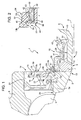
- reference numeral 1 ( figure 1 ) globally denotes a static sealing device for a wheel hub 3 having axis A of rotation and of symmetry.
- the wheel hub 3 comprises an inner ring 5 which is operatively associated with a constant velocity joint 6, only partially shown for the sake of simplicity, for rotating integrally therewith.
- the wheel hub assembly 3 further comprises an outer ring 8 mounted coaxial and concentric with ring 5, radially on the outside of ring 5, and a plurality of rolling bodies 9 arranged between rings 5 and 8.
- the inner ring 5 comprises a so-called “insert" ring 5a, made as an independent element axially locked by a rolled edge 7 and externally delimited by a cylindrical outer lateral surface 26, while the constant velocity joint 6 comprises an outer ring 10 provided with a cylindrical outer lateral surface 29 and with a front toothing 12 which engages with a similar front toothing, not shown for the sake of simplicity, obtained on the edge 7 on reciprocally adjacent portions 13 ( figure 1 ) of the rings 5 and 10.
- the device 1 comprises a first sealing assembly 14 arranged between the inner ring 5 (in particular ring 5a) and the outer ring 8 to protect the rolling bodies 9, and a second sealing assembly 15 integrally restrained, as shall be seen, to the inner ring 5 (in particular the ring 5a), arranged between the wheel hub 3 and the outer ring 10 of the joint 6, partially fitted on the surface 29.
- the sealing assemblies 14 and 15 are symmetrical and coaxial with respect to axis A.
- the sealing assembly 14 comprises: two shields 16 and 21 arranged facing each other and fitted on the inner ring 5 (in particular 5a) and onto the inner ring 8, respectively; and a plurality of annular lips 22, 23 integral with the shield 21 and arranged in sliding contact with the shield 16.
- the shield 16 is L-shaped in radial section and in turn comprises a sleeve portion 17 anchored/fitted by interference and therefore, fluid-sealingly, onto the radially outer lateral surface 26 of the inner ring 5, and a flange portion 18, which radially extends so as to protrude on the outside from the sleeve portion 17 and towards the outer ring 8.
- the flange portion 18 supports an annular signal generating element 19 defined by a flat annular insert 19b, having predetermined thickness measured in axial direction, of a magnetizable elastomeric material which has been magnetized and anchored to the frontal surface 20 so as to wholly cover it.
- the annular insert 19b has either a plurality of magnetized and non magnetized zones alternating with each other about axis A, or a plurality of magnetized zones with opposite polarity; once the annular element or insert 19b is operatively coupled with a sensor, known and not shown for the sake of simplicity, such sensor emits a signal function of the rotation speed of ring 5.
- the flange portion 18 carries a tubular support element 24 which axially projects so as to protrude from the flange portion 18 and, in use, from the inner ring 5 (in particular 5a).
- the tubular element 24 is arranged substantially flushed with the sleeve portion 17 of the shield 16 and therefore, substantially flushed with the radially outer cylindrical lateral surface 26 of the inner ring 5.
- the second sealing assembly 15 comprises a tubular core 28, opposite ends 27, 30 of which are at least partially embedded in an elastomeric material forming, at the first end 27 facing the side opposite to the first sealing assembly 14, at least one annular sealing lip 31 sealingly cooperating with the outer ring 10 of the joint 6; and, at the second end 29 facing the first sealing assembly 14, an elastically deformable annular tooth 32 for coupling to the tubular element 24.
- the tubular support element 24 has, on the side of a radially inner lateral surface 33 thereof, a shape complementary to that of tooth 32 so as to snappingly receive it therein, to axially restrain in a protruding manner the second sealing assembly 15 to the first sealing assembly 14 and therefore to the inner ring 5 of the wheel hub 3.
- the tooth 32 of elastomeric material wherein the second end 30 of the core 15 is embedded and the inner lateral surface 33 of the tubular element 24 are shaped so that in use, the tooth 32 frontally abuts against the inner ring 5 (in particular against the ring 5a), substantially in correspondence with the radially outer lateral surface 26.
- the tubular support element 24 consists of a tubular sleeve 34 made of an elastomeric material, which axially projects so as to protrude from the annular signal generating element 19.
- the sleeve 34 is obtained integral with the annular signal generating element 19, therefore integral with the insert 19b of elastomeric material, through which the tubular support element 24 defined by the sleeve 34 is anchored integral to the flange portion 18.
- the tubular sleeve 34 made of elastomeric material forming the tubular support element 24 has a thickness, measured in the radial direction, which is substantially equal to the thickness of the sleeve portion 17 of the shield 16, so as to form a protruding extension thereof on the side of the frontal surface 20.
- the flange portion 18 of the shield 16 may have, substantially at the sleeve portion 17, an annular bulge 35 defined by a U-shaped fold of the flange portion 18, and extending with the convexity thereof towards the tubular support sleeve 34; it therefore has the concavity thereof facing shield 21.
- the radially inner lateral surface 33 of sleeve 34 ( figure 2 ) is provided, at a first end 37 thereof closer to the flange portion 18, with an annular indentation 38 obtained substantially flushed with, but on a side opposite to, a frontal outer surface 39 of the annular signal generating element 19, arranged parallel to the frontal surface 20.
- the annular indentation 38 creates, on one side, a preferential radial bending zone on the tubular support element 24 corresponding to a thinned root portion 40 of the protruding sleeve 34, which directly originates from the insert 19b, and on the other side it creates an annular receiving seat for the elastically deformable tooth 32, consisting of the indentation 38 itself.
- the lateral surface 33 is also provided with an annular rim 42 obtained at one second end 43 thereof, opposite to the first end 37; the rim 42 extends to a position which is immediately adjacent to the indentation 38 and has, in the radial section, a convex curved profile which is seamlessly joined to a corresponding concave curved profile of the indentation 38, whereby the lateral surface 33 has a substantially upturned S profile in radial section.
- the profile of the annular rim 42 defines, on the side opposite to the flange portion 18 and therefore at the end 43, an inlet opening 44 of the tubular element 24 ( figure 2 ) flared towards the joint 6, adapted to define an invitation for the insertion in the sleeve 34 of the tooth 32 of elastomeric material of the second sealing assembly 15.
- tooth 32 of elastomeric material is delimited towards the first sealing assembly 14 by a front flat surface 45 arranged perpendicularly to the longitudinal symmetry axis A of the device 1 and adapted to abuttingly couple, with the tooth 32 engaged in the indentation 38, with the frontal end surface of the ring 5 (in particular ring 5a), which thus forms an axial support shoulder 48 for the tooth 32, a shoulder that is integral with the flange portion 18.
- the tooth 32 is shaped so as to partially project, on the side of the surface 45, axially protruding from the second end 30 of the tubular core 15, so as to improve its elastic deformability in the coupling step, without impairing the coupling sturdiness, once the same coupling has been made.
- the end 30 of the core 15 is delimited towards the tooth 32 by a frustoconical annular surface 46 which, when the first sealing assembly 14 and the second sealing assembly 15 are coupled, is substantially tangent to the flared inlet opening 44 of the tubular support element 24.
- the core 28 is provided, substantially at the centre between the ends 27 and 30, with a step-shaped portion 41, obtained by an L-fold of the tubular core 28.
- the sealing assembly 15 is provided, in addition to the elastically deformable sliding sealing lip 31, with a second lip 47 shaped so as to be relatively stiff and which extends slanting so as to protrude from the end 27 on the side opposite to the lip 31, so as to form in use a centrifugation element for any contaminants that approach the lip 31.
- the sealing assembly 15 may be made as an element independent of the sealing assembly 14 and in particular, of the shield 16, although being in use integrally retrained to the shield 16, axially protruding from the shield 16, as if obtained integrally therewith, above all by a simple snapping coupling, facilitated by the described shape of the rim 42.
- the device 1 may be mounted in two steps; by first mounting only the sealing assembly 14 between the rings 5 and 8, before carrying out the plastic deformation of the edge 7; in this way, the rolling bodies 9 are protected during all the processing steps of the wheel hub assembly 3/constant velocity joint 6; thereafter, by snappingly coupling the sealing assembly 15, after having fitted it on the side of the end 27 on surface 29, with the elastomeric sleeve 34 integrally carried by the shield 16.
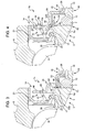
- figure 4 shows a possible version 1b of the static sealing device in figure 1 . Details similar or equal to those already described are indicated with the same reference numerals for the sake of simplicity.
- the device 1b is identical to the device 1 described above, except in that it has a tooth 32b obtained so as to radially project protruding on the inside of the tubular core 28 (rather than on the outside), and in that the surface of the elastomeric sleeve 34 defining the tubular support element 24 according to the invention, adapted to couple with the tooth 32b, is a radially outer lateral surface 50 of the sleeve 34, rather than being the radially inner lateral surface 33, as in the case above.
- the profile of the surface 50 and of the tooth 32b are those described above for the surface 33 and the tooth 32, i.e. those in figure 2 , but of course they are reversed by 180° with respect to axis A.
- the axial shoulder 48 for the tooth 32b is defined by the flange portion 18, rather than by the ring 5.
- FIG 3 shows a version 1c of the static sealing device according to the invention, to be used if a signal generating element 19 is not required.
- the second sealing assembly 15 is identical to that described for the device 1 of figures 1 and 2 and has a tooth 32 for engaging with the tubular support element 24.
- the latter rather than consisting of a sleeve of elastomeric material as 34, consists of an annular bulged portion 49 of the first shield 16 defined by a U-shaped fold, in radial section, made at least on the flange portion 18 in order to axially project so as to protrude from the flange portion 18 on the side opposite to the sleeve portion 1; such U-shaped fold has the concavity facing the sleeve portion 17 and one of the opposite sides thereof, in particular the radially innermost one, defines a radially inner lateral surface 33b of the tubular element 24 having a shape complementary to the shape of the elastically deformable coupling tooth 32 carried by the tubular core 28.
- the profile of the surface 33b is substantially identical to that described above for the surface 33 and in the practice is obtained by plastically deforming also a part of the sleeve portion 17 immediately adjacent to the flange portion 18; of course, moreover, according to this version, the sleeve portion 17 of the shield 16 has an axial length greater than that of the ring 5 (5a), so as to protrudingly project from the same, in use, on the side of the flange portion 18.
- both embodiments of the invention shown in figures 1 and 4 may also be carried out without the signal generating element 19, anchoring the elastomeric sleeve 32 or 32b directly onto the frontal surface or face 20 of the flange portion 18, also without the annular insert 19b, which may be totally lacking or only partially cover the face or surface 20 and in any case be obtained from a normal, non-magnetizable elastomeric material.
Landscapes
- Engineering & Computer Science (AREA)
- General Engineering & Computer Science (AREA)
- Mechanical Engineering (AREA)
- Sealing Of Bearings (AREA)
- Gasket Seals (AREA)
- Rolling Contact Bearings (AREA)
Claims (12)
- Statische Dichtvorrichtung (1) für Radnaben (3), die mit Gleichlaufgelenken (6) verbunden sind, wobei die Vorrichtung eine erste Dichtbaugruppe (14) umfasst, die bei Verwendung zwischen einem Außenring (8) und einer radialen, zylindrischen Außenseitenoberfläche (26) eines Innenrings (5) der Radnabe (3) angeordnet ist, und eine zweite Dichtbaugruppe (15), die bei Verwendung zwischen der Radnabe (3) und einem Außenring (10) des Gleichlaufgelenks angeordnet ist;
wobei die erste Dichtbaugruppe (14) eine erste Abschirmung (16) umfasst, die mit dem Innenring (5) mittels eines Hülsenabschnitts (17) verankert ist, der auf der radialen , zylindrischen Außenseitenoberfläche (26) sitzt und auf der Seite des Gelenks (6) mit einem Flanschabschnitt (18) bereitgestellt ist, der sich radial erstreckt, sodass er aus dem Hülsenabschnitt (17) und in Richtung des Außenrings (8) der Radnabe (3) hervorsteht;
dadurch gekennzeichnet, dass, in Kombination:
die erste Dichtbaugruppe (14) ein rohrförmiges Trägerelement (24) umfasst, das axial vorsteht, um bei Verwendung aus dem Flanschabschnitt (18) und dem Innenring (5) vorzustehen; und
die zweite Dichtbaugruppe (15) einen rohrförmigen Kern (28) mit ersten und zweiten gegenüberliegenden Enden (27, 30), die mindestens teilweise in ein Elastomermaterial eingebettet sind und am ersten Ende (27), das der Seite gegenüber der ersten Dichtbaugruppe (14) zugewandt ist, mindestens eine ringförmige Dichtlippe (31) bildet, die dichtend mit dem Außenring (10) des Gelenks (6) zusammenwirkt; und
am zweiten Ende (30), das der ersten Dichtbaugruppe (14) zugewandt ist, einen elastisch verformbaren ringförmigen Zahn (32) zum Koppeln mit dem rohrförmigen Trägerelement(24) umfasst;- wobei das rohrförmige Trägerelement (24) auf der Seite einer Seitenoberfläche (33) davon eine Form aufweist, welche die Form des Zahns (32) ergänzt, um den Zahn (32) federnd aufzunehmen und die zweite Dichtbaugruppe (15) axial an der ersten Dichtbaugruppe (14) und so während der Verwendung am Innenring (5) der Radnabe zu halten. - Dichtvorrichtung (1) nach Anspruch 1, dadurch gekennzeichnet, dass der Zahn (32), der aus Elastomermaterial hergestellt ist, in dem das zweite Ende (30) des rohrförmigen Kerns (28) der zweiten Dichtbaugruppe (15) eingebettet ist, und die Seitenoberfläche (33) des rohrförmigen Trägerelements (24) derart geformt sind, dass während der Verwendung der Zahn (32) vorne an einer axialen Schulter anliegt, die einstückig mit dem rohrförmigen Trägerelement ausgebildet ist, und die im Wesentlichen bündig an der Seitenoberfläche des rohrförmigen Trägerelements beginnt.
- Dichtvorrichtung nach Anspruch 2, dadurch gekennzeichnet, dass die axiale Schulter bei der Verwendung entweder durch den Innenring (5) oder durch den Flanschabschnitt (18) der ersten Abschirmung definiert wird, je nachdem, ob die Seitenoberfläche (33) des rohrförmige Trägerelements (24), das eine Form aufweist, welche die Form des elastisch verformbaren Zahns (32) ergänzt, die radiale Innen- oder radiale Außenseitenoberfläche des rohrförmigen Trägerelements (24) ist.
- Dichtvorrichtung nach einem der vorhergehenden Ansprüche, dadurch gekennzeichnet, dass das rohrförmige Trägerelement (24) aus einer rohrförmigen Hülse (34), die aus einem Elastomermaterial hergestellt ist, besteht, das axial vorsteht, um aus dem Flanschabschnitt (18) vorzustehen, an dem es einstückig gehalten wird, und das im Wesentlichen bündig mit dem Hülsenabschnitt (17) angeordnet ist und daher im Wesentlichen bündig mit der radialen, zylindrischen Außenseitenoberfläche (26) des Innenrings (5) abschließt.
- Dichtvorrichtung nach Anspruch 4, dadurch gekennzeichnet, dass der Flanschabschnitt (18) der ersten Abschirmung (16) ein ringförmiges signalerzeugendes Element (19) nach außen und zu dem Gelenk (6) trägt, das aus einem Einsatz (19b) mit vorbestimmter Dicke besteht, die in axialer Richtung gemessen wird, und aus einem magnetisierbaren Elastomermaterial hergestellt ist, das mit einer ersten vorderen Oberfläche (20) des Flanschabschnitts der ersten Abschirmung (16) verankert wurde, die dem Gleichlaufgelenk (6) zugewandt ist, um dieses vollständig zu bedecken; wobei das rohrförmige Trägerelement (24), das aus einer rohrförmigen Hülse (34), die aus einem Elastomermaterial hergestellt ist, das einstückig mit dem ringförmigen signalerzeugenden Element (19) erhalten wird, besteht, über welches das rohrförmige Trägerelement (24) einstückig mit dem Flanschabschnitt (18) der ersten Abschirmung verankert ist.
- Dichtvorrichtung nach Anspruch 4 oder 5, dadurch gekennzeichnet, dass die rohrförmige Hülse (34), die aus Elastomermaterial hergestellt ist, welches das rohrförmige Trägerelement (24) bildet, eine Dicke aufweist, die in radialer Richtung gemessen im Wesentlichen der Dicke des Hülsenabschnitts (17) der ersten Abschirmung (16) entspricht, um so eine vorstehende Erweiterung davon auf der Seite der ersten vorderen Oberfläche (20) des Flanschabschnitts (18), der dem Gelenk (6) während der Verwendung zugewandt ist, zu bilden.
- Vorrichtung nach einem der Ansprüche 4 bis 6, dadurch gekennzeichnet, dass der Flanschabschnitt (18) der ersten Abschirmung (16) der ersten Dichtbaugruppe (14) im Wesentlichen am Hülsenabschnitt (17) einen ringförmigen Wulst (35) aufweist, der von einer U-förmigen Faltung des Flanschabschnitts (18) definiert wird, und sich in Richtung der rohrförmigen Hülse (34), die aus dem Elastomermaterial hergestellt ist, welches das rohrförmige Trägerelement (24) bildet, erstreckt.
- Dichtvorrichtung nach Anspruch 1 oder 2, dadurch gekennzeichnet, dass das rohrförmige Trägerelement (24) aus einem ringförmigen Wulstabschnitt der ersten Abschirmung (16), die von einer U-förmigen Faltung definiert wird, im radialen Abschnitt besteht, der mindestens an dem Flanschabschnitt (18) ausgebildet ist, um axial vorzustehen, um von dem Flanschabschnitt (18) auf der Seite gegenüber des Hülsenabschnitts (17) vorzustehen;
wobei die Konkavität der U-förmigen Faltung dem Hülsenabschnitt (17) zugewandt ist und eine ihrer gegenüberliegenden Seiten die Seitenoberfläche definiert, die eine Form aufweist, welche die Form des elastisch verformbaren Zahns (32) zum Koppeln mit dem rohrförmigen Trägerelement (24) ergänzt. - Dichtvorrichtung nach einem der vorhergehenden Ansprüche, dadurch gekennzeichnet, dass die Seitenoberfläche (33) des rohrförmigen Trägerelements (24) an einem ersten Ende (30) davon bereitgestellt ist, das näher vom Flanschabschnitt (18) der ersten Abschirmung (16) angeordnet ist, wobei eine ringförmige Vertiefung (38) ausgelegt ist, einerseits eine bevorzugte radiale Biegezone (40) an dem rohrförmigen Trägerelement (24) und andererseits einen ringförmigen Aufnahmesitz für den elastisch verformbaren Zahn (32) des zweiten Endes des Kerns (28) der zweiten Dichtbaugruppe herzustellen.
- Dichtvorrichtung nach Anspruch 9, dadurch gekennzeichnet, dass die Seitenoberfläche (33) des rohrförmigen Trägerelements (24) mit einem ringförmigen Rand (42) bereitgestellt ist, der an einem zweiten Ende (43) davon gegenüber dem ersten Ende (30) erhalten wird; wobei sich der Rand (42) zu einer Position erstreckt, die unmittelbar benachbart zu der Vertiefung (38) ist und radialen Abschnitt ein konvex gekrümmtes Profil aufweist, das nahtlos in ein entsprechendes konkaves gekrümmtes Profil der Vertiefung (38) übergeht.
- Vorrichtung nach Anspruch 10, dadurch gekennzeichnet, dass das Profil des ringförmigen Randes (42) auf der Seite gegenüber des Flanschabschnitts (18) der Abschirmung der ersten Dichtbaugruppe eine Einlassöffnung (44) definiert, die in Richtung des Gelenks (6) des rohrförmigen Trägerelements (24) aufgeweitet ist.
- Dichtvorrichtung nach Anspruch 11, dadurch gekennzeichnet, dass der Zahn (32), der aus Elastomermaterial der zweiten Dichtbaugruppe (15) hergestellt ist, in Richtung der ersten Dichtbaugruppe (14) durch eine vordere flache Oberfläche (45) begrenzt wird, die senkrecht zu einer Längssymmetrieachse (A) der Vorrichtung angeordnet ist und axial vorsteht, um teilweise aus dem zweiten Ende (30) des rohrförmigen Kerns (28) vorzustehen, der in Richtung des Zahns (32) von einer ringförmigen, kegelstumpfförmigen Oberfläche (46) begrenzt wird, die, wenn die ersten und zweiten Dichtbaugruppen gekoppelt sind, im Wesentlichen tangential zu der aufgeweiteten Einlassöffnung (44) des rohrförmigen Trägerelements verläuft.
Applications Claiming Priority (1)
| Application Number | Priority Date | Filing Date | Title |
|---|---|---|---|
| IT000573A ITTO20110573A1 (it) | 2011-06-29 | 2011-06-29 | Dispositivo di tenuta statica per gruppi mozzi ruota connessi a giunti omocinetici |
Publications (2)
| Publication Number | Publication Date |
|---|---|
| EP2541108A1 EP2541108A1 (de) | 2013-01-02 |
| EP2541108B1 true EP2541108B1 (de) | 2015-03-04 |
Family
ID=44555433
Family Applications (1)
| Application Number | Title | Priority Date | Filing Date |
|---|---|---|---|
| EP20120172819 Not-in-force EP2541108B1 (de) | 2011-06-29 | 2012-06-20 | Statische Dichtvorrichtung für an Gleichlaufgelenke befestigte Radnabenbaugruppen |
Country Status (6)
| Country | Link |
|---|---|
| US (1) | US9488278B2 (de) |
| EP (1) | EP2541108B1 (de) |
| JP (1) | JP2013011346A (de) |
| KR (1) | KR20130002933A (de) |
| CN (1) | CN102852978B (de) |
| IT (1) | ITTO20110573A1 (de) |
Cited By (2)
| Publication number | Priority date | Publication date | Assignee | Title |
|---|---|---|---|---|
| DE102024106309A1 (de) | 2024-03-05 | 2024-05-23 | Audi Aktiengesellschaft | Radträgeranordnung für ein Kraftfahrzeug sowie Verfahren zum Herstellen einer solchen Radträgeranordnung |
| DE102018118880B4 (de) * | 2018-08-03 | 2025-05-28 | Schaeffler Technologies AG & Co. KG | Dichtungsanordnung eines Radlagers |
Families Citing this family (11)
| Publication number | Priority date | Publication date | Assignee | Title |
|---|---|---|---|---|
| US9464720B2 (en) * | 2006-03-20 | 2016-10-11 | Aktiebolaget Skf | Annular sealing assembly, in particular for wheel hubs |
| ITTO20130507A1 (it) | 2013-06-19 | 2014-12-20 | Skf Ab | Dispositivo flessibile di tenuta per gruppi mozzi ruota connessi a giunti omocinetici |
| DE102014210732A1 (de) * | 2014-06-05 | 2015-12-17 | Schaeffler Technologies AG & Co. KG | Lageranordnung, umfassend einem optimierten Dichtring mit Dichtelement |
| US10415642B2 (en) * | 2015-06-09 | 2019-09-17 | Aktiebolaget Skf | Coupling system of a sealing assembly with a rotating annular element |
| WO2017076402A1 (de) * | 2015-11-02 | 2017-05-11 | Schaeffler Technologies AG & Co. KG | Radlagereinheit |
| DE102016214499A1 (de) * | 2016-08-05 | 2017-08-17 | Schaeffler Technologies AG & Co. KG | Dichtungsanordnung |
| US11420467B2 (en) | 2018-09-10 | 2022-08-23 | Aktiebolaget Skf | Low-friction sealing device for wheel hub assemblies connected to constant-velocity joints |
| DE102018220346A1 (de) * | 2018-11-27 | 2020-05-28 | Aktiebolaget Skf | Lagerdichtung |
| US12516735B2 (en) | 2023-03-03 | 2026-01-06 | Federal-Mogul Powertrain Llc | PTFE shaft seal and method of making |
| KR102879528B1 (ko) * | 2023-05-19 | 2025-11-03 | 주식회사 일진글로벌 | 차량용 휠베어링 |
| DE102024103459A1 (de) * | 2024-02-08 | 2025-08-14 | Schaeffler Technologies AG & Co. KG | Radlagerungsvorrichtung aufweisend Schnittstellendichtung mit verkürztem Metallblech und optimiertem Dichtlippenabschnitt |
Family Cites Families (12)
| Publication number | Priority date | Publication date | Assignee | Title |
|---|---|---|---|---|
| US4960335A (en) * | 1989-11-13 | 1990-10-02 | The Timken Company | Unitary enclosure and cover therefor |
| US6637754B1 (en) * | 1999-11-17 | 2003-10-28 | Ntn Corporation | Wheel bearing and sealing device therefor |
| DE10302069A1 (de) * | 2003-01-21 | 2004-07-29 | Ina-Schaeffler Kg | Dichtungsbaugruppe für eine Lagerbüchse |
| JP2004345370A (ja) * | 2003-05-20 | 2004-12-09 | Nsk Ltd | 車輪駆動用転がり軸受ユニット |
| DE102006032159A1 (de) * | 2006-07-12 | 2008-01-24 | Schaeffler Kg | Lageranordnung einer über ein Drehgelenk antreibbaren Radnabe eines Kraftfahrzeuges |
| US8210752B2 (en) * | 2007-09-26 | 2012-07-03 | Jtekt Corporation | Wheel supporting device |
| CN101827715B (zh) * | 2007-10-15 | 2014-05-21 | Ntn株式会社 | 车轮用轴承装置 |
| ATE543661T1 (de) | 2008-05-19 | 2012-02-15 | Gkn Driveline Deutschland Gmbh | Eine radnabe und ein gleichlaufdrehgelenk umfassende vorrichtung |
| WO2009147845A1 (ja) * | 2008-06-04 | 2009-12-10 | Ntn株式会社 | 駆動車輪用軸受装置 |
| JP5355938B2 (ja) * | 2008-06-09 | 2013-11-27 | Ntn株式会社 | 駆動車輪用軸受装置 |
| JP5331385B2 (ja) * | 2008-06-04 | 2013-10-30 | Ntn株式会社 | 駆動車輪用軸受装置 |
| DE102008050127A1 (de) * | 2008-10-06 | 2010-04-08 | Schaeffler Kg | Vorrichtung zur axialen Fixierung |
-
2011
- 2011-06-29 IT IT000573A patent/ITTO20110573A1/it unknown
-
2012
- 2012-06-14 KR KR20120063603A patent/KR20130002933A/ko not_active Withdrawn
- 2012-06-18 JP JP2012136667A patent/JP2013011346A/ja active Pending
- 2012-06-19 US US13/526,617 patent/US9488278B2/en not_active Expired - Fee Related
- 2012-06-20 EP EP20120172819 patent/EP2541108B1/de not_active Not-in-force
- 2012-06-27 CN CN201210216946.2A patent/CN102852978B/zh not_active Expired - Fee Related
Cited By (3)
| Publication number | Priority date | Publication date | Assignee | Title |
|---|---|---|---|---|
| DE102018118880B4 (de) * | 2018-08-03 | 2025-05-28 | Schaeffler Technologies AG & Co. KG | Dichtungsanordnung eines Radlagers |
| DE102024106309A1 (de) | 2024-03-05 | 2024-05-23 | Audi Aktiengesellschaft | Radträgeranordnung für ein Kraftfahrzeug sowie Verfahren zum Herstellen einer solchen Radträgeranordnung |
| EP4614021A1 (de) | 2024-03-05 | 2025-09-10 | Audi Ag | Radträgeranordnung für ein kraftfahrzeug sowie verfahren zum herstellen einer solchen radträgeranordnung |
Also Published As
| Publication number | Publication date |
|---|---|
| CN102852978A (zh) | 2013-01-02 |
| US9488278B2 (en) | 2016-11-08 |
| US20130001885A1 (en) | 2013-01-03 |
| ITTO20110573A1 (it) | 2012-12-30 |
| JP2013011346A (ja) | 2013-01-17 |
| CN102852978B (zh) | 2017-03-01 |
| EP2541108A1 (de) | 2013-01-02 |
| KR20130002933A (ko) | 2013-01-08 |
Similar Documents
| Publication | Publication Date | Title |
|---|---|---|
| EP2541108B1 (de) | Statische Dichtvorrichtung für an Gleichlaufgelenke befestigte Radnabenbaugruppen | |
| EP2541107B1 (de) | Statische Dichtvorrichtung für an Gleichlaufgelenke befestigte Radnabenbaugruppen | |
| EP2815891B1 (de) | Anordnung einer mit einem Gleichlaufgelenk mit einer flexiblen Dichtungsvorrichtung verbundenen Radnabe | |
| EP2103451B1 (de) | Radstützvorrichtung | |
| EP2816248B1 (de) | Anordnung einer mit einem Gleichlaufgelenk mit einer reibungsarmen Dichtungsvorrichtung verbundenen Radnabe | |
| CN105605095B (zh) | 带编码装置的车轮支撑用滚动轴承单元 | |
| EP2815892B1 (de) | Anordnung einer mit einem Gleichlaufgelenk mit einer Dichtungsvorrichtung verbundenen Radnabe | |
| US9701159B2 (en) | Low friction sealing device for a wheel hub assembly connected to a constant velocity joint | |
| US20110206312A1 (en) | Endcap for wheel bearing assembly | |
| JP4158341B2 (ja) | 軸受装置 | |
| JP4333116B2 (ja) | 転がり軸受の密封装置 | |
| KR102595375B1 (ko) | 드라이브 액슬 조립체 | |
| CN102848852B (zh) | 用于连接到等速万向节的轮毂组件的静态密封装置 | |
| KR20190132184A (ko) | 휠 베어링 조립체 | |
| JP5376411B2 (ja) | 転がり軸受装置 | |
| JP2005121669A (ja) | トーンホイール付転がり軸受ユニット | |
| JP2007232150A (ja) | エンコーダ付きシール及び軸受ユニット |
Legal Events
| Date | Code | Title | Description |
|---|---|---|---|
| PUAI | Public reference made under article 153(3) epc to a published international application that has entered the european phase |
Free format text: ORIGINAL CODE: 0009012 |
|
| AK | Designated contracting states |
Kind code of ref document: A1 Designated state(s): AL AT BE BG CH CY CZ DE DK EE ES FI FR GB GR HR HU IE IS IT LI LT LU LV MC MK MT NL NO PL PT RO RS SE SI SK SM TR |
|
| AX | Request for extension of the european patent |
Extension state: BA ME |
|
| 17P | Request for examination filed |
Effective date: 20130621 |
|
| RBV | Designated contracting states (corrected) |
Designated state(s): AL AT BE BG CH CY CZ DE DK EE ES FI FR GB GR HR HU IE IS IT LI LT LU LV MC MK MT NL NO PL PT RO RS SE SI SK SM TR |
|
| GRAP | Despatch of communication of intention to grant a patent |
Free format text: ORIGINAL CODE: EPIDOSNIGR1 |
|
| INTG | Intention to grant announced |
Effective date: 20141106 |
|
| GRAS | Grant fee paid |
Free format text: ORIGINAL CODE: EPIDOSNIGR3 |
|
| GRAA | (expected) grant |
Free format text: ORIGINAL CODE: 0009210 |
|
| AK | Designated contracting states |
Kind code of ref document: B1 Designated state(s): AL AT BE BG CH CY CZ DE DK EE ES FI FR GB GR HR HU IE IS IT LI LT LU LV MC MK MT NL NO PL PT RO RS SE SI SK SM TR |
|
| REG | Reference to a national code |
Ref country code: GB Ref legal event code: FG4D |
|
| REG | Reference to a national code |
Ref country code: CH Ref legal event code: EP |
|
| REG | Reference to a national code |
Ref country code: IE Ref legal event code: FG4D |
|
| REG | Reference to a national code |
Ref country code: AT Ref legal event code: REF Ref document number: 714193 Country of ref document: AT Kind code of ref document: T Effective date: 20150415 |
|
| REG | Reference to a national code |
Ref country code: DE Ref legal event code: R096 Ref document number: 602012005491 Country of ref document: DE Effective date: 20150416 |
|
| REG | Reference to a national code |
Ref country code: SE Ref legal event code: TRGR |
|
| REG | Reference to a national code |
Ref country code: FR Ref legal event code: PLFP Year of fee payment: 4 |
|
| REG | Reference to a national code |
Ref country code: AT Ref legal event code: MK05 Ref document number: 714193 Country of ref document: AT Kind code of ref document: T Effective date: 20150304 Ref country code: NL Ref legal event code: VDEP Effective date: 20150304 |
|
| PG25 | Lapsed in a contracting state [announced via postgrant information from national office to epo] |
Ref country code: ES Free format text: LAPSE BECAUSE OF FAILURE TO SUBMIT A TRANSLATION OF THE DESCRIPTION OR TO PAY THE FEE WITHIN THE PRESCRIBED TIME-LIMIT Effective date: 20150304 Ref country code: NO Free format text: LAPSE BECAUSE OF FAILURE TO SUBMIT A TRANSLATION OF THE DESCRIPTION OR TO PAY THE FEE WITHIN THE PRESCRIBED TIME-LIMIT Effective date: 20150604 Ref country code: FI Free format text: LAPSE BECAUSE OF FAILURE TO SUBMIT A TRANSLATION OF THE DESCRIPTION OR TO PAY THE FEE WITHIN THE PRESCRIBED TIME-LIMIT Effective date: 20150304 Ref country code: LT Free format text: LAPSE BECAUSE OF FAILURE TO SUBMIT A TRANSLATION OF THE DESCRIPTION OR TO PAY THE FEE WITHIN THE PRESCRIBED TIME-LIMIT Effective date: 20150304 Ref country code: HR Free format text: LAPSE BECAUSE OF FAILURE TO SUBMIT A TRANSLATION OF THE DESCRIPTION OR TO PAY THE FEE WITHIN THE PRESCRIBED TIME-LIMIT Effective date: 20150304 |
|
| REG | Reference to a national code |
Ref country code: LT Ref legal event code: MG4D |
|
| PG25 | Lapsed in a contracting state [announced via postgrant information from national office to epo] |
Ref country code: LV Free format text: LAPSE BECAUSE OF FAILURE TO SUBMIT A TRANSLATION OF THE DESCRIPTION OR TO PAY THE FEE WITHIN THE PRESCRIBED TIME-LIMIT Effective date: 20150304 Ref country code: RS Free format text: LAPSE BECAUSE OF FAILURE TO SUBMIT A TRANSLATION OF THE DESCRIPTION OR TO PAY THE FEE WITHIN THE PRESCRIBED TIME-LIMIT Effective date: 20150304 Ref country code: GR Free format text: LAPSE BECAUSE OF FAILURE TO SUBMIT A TRANSLATION OF THE DESCRIPTION OR TO PAY THE FEE WITHIN THE PRESCRIBED TIME-LIMIT Effective date: 20150605 Ref country code: AT Free format text: LAPSE BECAUSE OF FAILURE TO SUBMIT A TRANSLATION OF THE DESCRIPTION OR TO PAY THE FEE WITHIN THE PRESCRIBED TIME-LIMIT Effective date: 20150304 |
|
| PG25 | Lapsed in a contracting state [announced via postgrant information from national office to epo] |
Ref country code: NL Free format text: LAPSE BECAUSE OF FAILURE TO SUBMIT A TRANSLATION OF THE DESCRIPTION OR TO PAY THE FEE WITHIN THE PRESCRIBED TIME-LIMIT Effective date: 20150304 |
|
| PG25 | Lapsed in a contracting state [announced via postgrant information from national office to epo] |
Ref country code: PT Free format text: LAPSE BECAUSE OF FAILURE TO SUBMIT A TRANSLATION OF THE DESCRIPTION OR TO PAY THE FEE WITHIN THE PRESCRIBED TIME-LIMIT Effective date: 20150706 Ref country code: CZ Free format text: LAPSE BECAUSE OF FAILURE TO SUBMIT A TRANSLATION OF THE DESCRIPTION OR TO PAY THE FEE WITHIN THE PRESCRIBED TIME-LIMIT Effective date: 20150304 Ref country code: RO Free format text: LAPSE BECAUSE OF FAILURE TO SUBMIT A TRANSLATION OF THE DESCRIPTION OR TO PAY THE FEE WITHIN THE PRESCRIBED TIME-LIMIT Effective date: 20150304 Ref country code: SK Free format text: LAPSE BECAUSE OF FAILURE TO SUBMIT A TRANSLATION OF THE DESCRIPTION OR TO PAY THE FEE WITHIN THE PRESCRIBED TIME-LIMIT Effective date: 20150304 Ref country code: EE Free format text: LAPSE BECAUSE OF FAILURE TO SUBMIT A TRANSLATION OF THE DESCRIPTION OR TO PAY THE FEE WITHIN THE PRESCRIBED TIME-LIMIT Effective date: 20150304 |
|
| PG25 | Lapsed in a contracting state [announced via postgrant information from national office to epo] |
Ref country code: IS Free format text: LAPSE BECAUSE OF FAILURE TO SUBMIT A TRANSLATION OF THE DESCRIPTION OR TO PAY THE FEE WITHIN THE PRESCRIBED TIME-LIMIT Effective date: 20150704 Ref country code: PL Free format text: LAPSE BECAUSE OF FAILURE TO SUBMIT A TRANSLATION OF THE DESCRIPTION OR TO PAY THE FEE WITHIN THE PRESCRIBED TIME-LIMIT Effective date: 20150304 |
|
| PGFP | Annual fee paid to national office [announced via postgrant information from national office to epo] |
Ref country code: SE Payment date: 20150630 Year of fee payment: 4 Ref country code: FR Payment date: 20150630 Year of fee payment: 4 |
|
| REG | Reference to a national code |
Ref country code: DE Ref legal event code: R097 Ref document number: 602012005491 Country of ref document: DE |
|
| PLBE | No opposition filed within time limit |
Free format text: ORIGINAL CODE: 0009261 |
|
| STAA | Information on the status of an ep patent application or granted ep patent |
Free format text: STATUS: NO OPPOSITION FILED WITHIN TIME LIMIT |
|
| PG25 | Lapsed in a contracting state [announced via postgrant information from national office to epo] |
Ref country code: MC Free format text: LAPSE BECAUSE OF FAILURE TO SUBMIT A TRANSLATION OF THE DESCRIPTION OR TO PAY THE FEE WITHIN THE PRESCRIBED TIME-LIMIT Effective date: 20150304 Ref country code: DK Free format text: LAPSE BECAUSE OF FAILURE TO SUBMIT A TRANSLATION OF THE DESCRIPTION OR TO PAY THE FEE WITHIN THE PRESCRIBED TIME-LIMIT Effective date: 20150304 |
|
| REG | Reference to a national code |
Ref country code: CH Ref legal event code: PL |
|
| 26N | No opposition filed |
Effective date: 20151207 |
|
| PG25 | Lapsed in a contracting state [announced via postgrant information from national office to epo] |
Ref country code: SI Free format text: LAPSE BECAUSE OF FAILURE TO SUBMIT A TRANSLATION OF THE DESCRIPTION OR TO PAY THE FEE WITHIN THE PRESCRIBED TIME-LIMIT Effective date: 20150304 Ref country code: LU Free format text: LAPSE BECAUSE OF FAILURE TO SUBMIT A TRANSLATION OF THE DESCRIPTION OR TO PAY THE FEE WITHIN THE PRESCRIBED TIME-LIMIT Effective date: 20150620 |
|
| REG | Reference to a national code |
Ref country code: IE Ref legal event code: MM4A |
|
| PG25 | Lapsed in a contracting state [announced via postgrant information from national office to epo] |
Ref country code: IE Free format text: LAPSE BECAUSE OF NON-PAYMENT OF DUE FEES Effective date: 20150620 Ref country code: LI Free format text: LAPSE BECAUSE OF NON-PAYMENT OF DUE FEES Effective date: 20150630 Ref country code: CH Free format text: LAPSE BECAUSE OF NON-PAYMENT OF DUE FEES Effective date: 20150630 |
|
| PG25 | Lapsed in a contracting state [announced via postgrant information from national office to epo] |
Ref country code: BE Free format text: LAPSE BECAUSE OF FAILURE TO SUBMIT A TRANSLATION OF THE DESCRIPTION OR TO PAY THE FEE WITHIN THE PRESCRIBED TIME-LIMIT Effective date: 20150304 |
|
| PG25 | Lapsed in a contracting state [announced via postgrant information from national office to epo] |
Ref country code: MT Free format text: LAPSE BECAUSE OF FAILURE TO SUBMIT A TRANSLATION OF THE DESCRIPTION OR TO PAY THE FEE WITHIN THE PRESCRIBED TIME-LIMIT Effective date: 20150304 |
|
| REG | Reference to a national code |
Ref country code: SE Ref legal event code: EUG |
|
| PG25 | Lapsed in a contracting state [announced via postgrant information from national office to epo] |
Ref country code: SE Free format text: LAPSE BECAUSE OF NON-PAYMENT OF DUE FEES Effective date: 20160621 |
|
| PGFP | Annual fee paid to national office [announced via postgrant information from national office to epo] |
Ref country code: IT Payment date: 20150630 Year of fee payment: 4 |
|
| GBPC | Gb: european patent ceased through non-payment of renewal fee |
Effective date: 20160620 |
|
| REG | Reference to a national code |
Ref country code: FR Ref legal event code: ST Effective date: 20170228 |
|
| PG25 | Lapsed in a contracting state [announced via postgrant information from national office to epo] |
Ref country code: FR Free format text: LAPSE BECAUSE OF NON-PAYMENT OF DUE FEES Effective date: 20160630 |
|
| PG25 | Lapsed in a contracting state [announced via postgrant information from national office to epo] |
Ref country code: SM Free format text: LAPSE BECAUSE OF FAILURE TO SUBMIT A TRANSLATION OF THE DESCRIPTION OR TO PAY THE FEE WITHIN THE PRESCRIBED TIME-LIMIT Effective date: 20150304 Ref country code: BG Free format text: LAPSE BECAUSE OF FAILURE TO SUBMIT A TRANSLATION OF THE DESCRIPTION OR TO PAY THE FEE WITHIN THE PRESCRIBED TIME-LIMIT Effective date: 20150304 Ref country code: HU Free format text: LAPSE BECAUSE OF FAILURE TO SUBMIT A TRANSLATION OF THE DESCRIPTION OR TO PAY THE FEE WITHIN THE PRESCRIBED TIME-LIMIT; INVALID AB INITIO Effective date: 20120620 Ref country code: GB Free format text: LAPSE BECAUSE OF NON-PAYMENT OF DUE FEES Effective date: 20160620 |
|
| PG25 | Lapsed in a contracting state [announced via postgrant information from national office to epo] |
Ref country code: CY Free format text: LAPSE BECAUSE OF FAILURE TO SUBMIT A TRANSLATION OF THE DESCRIPTION OR TO PAY THE FEE WITHIN THE PRESCRIBED TIME-LIMIT Effective date: 20150304 Ref country code: IT Free format text: LAPSE BECAUSE OF NON-PAYMENT OF DUE FEES Effective date: 20160620 |
|
| PG25 | Lapsed in a contracting state [announced via postgrant information from national office to epo] |
Ref country code: TR Free format text: LAPSE BECAUSE OF FAILURE TO SUBMIT A TRANSLATION OF THE DESCRIPTION OR TO PAY THE FEE WITHIN THE PRESCRIBED TIME-LIMIT Effective date: 20150304 |
|
| PG25 | Lapsed in a contracting state [announced via postgrant information from national office to epo] |
Ref country code: MK Free format text: LAPSE BECAUSE OF FAILURE TO SUBMIT A TRANSLATION OF THE DESCRIPTION OR TO PAY THE FEE WITHIN THE PRESCRIBED TIME-LIMIT Effective date: 20150304 |
|
| PG25 | Lapsed in a contracting state [announced via postgrant information from national office to epo] |
Ref country code: AL Free format text: LAPSE BECAUSE OF FAILURE TO SUBMIT A TRANSLATION OF THE DESCRIPTION OR TO PAY THE FEE WITHIN THE PRESCRIBED TIME-LIMIT Effective date: 20150304 |
|
| PGFP | Annual fee paid to national office [announced via postgrant information from national office to epo] |
Ref country code: DE Payment date: 20220628 Year of fee payment: 11 |
|
| P01 | Opt-out of the competence of the unified patent court (upc) registered |
Effective date: 20230513 |
|
| REG | Reference to a national code |
Ref country code: DE Ref legal event code: R119 Ref document number: 602012005491 Country of ref document: DE |
|
| PG25 | Lapsed in a contracting state [announced via postgrant information from national office to epo] |
Ref country code: DE Free format text: LAPSE BECAUSE OF NON-PAYMENT OF DUE FEES Effective date: 20240103 |