EP2541103A2 - Zur Minimierung von kombinierter Wärme- und Druckbeanspruchung bei Einschwingvorgängen konfigurierte Düse und Düsenanordnung - Google Patents
Zur Minimierung von kombinierter Wärme- und Druckbeanspruchung bei Einschwingvorgängen konfigurierte Düse und Düsenanordnung Download PDFInfo
- Publication number
- EP2541103A2 EP2541103A2 EP12173693A EP12173693A EP2541103A2 EP 2541103 A2 EP2541103 A2 EP 2541103A2 EP 12173693 A EP12173693 A EP 12173693A EP 12173693 A EP12173693 A EP 12173693A EP 2541103 A2 EP2541103 A2 EP 2541103A2
- Authority
- EP
- European Patent Office
- Prior art keywords
- nozzle
- pressure vessel
- flange
- contour
- radius
- Prior art date
- Legal status (The legal status is an assumption and is not a legal conclusion. Google has not performed a legal analysis and makes no representation as to the accuracy of the status listed.)
- Granted
Links
Images




Classifications
-
- F—MECHANICAL ENGINEERING; LIGHTING; HEATING; WEAPONS; BLASTING
- F16—ENGINEERING ELEMENTS AND UNITS; GENERAL MEASURES FOR PRODUCING AND MAINTAINING EFFECTIVE FUNCTIONING OF MACHINES OR INSTALLATIONS; THERMAL INSULATION IN GENERAL
- F16J—PISTONS; CYLINDERS; SEALINGS
- F16J12/00—Pressure vessels in general
Definitions
- the present invention is generally related to nozzles for use in pressure vessels and is more particularly directed to nozzles wherein portions thereof are contoured to minimize stress.
- Pressure vessels such as, for example, boiler drums are typically subjected to cyclic thermal and mechanical stresses due to changes in internal fluid pressure and temperature. These cyclic stresses can limit the number and/or magnitude of pressure and/or temperature cycles that the pressure vessels can withstand.
- pressure vessels have bores, or penetrations extending through the shell of the pressure vessel.
- Conduits such as pipes are attached to the pressure vessel such that the penetration and the pipes are in fluid communication with one another to allow for the ingress and egress of fluids to and from the pressure vessel.
- Stress concentrations exist at the intersection of the pipe(s) and the shell of the pressure vessel. These stress concentrations result in higher stresses and often become a limiting factor in the design of the pressure vessel for phenomena such as fatigue and/or cracking of the magnetite layer that can form on the metal surface, and which may limit the useful lifetime.
- the present disclosure resides in one aspect in a nozzle assembly for use in a pressure vessel such as a boiler.
- the pressure vessel includes a wall having an inner wall surface that defines an interior area. At least one aperture extends through a thickness defined by the wall.
- a nozzle is positioned in at least one aperture and includes a body portion having a bore extending there through and in communication with the interior area of the pressure vessel.
- the nozzle includes an end portion defined by a radius extending circumferentially around the end portion, the radius being substantially tangent to a contour defined by the inner surface pressure vessel wall.
- the nozzle further comprises an integral flange extending outwardly from the body portion of the nozzle.
- the flange has an outer surface defining a contour substantially tangent to a contour defined by the outer surface of the pressure vessel wall and an inner surface defining a contour substantially tangent to the inner surface of the pressure vessel wall.
- the above-described radius defined by the end portion of the nozzle is substantially tangent to the inner and/or outer surface of the flange and thereby substantially tangent to the contour defined by the inner and/or outer surface of the pressure vessel wall.
- the nozzle can include a flange without an end portion radius.
- the nozzle may also include a second radius extending between the flange and the body portion of the nozzle, with the radius being substantially tangent to a contour of the upper surface defined by the flange.
- the present disclosure sets forth in another aspect, a method for configuring a nozzle assembly for use in a pressure vessel.
- the stresses induced during operation due to pressure and temperature in the pressure vessel are determined using finite element analysis (PEA) or some other appropriate stress analysis method or technique.
- PPA finite element analysis
- the magnitude of stress concentration at an intersection formed between the nozzle and an inner surface of the pressure vessel wall is determined.
- a radius geometry defined by the nozzle is determined. The radius is located such that it is substantially tangent to the interior and/or exterior wall defined by the pressure vessel.
- an integral flange may be included to provide separation between the radius and the junction to the vessel.
- the radius is sized to reduce stress concentrations at the intersection due to cyclic temperature and pressure loads in the interior of the pressure vessel.
- the present disclosure is not limited in this regard as the nozzle can be configured to include a flange without the above-described radius. In either case, the flange is sized based on stress analysis such that the area where the nozzle is welded to the pressure vessel is outside the areas of high stress.
- the pressure vessel is a boiler drum.
- FIG. 1 is a finite element analysis stress contour plot showing a prior art nozzle installed in a pressure vessel subjected to cyclic temperature and pressure loads typically found in a boiler drum used in a heat recovery steam generator.
- FIG. 2 is a finite element analysis stress contour plot showing an embodiment of a nozzle as described herein installed in a pressure vessel subjected to cyclic temperature and pressure loads typically found in a boiler drum used in a heat recovery steam generator.
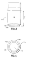
- FIG. 3 is a side elevational view of an embodiment of a nozzle as disclosed herein.
- FIG. 4 is a bottom view of the nozzle of FIG. 3 .
- FIG 5 is a partial cross-sectional view of a nozzle assembly showing the nozzle of FIG. 2 installed in a pressure vessel.
- FIG. 5A is an enlarged partial view of the nozzle assembly of FIG. 2 .
- FIG. 6 is a cross sectional view another embodiment of a nozzle assembly as disclosed herein showing an alternate embodiment of a nozzle installed in a pressure vessel.
- FIG. 7 is a cross sectional view of an alternative embodiment of FIG. 6 .
- the results of a finite element analysis in the form of a stress contour plot of a cut-away view of a portion of a nozzle assembly, are shown and are generally designated by the reference number 10.
- the stress contour plot 10 depicts areas of varying stress, the stress contours being superimposed over a section of a known prior art nozzle assembly generally designated by the reference number 10.
- the nozzle assembly 10 includes a nozzle 14 that extends through an aperture and into an interior area 15 defined by a pressure vessel wall 16. In the illustrated embodiment the area of maximum stress is located at the intersection defined between the nozzle 14 and an interior surface of the pressure vessel wall 16.
- the nozzle 14 includes a cylindrical body portion 18 having a constant diameter along a length "L" that extends to an end portion 20 of the nozzle.
- the nozzle 14 is attached to the pressure vessel 16 via welding. Since the intersection between the interior wall 21 of the pressure vessel 16 and the nozzle body 18 defines a substantially sharp corner, the stress concentration at this point is high. As shown in FIG. 1 , for a particular geometry the maximum stress range induced at the above-described intersection for a given history of temperatures and pressures within the pressure vessel is 592 MPa (Megapascals).
- a nozzle assembly 110 in accordance with the present invention includes a nozzle 114 attached to a pressure vessel 116.
- the nozzle assembly 110 is similar to the nozzle assembly 10. Accordingly, like elements will be assigned like reference numbers preceded by the numeral 1.
- the nozzle 114 best seen in FIGS. 3 and 4 , includes a body portion 118 defined in part by a length L' extending to a bottom portion 120 of the nozzle.
- a bore 119 extends through the nozzle 114 and when the nozzle is installed on the pressure vessel 116, best seen in FIG. 5 , the bore 119 is in communication with the interior area 115 of the pressure vessel.
- the body portion 118 of the nozzle 114 includes a substantially cylindrical portion of substantially constant diameter extending part-way along the length L'. Adjacent to the bottom portion 120 of the nozzle 114, the body portion 118 defines a radius 122. In the illustrated embodiment, the radius 122 is substantially tangent to the inner wall of the pressure vessel 121.
- the nozzle assembly 110 includes an outer radius 142 extending between the nozzle body 118 and an outer surface of the pressure vessel 116. Depending on the nozzle configuration, the outer radii 142 may be formed from welded material and then ground, or the outer radius may be machined into the nozzle itself. However, the present invention is not limited in this regard as an outer radius 142 may also be omitted from the nozzle assembly.
- finite element or other stress analysis is used to determine the size and configuration of the radius 122 that will result in the stresses due to temperature and pressure within the nozzle and at the intersection of the nozzle 114 and the inner surface 121 of the pressure vessel wall 116 to be within desired levels.
- the nominal vessel geometry and temperature and pressure history within the pressure vessel 116 used to calculate, via finite element analysis, the stresses displayed in FIG. 2 are the same as those used to determine the stresses displayed in FIG. 1 .
- the primary difference between the nozzle assembly 10 shown in FIG. 1 and the nozzle assembly 110 shown in FIG. 2 is that the nozzle assembly 110 includes the radius 122 in the lower portion of the nozzle body.
- the nozzle 114 is secured to the pressure vessel 116 via welds 124.
- the aperture 126 extending through the pressure vessel wall 116 and through which the nozzle 114 extends is configured to be V-Shaped 126.
- This v-shape 126 allows for sufficient welding material to be applied to adequately secure the nozzle 114 to the pressure vessel 116. While a v-shape 126 has been shown and described, the present invention is not limited in this regard as other shaped portions of the pressure vessel wall may be employed, such as, but not limited to, a rounded convex or concave shape, without departing from the broader aspects of the present invention.
- the weld 124 extending between an outer surface 126 of the pressure vessel wall and the nozzle body 118 may define a radius 128.
- the radius 128 is substantially tangent to the outer surface 126 of the pressure vessel wall, as well as to the nozzle body 118.
- the nozzle assembly 210 is similar to the nozzle assembly 110 and therefore, like elements will be given like reference numbers preceded by the numeral 2.
- the nozzle assembly 210 includes a nozzle 214 having a substantially cylindrical body portion 218 and a flange 230 extending from the substantially cylindrical body portion.
- the lower portion 220 of the nozzle 214 includes a radius 222 extending between the lower portion 220 and an underside of the flange 230. In the illustrated embodiment, the radius 222 is substantially tangent to the underside of the flange 230.
- the flange 230 is shaped to follow the contour defined by the pressure vessel 216 wall.
- the nozzle 214 is positioned in an aperture 226 defined by the pressure vessel 216. Once positioned therein, the nozzle flange 230 and the pressure vessel 216 cooperate to define a pocket there between for accepting weld 232 therein to secure the nozzle to the pressure vessel. While a weld pocket 232 has been shown and described, the present invention is not limited in this regard as any practical weld configuration can be employed without departing from the broader aspects of the invention.
- the radius 222 acts to reduce stress concentrations in the same manner as the above-described radius 122, thereby allowing longer useful lives and/or the ability for pressure vessels, such as, but not limited to boilers in heat recovery steam generators to operate at higher temperatures and pressures. Based on stress analysis, the size of the flange is such that the weld area is outside of the areas of high stress.
- a radius 242 extends between an upper surface 234 of the flange 230, and the nozzle body 218.
- the present invention is not limited in this regard as the intersection defined by the nozzle body and the upper surface 234 of the flange does not have to define a radius.
- a nozzle assembly 310 includes a nozzle 314 coupled to a pressure vessel 316.
- the nozzle assembly 310 is similar to the above-described nozzle assembly 210 and therefore like elements will be given like reference numbers preceded by the numeral 3.
- the nozzle 314 includes a cylindrical body portion 318.
- a flange 330 extends outwardly from the body portion 318 and includes an upper surface 334 and a lower surface 336.
- the lower surface 336 of the flange 330 is substantially tangent to an inner surface 338 of a wall defined by the pressure vessel 316.
- the upper surface 334 of the flange 330 is contoured, with the contour being substantially tangent to an outer surface 340, defined by the pressure vessel 316.
- a radius 342 extends between the upper surface 334 of the flange, and the nozzle body 318.
- the present invention is not limited in this regard as the intersection defined by the nozzle body and the flange does not have to define a radius.
Landscapes
- Engineering & Computer Science (AREA)
- General Engineering & Computer Science (AREA)
- Mechanical Engineering (AREA)
- Pressure Vessels And Lids Thereof (AREA)
Applications Claiming Priority (1)
| Application Number | Priority Date | Filing Date | Title |
|---|---|---|---|
| US13/169,490 US9695934B2 (en) | 2011-06-27 | 2011-06-27 | Nozzle and nozzle assembly configured to minimize combined thermal and pressure stress during transients |
Publications (4)
| Publication Number | Publication Date |
|---|---|
| EP2541103A2 true EP2541103A2 (de) | 2013-01-02 |
| EP2541103A3 EP2541103A3 (de) | 2013-02-27 |
| EP2541103B1 EP2541103B1 (de) | 2016-08-10 |
| EP2541103B8 EP2541103B8 (de) | 2016-09-21 |
Family
ID=46331083
Family Applications (1)
| Application Number | Title | Priority Date | Filing Date |
|---|---|---|---|
| EP12173693.8A Active EP2541103B8 (de) | 2011-06-27 | 2012-06-26 | Zur Minimierung von kombinierter Wärme- und Druckbeanspruchung bei Einschwingvorgängen konfigurierte Düsenanordnung |
Country Status (4)
| Country | Link |
|---|---|
| US (1) | US9695934B2 (de) |
| EP (1) | EP2541103B8 (de) |
| CN (1) | CN102886318A (de) |
| MX (1) | MX360713B (de) |
Families Citing this family (2)
| Publication number | Priority date | Publication date | Assignee | Title |
|---|---|---|---|---|
| KR101805993B1 (ko) * | 2015-12-17 | 2017-12-06 | 오씨아이 주식회사 | 내마모성이 우수한 고온 고압용 원료분사 노즐 |
| CN114166945B (zh) * | 2022-02-14 | 2022-04-12 | 烟台锐铭金属材料有限公司 | 锅炉压力容器检验检测装置 |
Family Cites Families (12)
| Publication number | Priority date | Publication date | Assignee | Title |
|---|---|---|---|---|
| US2015246A (en) * | 1933-12-26 | 1935-09-24 | Taylor Edward Hall | Welding outlet |
| US2981556A (en) * | 1957-05-16 | 1961-04-25 | Bonney Forge & Tool Works | Welding stress-free outlet fitting |
| DE1285489B (de) * | 1957-08-16 | 1968-12-19 | Avesta Jernverks Ab | Verfahren zur Herstellung von aus zusammengeschweissten Teilen bestehenden Druckgefaessen aus Stahl |
| US3026130A (en) * | 1959-06-22 | 1962-03-20 | Charles P Morrell | Boiler spuds and the like and methods of attaching same |
| GB1049885A (en) * | 1962-08-29 | 1966-11-30 | Zd Y V I Plzen | A method of producing projections on heavy wall sections |
| US3655085A (en) | 1968-04-12 | 1972-04-11 | Arde Inc | Filament wound spherical pressure vessel |
| US3934787A (en) * | 1971-12-18 | 1976-01-27 | Buss, A.G. | Method of mounting pipe flanges in the wall of a pressure vessel |
| DE2358295A1 (de) | 1973-11-22 | 1975-06-05 | Hahn & Clay | Verfahren zur herstellung eines gegenueber wasserstoffversproedung resistenten druckbehaelters |
| DE2925536A1 (de) | 1979-06-25 | 1981-01-22 | Stiebel Eltron Gmbh & Co Kg | Kunststoff-druckbehaelter |
| JPS6065957A (ja) | 1983-09-16 | 1985-04-15 | Mitsubishi Heavy Ind Ltd | 多層圧力容器 |
| FR2622041B1 (fr) * | 1987-10-16 | 1990-03-09 | Framatome Sa | Procede de fabrication d'une cuve d'un reacteur nucleaire a eau legere et cuve de reacteur nucleaire fabriquee par ce procede |
| US5056704A (en) * | 1988-02-22 | 1991-10-15 | Tube Forming, Inc. | Tube fitting having a saddle bead with conforming pilot |
-
2011
- 2011-06-27 US US13/169,490 patent/US9695934B2/en active Active
-
2012
- 2012-06-26 EP EP12173693.8A patent/EP2541103B8/de active Active
- 2012-06-27 MX MX2012007617A patent/MX360713B/es active IP Right Grant
- 2012-06-27 CN CN2012102412454A patent/CN102886318A/zh active Pending
Non-Patent Citations (1)
| Title |
|---|
| None |
Also Published As
| Publication number | Publication date |
|---|---|
| CN102886318A (zh) | 2013-01-23 |
| US9695934B2 (en) | 2017-07-04 |
| EP2541103B1 (de) | 2016-08-10 |
| EP2541103B8 (de) | 2016-09-21 |
| US20120325940A1 (en) | 2012-12-27 |
| EP2541103A3 (de) | 2013-02-27 |
| MX360713B (es) | 2018-11-13 |
| MX2012007617A (es) | 2012-12-26 |
Similar Documents
| Publication | Publication Date | Title |
|---|---|---|
| US20240301976A1 (en) | Pipe end fitting with improved venting | |
| US11466942B2 (en) | Anti-erosion device for a shell-and-tube equipment | |
| US20130020091A1 (en) | Unibody lubricator with externally threaded nipple | |
| EP3224519B1 (de) | Fluidleitungselement und verfahren zur herstellung des fluidleitungselements | |
| US2981556A (en) | Welding stress-free outlet fitting | |
| UA124833C2 (uk) | Різьбове з'єднання, що містить проміжний заплічок | |
| JP6725485B2 (ja) | 高圧水素ガス用蓄圧器 | |
| CA2791489A1 (en) | Improved unibody lubricator with externally threaded nipple | |
| EP3389919B1 (de) | Verbindungsverfahren und rohrverbindungsanordnung mit verbesserter ermüdungsfestigkeit von metallischen steigrohren | |
| EP2541103B1 (de) | Zur Minimierung von kombinierter Wärme- und Druckbeanspruchung bei Einschwingvorgängen konfigurierte Düsenanordnung | |
| KR20200070380A (ko) | 압력 용기 | |
| JP6882237B2 (ja) | 高圧水素ガス用蓄圧器 | |
| JP2007519840A (ja) | 可撓性部材を補強するためのアセンブリおよび方法 | |
| RU2353851C1 (ru) | Лейнер баллона высокого давления | |
| KR101997220B1 (ko) | 압력 용기용 방사형 노즐 조립체 | |
| JP6037621B2 (ja) | 栓部材の取付構造 | |
| US20070040144A1 (en) | Gas exchange valve for an internal combustion engine | |
| JP6395686B2 (ja) | 線巻式圧力容器 | |
| US20190128291A1 (en) | Pressure resistant apparatus and fluid pressure cylinder | |
| KR101090265B1 (ko) | 벤트파이프 결합구조 및 그 제작방법 | |
| KR101544177B1 (ko) | 플랜지아웃렛 | |
| KR100923841B1 (ko) | 관체 내부의 내부식성 부재 접합구조 및 방법 | |
| JP2010053976A (ja) | ボルト締結構造 | |
| RU32527U1 (ru) | Бурильная труба | |
| JP2012132485A (ja) | 圧力容器の管台構造 |
Legal Events
| Date | Code | Title | Description |
|---|---|---|---|
| PUAI | Public reference made under article 153(3) epc to a published international application that has entered the european phase |
Free format text: ORIGINAL CODE: 0009012 |
|
| AK | Designated contracting states |
Kind code of ref document: A2 Designated state(s): AL AT BE BG CH CY CZ DE DK EE ES FI FR GB GR HR HU IE IS IT LI LT LU LV MC MK MT NL NO PL PT RO RS SE SI SK SM TR |
|
| AX | Request for extension of the european patent |
Extension state: BA ME |
|
| PUAL | Search report despatched |
Free format text: ORIGINAL CODE: 0009013 |
|
| AK | Designated contracting states |
Kind code of ref document: A3 Designated state(s): AL AT BE BG CH CY CZ DE DK EE ES FI FR GB GR HR HU IE IS IT LI LT LU LV MC MK MT NL NO PL PT RO RS SE SI SK SM TR |
|
| AX | Request for extension of the european patent |
Extension state: BA ME |
|
| RIC1 | Information provided on ipc code assigned before grant |
Ipc: F16J 12/00 20060101AFI20130118BHEP |
|
| 17P | Request for examination filed |
Effective date: 20130827 |
|
| RBV | Designated contracting states (corrected) |
Designated state(s): AL AT BE BG CH CY CZ DE DK EE ES FI FR GB GR HR HU IE IS IT LI LT LU LV MC MK MT NL NO PL PT RO RS SE SI SK SM TR |
|
| 17Q | First examination report despatched |
Effective date: 20150223 |
|
| GRAP | Despatch of communication of intention to grant a patent |
Free format text: ORIGINAL CODE: EPIDOSNIGR1 |
|
| INTG | Intention to grant announced |
Effective date: 20160205 |
|
| GRAR | Information related to intention to grant a patent recorded |
Free format text: ORIGINAL CODE: EPIDOSNIGR71 |
|
| GRAS | Grant fee paid |
Free format text: ORIGINAL CODE: EPIDOSNIGR3 |
|
| GRAA | (expected) grant |
Free format text: ORIGINAL CODE: 0009210 |
|
| INTG | Intention to grant announced |
Effective date: 20160603 |
|
| GRAT | Correction requested after decision to grant or after decision to maintain patent in amended form |
Free format text: ORIGINAL CODE: EPIDOSNCDEC |
|
| AK | Designated contracting states |
Kind code of ref document: B1 Designated state(s): AL AT BE BG CH CY CZ DE DK EE ES FI FR GB GR HR HU IE IS IT LI LT LU LV MC MK MT NL NO PL PT RO RS SE SI SK SM TR |
|
| REG | Reference to a national code |
Ref country code: GB Ref legal event code: FG4D |
|
| REG | Reference to a national code |
Ref country code: CH Ref legal event code: EP Ref country code: AT Ref legal event code: REF Ref document number: 819357 Country of ref document: AT Kind code of ref document: T Effective date: 20160815 |
|
| RAP2 | Party data changed (patent owner data changed or rights of a patent transferred) |
Owner name: GENERAL ELECTRIC TECHNOLOGY GMBH |
|
| REG | Reference to a national code |
Ref country code: IE Ref legal event code: FG4D |
|
| REG | Reference to a national code |
Ref country code: DE Ref legal event code: R096 Ref document number: 602012021395 Country of ref document: DE |
|
| REG | Reference to a national code |
Ref country code: LT Ref legal event code: MG4D |
|
| REG | Reference to a national code |
Ref country code: NL Ref legal event code: MP Effective date: 20160810 |
|
| REG | Reference to a national code |
Ref country code: AT Ref legal event code: MK05 Ref document number: 819357 Country of ref document: AT Kind code of ref document: T Effective date: 20160810 |
|
| PG25 | Lapsed in a contracting state [announced via postgrant information from national office to epo] |
Ref country code: FI Free format text: LAPSE BECAUSE OF FAILURE TO SUBMIT A TRANSLATION OF THE DESCRIPTION OR TO PAY THE FEE WITHIN THE PRESCRIBED TIME-LIMIT Effective date: 20160810 Ref country code: IS Free format text: LAPSE BECAUSE OF FAILURE TO SUBMIT A TRANSLATION OF THE DESCRIPTION OR TO PAY THE FEE WITHIN THE PRESCRIBED TIME-LIMIT Effective date: 20161210 Ref country code: RS Free format text: LAPSE BECAUSE OF FAILURE TO SUBMIT A TRANSLATION OF THE DESCRIPTION OR TO PAY THE FEE WITHIN THE PRESCRIBED TIME-LIMIT Effective date: 20160810 Ref country code: LT Free format text: LAPSE BECAUSE OF FAILURE TO SUBMIT A TRANSLATION OF THE DESCRIPTION OR TO PAY THE FEE WITHIN THE PRESCRIBED TIME-LIMIT Effective date: 20160810 Ref country code: NO Free format text: LAPSE BECAUSE OF FAILURE TO SUBMIT A TRANSLATION OF THE DESCRIPTION OR TO PAY THE FEE WITHIN THE PRESCRIBED TIME-LIMIT Effective date: 20161110 Ref country code: NL Free format text: LAPSE BECAUSE OF FAILURE TO SUBMIT A TRANSLATION OF THE DESCRIPTION OR TO PAY THE FEE WITHIN THE PRESCRIBED TIME-LIMIT Effective date: 20160810 Ref country code: HR Free format text: LAPSE BECAUSE OF FAILURE TO SUBMIT A TRANSLATION OF THE DESCRIPTION OR TO PAY THE FEE WITHIN THE PRESCRIBED TIME-LIMIT Effective date: 20160810 |
|
| PG25 | Lapsed in a contracting state [announced via postgrant information from national office to epo] |
Ref country code: PL Free format text: LAPSE BECAUSE OF FAILURE TO SUBMIT A TRANSLATION OF THE DESCRIPTION OR TO PAY THE FEE WITHIN THE PRESCRIBED TIME-LIMIT Effective date: 20160810 Ref country code: LV Free format text: LAPSE BECAUSE OF FAILURE TO SUBMIT A TRANSLATION OF THE DESCRIPTION OR TO PAY THE FEE WITHIN THE PRESCRIBED TIME-LIMIT Effective date: 20160810 Ref country code: PT Free format text: LAPSE BECAUSE OF FAILURE TO SUBMIT A TRANSLATION OF THE DESCRIPTION OR TO PAY THE FEE WITHIN THE PRESCRIBED TIME-LIMIT Effective date: 20161212 Ref country code: SE Free format text: LAPSE BECAUSE OF FAILURE TO SUBMIT A TRANSLATION OF THE DESCRIPTION OR TO PAY THE FEE WITHIN THE PRESCRIBED TIME-LIMIT Effective date: 20160810 Ref country code: ES Free format text: LAPSE BECAUSE OF FAILURE TO SUBMIT A TRANSLATION OF THE DESCRIPTION OR TO PAY THE FEE WITHIN THE PRESCRIBED TIME-LIMIT Effective date: 20160810 Ref country code: GR Free format text: LAPSE BECAUSE OF FAILURE TO SUBMIT A TRANSLATION OF THE DESCRIPTION OR TO PAY THE FEE WITHIN THE PRESCRIBED TIME-LIMIT Effective date: 20161111 Ref country code: AT Free format text: LAPSE BECAUSE OF FAILURE TO SUBMIT A TRANSLATION OF THE DESCRIPTION OR TO PAY THE FEE WITHIN THE PRESCRIBED TIME-LIMIT Effective date: 20160810 |
|
| PG25 | Lapsed in a contracting state [announced via postgrant information from national office to epo] |
Ref country code: EE Free format text: LAPSE BECAUSE OF FAILURE TO SUBMIT A TRANSLATION OF THE DESCRIPTION OR TO PAY THE FEE WITHIN THE PRESCRIBED TIME-LIMIT Effective date: 20160810 Ref country code: RO Free format text: LAPSE BECAUSE OF FAILURE TO SUBMIT A TRANSLATION OF THE DESCRIPTION OR TO PAY THE FEE WITHIN THE PRESCRIBED TIME-LIMIT Effective date: 20160810 |
|
| REG | Reference to a national code |
Ref country code: DE Ref legal event code: R097 Ref document number: 602012021395 Country of ref document: DE |
|
| PG25 | Lapsed in a contracting state [announced via postgrant information from national office to epo] |
Ref country code: DK Free format text: LAPSE BECAUSE OF FAILURE TO SUBMIT A TRANSLATION OF THE DESCRIPTION OR TO PAY THE FEE WITHIN THE PRESCRIBED TIME-LIMIT Effective date: 20160810 Ref country code: SM Free format text: LAPSE BECAUSE OF FAILURE TO SUBMIT A TRANSLATION OF THE DESCRIPTION OR TO PAY THE FEE WITHIN THE PRESCRIBED TIME-LIMIT Effective date: 20160810 Ref country code: BE Free format text: LAPSE BECAUSE OF FAILURE TO SUBMIT A TRANSLATION OF THE DESCRIPTION OR TO PAY THE FEE WITHIN THE PRESCRIBED TIME-LIMIT Effective date: 20160810 Ref country code: CZ Free format text: LAPSE BECAUSE OF FAILURE TO SUBMIT A TRANSLATION OF THE DESCRIPTION OR TO PAY THE FEE WITHIN THE PRESCRIBED TIME-LIMIT Effective date: 20160810 Ref country code: BG Free format text: LAPSE BECAUSE OF FAILURE TO SUBMIT A TRANSLATION OF THE DESCRIPTION OR TO PAY THE FEE WITHIN THE PRESCRIBED TIME-LIMIT Effective date: 20161110 Ref country code: SK Free format text: LAPSE BECAUSE OF FAILURE TO SUBMIT A TRANSLATION OF THE DESCRIPTION OR TO PAY THE FEE WITHIN THE PRESCRIBED TIME-LIMIT Effective date: 20160810 |
|
| PLBE | No opposition filed within time limit |
Free format text: ORIGINAL CODE: 0009261 |
|
| STAA | Information on the status of an ep patent application or granted ep patent |
Free format text: STATUS: NO OPPOSITION FILED WITHIN TIME LIMIT |
|
| REG | Reference to a national code |
Ref country code: FR Ref legal event code: PLFP Year of fee payment: 6 |
|
| 26N | No opposition filed |
Effective date: 20170511 |
|
| PG25 | Lapsed in a contracting state [announced via postgrant information from national office to epo] |
Ref country code: SI Free format text: LAPSE BECAUSE OF FAILURE TO SUBMIT A TRANSLATION OF THE DESCRIPTION OR TO PAY THE FEE WITHIN THE PRESCRIBED TIME-LIMIT Effective date: 20160810 |
|
| PG25 | Lapsed in a contracting state [announced via postgrant information from national office to epo] |
Ref country code: MC Free format text: LAPSE BECAUSE OF FAILURE TO SUBMIT A TRANSLATION OF THE DESCRIPTION OR TO PAY THE FEE WITHIN THE PRESCRIBED TIME-LIMIT Effective date: 20160810 |
|
| REG | Reference to a national code |
Ref country code: CH Ref legal event code: PL |
|
| REG | Reference to a national code |
Ref country code: IE Ref legal event code: MM4A |
|
| PG25 | Lapsed in a contracting state [announced via postgrant information from national office to epo] |
Ref country code: CH Free format text: LAPSE BECAUSE OF NON-PAYMENT OF DUE FEES Effective date: 20170630 Ref country code: IE Free format text: LAPSE BECAUSE OF NON-PAYMENT OF DUE FEES Effective date: 20170626 Ref country code: LI Free format text: LAPSE BECAUSE OF NON-PAYMENT OF DUE FEES Effective date: 20170630 Ref country code: LU Free format text: LAPSE BECAUSE OF NON-PAYMENT OF DUE FEES Effective date: 20170626 |
|
| REG | Reference to a national code |
Ref country code: FR Ref legal event code: PLFP Year of fee payment: 7 |
|
| PG25 | Lapsed in a contracting state [announced via postgrant information from national office to epo] |
Ref country code: MT Free format text: LAPSE BECAUSE OF NON-PAYMENT OF DUE FEES Effective date: 20170626 |
|
| PG25 | Lapsed in a contracting state [announced via postgrant information from national office to epo] |
Ref country code: AL Free format text: LAPSE BECAUSE OF FAILURE TO SUBMIT A TRANSLATION OF THE DESCRIPTION OR TO PAY THE FEE WITHIN THE PRESCRIBED TIME-LIMIT Effective date: 20160810 |
|
| PG25 | Lapsed in a contracting state [announced via postgrant information from national office to epo] |
Ref country code: HU Free format text: LAPSE BECAUSE OF FAILURE TO SUBMIT A TRANSLATION OF THE DESCRIPTION OR TO PAY THE FEE WITHIN THE PRESCRIBED TIME-LIMIT; INVALID AB INITIO Effective date: 20120626 |
|
| PG25 | Lapsed in a contracting state [announced via postgrant information from national office to epo] |
Ref country code: CY Free format text: LAPSE BECAUSE OF NON-PAYMENT OF DUE FEES Effective date: 20160810 |
|
| PG25 | Lapsed in a contracting state [announced via postgrant information from national office to epo] |
Ref country code: MK Free format text: LAPSE BECAUSE OF FAILURE TO SUBMIT A TRANSLATION OF THE DESCRIPTION OR TO PAY THE FEE WITHIN THE PRESCRIBED TIME-LIMIT Effective date: 20160810 |
|
| PG25 | Lapsed in a contracting state [announced via postgrant information from national office to epo] |
Ref country code: TR Free format text: LAPSE BECAUSE OF FAILURE TO SUBMIT A TRANSLATION OF THE DESCRIPTION OR TO PAY THE FEE WITHIN THE PRESCRIBED TIME-LIMIT Effective date: 20160810 |
|
| PGFP | Annual fee paid to national office [announced via postgrant information from national office to epo] |
Ref country code: GB Payment date: 20220519 Year of fee payment: 11 Ref country code: FR Payment date: 20220519 Year of fee payment: 11 |
|
| GBPC | Gb: european patent ceased through non-payment of renewal fee |
Effective date: 20230626 |
|
| PG25 | Lapsed in a contracting state [announced via postgrant information from national office to epo] |
Ref country code: GB Free format text: LAPSE BECAUSE OF NON-PAYMENT OF DUE FEES Effective date: 20230626 |
|
| PG25 | Lapsed in a contracting state [announced via postgrant information from national office to epo] |
Ref country code: FR Free format text: LAPSE BECAUSE OF NON-PAYMENT OF DUE FEES Effective date: 20230630 |
|
| PGFP | Annual fee paid to national office [announced via postgrant information from national office to epo] |
Ref country code: DE Payment date: 20250520 Year of fee payment: 14 |
|
| PGFP | Annual fee paid to national office [announced via postgrant information from national office to epo] |
Ref country code: IT Payment date: 20250520 Year of fee payment: 14 |