EP2540941A2 - Concealed hinge for a door or similar components - Google Patents
Concealed hinge for a door or similar components Download PDFInfo
- Publication number
- EP2540941A2 EP2540941A2 EP12004759A EP12004759A EP2540941A2 EP 2540941 A2 EP2540941 A2 EP 2540941A2 EP 12004759 A EP12004759 A EP 12004759A EP 12004759 A EP12004759 A EP 12004759A EP 2540941 A2 EP2540941 A2 EP 2540941A2
- Authority
- EP
- European Patent Office
- Prior art keywords
- hinge
- receiving body
- hinge bracket
- rotation
- bracket
- Prior art date
- Legal status (The legal status is an assumption and is not a legal conclusion. Google has not performed a legal analysis and makes no representation as to the accuracy of the status listed.)
- Withdrawn
Links
Images

Classifications
-
- E—FIXED CONSTRUCTIONS
- E05—LOCKS; KEYS; WINDOW OR DOOR FITTINGS; SAFES
- E05D—HINGES OR SUSPENSION DEVICES FOR DOORS, WINDOWS OR WINGS
- E05D3/00—Hinges with pins
- E05D3/06—Hinges with pins with two or more pins
- E05D3/16—Hinges with pins with two or more pins with seven parallel pins and four arms
- E05D2003/166—Vertical pivot-axis
-
- E—FIXED CONSTRUCTIONS
- E05—LOCKS; KEYS; WINDOW OR DOOR FITTINGS; SAFES
- E05D—HINGES OR SUSPENSION DEVICES FOR DOORS, WINDOWS OR WINGS
- E05D7/00—Hinges or pivots of special construction
- E05D7/04—Hinges adjustable relative to the wing or the frame
- E05D2007/0484—Hinges adjustable relative to the wing or the frame in a radial direction
-
- E—FIXED CONSTRUCTIONS
- E05—LOCKS; KEYS; WINDOW OR DOOR FITTINGS; SAFES
- E05D—HINGES OR SUSPENSION DEVICES FOR DOORS, WINDOWS OR WINGS
- E05D7/00—Hinges or pivots of special construction
- E05D7/0009—Adjustable hinges
- E05D7/0018—Adjustable hinges at the hinge axis
- E05D7/0027—Adjustable hinges at the hinge axis in an axial direction
-
- E—FIXED CONSTRUCTIONS
- E05—LOCKS; KEYS; WINDOW OR DOOR FITTINGS; SAFES
- E05Y—INDEXING SCHEME RELATING TO HINGES OR OTHER SUSPENSION DEVICES FOR DOORS, WINDOWS OR WINGS AND DEVICES FOR MOVING WINGS INTO OPEN OR CLOSED POSITION, CHECKS FOR WINGS AND WING FITTINGS NOT OTHERWISE PROVIDED FOR, CONCERNED WITH THE FUNCTIONING OF THE WING
- E05Y2600/00—Mounting or coupling arrangements for elements provided for in this subclass
- E05Y2600/40—Mounting location; Visibility of the elements
- E05Y2600/41—Concealed
-
- E—FIXED CONSTRUCTIONS
- E05—LOCKS; KEYS; WINDOW OR DOOR FITTINGS; SAFES
- E05Y—INDEXING SCHEME RELATING TO HINGES OR OTHER SUSPENSION DEVICES FOR DOORS, WINDOWS OR WINGS AND DEVICES FOR MOVING WINGS INTO OPEN OR CLOSED POSITION, CHECKS FOR WINGS AND WING FITTINGS NOT OTHERWISE PROVIDED FOR, CONCERNED WITH THE FUNCTIONING OF THE WING
- E05Y2900/00—Application of doors, windows, wings or fittings thereof
- E05Y2900/10—Application of doors, windows, wings or fittings thereof for buildings or parts thereof
- E05Y2900/13—Application of doors, windows, wings or fittings thereof for buildings or parts thereof characterised by the type of wing
- E05Y2900/132—Doors
Definitions
- the invention relates to a concealed hinge for doors and similar components, with a turzargen matteren receiving body, a door leaf-side receiving body and a hinge bracket assembly which is rotatable in the receiving bodies to these mounted axes of rotation.
- a hinge of this type is in the publication CH 698 960 A2 revealed. It is characterized by the fact that it is concealed between the door frame and a folded door leaf can be installed, and that the door leaf is completely pivotable through 180 °.
- the hinge contains particularly complicated configured components due to its kinematics, which interact perfectly only within narrow tolerances. The well-known hinge is thus constructive and manufacturing technically complex, and also prone to failure because it is exposed to wear at several points.
- the invention has for its object to avoid these disadvantages and to provide a hinge of the type mentioned, which is concealed in door frame and door leaf can be installed and an opening angle of 180 ° allows, but the kinematics has no wear-prone components, works reliably and manufacturing - and mounting technology is easy.
- the hinge bracket assembly is composed of at least two superimposed hinge brackets, one end of which is rotatable about the axes of rotation of the receiving body, while the other end is hinged to pivotally mounted in the receiving bodies Wipparmen, wherein the hinge bracket also relative to each other a running through both hinge bracket central axis are limited rotatable.
- the hinge according to the invention is characterized in that its movable components only perform rotary or pivotal movements without the need for wear-prone guide elements. This is advantageous both in terms of manufacturing technology and with regard to the functional safety of the hinge.
- the hinge is also made easily typeable components for whose dimensioning the rotary and pivot axis arrangement of the hinge is authoritative.
- the hinge bracket according to the invention have a substantially C-shaped profile and are provided in a corner region of the profile with a trough-like recess, in which for limiting the relative rotational movement of the hinge bracket arranged in the receiving bodies stop means can be latched ,
- the invention provides that the trough-like recesses and cooperating with them stop means are provided with circular contact surfaces.
- the hinge brackets are rotatable about their central axis by about 25 ° -30 ° relative to each other. It is also expedient in this context if the tilting arms are pivotable about 20 ° -25 °.
- the hinge bracket assembly is composed of two vertically offset and identical Hinge pairs with common axes of rotation and a common center axis.
- the hinge bracket assembly is symmetrical, both with the door closed and opened by 180 ° door, based on the center plane of the arrangement.
- the receiving body of the hinge are preferably made as U-shaped sheet metal profiles with a rear recess for ease of assembly and assembly and frontal openings for receiving fastening or fixing.
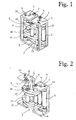
- the hinge according to Fig. 1 to Fig. 6 consists of a door frame-side receiving body 1, a door leaf-side receiving body 2 and a hinge bracket assembly 3 mounted in the receiving bodies 1 and 2 axes of rotation 4 and 5.
- the receiving body 1 and 2 are U-shaped profiles with a rear recess 6 and frontal openings 7 and 8.
- the recess 6 facilitates the assembly and assembly of the hinge.
- the openings 7 and 8 serve to receive fastening means for positioning and fixing the receiving body 1 and 2 in corresponding cavities of a door frame or a door leaf shown in phantom.
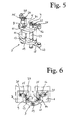
- the hinge bracket assembly 3 is composed of four paired superimposed hinge brackets 9, 10 and 11, 12, which have a substantially C-shaped profile, in which a corner region they are provided with a trough-like recess 13 and 14 respectively.
- the hinge bracket 9 and 11 or 10 and 12 can be rotated at the end remote from the recess 13 and 14 about the rotation axis 4 and 5 respectively.
- they are articulated to rocker arms 15, 16 and 17, 18 mounted pivotably in the receiving bodies 1, 2. They are also limited in pairs to a running through them central axis 19 of the hinge bracket assembly 3 limited relative to each other rotatable.
- the pivot axes 20, 21 and 22, 23 of the Wipparme 15, 16 and 17, 18 are arranged in the receiving bodies 1, 2 so that the Wipparme can pivot about 20 ° -25 °. Accordingly, the length of the Wipparme and the arrangement of their steering axles 24, 25 set.
- the axes of rotation 4 and 5 are also used as a stop means for limiting the relative rotational movement of the hinge bracket 9, 10 and 11, 12 by 12 during the pivoting of the door in the trough-like recesses 13, 14 of the hinge bracket 9, 10 and 11, can be latched ,
- the recesses 13, 14 are arranged relative to the axes of rotation 4 and 5 so that the hinge bracket 9, 10 and 11, 12 relative to each other by about 25 ° to 30 ° are rotatable.
- the axes of rotation 4 and 5 are cylindrical bolt or sleeve-like components. Their middle part 26, 27 serves as a vertical spacer between the hinge bracket pairs 9, 10 and 11, 12. The same applies to the middle part of the central axis 19 and for the steering axles 24 and 25th
- the pivot axes 20, 21; 22, 23 of the Wipparme 15, 16; 17, 18 are in turn cylindrically shaped dowel pins.
- the trough-like recesses 13, 14 have a circular contact surface which is adapted to the cylindrical peripheral surface of the axes of rotation 4 and 5. As in particular in Fig. 6 clearly visible, they thus form a low-friction hinge point for the hinge bracket 9 and 10 or 11 and 12.
- the hinge bracket assembly 3 is in accordance with the door closed in the starting position FIG. 3 and FIG. 4 in which the axes of rotation 4 and 5 are offset from the recesses 13, 14 of the hinge bracket.
- the hinge bracket assembly is in accordance with the door closed in the starting position FIG. 3 and FIG. 4 in which the axes of rotation 4 and 5 are offset from the recesses 13, 14 of the hinge bracket.
- you open the door these come successively with the axes of rotation 4 and 5 to the stop and thereby perform a combined movement resulting from a rotation about the axes of rotation 4 and 5 and a pivoting about the joints formed by the recesses 13, 14 joints composed.
- the hinge bracket assembly Upon reaching the maximum opening angle of 180 °, the hinge bracket assembly is in the end position according to Fig. 5 and Fig. 6 , By using typified components there arises a symmetrical arrangement to the center plane
- the inventive hinge contains only a few differently configured components, which are also predominantly produced from standardized products. Only the hinge bracket 9, 10; 11, 12 require a special design. But they are, as well as the Wipparme 20, 21; 22, 23, easy to produce as stamped sheet metal parts.
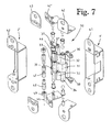
- Fig. 7 and Fig. 8 show a hinge 30, which consists of a tzargen solutionen receiving body 1 ', a door leaf-side receiving body 2' and a hinge bracket assembly 30 in the receiving bodies 1 ', 2' mounted rotary axes 33, 34.
- the receiving body 1, 2 are formed as pocket-shaped profiles.
- the hinge bracket assembly 30 consists of a middle and one each above and below this hinge bracket 31 and 32 composed, wherein the central hinge bracket 31 is mounted with one end about the axis of rotation 33 at a receiving body 2 ', but with the other end at the top and bottom of each in the other receiving body 1' pivotally mounted Wipparm 36, 38th hinged.
- the hinge brackets 32 located above and below this central hinge bow 31 are mounted in the opposite direction with one end at the common axis of rotation 34 of the receiving body 1 ', but with the other end at the top and bottom on each one in the other receiving body 2' pivotally mounted Wipparm 37, 39 hinged to an axle 37 '.
- This central axis 44 consists of several parts, which are designed such that the middle hinge bracket 31 and the two other hinge bracket 32 relative to each other in the Z direction are adjustable.
- bushes 47, axles 48 and screws 49 are arranged symmetrically one above the other. When adjusting the door in height, these screws 49 can be operated accordingly.
- Fig. 8 are for a horizontal adjustment of the door to the door frame in the X or Y direction the angle brackets 41, 42 of the receiving body 1 ', 2' associated with adjusting means.
- an adjusting means for an eccentric 45 at the angle brackets 42 of the door-side receiving body 2 'for adjusting the door in the X direction and the other in the door frame side receiving body 1' screw bushes 46 are provided for the adjustment in the Y direction.
- additional angle 41 ', 42' are present, which are on the one hand attached to the door frame and cause when turning this screw bushes 46 that the angle bracket 41 together with the receiving body 1 'are moved relative to the frame.
- the additional angle 42 'with the eccentrics 45 therein are connected to the hinge assembly and it is when rotating the eccentric 45 causes the fixed in the door receiving body 2' move together with the door in this X-direction.
- cover plates 43 can still be mounted on the eccentrics 45.
Abstract
Description
Die Erfindung betrifft ein verdecktes Scharnier für Türen und ähnliche Bauteile, mit einem türzargenseitigen Aufnahmekörper, einem türblattseitigen Aufnahmekörper und einer Scharnierbügelanordnung, die in den Aufnahmekörpern um in diesen gelagerten Drehachsen drehbar ist.The invention relates to a concealed hinge for doors and similar components, with a turzargenseitigen receiving body, a door leaf-side receiving body and a hinge bracket assembly which is rotatable in the receiving bodies to these mounted axes of rotation.
Ein Scharnier dieser Art ist in der Druckschrift
Der Erfindung liegt die Aufgabe zugrunde, diese Nachteile zu vermeiden und ein Scharnier der eingangs genannten Art zu schaffen, das auch verdeckt in Türzarge und Türblatt einbaubar ist und einen Öffnungswinkel um 180° ermöglicht, aber dessen Kinematik keine verschleissanfälligen Bauteile aufweist, funktionssicher arbeitet und fertigungs- und montagetechnisch einfach ist.The invention has for its object to avoid these disadvantages and to provide a hinge of the type mentioned, which is concealed in door frame and door leaf can be installed and an opening angle of 180 ° allows, but the kinematics has no wear-prone components, works reliably and manufacturing - and mounting technology is easy.
Diese Aufgabe wird erfindungsgemäss dadurch gelöst, dass die Scharnierbügelanordnung sich aus mindestens zwei übereinanderliegenden Scharnierbügeln zusammensetzt, deren ein Ende um die Drehachsen der Aufnahmekörper drehbar ist, während das andere Ende an in den Aufnahmekörpern schwenkbar gelagerten Wipparmen angelenkt ist, wobei die Scharnierbügel auch relativ zueinander um eine durch beide Scharnierbügel verlaufende Mittelachse begrenzt verdrehbar sind.This object is achieved according to the invention that the hinge bracket assembly is composed of at least two superimposed hinge brackets, one end of which is rotatable about the axes of rotation of the receiving body, while the other end is hinged to pivotally mounted in the receiving bodies Wipparmen, wherein the hinge bracket also relative to each other a running through both hinge bracket central axis are limited rotatable.
Das erfindungsgemässe Scharnier zeichnet sich dadurch aus, dass seine beweglichen Bestandteile nur Dreh- oder Schwenkbewegungen ausführen, ohne dass dafür verschleissanfällige Führungselemente nötig sind. Dies ist sowohl fertigungstechnisch als auch hinsichtlich der Funktionssicherheit des Scharniers vorteilhaft. Das Scharnier besteht zudem aus leicht typisierbaren Bauteilen, für deren Dimensionierung die Dreh- und Schwenkachsenanordnung des Scharniers massgeblich ist.The hinge according to the invention is characterized in that its movable components only perform rotary or pivotal movements without the need for wear-prone guide elements. This is advantageous both in terms of manufacturing technology and with regard to the functional safety of the hinge. The hinge is also made easily typeable components for whose dimensioning the rotary and pivot axis arrangement of the hinge is authoritative.
Es ist in diesem Sinne besonders zweckmässig, wenn die Scharnierbügel erfindungsgemäss ein im wesentlichen C-förmiges Profil aufweisen und in einem Eckbereich des Profils mit einer muldenartigen Aussparung versehen sind, in welche zur Begrenzung der relativen Drehbewegung der Scharnierbügel ein in den Aufnahmekörpern angeordnetes Anschlagmittel einrastbar ist.It is particularly expedient in this sense, when the hinge bracket according to the invention have a substantially C-shaped profile and are provided in a corner region of the profile with a trough-like recess, in which for limiting the relative rotational movement of the hinge bracket arranged in the receiving bodies stop means can be latched ,
Um sicherzustellen, dass die Scharnierbügel sich auch nach Erreichen der Raststellung leicht drehen können, sieht die Erfindung vor, dass die muldenartigen Aussparungen und die mit ihnen zusammenwirkenden Anschlagmittel mit kreisrunden Kontaktflächen versehen sind. Zur Erleichterung der Fertigung ist es zweckmässig, die Drehachsen der Scharnierbügel zylindrisch auszubilden und sie auch als kreisrunde Anschlagmittel für den jeweils anderen Scharnierbügel zu verwenden.To ensure that the hinge bracket can rotate easily even after reaching the locking position, the invention provides that the trough-like recesses and cooperating with them stop means are provided with circular contact surfaces. To facilitate the production, it is expedient to form the axes of rotation of the hinge bracket cylindrical and to use them as a circular stop means for each other hinge bracket.
Im Hinblick auf den maximalen Öffnungswinkel des Türblatts ist es für die Kinematik des Scharniers vorteilhaft, wenn die Scharnierbügel um ihre Mittelachse um ca. 25°-30° relativ zueinander verdrehbar sind. Es ist auch in diesem Zusammenhang zweckmässig, wenn die Kipparme um ca. 20°-25° schwenkbar sind.With regard to the maximum opening angle of the door leaf, it is advantageous for the kinematics of the hinge when the hinge brackets are rotatable about their central axis by about 25 ° -30 ° relative to each other. It is also expedient in this context if the tilting arms are pivotable about 20 ° -25 °.
Die Erfindung sieht ausserdem vor, dass bei grösser dimensionierten Scharnieren die Scharnierbügelanordnung sich aus zwei vertikal versetzten und gleich ausgebildeten Scharnierbügelpaaren mit gemeinsamen Drehachsen und einer gemeinsamen Mittelachse zusammensetzt. Durch die Verdoppelung der Grundanordnung ergibt sich eine stabile Konstruktion mit verhältnismässig geringem fertigungstechnischem Aufwand. Zweckmässigerweise ist die Scharnierbügelanordnung sowohl bei geschlossener Tür als auch bei um 180° geöffneter Tür symmetrisch, bezogen auf die Mittelebene der Anordnung.The invention also provides that for larger-dimensioned hinges, the hinge bracket assembly is composed of two vertically offset and identical Hinge pairs with common axes of rotation and a common center axis. By The doubling of the basic arrangement results in a stable construction with relatively low manufacturing expense. Conveniently, the hinge bracket assembly is symmetrical, both with the door closed and opened by 180 ° door, based on the center plane of the arrangement.
Die Aufnahmekörper des Scharniers sind vorzugsweise als U-förmige Blechprofile mit einer rückseitigen Aussparung zur Erleichterung des Zusammenbaus und der Montage sowie stirnseitigen Öffnungen zur Aufnahme von Befestigungs- oder Fixiermitteln hergestellt.The receiving body of the hinge are preferably made as U-shaped sheet metal profiles with a rear recess for ease of assembly and assembly and frontal openings for receiving fastening or fixing.
Die Erfindung wird nachfolgend anhand eines Ausführungsbeispiels unter Bezugnahme auf die Zeichnung näher erläutert. Es zeigen:
- Fig. 1
- ein erfindungsgemässes Scharnier im eingebauten Zustand, bei geschlossener Tür und perspektivisch dargestellt,
- Fig. 2
- das Scharnier nach
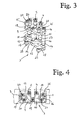
Fig. 1 , bei um 180° geöffneter Tür und perspektivisch dargestellt, - Fig. 3
- die Scharnierbügelanordnung des Scharniers nach
Fig. 1 , - Fig. 4
- die Scharnierbügelanordnung nach
Fig. 3 im Grundriss, - Fig. 5
- die Scharnierbügelanordnung des Scharniers aus
Fig. 2 , - Fig. 6
- die Scharnierbügelanordnung nach
Fig. 5 , im Grundriss gezeigt, - Fig. 7
- eine Variante eines erfindungsgemässen Scharniers in perspektivischer Explosionsdarstellung, und
- Fig. 8
- das Scharnier nach
Fig. 7 in perspektivischer Darstellung.
- Fig. 1
- an inventive hinge in the installed state, with the door closed and shown in perspective,
- Fig. 2
- the hinge after
Fig. 1 , when opened by 180 ° door and shown in perspective, - Fig. 3
- the hinge strap assembly of the hinge
Fig. 1 . - Fig. 4
- the hinge bracket assembly after
Fig. 3 in the floor plan, - Fig. 5
- the hinge bracket assembly of the hinge
Fig. 2 . - Fig. 6
- the hinge bracket assembly after
Fig. 5 , shown in plan, - Fig. 7
- a variant of a hinge according to the invention in an exploded perspective view, and
- Fig. 8
- the hinge after
Fig. 7 in perspective view.
Das Scharnier gemäss
Die Scharnierbügelanordnung 3 setzt sich aus vier paarweise übereinanderliegenden Scharnierbügeln 9, 10 und 11, 12 zusammen, die ein im wesentlichen C-förmiges Profil aufweisen, in dessen einem Eckbereich sie mit einer muldenartigen Aussparung 13 bzw. 14 versehen sind. Die Scharnierbügel 9 und 11 bzw. 10 und 12 können am von der Aussparung 13 bzw. 14 entfernten Ende um die Drehachse 4 bzw. 5 gedreht werden. An ihrem anderen Ende sind sie an in den Aufnahmekörpern 1, 2 schwenkbar gelagerten Wipparmen 15, 16 bzw. 17, 18 angelenkt. Sie sind zudem paarweise um eine durch sie verlaufende Mittelachse 19 der Scharnierbügelanordnung 3 begrenzt relativ zueinander verdrehbar.The
Die Schwenkachsen 20, 21 bzw. 22, 23 der Wipparme 15, 16 bzw. 17, 18 sind in den Aufnahmekörpern 1, 2 so angeordnet, dass die Wipparme um ca. 20°-25° schwenken können. Dementsprechend wird die Baulänge der Wipparme und die Anordnung ihrer Lenkachsen 24, 25 festgelegt.The
Die Drehachsen 4 und 5 dienen auch als Anschlagmittel zur Begrenzung der relativen Drehbewegung der Scharnierbügel 9, 10 bzw. 11, 12, indem sie beim Verschwenken der Tür in die muldenartigen Aussparungen 13, 14 der Scharnierbügel 9, 10 bzw. 11, 12 einrastbar sind. Die Aussparungen 13, 14 sind relativ zu den Drehachsen 4 und 5 so angeordnet, dass die Scharnierbügel 9, 10 bzw. 11, 12 relativ zueinander um ca. 25° bis 30° verdrehbar sind.The axes of
Die Drehachsen 4 und 5 sind zylindrische bolzen- oder hülsenartige Bauteile. Ihr Mittelteil 26, 27 dient als vertikaler Distanzhalter zwischen den Scharnierbügelpaaren 9, 10 und 11, 12. Entsprechendes gilt auch für den Mittelteil der Mittelachse 19 und für den der Lenkachsen 24 und 25.The axes of
Die Schwenkachsen 20, 21; 22, 23 der Wipparme 15, 16; 17, 18 sind ihrerseits zylindrisch ausgebildete Passstifte.The pivot axes 20, 21; 22, 23 of the
Die muldenartigen Aussparungen 13, 14 weisen eine kreisrunde Kontaktfläche auf, die der zylindrischen Umfangsfläche der Drehachsen 4 und 5 angepasst ist. Wie insbesondere in
Die Scharnierbügelanordnung 3 befindet sich bei geschlossener Tür in der Ausgangsstellung gemäss
Das erfindungsgemässe Scharnier enthält nur wenige unterschiedlich konfigurierte Bauteile, die zudem überwiegend aus standardisierten Produkten herstellbar sind. Lediglich die Scharnierbügel 9, 10; 11, 12 bedürfen einer besonderen Ausgestaltung. Sie sind aber, sowie die Wipparme 20, 21; 22, 23, leicht als gestanzte Blechteile herstellbar.The inventive hinge contains only a few differently configured components, which are also predominantly produced from standardized products. Only the
Es ist auch im Rahmen der Erfindung ohne weiteres möglich, die beiden Scharnierbügelpaare 9, 10 bzw. 11, 12 durch zwei ineinandergreifende einteilige Scharnierbügel zu ersetzen, die zweckmässigerweise einen Lagersteg und zwei Bügelarme aufweisen und etwa durch Strangformen oder Spritzgiessen herstellbar sind.It is also within the scope of the invention readily possible to replace the two hinge bracket pairs 9, 10 and 11, 12 by two intermeshing one-piece hinge bracket, which expediently have a bearing web and two bracket arms and can be produced by strand molding or injection molding.
Die Scharnierbügelanordnung 30 ist erfindungsgemäss aus einem mittleren und je einem ober- und unterhalb diesem liegenden Scharnierbügel 31 bzw. 32 zusammengesetzt, wobei der mittlere Scharnierbügel 31 mit dem einen Ende um die Drehachse 33 beim einen Aufnahmekörper 2' gelagert ist, indes mit dem andern Ende oben und unten an je einem in dem andern Aufnahmekörper 1' schwenkbar gelagerten Wipparm 36, 38 angelenkt. Hingegen sind die ober- und unterhalb diesem mittleren Scharnierbügel 31 befindlichen Scharnierbügel 32 umgekehrt mit dem einen Ende bei der gemeinsamen Drehachse 34 des Aufnahmekörpers 1' gelagert, indes mit dem andern Ende oben und unten an je einem in dem andern Aufnahmekörper 2' schwenkbar gelagerten Wipparm 37, 39 an einer Achse 37' angelenkt.The
Zudem sind alle drei Scharnierbügel 31, 32 um eine Mittelachse 44 verdrehbar gelagert und sie sind als Scharnierlappen mit Lagerbüchsen ausgebildet. Diese Mittelachse 44 besteht aus mehreren Teilen, welche derart ausgebildet sind, dass der mittlere Scharnierbügel 31 und die beiden andern Scharnierbügel 32 relativ zueinander in Z-Richtung verstellbar sind. Zweckmässigerweise sind hiefür Büchsen 47, Achsen 48 und Schrauben 49 symmetrisch übereinander angeordnet. Bei einem Justieren der Türe in der Höhe können diese Schrauben 49 entsprechend bedient werden.In addition, all three
Gemäss
Vorteilhaft sind Zusatzwinkel 41', 42' vorhanden, die einerseits am Türrahmen befestigt sind und beim Drehen dieser Schraubenbüchsen 46 bewirken, dass die Winkelträger 41 zusammen mit dem Aufnahmekörper 1' relativ zum Rahmen bewegt werden. Die Zusatzwinkel 42' mit den Exzentern 45 darin sind mit der Scharnieranordnung verbunden und es wird beim Verdrehen der Exzenter 45 bewirkt, dass die in der Türe fixierten Aufnahmekörper 2' zusammen mit der Türe sich in dieser X-Richtung bewegen. Ferner sind noch Abdeckbleche 43 bei den Exzentern 45 montierbar.Advantageously, additional angle 41 ', 42' are present, which are on the one hand attached to the door frame and cause when turning this
Claims (13)
dadurch gekennzeichnet, dass
die Scharnierbügelanordnung (3, 30) aus mindestens zwei übereinanderliegenden Scharnierbügeln (9, 10 bzw. 11, 12; 31, 32) zusammengesetzt ist, deren eines Ende jeweils um eine Drehachse (4, 5; 33, 34) beim jeweiligen Aufnahmekörper (1, 1'; 2, 2') drehbar ist, während das andere Ende an mindestens einem in dem jeweiligen Aufnahmekörper (1, 1'; 2, 2') schwenkbar gelagerten Wipparm (15, 16 bzw. 17, 18; 36, 38) angelenkt ist, wobei die Scharnierbügel (9, 10 bzw. 11, 12; 31, 32) relativ zueinander um eine durch beide Scharnierbügel verlaufende Mittelachse (19, 41) der Scharnierbügelanordnung (3, 30) verdrehbar sind.Concealed hinge for doors and similar components, comprising a retainer frame - side receiving body (1, 1 '), a door leaf - side receiving body (2, 2') and a hinge bracket assembly (3, 30) in the receiving bodies (1, 1 ', 2, 2 ') is rotatable in these mounted rotary axes (4, 5;),
characterized in that
the hinge strap arrangement (3, 30) is composed of at least two superimposed hinge straps (9, 10 or 11, 12, 31, 32), one end of which is in each case pivoted about an axis of rotation (4, 5, 33, 34) at the respective receiving body (1 , 1 ', 2, 2'), while the other end is rotatable on at least one rocker arm (15, 16 or 17, 18, 36, 38) pivotally mounted in the respective receiving body (1, 1 ', 2, 2') ), wherein the hinge straps (9, 10 or 11, 12, 31, 32) are rotatable relative to one another about a central axis (19, 41) of the hinge strap arrangement (3, 30) extending through both hinge straps.
die Scharnierbügel (9, 10 bzw. 11, 12) um die Mittelachse (19) um ca. 25° bis 30° relativ zueinander verdrehbar sind.Hinge according to one of the preceding claims 2 to 4, characterized in that
the hinge straps (9, 10 or 11, 12) about the central axis (19) by about 25 ° to 30 ° relative to each other are rotatable.
die Scharnierbügelanordnung (3) zwei vertikal versetzte und gleich ausgebildete Scharnierbügelpaare (9, 10 und 11, 12) mit gemeinsamen Drehachsen (4, 5) und einer gemeinsamen Mittelachse (19) umfasst.Hinge according to one of claims 1 to 6, characterized in that
the hinge bracket assembly (3) comprises two vertically offset and identically formed hinge bracket pairs (9, 10 and 11, 12) with common axes of rotation (4, 5) and a common central axis (19).
die Aufnahmekörper (1, 2) als U-förmige Blechprofile mit einer rückseitigen Aussparung (6) zur Erleichterung der Montage sowie stirnseitigen Öffnungen (7, 8) zur Aufnahme von Positionierungs- und Befestigungsmitteln hergestellt sind.Hinge according to one of claims 1 to 8, characterized in that
the receiving body (1, 2) as U-shaped sheet metal profiles with a rear recess (6) to facilitate mounting and frontal openings (7, 8) are made for receiving positioning and fastening means.
die Scharnierbügelanordnung (30) aus einem mittleren und je einem ober- und unterhalb diesem liegenden Scharnierbügel (31 bzw. 32) zusammengesetzt ist, wobei der mittlere Scharnierbügel (31) mit dem einen Ende um die Drehachse (33) beim einen Aufnahmekörper (2') gelagert ist, indes mit dem andern Ende an mindestens einem in dem andern Aufnahmekörper (1') schwenkbar gelagerten Wipparm (36, 38) angelenkt ist, dass hingegen die ober- und unterhalb diesem liegenden Scharnierbügel (32) umgekehrt mit dem einen Ende bei der Drehachse (34) des Aufnahmekörpers (1') gelagert sind, indes mit dem andern Ende an mindestens einem in dem andern Aufnahmekörper (2') schwenkbar gelagerten Wipparm (37, 39) angelenkt sind.Hinge according to one of claims 1 to 4, characterized in that
the hinge strap arrangement (30) is composed of a middle hinge clip and a respective upper hinge clip (31 or 32), the middle hinge clip (31) having one end about the axis of rotation (33) at a receiving body (2 '; ) is mounted, however, at the other end to at least one in the other receiving body (1 ') pivotally mounted Wipparm (36, 38) is hinged, however, that the above and below this hinge bracket (32) vice versa with the one end the axis of rotation (34) of the receiving body (1 ') are mounted, however, with the other end at least a in the other receiving body (2 ') pivotally mounted Wipparm (37, 39) are articulated.
Applications Claiming Priority (1)
| Application Number | Priority Date | Filing Date | Title |
|---|---|---|---|
| CH01109/11A CH705145B1 (en) | 2011-06-28 | 2011-06-28 | Covered hinge, particularly for doors. |
Publications (2)
| Publication Number | Publication Date |
|---|---|
| EP2540941A2 true EP2540941A2 (en) | 2013-01-02 |
| EP2540941A3 EP2540941A3 (en) | 2016-04-13 |
Family
ID=46514060
Family Applications (1)
| Application Number | Title | Priority Date | Filing Date |
|---|---|---|---|
| EP12004759.2A Withdrawn EP2540941A3 (en) | 2011-06-28 | 2012-06-26 | Concealed hinge for a door or similar components |
Country Status (2)
| Country | Link |
|---|---|
| EP (1) | EP2540941A3 (en) |
| CH (1) | CH705145B1 (en) |
Cited By (10)
| Publication number | Priority date | Publication date | Assignee | Title |
|---|---|---|---|---|
| ITUB20154592A1 (en) * | 2015-10-12 | 2017-04-12 | Kuantica S R L | Concealed invisible hinge for doors, structurally perfected. |
| WO2017065699A1 (en) * | 2015-10-12 | 2017-04-20 | Kuantica S.R.L. | Structurally improved invisible concealed hinge for doors |
| EP3168398A1 (en) | 2015-11-16 | 2017-05-17 | Christian Sitter | Hidden hinge for doors, windows or similar components |
| CN106761089A (en) * | 2017-03-12 | 2017-05-31 | 济南海能仪器股份有限公司 | For micromatic setting, the connection system and method including micromatic setting of door connection |
| IT201700114345A1 (en) * | 2017-10-12 | 2019-04-12 | Ivano Maddalena | HIDDEN ABSTRUSION HINGE WITH LOCKING DEVICE AT 45 ° - 180 ° |
| AT521484B1 (en) * | 2019-01-15 | 2020-02-15 | Peer Robert | hinge |
| US10655375B2 (en) * | 2018-01-18 | 2020-05-19 | Alpha Guardian | Security safe hinge |
| US10900265B2 (en) | 2015-10-12 | 2021-01-26 | Kuantica S.R.L. | Structurally improved invisible hidden door hinge with position adjustment |
| WO2022040958A1 (en) * | 2020-08-26 | 2022-03-03 | 肇庆市高要区兆高金属科技有限公司 | Adjustable hinge |
| WO2022040960A1 (en) * | 2020-08-26 | 2022-03-03 | 肇庆市高要区兆高金属科技有限公司 | Hidden hinge |
Citations (1)
| Publication number | Priority date | Publication date | Assignee | Title |
|---|---|---|---|---|
| CH698960A2 (en) | 2008-06-06 | 2009-12-15 | Simonswerk Gmbh | Door hinge for a concealed arrangement between door frame and door leaf rebated. |
Family Cites Families (5)
| Publication number | Priority date | Publication date | Assignee | Title |
|---|---|---|---|---|
| FR772468A (en) * | 1933-05-23 | 1934-10-30 | Virtual axis of rotation hinge | |
| DE810966C (en) * | 1950-01-17 | 1951-08-16 | Emil Lupp Fa | Invisible hinge for all types of flaps |
| DE1168795B (en) * | 1960-05-16 | 1964-04-23 | Charles J Soss | Concealed hinge |
| BE1018621A5 (en) * | 2008-12-23 | 2011-05-03 | Argent Alu Nv | HINGE. |
| ITRN20090009U1 (en) * | 2009-07-30 | 2011-01-31 | Koblenz Spa | TOTAL HIDDEN HINGE WITH ADJUSTMENT ON THREE AXIS FOR DOORS AND / OR FURNITURE DOORS. |
-
2011
- 2011-06-28 CH CH01109/11A patent/CH705145B1/en unknown
-
2012
- 2012-06-26 EP EP12004759.2A patent/EP2540941A3/en not_active Withdrawn
Patent Citations (1)
| Publication number | Priority date | Publication date | Assignee | Title |
|---|---|---|---|---|
| CH698960A2 (en) | 2008-06-06 | 2009-12-15 | Simonswerk Gmbh | Door hinge for a concealed arrangement between door frame and door leaf rebated. |
Cited By (15)
| Publication number | Priority date | Publication date | Assignee | Title |
|---|---|---|---|---|
| CN108431354B (en) * | 2015-10-12 | 2019-12-10 | 关迪卡有限责任公司 | Structurally improved concealed hinge for doors |
| WO2017065699A1 (en) * | 2015-10-12 | 2017-04-20 | Kuantica S.R.L. | Structurally improved invisible concealed hinge for doors |
| ITUB20154592A1 (en) * | 2015-10-12 | 2017-04-12 | Kuantica S R L | Concealed invisible hinge for doors, structurally perfected. |
| CN108431354A (en) * | 2015-10-12 | 2018-08-21 | 关迪卡有限责任公司 | The improved built-in hidden hinge for door in structure |
| US10900265B2 (en) | 2015-10-12 | 2021-01-26 | Kuantica S.R.L. | Structurally improved invisible hidden door hinge with position adjustment |
| EP3362623B1 (en) | 2015-10-12 | 2019-04-24 | Kuantica S.r.l. | Invisible concealed hinge for doors |
| RU2707594C2 (en) * | 2015-10-12 | 2019-11-28 | Куантика С.Р.Л. | Structurally improved invisible concealed hinge for doors |
| EP3168398A1 (en) | 2015-11-16 | 2017-05-17 | Christian Sitter | Hidden hinge for doors, windows or similar components |
| CN106761089A (en) * | 2017-03-12 | 2017-05-31 | 济南海能仪器股份有限公司 | For micromatic setting, the connection system and method including micromatic setting of door connection |
| IT201700114345A1 (en) * | 2017-10-12 | 2019-04-12 | Ivano Maddalena | HIDDEN ABSTRUSION HINGE WITH LOCKING DEVICE AT 45 ° - 180 ° |
| US10655375B2 (en) * | 2018-01-18 | 2020-05-19 | Alpha Guardian | Security safe hinge |
| AT521484B1 (en) * | 2019-01-15 | 2020-02-15 | Peer Robert | hinge |
| AT521484A4 (en) * | 2019-01-15 | 2020-02-15 | Peer Robert | hinge |
| WO2022040958A1 (en) * | 2020-08-26 | 2022-03-03 | 肇庆市高要区兆高金属科技有限公司 | Adjustable hinge |
| WO2022040960A1 (en) * | 2020-08-26 | 2022-03-03 | 肇庆市高要区兆高金属科技有限公司 | Hidden hinge |
Also Published As
| Publication number | Publication date |
|---|---|
| EP2540941A3 (en) | 2016-04-13 |
| CH705145A2 (en) | 2012-12-31 |
| CH705145B1 (en) | 2015-08-28 |
Similar Documents
| Publication | Publication Date | Title |
|---|---|---|
| EP2540941A2 (en) | Concealed hinge for a door or similar components | |
| EP2130997B1 (en) | Door with a hinge | |
| EP3168398B1 (en) | Hidden hinge for doors, windows or similar components | |
| DE102008028633B4 (en) | Drive arrangement for a swing wing | |
| EP2754813B1 (en) | Hinge, in particular for plastic doors and windows | |
| EP2721236A1 (en) | Internal 180-degree hinge for an arrangement of cabinets in a row | |
| EP3175068A1 (en) | Fitting arrangement | |
| DE3343366C2 (en) | ||
| WO2010028715A1 (en) | Folding door | |
| DE202018107202U1 (en) | End fitting for a push chain | |
| DE102004007823A1 (en) | Hidden 180 degree hinge assembly for two swinging doors for cupboards has baseplate with flanges holding two double rack-and- pinion assemblies with swing links | |
| EP1555368B1 (en) | Fitting for a turn and a tilting motion of a wing of a building window or a building door as well as parallel sliding tilting window or door with such a fitting | |
| DE102008028598B4 (en) | Screen door | |
| DE10023761B4 (en) | Lying door drive | |
| DE3939127C2 (en) | ||
| DE8103368U1 (en) | Tilt and turn window or door | |
| DE4333724A1 (en) | Casement or the like | |
| DE102017100495A1 (en) | Tilting fitting for a window sash | |
| EP2369111B1 (en) | Corner bearing for concealed assembly | |
| DE4031665A1 (en) | Folding door for room or article of furniture - has individual leaves connected one to another by flexible hinges | |
| DE19854739C1 (en) | Support roller assembly for building movable door or window leaf has adjusting screw engaging semi-circular notch in cantilever | |
| DE2727585C2 (en) | Adjustable handlebar pivot bearing for bottom-hung windows or doors | |
| DE3129606A1 (en) | Double-jointed hinge for large opening angles of doors or the like | |
| DE7709672U1 (en) | ADJUSTABLE LOWER CORNER BEARING FOR TILT-TURN LEAF | |
| DE102014221290B3 (en) | Connecting arrangement for a window, a door or the like |
Legal Events
| Date | Code | Title | Description |
|---|---|---|---|
| PUAI | Public reference made under article 153(3) epc to a published international application that has entered the european phase |
Free format text: ORIGINAL CODE: 0009012 |
|
| AK | Designated contracting states |
Kind code of ref document: A2 Designated state(s): AL AT BE BG CH CY CZ DE DK EE ES FI FR GB GR HR HU IE IS IT LI LT LU LV MC MK MT NL NO PL PT RO RS SE SI SK SM TR |
|
| AX | Request for extension of the european patent |
Extension state: BA ME |
|
| PUAL | Search report despatched |
Free format text: ORIGINAL CODE: 0009013 |
|
| AK | Designated contracting states |
Kind code of ref document: A3 Designated state(s): AL AT BE BG CH CY CZ DE DK EE ES FI FR GB GR HR HU IE IS IT LI LT LU LV MC MK MT NL NO PL PT RO RS SE SI SK SM TR |
|
| AX | Request for extension of the european patent |
Extension state: BA ME |
|
| RIC1 | Information provided on ipc code assigned before grant |
Ipc: E05D 7/00 20060101ALN20160304BHEP Ipc: E05D 7/04 20060101ALN20160304BHEP Ipc: E05D 3/16 20060101AFI20160304BHEP |
|
| STAA | Information on the status of an ep patent application or granted ep patent |
Free format text: STATUS: THE APPLICATION IS DEEMED TO BE WITHDRAWN |
|
| 18D | Application deemed to be withdrawn |
Effective date: 20161014 |