EP2540915A1 - Electrical construction machine - Google Patents
Electrical construction machine Download PDFInfo
- Publication number
- EP2540915A1 EP2540915A1 EP10846173A EP10846173A EP2540915A1 EP 2540915 A1 EP2540915 A1 EP 2540915A1 EP 10846173 A EP10846173 A EP 10846173A EP 10846173 A EP10846173 A EP 10846173A EP 2540915 A1 EP2540915 A1 EP 2540915A1
- Authority
- EP
- European Patent Office
- Prior art keywords
- inverter
- electric motor
- oil tank
- machine room
- battery
- Prior art date
- Legal status (The legal status is an assumption and is not a legal conclusion. Google has not performed a legal analysis and makes no representation as to the accuracy of the status listed.)
- Granted
Links
- 238000010276 construction Methods 0.000 title claims description 23
- 238000001816 cooling Methods 0.000 claims abstract description 165
- 238000005192 partition Methods 0.000 claims abstract description 63
- 239000003921 oil Substances 0.000 claims description 101
- 239000000498 cooling water Substances 0.000 claims description 39
- 239000010720 hydraulic oil Substances 0.000 claims description 19
- XLYOFNOQVPJJNP-UHFFFAOYSA-N water Substances O XLYOFNOQVPJJNP-UHFFFAOYSA-N 0.000 claims description 12
- 230000000694 effects Effects 0.000 claims description 3
- 239000012530 fluid Substances 0.000 claims description 2
- 238000000638 solvent extraction Methods 0.000 claims description 2
- 229910000831 Steel Inorganic materials 0.000 description 3
- 239000004576 sand Substances 0.000 description 3
- 239000010959 steel Substances 0.000 description 3
- HBBGRARXTFLTSG-UHFFFAOYSA-N Lithium ion Chemical compound [Li+] HBBGRARXTFLTSG-UHFFFAOYSA-N 0.000 description 1
- 238000002485 combustion reaction Methods 0.000 description 1
- 230000007423 decrease Effects 0.000 description 1
- 230000002542 deteriorative effect Effects 0.000 description 1
- 238000010586 diagram Methods 0.000 description 1
- 230000005611 electricity Effects 0.000 description 1
- 229910001416 lithium ion Inorganic materials 0.000 description 1
- 238000009423 ventilation Methods 0.000 description 1
Images


Classifications
-
- E—FIXED CONSTRUCTIONS
- E02—HYDRAULIC ENGINEERING; FOUNDATIONS; SOIL SHIFTING
- E02F—DREDGING; SOIL-SHIFTING
- E02F9/00—Component parts of dredgers or soil-shifting machines, not restricted to one of the kinds covered by groups E02F3/00 - E02F7/00
- E02F9/20—Drives; Control devices
- E02F9/22—Hydraulic or pneumatic drives
-
- B—PERFORMING OPERATIONS; TRANSPORTING
- B60—VEHICLES IN GENERAL
- B60K—ARRANGEMENT OR MOUNTING OF PROPULSION UNITS OR OF TRANSMISSIONS IN VEHICLES; ARRANGEMENT OR MOUNTING OF PLURAL DIVERSE PRIME-MOVERS IN VEHICLES; AUXILIARY DRIVES FOR VEHICLES; INSTRUMENTATION OR DASHBOARDS FOR VEHICLES; ARRANGEMENTS IN CONNECTION WITH COOLING, AIR INTAKE, GAS EXHAUST OR FUEL SUPPLY OF PROPULSION UNITS IN VEHICLES
- B60K11/00—Arrangement in connection with cooling of propulsion units
- B60K11/08—Air inlets for cooling; Shutters or blinds therefor
-
- E—FIXED CONSTRUCTIONS
- E02—HYDRAULIC ENGINEERING; FOUNDATIONS; SOIL SHIFTING
- E02F—DREDGING; SOIL-SHIFTING
- E02F9/00—Component parts of dredgers or soil-shifting machines, not restricted to one of the kinds covered by groups E02F3/00 - E02F7/00
- E02F9/08—Superstructures; Supports for superstructures
- E02F9/0808—Improving mounting or assembling, e.g. frame elements, disposition of all the components on the superstructures
-
- E—FIXED CONSTRUCTIONS
- E02—HYDRAULIC ENGINEERING; FOUNDATIONS; SOIL SHIFTING
- E02F—DREDGING; SOIL-SHIFTING
- E02F9/00—Component parts of dredgers or soil-shifting machines, not restricted to one of the kinds covered by groups E02F3/00 - E02F7/00
- E02F9/08—Superstructures; Supports for superstructures
- E02F9/0858—Arrangement of component parts installed on superstructures not otherwise provided for, e.g. electric components, fenders, air-conditioning units
- E02F9/0866—Engine compartment, e.g. heat exchangers, exhaust filters, cooling devices, silencers, mufflers, position of hydraulic pumps in the engine compartment
-
- E—FIXED CONSTRUCTIONS
- E02—HYDRAULIC ENGINEERING; FOUNDATIONS; SOIL SHIFTING
- E02F—DREDGING; SOIL-SHIFTING
- E02F9/00—Component parts of dredgers or soil-shifting machines, not restricted to one of the kinds covered by groups E02F3/00 - E02F7/00
- E02F9/08—Superstructures; Supports for superstructures
- E02F9/0858—Arrangement of component parts installed on superstructures not otherwise provided for, e.g. electric components, fenders, air-conditioning units
- E02F9/0883—Tanks, e.g. oil tank, urea tank, fuel tank
-
- E—FIXED CONSTRUCTIONS
- E02—HYDRAULIC ENGINEERING; FOUNDATIONS; SOIL SHIFTING
- E02F—DREDGING; SOIL-SHIFTING
- E02F9/00—Component parts of dredgers or soil-shifting machines, not restricted to one of the kinds covered by groups E02F3/00 - E02F7/00
- E02F9/20—Drives; Control devices
- E02F9/22—Hydraulic or pneumatic drives
- E02F9/226—Safety arrangements, e.g. hydraulic driven fans, preventing cavitation, leakage, overheating
-
- B—PERFORMING OPERATIONS; TRANSPORTING
- B60—VEHICLES IN GENERAL
- B60Y—INDEXING SCHEME RELATING TO ASPECTS CROSS-CUTTING VEHICLE TECHNOLOGY
- B60Y2200/00—Type of vehicle
- B60Y2200/40—Special vehicles
- B60Y2200/41—Construction vehicles, e.g. graders, excavators
- B60Y2200/412—Excavators
Definitions
- the present invention relates to an electrical construction machine such as a hydraulic excavator, a wheel loader, or the like equipped with an electric motor as its power source.
- a construction machine such as a hydraulic excavator which is used in excavating operations and demolition operations employs an engine (internal combustion engine) as a power source, and a hydraulic pump is driven by this engine.
- the arrangement provided is such that pressure oil (working oil) is supplied from the hydraulic pump to various hydraulic actuators including a hydraulic motor for traveling, a hydraulic motor for revolving, a hydraulic cylinder for constituting a working mechanism, and the like.
- an electrical hydraulic excavator which has an electric motor as a power source for driving the hydraulic pump instead of the engine and a battery for supplying electricity to this electric motor.
- the electrical hydraulic excavator according to this conventional art is constructed such that an operator's seat is arranged on the left side in the left-right direction of an upper revolving structure, the hydraulic pump, the electric motor, an oil tank, a heat exchanger (oil cooler), and the like are arranged on the right side of the operator's seat, and the battery is arranged on the rear side of the operator's seat.
- the hydraulic pump, the electric motor, the oil tank, the heat exchanger, the battery, and the like are accommodated in an identical accommodating space (namely, a single accommodating space) covered by a cover, and the hydraulic pump, the electric motor, the oil tank, the heat exchanger, and the like are arranged to be cooled by cooling air which is circulated in the accommodating space by a cooling fan (e.g., Japanese Patent Laid-Open No. Hei 11-149906 A ).
- a cooling fan e.g., Japanese Patent Laid-Open No. Hei 11-149906 A
- the performance of a lithium ion battery which is suitably used for mounting in a vehicle normally declines when the ambient temperature reaches 50°C or higher.
- the above-described electrical hydraulic excavator according to the conventional art is so arranged that the hydraulic pump, the electric motor, the oil tank, the heat exchanger, the battery, and the like are accommodated in the single accommodating space covered by the cover.
- an object of the present invention to provide an electrical construction machine which is capable of protecting the battery from the heat generated from the installed equipment such as the hydraulic pump, the electric motor, and the like arranged in a machine room and is capable of efficiently cooling the installed equipment arranged in the machine room.
- the present invention is applied to an electrical construction machine including a vehicle body frame which constitutes a support structure of a vehicle body and which has a working mechanism mounted on a front side in a front-rear direction; an operator's seat provided on the vehicle body frame on a left side in a left-right direction; a hydraulic pump provided on a right side of the operator's seat to supply hydraulic oil to the working mechanism; an electric motor for driving the hydraulic pump; an inverter for controlling a drive voltage of the electric motor; an oil tank for storing the hydraulic oil which is supplied to the working mechanism; a heat exchanger for cooling a heated fluid; a battery provided on a rear side of the operator's seat to effect the feeding of electric power to the electric motor; and an exterior cover provided in such a manner as to cover the hydraulic pump, the electric motor, the inverter, the oil tank, the heat exchanger, and the battery.
- a characteristic feature of the construction adopted in the present invention lies in that the vehicle body frame is provided with a partition plate for partitioning an interior of the exterior cover into a machine room for accommodating the hydraulic pump, the electric motor, the inverter, the oil tank, and the heat exchanger and into a battery room for accommodating the battery, and a cooling fan for circulating cooling air inside the machine room is provided in the machine room.
- the interior of the exterior cover can be partitioned into the battery room for accommodating the battery and into the machine room for accommodating the hydraulic pump, the electric motor, the inverter, the oil tank, and the heat exchanger.
- heat generated from the mounted equipment such as the hydraulic pump and the electric motor can be restrained by the partition plate from being transmitted to the battery, thereby making it possible to maintain the surroundings of the battery at an appropriate temperature.
- the feeding of electric power from the battery to the electric motor can be effected stably over a long period of time, making it possible to enhance the reliability of the construction machine.
- the mounted equipment such as the hydraulic pump and the electric motor can be reliably cooled by the cooling air.
- the oil tank is arranged on a front side of the machine room
- the electric motor and the hydraulic pump are arranged on a rear side of the machine room
- the inverter is arranged upwardly of the electric motor and the hydraulic pump
- the cooling fan and the heat exchanger are arranged forwardly of the electric motor, the hydraulic pump, and the inverter and rearwardly of the oil tank.
- the cooling air which is circulated in the machine room by the cooling fan can be divided into a first cooling air route for cooling the oil tank and a second cooling air route for cooling the electric motor, the hydraulic pump, and the inverter.
- the oil tank can be efficiently cooled by the cooling air flowing along the first cooling air route, and the electric motor, the hydraulic pump, and the inverter can be efficiently cooled by the cooling air flowing along the second cooling air route.
- the cooling fan is constituted by a blow-out type cooling fan which blows air in the machine room to an outside
- the exterior cover is provided with an oil tank cooling air inlet port provided at a position opposing to the oil tank to suck outside air to the oil tank, an inverter cooling air inlet port provided at a position opposing to the inverter to suck the outside air to the inverter, and an exhaust port provided at a position opposing to the cooling fan to exhaust the air in the machine room by the cooling fan.
- the oil tank can be efficiently cooled by the outside air introduced into the machine room from the oil tank cooling air inlet port, and the electric motor, the hydraulic pump, and the inverter can be efficiently cooled by the outside air introduced into the machine room from the inverter cooling air inlet port. Furthermore, the heat exchanger can be efficiently cooled by the large quantity of outside air introduced into the machine room from the oil tank cooling air inlet port and the inverter cooling air inlet port.
- a communicating hole for allowing the machine room and the battery room to communicate with each other is provided in the partition plate.
- the air inside the battery room can be allowed to flow into the machine room through the communicating hole, and can be exhausted to the outside through the exhaust port of the exterior cover, thereby making it possible to restrain the interior of the battery room from assuming a high temperature owing to the heat generated by the battery.
- an auxiliary fan for leading the air inside the battery room into the machine room through the communicating hole is provided in the partition plate.
- a flat plate-shaped motor-pump support plate for supporting the electric motor and the hydraulic pump is provided on the vehicle body frame, and a motor-pump cooling air inlet port for sucking the outside air toward the electric motor and the hydraulic pump is provided in the motor-pump support plate.
- the electric motor and the hydraulic pump are placed on the motor-pump support plate.
- the blow-out type cooling fan is operated, outside air is sucked into the machine room through the motor-pump cooling air inlet port of the motor-pump support plate, and this outside air can be directly supplied to the electric motor and the hydraulic pump along the second cooling air route, so that the electric motor and the hydraulic pump can be cooled more efficiently by this outside air.
- the electric motor is covered by a motor case having a water jacket
- the inverter is covered by an inverter case accommodating an inverter circuit and having a water jacket, cooling water being arranged to be circulated through the water jackets of the motor case and the inverter case.
- the electric motor is cooled by the cooling air flowing in the machine room and by the cooling water flowing through the water jacket of the motor case.
- the inverter is cooled by the cooling air flowing in the machine room and by the cooling water flowing through the water jacket of the inverter case. Accordingly, it is possible to further enhance the efficiency of cooling the electric motor and the inverter.
- the heat exchanger is constituted by an oil cooler and a radiator, the oil cooler being adapted to cool the hydraulic oil which is recirculated into the oil tank, the radiator being adapted to cool the cooling water flowing through the water jackets of the motor case and the inverter case.
- the vehicle body is constituted by an automotive lower traveling structure and an upper revolving structure which is swingably mounted on the lower traveling structure, and the vehicle body frame constitutes a support structure of the upper revolving structure.
- the interior of the exterior cover can be partitioned into the battery room for accommodating the battery and into the machine room for accommodating the hydraulic pump, the electric motor, the inverter, the oil tank, and the heat exchanger by the partition plate provided on the vehicle body frame of the upper revolving structure.
- the electrical construction machine in accordance with the present invention is applicable to an electrical hydraulic excavator, an electrical hydraulic crane, or the like which has a lower traveling structure and an upper revolving structure.
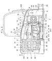
- an electrical hydraulic excavator designated at 1 is an electrical hydraulic excavator, and this hydraulic excavator 1 is constituted by a crawler type automotive lower traveling structure 2 and an upper revolving structure 3 which is swingably mounted on the lower traveling structure 2 and constitutes a vehicle body together with the lower traveling structure 2.
- a swing type working mechanism 4 for performing such as the operation of excavating earth and sand is provided on a front side of the upper revolving structure 3.
- the working mechanism 4 is constituted by a boom 4A, an arm 4B, a bucket 4C, a boom cylinder 4D, an arm cylinder 4E, a bucket cylinder 4F, and the like.
- the hydraulic excavator 1 has a hydraulic pump 17, an electric motor 18, and the like which will be described below and serve as a driving source.
- the hydraulic excavator 1 supplies hydraulic pressure oil from the hydraulic pump 17 toward such hydraulic equipment as a hydraulic motor for traveling, a hydraulic motor for revolving (neither is shown), and the respective cylinders 4D, 4E, and 4F for constituting the working mechanism 4 by driving the hydraulic pump 17 by the electric motor 18.
- the upper revolving structure 3 effects a revolving operation on the lower traveling structure 2 with a revolving center P as a center and is constituted by a revolving frame 5, a partition plate 7, an operator's seat 15, a canopy 16, the hydraulic pump 17, the electric motor 18, an inverter 19, an oil tank 20, a heat exchanger 21, a cooling fan 30, a battery 31, an exterior cover 34, and the like which will be described hereinafter.
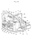
- Designated at 5 is the revolving frame serving as a vehicle body frame which is a base of the upper revolving structure 3, and the revolving frame 5 is formed as a rigid supporting structure, as shown in Fig. 5 .
- the revolving frame 5 includes a bottom plate 5A in the form of a thick flat plate provided in its central portion as viewed in the left-right direction in such a manner as to extend in the front-rear direction; a left vertical plate 5B and a right vertical plate 5C erected on an upper surface side of the bottom plate 5A at an interval therebetween and extending in the front-rear direction; a support bracket 5D provided at front end portions of these vertical plates 5B and 5C; a lateral plate 5E erected on the bottom plate 5A in such a manner as to traverse the left and right vertical plates 5B and 5C at an intermediate portion in the front-rear direction; a left extension beam 5F extending laterally leftward from a rear end side of the left vertical plate 5B; and two right extension beams 5G extending laterally rightward from the right vertical plate 5C at an interval therebetween in the front-rear direction.
- a bottom plate 5A in the form of a thick flat plate provided in its central portion as viewed in
- the revolving frame 5 includes an L-shaped left frame member 5H which is connected to the left vertical plate 5B in the vicinity of the support bracket 5D and is connected to left end portions of the lateral plate 5E and the left extension beam 5F; a right frame member 5I which is disposed on the right side of the bottom plate 5A and which is connected to right end portions of the right extension beams 5G and is connected to a front side of the bottom plate 5A; a front connecting member 5J in the form of a thick flat plate for connecting front sides of the right vertical plate 5C and the right frame member 5I; and a heat exchanger support plate 5K which is formed of a plate bent in the form of an inverse L-shape in a side view and is fixed to an upper end of the front side right extension beam 5G and to the front connecting member 5J in such a manner as to bridge them.
- the arrangement provided is such that the working mechanism 4 is mounted swingably in the left-right direction on the support bracket 5D located on the front end side of the revolving frame 5, and the below-described battery 31 is mounted on the rear end side of the revolving frame 5.
- the support member 6 is a support member erected on an intermediate portion in the front-rear direction of the revolving frame 5, and the support member 6 supports the partition plate 7, the canopy 16, the hydraulic pump 17, the electric motor 18, the inverter 19, and the like which will be described hereinafter.
- the support member 6 is largely constituted by a lateral beam 6A extending in the left-right direction above the bottom plate 5A; a rod-like left vertical beam 6B extending downwardly from a left end portion of the lateral beam 6A; a right vertical beam 6C constituted by an inverse U-shaped frame body and extending downwardly from a right end portion of the lateral beam 6A; a below-described plate body 6D; and support plate mounting brackets 6E and 6F.
- a front end portion of the right vertical beam 6C is fixed to a right end portion of the lateral plate 5E of the revolving frame 5, and a rear end portion of the right vertical beam 6C is fixed to the right vertical plate 5C of the revolving frame 5.
- the support member 6 has the plate body 6D having a trapezoidal shape and located in a range from an upper end portion of the right vertical beam 6C to an intermediate portion thereof in the vertical direction.
- the plate body 6D is fixed to the right vertical beam 6C and constitutes a part of a below-described vertical partition plate 8.
- a communicating hole 39 and an auxiliary fan 40 are arranged to be provided in this plate body 6D.
- the support member 6 has the two support plate mounting brackets 6E and 6F which extend in the left-right direction while being bent in an L-shape and are spaced apart from each other in the front-rear direction.
- front and rear support plate mounting brackets 6E and 6F are fixed to a lower end side of the plate body 6D on the right vertical beam 6C, and right lower end portions thereof are respectively fixed to the front and rear right extension beams 6G for making up the revolving frame 5.
- the partition plate 7 partitions the interior of the below-described exterior cover 34 into a machine room 10 and a battery room 11, as shown in Figs. 3 , 4 , and 6 .
- the partition plate 7 is constituted by the vertical partition plate 8 which is erected on the left vertical plate 5B of the revolving frame 5 and extends in the front-rear direction along the left vertical plate 5B and by a lateral partition plate 9 which extends in the left-right direction between a rear end portion of the vertical partition plate 8 and a rear end portion of the right frame member 5I of the revolving frame 5.
- the vertical partition plate 8 is constituted by an upper vertical partition plate 8A extending in the front-rear direction in a range from a front end side of the right vertical plate 5C for constituting the revolving frame 5 to a rear end portion of the right vertical beam 6C for constituting the support member 6 and by a substantially rectangular lower vertical partition plate 8B arranged on a lower side of a rear portion of the upper vertical partition plate 8A.
- a trapezoidal notched portion 8A1 corresponding to the right vertical beam 6C of the support member 6 is formed at a rear end side of the upper vertical partition plate 8A.
- the arrangement provided is such that in a state in which the upper vertical partition plate 8A is disposed on the right vertical plate 5C of the revolving frame 5, the notched portion 8A1 is engaged with an outer periphery of the right vertical beam 6C of the support member 6 without a clearance.
- the plate body 6D since the plate body 6D is fixed in the range from the upper end portion of the right vertical beam 6C to the intermediate portion thereof in the vertical direction, the plate body 6D is disposed in a substantially identical plane to that of the upper vertical partition plate 8A in the state in which the notched portion 8A1 of the upper vertical partition plate 8A is engaged with the right vertical beam 6C.
- the lower vertical partition plate 8B As the lower vertical partition plate 8B is disposed on the lower side of the rear portion of the upper vertical partition plate 8A, the upper vertical partition plate 8A, the plate body 6D of the right vertical beam 6C, and the lower vertical partition plate 8B are arranged to form an identical plate extending in the front-rear direction.
- the plate body 6D which is provided on the right vertical beam 6C of the support member 6 constitutes a part of the vertical partition plate 8.
- the lateral partition plate 9 is formed by a rectangular flat plate which extends vertically and in parallel in the left-right direction with the support plate mounting bracket 6F of the support member 6.
- this lateral partition plate 9 its one end side is mounted on a rear end portion of the right vertical beam 6C for constituting the support member 6 and juts out laterally rightward from the rear end portion of the vertical partition plate 8, and its other end side extends to a rear end portion of the right frame member 5I for constituting the revolving frame 5.
- the partition plate 7 is arranged in an L-shape as viewed from above by means of the vertical partition plate 8 and the lateral partition plate 9. Namely, as shown in Fig. 4 , the partition plate 7 is arranged to partition the interior of the exterior cover 34 into the machine room 10, which is located on the right side of the below-described operator's seat 15 and accommodates the hydraulic pump 17, the electric motor 18, the inverter 19, the oil tank 20, the heat exchanger 21, the cooling fan 30, and the like, which will be described hereinafter, and into the battery room 11, which is located on the rear side of the operator's seat 15 and accommodates the below-described battery 31.
- a motor-pump support plate provided in the form of a flat plate and located between the two right extension beams 5G located on the front and rear sides of the revolving frame 5.
- the motor-pump support plate 12 supports the hydraulic pump 17 and the electric motor 18.
- the motor-pump support plate 12 is formed of a rectangular flat plate by using a steel plate or the like, and both its ends in the front-rear direction are respectively fixed to the right extension beams 5G.
- a below-described motor-pump cooling air inlet port 37 is formed in a central portion of the motor-pump support plate 12.
- Indicated at 13 is an inverter support plate provided on upper end sides of the front and rear support plate mounting brackets 6E and 6F of the support member 6 and located above the motor-pump support plate 12.
- the inverter support plate 13 supports the below-described inverter 19.
- the inverter support plate 13 is formed as a rectangular flat plate by using a steel plate or the like, and both its ends in the front-rear direction are respectively fixed to the front and rear support plate mounting brackets 6E and 6F.
- this lower plate 14 is formed as a substantially trapezoidal flat plate by using a steel plate or the like, and is fixed between the right vertical plate 5C and the front side right extension beam 5G in a state in which an identical plane is formed with the motor-pump support plate 12 and the heat exchanger support plate 5K of the revolving frame 5. Further, the lower plate 14 restrains the cooling air introduced into the machine room 10 by the below-described cooling fan 30 from flowing around to the lower side of the below-described heat exchanger 21 disposed on the heat exchanger support plate 5K.
- Indicated at 15 is the operator's seat provided on the revolving frame 5, and the operator's seat 15 is arranged leftwardly of the revolving center P of the upper revolving structure 3 (see Fig. 4 ).
- This operator's seat 15 is for an operator who operates the hydraulic excavator 1 to be seated thereon, and the operator's seat 15 is covered from above by the 4-post type canopy 16 which is supported by the support member 6.
- Indicated at 17 is the hydraulic pump provided on a rear side of the machine room 10 by being located on the right side of the operator's seat 15. As shown in Figs. 3 and 12 , the hydraulic pump 17 is mounted on the motor-pump support plate 12 together with the below-described electric motor 18. As the hydraulic pump 17 is driven by the electric motor 18, the hydraulic pump 17 discharges hydraulic pressure oil (hydraulic oil) toward various items of hydraulic equipment mounted on the hydraulic excavator 1.
- hydraulic pressure oil hydraulic pressure oil
- the electric motor 18 mounted on the motor-pump support plate 12 with the hydraulic pump 17. As electric power is fed from the below-described battery 31 to the electric motor 18, the electric motor 18 drives the hydraulic pump 17. As shown in Figs. 13 and 15 , the electric motor 18 is constituted by a motor body 18A and a motor case 18B covering the motor body 18A.
- the motor case 18B is provided with a water jacket (not shown) through which cooling water circulates, and a cooling water inlet port 18C and a cooling water outlet port 18D which communicate with the water jacket are projectingly provided on the motor case 18B.
- the inverter 19 is constituted by an inverter circuit 19A and an inverter case 19B for accommodating the inverter circuit 19A.
- the inverter case 19B is provided with a water jacket (not shown) through which the cooling water circulates, and a cooling water inlet port 19C and a cooling water outlet port 19D which communicate with the water jacket are projectingly provided on the inverter case 19B.
- the cooling water inlet port 19C of the inverter case 19B is connected to a discharge side of a below-described cooling water pump 28, and the cooling water outlet port is connected to the cooling water inlet port 18C of the electric motor 18.
- the oil tank 20 provided on a front side of the machine room 10, and as shown in Fig. 16 , the oil tank 20 is constituted by a box body of a rectangular parallelepiped extending vertically. This oil tank 20 is for storing hydraulic oil which is supplied to the hydraulic equipment mounted on the hydraulic excavator 1.
- the heat exchanger 21 is mounted on the heat exchanger support plate 5K of the revolving frame 5 and is disposed forwardly of the electric motor 18 and the hydraulic pump 17 and rearwardly of the oil tank 20.
- the heat exchanger 21 is constituted by an oil cooler 22 for cooling the hydraulic oil (return oil) which returns from the various hydraulic equipments mounted on the hydraulic excavator 1 to the oil tank 20 and by a radiator 23 for cooling the cooling water which is supplied to the motor case 18B of the electric motor 18 and the inverter case 19B of the inverter 19.
- the inlet side of the control valve 24 is a hydraulic oil intake passage 25 connected to the oil tank 20 via the hydraulic pump 17
- outlet side of the control valve 24 is a hydraulic oil discharge passage 26 connected to the oil tank 20 via the oil cooler 22.
- the oil cooler 22 is provided on the downstream side of the control valve 24 midway in the hydraulic oil discharge passage 26. In consequence, the oil cooler 22 causes the heat of the hydraulic oil heated by the various hydraulic equipments to be radiated to the cooling air made to flow in the machine room 10 by the cooling fan 30, to thereby recirculate the cooled hydraulic oil to the oil tank 20.
- the radiator 23 is located on the downstream side of the oil cooler 22 in the direction of flow of the cooling air caused by the cooling fan 30, and is provided midway in a cooling water passage 27 allowing the motor case 18B of the electric motor 18 and the inverter case 19B of the inverter 19 to communicate with each other.
- the cooling water passage 27 is constituted by a hose 27A connecting the discharge side of the cooling water pump 28 and the cooling water inlet port 19C of the inverter 19, a hose 27B connecting the cooling water outlet port 19D of the inverter case 19B and the cooling water inlet port 18C of the motor case 18B, a hose 27C connecting the cooling water outlet port 18D of the motor case 18B and an upper tank 23A of the radiator 23, and a hose 27D connecting a lower tank 23B of the radiator 23 and the return side of the cooling water pump 28.
- the cooling water pump 28 is mounted on the motor-pump support plate 12 together with the electric motor 18 and the hydraulic pump 17 (see Fig. 16 ) .
- the cooling water passage 27 forms a circulation passage of cooling water which circulates through the cooling water pump 28, the inverter case 19B, the motor case 18B, and the radiator 23.
- the arrangement provided is such that the heat of the cooling water heated by the electric motor 18 and the inverter 19 is radiated to cooling air while the cooling water flows from the upper tank 23A to the lower tank 23B of the radiator 23.
- a reservoir tank 29 for storing cooling water for replenishment is connected to the upper tank 23A of the radiator 23 so that a fixed quantity of cooling water is constantly circulated in the cooling water passage 27.
- Designated at 30 is the cooling fan of a blow-out type provided in the machine room 10 in a state of being opposed to the heat exchanger 21.
- This cooling fan 30 is constituted by an electric fan which is driven by electric power fed from the below-described battery 31, and is arranged forwardly of the electric motor 18 and the hydraulic pump 17 and rearwardly of the oil tank 20.
- outside air is sucked into the machine room 10 through such as an oil tank cooling air inlet port 35, an inverter cooling air inlet port 36, and a motor-pump cooling air inlet port 37, which are provided in the exterior cover 34 and will be described hereinafter.
- This outside air is circulated inside the machine room 10 as cooling air, and is subsequently exhausted to the outside through a below-described exhaust port 38.
- the battery 31 is the battery disposed in the battery room 11 by being located rearwardly of the operator's seat 15, and the battery 31 feeds electric power to such as the electric motor 18, and the cooling fan 30.
- the battery 31 is constituted by an assembly of a multiplicity of electrically connected single battery units 32, and the battery 31 is disposed in a state of being stacked on a battery support base 33 fixed to a rear end portion of the revolving frame 5.
- the single battery unit 32 has the shape of a rectangular parallelepiped extending in the left-right direction and has a pair of terminals 32A provided on its upper surface side.
- the single battery unit 32 is provided with ventilation holes 32B which penetrate vertically, the arrangement being such that it is possible to restrain heat from being built up among the stacked single battery units 32.
- the exterior cover 34 is the exterior cover which is provided in such a manner as to cover the hydraulic pump 17, the electric motor 18, the inverter 19, the oil tank 20, the heat exchanger 21, and the cooling fan 30 which are arranged in the machine room 10 and the battery 31 arranged in the battery room 11.
- the exterior cover 34 is constituted by a left cover 34A arranged on the left side of the operator's seat 15, a right cover 34B arranged on the right side of the operator's seat 15 to cover the machine room 10, and a rear cover 34C arranged on the rear side of the operator's seat 15 to cover the battery 31.
- the interior of the exterior cover 34 can be partitioned into the machine room 10 surrounded by the partition plate 7 provided on the revolving frame 5 and by the right cover 34B and into the battery room 11 surrounded by the partition plate 7 and the rear cover 34C.
- the arrangement provided is such that the heat generated from such as the hydraulic pump 17 and the electric motor 18 arranged in the machine room 10 can be restrained from being transmitted to the battery 31.
- Indicated at 35 is the oil tank cooling air inlet port provided in the exterior cover 34 in face-to-face relation to the oil tank 20, and the oil tank cooling air inlet port 35 is provided in a front surface of the right cover 34B of the exterior cover 34.
- the oil tank cooling air inlet port 35 allows the outside air to be sucked into the machine room 10 past the oil tank 20.
- indicated at 36 is the inverter cooling air inlet port provided in the exterior cover 34 in face-to-face relation to the inverter 19, and the inverter cooling air inlet port 36 is provided in a right side surface of the right cover 34B of the exterior cover 34.
- the cooling fan 30 rotates, the inverter cooling air inlet port 36 allows the outside air to be sucked into the machine room 10 past the inverter 19.
- the motor-pump cooling air inlet port provided in the motor-pump support plate 12, and the motor-pump cooling air inlet port 37 is provided on the lower side of the electric motor 18.
- the motor-pump cooling air inlet port 37 allows the outside air to be sucked into the machine room 10 past the electric motor 18 and the hydraulic pump 17.
- Indicated at 38 is the exhaust port provided in the exterior cover 34 in face-to-face relation to the cooling fan 30.
- This exhaust port 38 is provided in a right side surface of the right cover 34B of the exterior cover 34 to exhaust to the outside the outside air (cooling air) introduced into the machine room 10 by the cooling fan 30.
- the outside air is introduced into the machine room 10 through such as the oil tank cooling air inlet port 35, the inverter cooling air inlet port 36, and the motor-pump cooling air inlet port 37.
- This outside air serving as cooling air cools the hydraulic pump 17, the electric motor 18, the inverter 19, the oil tank 20, the heat exchanger 21, and the like inside the machine room 10, and is then exhausted to the outside of the machine room 10 through the exhaust port 38.
- the cooling air which is circulated in the machine room 10 by the cooling fan 30 can be divided into a first cooling air route in which the cooling air flows in from the oil tank cooling air inlet port 35 and which is indicated at arrow F1 and into a second cooling air route in which the cooling air flows in from the inverter cooling air inlet port 36 and the motor-pump cooling air inlet port 37 and which is indicated at arrow F2.
- the arrangement provided is such that the oil tank 20 can be cooled efficiently by the cooling air flowing along the first cooling air route F1, and the hydraulic pump 17, the electric motor 18, and the inverter 19 can be cooled efficiently by the cooling air flowing along the second cooling air route F2.
- the communicating hole 39 is the communicating hole provided in the plate body 6D of the support member 6 constituting a part of the vertical partition plate 8, and the communicating hole 39 allows the machine room 10 and the battery room 11 partitioned by the partition plate 7 to communicate with each other.
- the cooling fan 30 rotates, the flow of cooling air which is directed to the exhaust port 38 along the first cooling air route F1 and the second cooing air route F2 is formed inside the machine room 10.
- the arrangement provided is such that the air inside the battery room 11 can be introduced into the machine room 10 through the communicating hole 39 by making use of these cooling air routes F1 and F2, thereby making it possible to restrain the air inside the machine room 10, which is heated by such as the hydraulic pump 17 and the electric motor 18, from flowing into the battery room 11.
- auxiliary fan 40 provided in the plate body 6D of the support member 6 constituting a part of the vertical partition plate 8, and the auxiliary fan 40 is constituted by an electric fan which is driven by electric power fed from the battery 31.
- This auxiliary fan 40 forcibly leads the air inside the battery room 11 into the machine room 10 through the communicating hole 39, to thereby reliably restrain the heated air inside the machine room 10 from flowing into the battery room 11.
- the hydraulic excavator 1 in accordance with this embodiment has the construction described above, and when performing, for instance, an operation of excavating earth and sand by using the hydraulic excavator 1, the electric motor 18 is first operated to drive the hydraulic pump 17.
- outside air is introduced into the machine room 10 through such as the oil tank cooling air inlet port 35, the inverter cooling air inlet port 36, and the motor-pump cooling air inlet port 37.
- This outside air serving as cooling air cools the hydraulic pump 17, the electric motor 18, the inverter 19, the oil tank 20, the heat exchanger 21, and the like inside the machine room 10, and is then exhausted to the outside of the machine room 10 through the exhaust port 38.
- the heat generated from the mounted equipment such as the hydraulic pump 17 and the electric motor 18 arranged in the machine room 10 can be restrained from being transmitted to the battery 31 arranged in the battery room 11, thereby making it possible to constantly maintain the surroundings of the battery 31 at an appropriate temperature.
- the feeding of electric power from the battery 31 to the electric motor 18 and the like can be effected stably over a long period of time, making it possible to enhance the reliability of the hydraulic excavator 1.
- the auxiliary fan 40 provided in the plate body 6D of the support member 6 is also driven by the feeding of electric power from the battery 31, so that the air inside the battery room 11 can be forcibly led into the machine room 10 through the communicating hole 39.
- the heated air inside the machine room 10 can be reliably restrained from flowing into the battery room 11.
- the air inside the battery room 11 heated by this generated heat can be forcibly exhausted to the machine room 10, so that the surroundings of the battery 31 can be maintained at an appropriate temperature, thereby making it possible to prolong the life of the battery 31.
- the cooling fan 30 is arranged between the electric motor 18 and the hydraulic pump 17, on the one hand, and the oil tank 20, on the other hand, inside the machine room 10, the cooling air which is circulated in the machine room 10 by the cooling fan 30 can be divided into the first cooling air route indicated at arrow F1 in Fig. 4 and into the second cooling air route indicated at arrow F2.
- the cooling air flowing along the first cooling air route F1 is not heated by the heat from such as the hydraulic pump 17 and the electric motor 18, so that the oil tank 20 can be efficiently cooled by the cooling air flowing along the first cooling air route F1 .
- the cooling air flowing along the second cooling air route F2 is not heated by the heat from the oil tank 20, so that the hydraulic pump 17, the electric motor 18, and the inverter 19 can be efficiently cooled by the cooling air flowing along the second cooling air route F2.
- both the cooling air flowing along the first cooling air route F1 and the cooling air flowing along the second cooling air route F2 are exhausted to the outside past the heat exchanger 21, it is possible to supply a large quantity of cooling air to the oil cooler 22 and the radiator 23 constituting the heat exchanger 21.
- the heat of the heated hydraulic oil (return oil) which recirculates to the oil tank 20 can be cooled by the oil cooler 22.
- the heat of the cooling water which is supplied to the water jackets of the motor case 18B of the electric motor 18 and the inverter case 19B of the inverter 19 can be cooled by the radiator 23.
- the inverter 19 is cooled from the outside by the outside air introduced into the machine room 10 from the inverter cooling air inlet port 36, the electric motor 18 and the hydraulic pump 17 are cooled from the outside by the outside air introduced into the machine room 10 from the motor-pump cooling air inlet port 37, and the cooling water which is supplied to the water jackets of the motor case 18B of the electric motor 18 and the inverter case 19B of the inverter 19 is cooled by the radiator 23, thereby making it possible to cool the hydraulic pump 17, the electric motor 18, and the inverter 19 more efficiently.
- the present invention is not limited to the same, and the plate body 6D of the support member 6 may be disused by using a vertical partition plate which is not provided with a notched portion.
- the canopy type hydraulic excavator 1 is illustrated which is equipped with the canopy 16 for covering the upper side of the operator's seat 15.
- the present invention is not limited to the same, and is also applicable to a cab type hydraulic excavator which is equipped with a cab enclosing the surroundings of the operator's seat 15.
- the hydraulic excavator 1 is illustrated as an electrical construction machine.
- the present invention is not limited to the same, and is also widely applicable to other construction machines such as a wheel loader, a hydraulic crane, a dump truck, and the like.
Abstract
Description
- The present invention relates to an electrical construction machine such as a hydraulic excavator, a wheel loader, or the like equipped with an electric motor as its power source.
- Generally, a construction machine such as a hydraulic excavator which is used in excavating operations and demolition operations employs an engine (internal combustion engine) as a power source, and a hydraulic pump is driven by this engine. The arrangement provided is such that pressure oil (working oil) is supplied from the hydraulic pump to various hydraulic actuators including a hydraulic motor for traveling, a hydraulic motor for revolving, a hydraulic cylinder for constituting a working mechanism, and the like.
- Meanwhile, in order to prevent the working environment from deteriorating due to exhaust gas from the engine at the time of performing an excavating operation or a demolition operation within, for example, a building structure such as a storage, a building, an electrical hydraulic excavator has been proposed which has an electric motor as a power source for driving the hydraulic pump instead of the engine and a battery for supplying electricity to this electric motor.
- The electrical hydraulic excavator according to this conventional art is constructed such that an operator's seat is arranged on the left side in the left-right direction of an upper revolving structure, the hydraulic pump, the electric motor, an oil tank, a heat exchanger (oil cooler), and the like are arranged on the right side of the operator's seat, and the battery is arranged on the rear side of the operator's seat. The hydraulic pump, the electric motor, the oil tank, the heat exchanger, the battery, and the like are accommodated in an identical accommodating space (namely, a single accommodating space) covered by a cover, and the hydraulic pump, the electric motor, the oil tank, the heat exchanger, and the like are arranged to be cooled by cooling air which is circulated in the accommodating space by a cooling fan (e.g., Japanese Patent Laid-Open No.
Hei 11-149906 A - Incidentally, it is known that the performance of a lithium ion battery which is suitably used for mounting in a vehicle normally declines when the ambient temperature reaches 50°C or higher. However, the above-described electrical hydraulic excavator according to the conventional art is so arranged that the hydraulic pump, the electric motor, the oil tank, the heat exchanger, the battery, and the like are accommodated in the single accommodating space covered by the cover.
- For this reason, with the electrical hydraulic excavator according to the conventional art, there is a problem in that heat which is generated from the hydraulic pump, the electric motor, the oil tank, the heat exchanger, and the like is easily transmitted to the battery accommodated in the same accommodating space as these items of equipment, disadvantageously causing the life of the battery to decline.
- Particularly in the case where outside air is sucked into the accommodating space by a cooling fan and this outside air is sequentially supplied to the oil tank, the hydraulic pump, the electric motor, the heat exchanger, and the battery as cooling air, the cooling air is gradually heated due to the cooling of the oil tank and the like. Accordingly, as this heated cooling air is supplied toward the battery, there is a problem in that the life of the battery is reduced at an early time.
- Meanwhile, in a case where the air in the accommodating space is exhausted to the outside by the cooling fan, since the air in the accommodating space is sequentially supplied to the battery, the heat exchanger, the electric motor, the hydraulic pump, and the oil tank, there is a problem in that it becomes impossible to sufficiently cool the oil tank and the like which are arranged on the downstream side of the air flow.
- In view of the above-discussed problems with the conventional art, it is an object of the present invention to provide an electrical construction machine which is capable of protecting the battery from the heat generated from the installed equipment such as the hydraulic pump, the electric motor, and the like arranged in a machine room and is capable of efficiently cooling the installed equipment arranged in the machine room.
- (1) To overcome the above-described problems, the present invention is applied to an electrical construction machine including a vehicle body frame which constitutes a support structure of a vehicle body and which has a working mechanism mounted on a front side in a front-rear direction; an operator's seat provided on the vehicle body frame on a left side in a left-right direction; a hydraulic pump provided on a right side of the operator's seat to supply hydraulic oil to the working mechanism; an electric motor for driving the hydraulic pump; an inverter for controlling a drive voltage of the electric motor; an oil tank for storing the hydraulic oil which is supplied to the working mechanism; a heat exchanger for cooling a heated fluid; a battery provided on a rear side of the operator's seat to effect the feeding of electric power to the electric motor; and an exterior cover provided in such a manner as to cover the hydraulic pump, the electric motor, the inverter, the oil tank, the heat exchanger, and the battery.
- Further, a characteristic feature of the construction adopted in the present invention lies in that the vehicle body frame is provided with a partition plate for partitioning an interior of the exterior cover into a machine room for accommodating the hydraulic pump, the electric motor, the inverter, the oil tank, and the heat exchanger and into a battery room for accommodating the battery, and a cooling fan for circulating cooling air inside the machine room is provided in the machine room.
- With this arrangement, by providing the partition plate, the interior of the exterior cover can be partitioned into the battery room for accommodating the battery and into the machine room for accommodating the hydraulic pump, the electric motor, the inverter, the oil tank, and the heat exchanger. In consequence, heat generated from the mounted equipment such as the hydraulic pump and the electric motor can be restrained by the partition plate from being transmitted to the battery, thereby making it possible to maintain the surroundings of the battery at an appropriate temperature. As a result, the feeding of electric power from the battery to the electric motor can be effected stably over a long period of time, making it possible to enhance the reliability of the construction machine. Moreover, as cooling air is circulated in the machine room by the cooling fan provided in the machine room, the mounted equipment such as the hydraulic pump and the electric motor can be reliably cooled by the cooling air.
- (2) In the present invention, the oil tank is arranged on a front side of the machine room, the electric motor and the hydraulic pump are arranged on a rear side of the machine room, the inverter is arranged upwardly of the electric motor and the hydraulic pump, and the cooling fan and the heat exchanger are arranged forwardly of the electric motor, the hydraulic pump, and the inverter and rearwardly of the oil tank.
- With this arrangement, as the cooling fan and the heat exchanger are arranged forwardly of the electric motor, the hydraulic pump, and the inverter and rearwardly of the oil tank, the cooling air which is circulated in the machine room by the cooling fan can be divided into a first cooling air route for cooling the oil tank and a second cooling air route for cooling the electric motor, the hydraulic pump, and the inverter. As a result, the oil tank can be efficiently cooled by the cooling air flowing along the first cooling air route, and the electric motor, the hydraulic pump, and the inverter can be efficiently cooled by the cooling air flowing along the second cooling air route.
- (3) According to the present invention, the cooling fan is constituted by a blow-out type cooling fan which blows air in the machine room to an outside, and the exterior cover is provided with an oil tank cooling air inlet port provided at a position opposing to the oil tank to suck outside air to the oil tank, an inverter cooling air inlet port provided at a position opposing to the inverter to suck the outside air to the inverter, and an exhaust port provided at a position opposing to the cooling fan to exhaust the air in the machine room by the cooling fan.
- By adopting this arrangement, when the blow-out type cooling fan is operated, outside air is sucked into the machine room through the oil tank cooling air inlet port of the exterior cover. This cooling air flows in the machine room along the first cooling air route for cooling the oil tank, and is then exhausted to the outside through the exhaust port of the exterior cover after cooling the heat exchanger. At the same time, the outside air is sucked into the machine room through the inverter cooling air inlet port of the exterior cover. This outside air flows in the machine room along the second cooling air route for cooling the electric motor, the hydraulic pump, and the inverter, and is then exhausted to the outside through the exhaust port of the exterior cover after cooling the heat exchanger.
- As a result, the oil tank can be efficiently cooled by the outside air introduced into the machine room from the oil tank cooling air inlet port, and the electric motor, the hydraulic pump, and the inverter can be efficiently cooled by the outside air introduced into the machine room from the inverter cooling air inlet port. Furthermore, the heat exchanger can be efficiently cooled by the large quantity of outside air introduced into the machine room from the oil tank cooling air inlet port and the inverter cooling air inlet port.
- (4) Meanwhile, in the present invention, a communicating hole for allowing the machine room and the battery room to communicate with each other is provided in the partition plate. As a result, the air inside the battery room can be allowed to flow into the machine room through the communicating hole, and can be exhausted to the outside through the exhaust port of the exterior cover, thereby making it possible to restrain the interior of the battery room from assuming a high temperature owing to the heat generated by the battery.
- (5) In the case of the invention according to item (4) above, an auxiliary fan for leading the air inside the battery room into the machine room through the communicating hole is provided in the partition plate. With this arrangement, when the auxiliary fan provided in the partition plate is operated, the air inside the battery room is introduced into the machine room through the communicating hole of the partition plate, and is then exhausted to the outside through the exhaust port together with the cooling air flowing in the machine room. Thus, since the air inside the battery room heated by the heat generated by the battery can be forcibly exhausted to the machine room by using the auxiliary fan, the surroundings of the battery can be maintained at an appropriate temperature, thereby making it possible to prolong the life of the battery.
- (6) In the present invention, a flat plate-shaped motor-pump support plate for supporting the electric motor and the hydraulic pump is provided on the vehicle body frame, and a motor-pump cooling air inlet port for sucking the outside air toward the electric motor and the hydraulic pump is provided in the motor-pump support plate.
- With this arrangement, the electric motor and the hydraulic pump are placed on the motor-pump support plate. When the blow-out type cooling fan is operated, outside air is sucked into the machine room through the motor-pump cooling air inlet port of the motor-pump support plate, and this outside air can be directly supplied to the electric motor and the hydraulic pump along the second cooling air route, so that the electric motor and the hydraulic pump can be cooled more efficiently by this outside air.
- (7) In the present invention, it is possible to adopt a construction in which the electric motor is covered by a motor case having a water jacket, and the inverter is covered by an inverter case accommodating an inverter circuit and having a water jacket, cooling water being arranged to be circulated through the water jackets of the motor case and the inverter case.
- With this arrangement, the electric motor is cooled by the cooling air flowing in the machine room and by the cooling water flowing through the water jacket of the motor case. Meanwhile, the inverter is cooled by the cooling air flowing in the machine room and by the cooling water flowing through the water jacket of the inverter case. Accordingly, it is possible to further enhance the efficiency of cooling the electric motor and the inverter.
- (8) In the case of the invention according to item (7) above, the heat exchanger is constituted by an oil cooler and a radiator, the oil cooler being adapted to cool the hydraulic oil which is recirculated into the oil tank, the radiator being adapted to cool the cooling water flowing through the water jackets of the motor case and the inverter case.
- With this arrangement, as the heat of the cooling water flowing through the water jacket of the motor case and the heat of the cooling water flowing through the water jacket of the inverter case are radiated to the cooling air by the radiator, it is possible to efficiently cool the electric motor and the inverter. Meanwhile, as the heat of the hydraulic oil (return oil) which is recirculated into the oil tank is radiated to the cooling air by the oil cooler, and the oil tank is cooled by the outside air introduced into the machine room from the oil tank cooling air inlet port, it is possible to further enhance the efficiency of cooling the oil tank.
- (9) In the present invention, the vehicle body is constituted by an automotive lower traveling structure and an upper revolving structure which is swingably mounted on the lower traveling structure, and the vehicle body frame constitutes a support structure of the upper revolving structure.
- With this arrangement, the interior of the exterior cover can be partitioned into the battery room for accommodating the battery and into the machine room for accommodating the hydraulic pump, the electric motor, the inverter, the oil tank, and the heat exchanger by the partition plate provided on the vehicle body frame of the upper revolving structure. Hence, the electrical construction machine in accordance with the present invention is applicable to an electrical hydraulic excavator, an electrical hydraulic crane, or the like which has a lower traveling structure and an upper revolving structure.
-
-
Fig. 1 is a front view illustrating an electrical hydraulic excavator in accordance with an embodiment of the present invention. -
Fig. 2 is a plan view of the hydraulic excavator taken from above. -
Fig. 3 is a cross-sectional view of an upper revolving structure taken from the direction of arrows III - III inFig. 2 . -
Fig. 4 is a cross-sectional view of the upper revolving structure taken from the direction of arrows IV - IV inFig. 3 with a canopy installed thereon. -
Fig. 5 is a perspective view illustrating a state in which a support member is mounted on a revolving frame. -
Fig. 6 is a perspective view illustrating a state in which the support member, a partition plate, and the like are mounted on the revolving frame. -
Fig. 7 is a perspective view illustrating a vertical partition plate. -
Fig. 8 is a perspective view illustrating a lateral partition plate. -
Fig. 9 is a perspective view illustrating a motor-pump support plate. -
Fig. 10 is a perspective view illustrating an inverter support plate. -
Fig. 11 is a perspective view illustrating a lower plate. -
Fig. 12 is a perspective view illustrating a state in which the partition plate, an electric motor, an inverter, and the like are mounted on the revolving frame. -
Fig. 13 is a front view illustrating as a single unit the electric motor including a motor case and the like. -
Fig. 14 is a plan view illustrating as a single unit the inverter including an inverter case and the like. -
Fig. 15 is a circulation route diagram illustrating circulation routes of cooling water cooled by a radiator and hydraulic oil cooled by an oil cooler. -
Fig. 16 is a perspective view illustrating a state in which the partition plate, the electric motor, the inverter, a cooling fan, a heat exchanger, an oil tank, and the like are mounted on the revolving frame. -
Fig. 17 is a perspective view illustrating a single battery unit. -
Fig. 18 is a perspective view of an exterior cover taken from a right forward direction. -
Fig. 19 is a perspective view of the exterior cover taken from a left forward direction. - Hereafter, a construction machine according to an embodiment of the present invention will be explained in greater detail with reference to the accompanying drawings, by citing a hydraulic excavator as an example.
- In the drawings, designated at 1 is an electrical hydraulic excavator, and this
hydraulic excavator 1 is constituted by a crawler type automotivelower traveling structure 2 and an upper revolvingstructure 3 which is swingably mounted on thelower traveling structure 2 and constitutes a vehicle body together with thelower traveling structure 2. A swingtype working mechanism 4 for performing such as the operation of excavating earth and sand is provided on a front side of the upper revolvingstructure 3. The workingmechanism 4 is constituted by aboom 4A, anarm 4B, abucket 4C, aboom cylinder 4D, anarm cylinder 4E, abucket cylinder 4F, and the like. - The
hydraulic excavator 1 has ahydraulic pump 17, anelectric motor 18, and the like which will be described below and serve as a driving source. Thehydraulic excavator 1 supplies hydraulic pressure oil from thehydraulic pump 17 toward such hydraulic equipment as a hydraulic motor for traveling, a hydraulic motor for revolving (neither is shown), and therespective cylinders mechanism 4 by driving thehydraulic pump 17 by theelectric motor 18. - The upper revolving
structure 3 effects a revolving operation on thelower traveling structure 2 with a revolving center P as a center and is constituted by a revolvingframe 5, apartition plate 7, an operator'sseat 15, acanopy 16, thehydraulic pump 17, theelectric motor 18, aninverter 19, anoil tank 20, aheat exchanger 21, a coolingfan 30, abattery 31, anexterior cover 34, and the like which will be described hereinafter. - Designated at 5 is the revolving frame serving as a vehicle body frame which is a base of the upper revolving
structure 3, and the revolvingframe 5 is formed as a rigid supporting structure, as shown inFig. 5 . - The revolving
frame 5 includes abottom plate 5A in the form of a thick flat plate provided in its central portion as viewed in the left-right direction in such a manner as to extend in the front-rear direction; a leftvertical plate 5B and a rightvertical plate 5C erected on an upper surface side of thebottom plate 5A at an interval therebetween and extending in the front-rear direction; asupport bracket 5D provided at front end portions of thesevertical plates lateral plate 5E erected on thebottom plate 5A in such a manner as to traverse the left and rightvertical plates left extension beam 5F extending laterally leftward from a rear end side of the leftvertical plate 5B; and two right extension beams 5G extending laterally rightward from the rightvertical plate 5C at an interval therebetween in the front-rear direction. - Further, the revolving
frame 5 includes an L-shapedleft frame member 5H which is connected to the leftvertical plate 5B in the vicinity of thesupport bracket 5D and is connected to left end portions of thelateral plate 5E and theleft extension beam 5F; a right frame member 5I which is disposed on the right side of thebottom plate 5A and which is connected to right end portions of the right extension beams 5G and is connected to a front side of thebottom plate 5A; afront connecting member 5J in the form of a thick flat plate for connecting front sides of the rightvertical plate 5C and the right frame member 5I; and a heatexchanger support plate 5K which is formed of a plate bent in the form of an inverse L-shape in a side view and is fixed to an upper end of the front sideright extension beam 5G and to thefront connecting member 5J in such a manner as to bridge them. - Here, the arrangement provided is such that the working
mechanism 4 is mounted swingably in the left-right direction on thesupport bracket 5D located on the front end side of the revolvingframe 5, and the below-describedbattery 31 is mounted on the rear end side of the revolvingframe 5. - Denoted at 6 is a support member erected on an intermediate portion in the front-rear direction of the revolving
frame 5, and thesupport member 6 supports thepartition plate 7, thecanopy 16, thehydraulic pump 17, theelectric motor 18, theinverter 19, and the like which will be described hereinafter. Here, thesupport member 6 is largely constituted by alateral beam 6A extending in the left-right direction above thebottom plate 5A; a rod-like leftvertical beam 6B extending downwardly from a left end portion of thelateral beam 6A; a rightvertical beam 6C constituted by an inverse U-shaped frame body and extending downwardly from a right end portion of thelateral beam 6A; a below-describedplate body 6D; and supportplate mounting brackets support member 6, a front end portion of the rightvertical beam 6C is fixed to a right end portion of thelateral plate 5E of the revolvingframe 5, and a rear end portion of the rightvertical beam 6C is fixed to the rightvertical plate 5C of the revolvingframe 5. - Meanwhile, the
support member 6 has theplate body 6D having a trapezoidal shape and located in a range from an upper end portion of the rightvertical beam 6C to an intermediate portion thereof in the vertical direction. Theplate body 6D is fixed to the rightvertical beam 6C and constitutes a part of a below-describedvertical partition plate 8. A communicatinghole 39 and anauxiliary fan 40 are arranged to be provided in thisplate body 6D. Further, thesupport member 6 has the two supportplate mounting brackets plate mounting brackets plate body 6D on the rightvertical beam 6C, and right lower end portions thereof are respectively fixed to the front and rear right extension beams 6G for making up the revolvingframe 5. - Next, designated at 7 is the partition plate provided on the revolving
frame 5, and thepartition plate 7 partitions the interior of the below-describedexterior cover 34 into amachine room 10 and abattery room 11, as shown inFigs. 3 ,4 , and6 . Here, thepartition plate 7 is constituted by thevertical partition plate 8 which is erected on the leftvertical plate 5B of the revolvingframe 5 and extends in the front-rear direction along the leftvertical plate 5B and by alateral partition plate 9 which extends in the left-right direction between a rear end portion of thevertical partition plate 8 and a rear end portion of the right frame member 5I of the revolvingframe 5. - As shown in
Figs. 6 and7 , thevertical partition plate 8 is constituted by an uppervertical partition plate 8A extending in the front-rear direction in a range from a front end side of the rightvertical plate 5C for constituting the revolvingframe 5 to a rear end portion of the rightvertical beam 6C for constituting thesupport member 6 and by a substantially rectangular lowervertical partition plate 8B arranged on a lower side of a rear portion of the uppervertical partition plate 8A. A trapezoidal notched portion 8A1 corresponding to the rightvertical beam 6C of thesupport member 6 is formed at a rear end side of the uppervertical partition plate 8A. The arrangement provided is such that in a state in which the uppervertical partition plate 8A is disposed on the rightvertical plate 5C of the revolvingframe 5, the notched portion 8A1 is engaged with an outer periphery of the rightvertical beam 6C of thesupport member 6 without a clearance. - In this instance, since the
plate body 6D is fixed in the range from the upper end portion of the rightvertical beam 6C to the intermediate portion thereof in the vertical direction, theplate body 6D is disposed in a substantially identical plane to that of the uppervertical partition plate 8A in the state in which the notched portion 8A1 of the uppervertical partition plate 8A is engaged with the rightvertical beam 6C. In this state, as the lowervertical partition plate 8B is disposed on the lower side of the rear portion of the uppervertical partition plate 8A, the uppervertical partition plate 8A, theplate body 6D of the rightvertical beam 6C, and the lowervertical partition plate 8B are arranged to form an identical plate extending in the front-rear direction. Thus, in this embodiment, theplate body 6D which is provided on the rightvertical beam 6C of thesupport member 6 constitutes a part of thevertical partition plate 8. - Meanwhile, the
lateral partition plate 9 is formed by a rectangular flat plate which extends vertically and in parallel in the left-right direction with the supportplate mounting bracket 6F of thesupport member 6. As for thislateral partition plate 9, its one end side is mounted on a rear end portion of the rightvertical beam 6C for constituting thesupport member 6 and juts out laterally rightward from the rear end portion of thevertical partition plate 8, and its other end side extends to a rear end portion of the right frame member 5I for constituting the revolvingframe 5. - Thus, the
partition plate 7 is arranged in an L-shape as viewed from above by means of thevertical partition plate 8 and thelateral partition plate 9. Namely, as shown inFig. 4 , thepartition plate 7 is arranged to partition the interior of theexterior cover 34 into themachine room 10, which is located on the right side of the below-described operator'sseat 15 and accommodates thehydraulic pump 17, theelectric motor 18, theinverter 19, theoil tank 20, theheat exchanger 21, the coolingfan 30, and the like, which will be described hereinafter, and into thebattery room 11, which is located on the rear side of the operator'sseat 15 and accommodates the below-describedbattery 31. - Next, indicated at 12 is a motor-pump support plate provided in the form of a flat plate and located between the two right extension beams 5G located on the front and rear sides of the revolving
frame 5. The motor-pump support plate 12 supports thehydraulic pump 17 and theelectric motor 18. As shown inFigs. 6 and9 , the motor-pump support plate 12 is formed of a rectangular flat plate by using a steel plate or the like, and both its ends in the front-rear direction are respectively fixed to the right extension beams 5G. In addition, a below-described motor-pump coolingair inlet port 37 is formed in a central portion of the motor-pump support plate 12. - Indicated at 13 is an inverter support plate provided on upper end sides of the front and rear support
plate mounting brackets support member 6 and located above the motor-pump support plate 12. Theinverter support plate 13 supports the below-describedinverter 19. As shown inFigs. 6 and10 , theinverter support plate 13 is formed as a rectangular flat plate by using a steel plate or the like, and both its ends in the front-rear direction are respectively fixed to the front and rear supportplate mounting brackets - Indicated at 14 is a lower plate provided among the right
vertical plate 5C, the front sideright extension beam 5G, and the heatexchanger support plate 5K of the revolvingframe 5. As shown inFigs. 6 and11 , thislower plate 14 is formed as a substantially trapezoidal flat plate by using a steel plate or the like, and is fixed between the rightvertical plate 5C and the front sideright extension beam 5G in a state in which an identical plane is formed with the motor-pump support plate 12 and the heatexchanger support plate 5K of the revolvingframe 5. Further, thelower plate 14 restrains the cooling air introduced into themachine room 10 by the below-describedcooling fan 30 from flowing around to the lower side of the below-describedheat exchanger 21 disposed on the heatexchanger support plate 5K. - Indicated at 15 is the operator's seat provided on the revolving
frame 5, and the operator'sseat 15 is arranged leftwardly of the revolving center P of the upper revolving structure 3 (seeFig. 4 ). This operator'sseat 15 is for an operator who operates thehydraulic excavator 1 to be seated thereon, and the operator'sseat 15 is covered from above by the 4-post type canopy 16 which is supported by thesupport member 6. - Next, a description will be given of the
hydraulic pump 17, theelectric motor 18, theinverter 19, theoil tank 20, theheat exchanger 21, and the coolingfan 30 which are arranged in themachine room 10 partitioned by thepartition plate 7, as well as thebattery 31 provided in thebattery room 11. - Indicated at 17 is the hydraulic pump provided on a rear side of the
machine room 10 by being located on the right side of the operator'sseat 15. As shown inFigs. 3 and12 , thehydraulic pump 17 is mounted on the motor-pump support plate 12 together with the below-describedelectric motor 18. As thehydraulic pump 17 is driven by theelectric motor 18, thehydraulic pump 17 discharges hydraulic pressure oil (hydraulic oil) toward various items of hydraulic equipment mounted on thehydraulic excavator 1. - Indicated at 18 is the electric motor mounted on the motor-
pump support plate 12 with thehydraulic pump 17. As electric power is fed from the below-describedbattery 31 to theelectric motor 18, theelectric motor 18 drives thehydraulic pump 17. As shown inFigs. 13 and15 , theelectric motor 18 is constituted by amotor body 18A and amotor case 18B covering themotor body 18A. Themotor case 18B is provided with a water jacket (not shown) through which cooling water circulates, and a coolingwater inlet port 18C and a coolingwater outlet port 18D which communicate with the water jacket are projectingly provided on themotor case 18B. - Indicated at 19 is the inverter provided on the
inverter support plate 13 by being located on the upper side of theelectric motor 18 and thehydraulic pump 17. Theinverter 19 controls a drive voltage which is supplied from the below-describedbattery 31 to theelectric motor 18. As shown inFigs. 14 and15 , theinverter 19 is constituted by aninverter circuit 19A and aninverter case 19B for accommodating theinverter circuit 19A. Theinverter case 19B is provided with a water jacket (not shown) through which the cooling water circulates, and a coolingwater inlet port 19C and a coolingwater outlet port 19D which communicate with the water jacket are projectingly provided on theinverter case 19B. Further, the coolingwater inlet port 19C of theinverter case 19B is connected to a discharge side of a below-describedcooling water pump 28, and the cooling water outlet port is connected to the coolingwater inlet port 18C of theelectric motor 18. - Indicated at 20 is the oil tank provided on a front side of the
machine room 10, and as shown inFig. 16 , theoil tank 20 is constituted by a box body of a rectangular parallelepiped extending vertically. Thisoil tank 20 is for storing hydraulic oil which is supplied to the hydraulic equipment mounted on thehydraulic excavator 1. - Designated at 21 is the heat exchanger provided in the
machine room 10. Theheat exchanger 21 is mounted on the heatexchanger support plate 5K of the revolvingframe 5 and is disposed forwardly of theelectric motor 18 and thehydraulic pump 17 and rearwardly of theoil tank 20. As shown inFig. 15 , theheat exchanger 21 is constituted by an oil cooler 22 for cooling the hydraulic oil (return oil) which returns from the various hydraulic equipments mounted on thehydraulic excavator 1 to theoil tank 20 and by aradiator 23 for cooling the cooling water which is supplied to themotor case 18B of theelectric motor 18 and theinverter case 19B of theinverter 19. - Here, if consideration is given to a
control valve 24 for supplying the hydraulic oil to the hydraulic equipment such as theboom cylinder 4D, thearm cylinder 4E, the inlet side of thecontrol valve 24 is a hydraulicoil intake passage 25 connected to theoil tank 20 via thehydraulic pump 17, and outlet side of thecontrol valve 24 is a hydraulicoil discharge passage 26 connected to theoil tank 20 via theoil cooler 22. Accordingly, theoil cooler 22 is provided on the downstream side of thecontrol valve 24 midway in the hydraulicoil discharge passage 26. In consequence, theoil cooler 22 causes the heat of the hydraulic oil heated by the various hydraulic equipments to be radiated to the cooling air made to flow in themachine room 10 by the coolingfan 30, to thereby recirculate the cooled hydraulic oil to theoil tank 20. - Meanwhile, the
radiator 23 is located on the downstream side of theoil cooler 22 in the direction of flow of the cooling air caused by the coolingfan 30, and is provided midway in acooling water passage 27 allowing themotor case 18B of theelectric motor 18 and theinverter case 19B of theinverter 19 to communicate with each other. In this instance, the coolingwater passage 27 is constituted by ahose 27A connecting the discharge side of the coolingwater pump 28 and the coolingwater inlet port 19C of theinverter 19, ahose 27B connecting the coolingwater outlet port 19D of theinverter case 19B and the coolingwater inlet port 18C of themotor case 18B, ahose 27C connecting the coolingwater outlet port 18D of themotor case 18B and anupper tank 23A of theradiator 23, and ahose 27D connecting alower tank 23B of theradiator 23 and the return side of the coolingwater pump 28. Here, the coolingwater pump 28 is mounted on the motor-pump support plate 12 together with theelectric motor 18 and the hydraulic pump 17 (seeFig. 16 ) . - In consequence, the cooling
water passage 27 forms a circulation passage of cooling water which circulates through the coolingwater pump 28, theinverter case 19B, themotor case 18B, and theradiator 23. The arrangement provided is such that the heat of the cooling water heated by theelectric motor 18 and theinverter 19 is radiated to cooling air while the cooling water flows from theupper tank 23A to thelower tank 23B of theradiator 23. Meanwhile, areservoir tank 29 for storing cooling water for replenishment is connected to theupper tank 23A of theradiator 23 so that a fixed quantity of cooling water is constantly circulated in the coolingwater passage 27. - Designated at 30 is the cooling fan of a blow-out type provided in the
machine room 10 in a state of being opposed to theheat exchanger 21. This coolingfan 30 is constituted by an electric fan which is driven by electric power fed from the below-describedbattery 31, and is arranged forwardly of theelectric motor 18 and thehydraulic pump 17 and rearwardly of theoil tank 20. - Further, as the cooling
fan 30 rotates, outside air is sucked into themachine room 10 through such as an oil tank coolingair inlet port 35, an inverter coolingair inlet port 36, and a motor-pump coolingair inlet port 37, which are provided in theexterior cover 34 and will be described hereinafter. This outside air is circulated inside themachine room 10 as cooling air, and is subsequently exhausted to the outside through a below-describedexhaust port 38. - Denoted at 31 is the battery disposed in the
battery room 11 by being located rearwardly of the operator'sseat 15, and thebattery 31 feeds electric power to such as theelectric motor 18, and the coolingfan 30. As shown inFigs. 3 and4 , thebattery 31 is constituted by an assembly of a multiplicity of electrically connectedsingle battery units 32, and thebattery 31 is disposed in a state of being stacked on abattery support base 33 fixed to a rear end portion of the revolvingframe 5. - As shown in
Fig. 17 , thesingle battery unit 32 has the shape of a rectangular parallelepiped extending in the left-right direction and has a pair ofterminals 32A provided on its upper surface side. In addition, thesingle battery unit 32 is provided withventilation holes 32B which penetrate vertically, the arrangement being such that it is possible to restrain heat from being built up among the stackedsingle battery units 32. - Next, a description will be given of the
exterior cover 34, theinlet ports exterior cover 34, theexhaust port 38 similarly provided in theexterior cover 34, and theinlet port 37 provided in the motor-pump support plate 12. - Namely, designated at 34 is the exterior cover which is provided in such a manner as to cover the
hydraulic pump 17, theelectric motor 18, theinverter 19, theoil tank 20, theheat exchanger 21, and the coolingfan 30 which are arranged in themachine room 10 and thebattery 31 arranged in thebattery room 11. As shown inFigs. 2 ,3 ,18 , and19 , theexterior cover 34 is constituted by aleft cover 34A arranged on the left side of the operator'sseat 15, aright cover 34B arranged on the right side of the operator'sseat 15 to cover themachine room 10, and arear cover 34C arranged on the rear side of the operator'sseat 15 to cover thebattery 31. - In consequence, the interior of the
exterior cover 34 can be partitioned into themachine room 10 surrounded by thepartition plate 7 provided on the revolvingframe 5 and by theright cover 34B and into thebattery room 11 surrounded by thepartition plate 7 and therear cover 34C. The arrangement provided is such that the heat generated from such as thehydraulic pump 17 and theelectric motor 18 arranged in themachine room 10 can be restrained from being transmitted to thebattery 31. - Indicated at 35 is the oil tank cooling air inlet port provided in the
exterior cover 34 in face-to-face relation to theoil tank 20, and the oil tank coolingair inlet port 35 is provided in a front surface of theright cover 34B of theexterior cover 34. Here, as the coolingfan 30 rotates, the oil tank coolingair inlet port 35 allows the outside air to be sucked into themachine room 10 past theoil tank 20. - Indicated at 36 is the inverter cooling air inlet port provided in the
exterior cover 34 in face-to-face relation to theinverter 19, and the inverter coolingair inlet port 36 is provided in a right side surface of theright cover 34B of theexterior cover 34. Here, as the coolingfan 30 rotates, the inverter coolingair inlet port 36 allows the outside air to be sucked into themachine room 10 past theinverter 19. - Indicated at 37 is the motor-pump cooling air inlet port provided in the motor-
pump support plate 12, and the motor-pump coolingair inlet port 37 is provided on the lower side of theelectric motor 18. Here, as the coolingfan 30 rotates, the motor-pump coolingair inlet port 37 allows the outside air to be sucked into themachine room 10 past theelectric motor 18 and thehydraulic pump 17. - Indicated at 38 is the exhaust port provided in the
exterior cover 34 in face-to-face relation to the coolingfan 30. Thisexhaust port 38 is provided in a right side surface of theright cover 34B of theexterior cover 34 to exhaust to the outside the outside air (cooling air) introduced into themachine room 10 by the coolingfan 30. Accordingly, when the coolingfan 30 is operated, the outside air is introduced into themachine room 10 through such as the oil tank coolingair inlet port 35, the inverter coolingair inlet port 36, and the motor-pump coolingair inlet port 37. This outside air serving as cooling air cools thehydraulic pump 17, theelectric motor 18, theinverter 19, theoil tank 20, theheat exchanger 21, and the like inside themachine room 10, and is then exhausted to the outside of themachine room 10 through theexhaust port 38. - In this instance, as shown in
Fig. 4 , since the coolingfan 30 is arranged forwardly of theelectric motor 18 and thehydraulic pump 17 and rearwardly of theoil tank 20, the cooling air which is circulated in themachine room 10 by the coolingfan 30 can be divided into a first cooling air route in which the cooling air flows in from the oil tank coolingair inlet port 35 and which is indicated at arrow F1 and into a second cooling air route in which the cooling air flows in from the inverter coolingair inlet port 36 and the motor-pump coolingair inlet port 37 and which is indicated at arrow F2. Accordingly, the arrangement provided is such that theoil tank 20 can be cooled efficiently by the cooling air flowing along the first cooling air route F1, and thehydraulic pump 17, theelectric motor 18, and theinverter 19 can be cooled efficiently by the cooling air flowing along the second cooling air route F2. - Meanwhile, indicated at 39 is the communicating hole provided in the
plate body 6D of thesupport member 6 constituting a part of thevertical partition plate 8, and the communicatinghole 39 allows themachine room 10 and thebattery room 11 partitioned by thepartition plate 7 to communicate with each other. In this instance, as the coolingfan 30 rotates, the flow of cooling air which is directed to theexhaust port 38 along the first cooling air route F1 and the second cooing air route F2 is formed inside themachine room 10. Accordingly, the arrangement provided is such that the air inside thebattery room 11 can be introduced into themachine room 10 through the communicatinghole 39 by making use of these cooling air routes F1 and F2, thereby making it possible to restrain the air inside themachine room 10, which is heated by such as thehydraulic pump 17 and theelectric motor 18, from flowing into thebattery room 11. - Indicated at 40 is the auxiliary fan provided in the
plate body 6D of thesupport member 6 constituting a part of thevertical partition plate 8, and theauxiliary fan 40 is constituted by an electric fan which is driven by electric power fed from thebattery 31. Thisauxiliary fan 40 forcibly leads the air inside thebattery room 11 into themachine room 10 through the communicatinghole 39, to thereby reliably restrain the heated air inside themachine room 10 from flowing into thebattery room 11. - The
hydraulic excavator 1 in accordance with this embodiment has the construction described above, and when performing, for instance, an operation of excavating earth and sand by using thehydraulic excavator 1, theelectric motor 18 is first operated to drive thehydraulic pump 17. - In this state, as an operator who is seated on the operator's
seat 15 operates a traveling lever/pedal (not shown), thelower traveling structure 2 is made to propel itself to move thehydraulic excavator 1 to a work site. After thehydraulic excavator 1 has moved to the work site, as the operator manipulates an operation lever (not shown), the operation of excavating such as earth and sand can be performed by the workingmechanism 4 by revolving the upper revolvingstructure 3. - Here, when the
hydraulic excavator 1 is operating, as theelectric cooling fan 30 is driven, outside air is introduced into themachine room 10 through such as the oil tank coolingair inlet port 35, the inverter coolingair inlet port 36, and the motor-pump coolingair inlet port 37. This outside air serving as cooling air cools thehydraulic pump 17, theelectric motor 18, theinverter 19, theoil tank 20, theheat exchanger 21, and the like inside themachine room 10, and is then exhausted to the outside of themachine room 10 through theexhaust port 38. - Thus, as the interior of the
exterior cover 34 is partitioned into themachine room 10 and thebattery room 11 by thepartition plate 7, the heat generated from the mounted equipment such as thehydraulic pump 17 and theelectric motor 18 arranged in themachine room 10 can be restrained from being transmitted to thebattery 31 arranged in thebattery room 11, thereby making it possible to constantly maintain the surroundings of thebattery 31 at an appropriate temperature. As a result, the feeding of electric power from thebattery 31 to theelectric motor 18 and the like can be effected stably over a long period of time, making it possible to enhance the reliability of thehydraulic excavator 1. - In addition, when the
hydraulic excavator 1 is operated, theauxiliary fan 40 provided in theplate body 6D of thesupport member 6 is also driven by the feeding of electric power from thebattery 31, so that the air inside thebattery room 11 can be forcibly led into themachine room 10 through the communicatinghole 39. As a result, the heated air inside themachine room 10 can be reliably restrained from flowing into thebattery room 11. Further, in cases where thebattery 31 itself has generated heat, the air inside thebattery room 11 heated by this generated heat can be forcibly exhausted to themachine room 10, so that the surroundings of thebattery 31 can be maintained at an appropriate temperature, thereby making it possible to prolong the life of thebattery 31. - Meanwhile, since the cooling
fan 30 is arranged between theelectric motor 18 and thehydraulic pump 17, on the one hand, and theoil tank 20, on the other hand, inside themachine room 10, the cooling air which is circulated in themachine room 10 by the coolingfan 30 can be divided into the first cooling air route indicated at arrow F1 inFig. 4 and into the second cooling air route indicated at arrow F2. - Accordingly, the cooling air flowing along the first cooling air route F1 is not heated by the heat from such as the
hydraulic pump 17 and theelectric motor 18, so that theoil tank 20 can be efficiently cooled by the cooling air flowing along the first cooling air route F1 . Meanwhile, the cooling air flowing along the second cooling air route F2 is not heated by the heat from theoil tank 20, so that thehydraulic pump 17, theelectric motor 18, and theinverter 19 can be efficiently cooled by the cooling air flowing along the second cooling air route F2. - Further, since both the cooling air flowing along the first cooling air route F1 and the cooling air flowing along the second cooling air route F2 are exhausted to the outside past the
heat exchanger 21, it is possible to supply a large quantity of cooling air to theoil cooler 22 and theradiator 23 constituting theheat exchanger 21. In consequence, the heat of the heated hydraulic oil (return oil) which recirculates to theoil tank 20 can be cooled by theoil cooler 22. Hence, the heat of the cooling water which is supplied to the water jackets of themotor case 18B of theelectric motor 18 and theinverter case 19B of theinverter 19 can be cooled by theradiator 23. - Thus, as the
oil tank 20 is cooled from the outside by the outside air which is introduced into themachine room 10 from the oil tank coolingair inlet port 35, and the heated hydraulic oil which flows into theoil tank 20 is cooled by theoil cooler 22, it is possible to cool theoil tank 20 more efficiently. - In addition, the
inverter 19 is cooled from the outside by the outside air introduced into themachine room 10 from the inverter coolingair inlet port 36, theelectric motor 18 and thehydraulic pump 17 are cooled from the outside by the outside air introduced into themachine room 10 from the motor-pump coolingair inlet port 37, and the cooling water which is supplied to the water jackets of themotor case 18B of theelectric motor 18 and theinverter case 19B of theinverter 19 is cooled by theradiator 23, thereby making it possible to cool thehydraulic pump 17, theelectric motor 18, and theinverter 19 more efficiently. - It should be noted that, in the above-described embodiment, the case is illustrated in which the right
vertical beam 6C of thesupport member 6 is engaged with the notched portion 8A1 of the vertical partition plate 8 (uppervertical partition plate 8A), and theplate body 6D mounted on this rightvertical beam 6C constitutes a part of thevertical partition plate 8. However, the present invention is not limited to the same, and theplate body 6D of thesupport member 6 may be disused by using a vertical partition plate which is not provided with a notched portion. - In the above-described embodiment, the canopy type
hydraulic excavator 1 is illustrated which is equipped with thecanopy 16 for covering the upper side of the operator'sseat 15. However, the present invention is not limited to the same, and is also applicable to a cab type hydraulic excavator which is equipped with a cab enclosing the surroundings of the operator'sseat 15. - Further, in the above-described embodiment, the
hydraulic excavator 1 is illustrated as an electrical construction machine. However, the present invention is not limited to the same, and is also widely applicable to other construction machines such as a wheel loader, a hydraulic crane, a dump truck, and the like. -
- 1:
- Hydraulic excavator (Construction machine)
- 2 :
- Lower traveling structure (Vehicle body)
- 3 :
- Upper revolving structure (Vehicle body)
- 5 :
- Revolving frame (Vehicle body frame)
- 7 :
- Partition plate
- 8 :
- Vertical partition plate
- 9 :
- Lateral partition plate
- 10:
- Machine room
- 11:
- Battery room
- 12:
- Motor-pump support plate
- 13:
- Inverter support plate
- 15:
- Operator's seat
- 17:
- Hydraulic pump
- 18:
- Electric motor
- 18B:
- Motor case
- 19:
- Inverter
- 19B:
- Inverter case
- 20:
- Oil tank
- 21:
- Heat exchanger
- 22:
- Oil cooler
- 23:
- Radiator
- 30:
- Cooling fan
- 31:
- Battery
- 34:
- Exterior cover
- 35:
- Oil tank cooling air inlet port
- 36:
- Inverter cooling air inlet port
- 37:
- Motor-pump cooling air inlet port
- 38:
- Exhaust port
- 39:
- Communicating hole
- 40:
- Auxiliary fan
Claims (9)
- An electrical construction machine including: a vehicle body frame (5) which constitutes a support structure of a vehicle body and which has a working mechanism (4) mounted on a front side in a front-rear direction; an operator's seat (15) provided on said vehicle body frame (5) on a left side in a left-right direction; a hydraulic pump (17) provided on a right side of said operator's seat (15) to supply hydraulic oil to said working mechanism (4); an electric motor (18) for driving said hydraulic pump (17); an inverter (19) for controlling a drive voltage of said electric motor (18); an oil tank (20) for storing the hydraulic oil which is supplied to said working mechanism (4) ; a heat exchanger (21) for cooling a heated fluid; a battery (31) provided on a rear side of said operator's seat (15) to effect the feeding of electric power to said electric motor (18); and an exterior cover (34) provided in such a manner as to cover said hydraulic pump (17), said electric motor (18), said inverter (19), said oil tank (20), said heat exchanger (21), and said battery (31), characterized in that:said vehicle body frame (5) is provided with a partition plate (7) for partitioning an interior of said exterior cover (34) into a machine room (10) for accommodating said hydraulic pump (17), said electric motor (18), said inverter (19), said oil tank (20), and said heat exchanger (21) and into a battery room (11) for accommodating said battery (31), anda cooling fan (30) for circulating cooling air inside said machine room (10) is provided in said machine room (10).
- An electrical construction machine according to claim 1, wherein said oil tank (20) is arranged on a front side of said machine room (10), said electric motor (18) and said hydraulic pump (17) are arranged on a rear side of said machine room (10), said inverter (19) is arranged upwardly of said electric motor (18) and said hydraulic pump (17), and said cooling fan (30) and said heat exchanger (21) are arranged forwardly of said electric motor (18), said hydraulic pump (17), and said inverter (19) and rearwardly of said oil tank (20).
- An electrical construction machine according to claim 1, wherein said cooling fan (30) is constituted by a blow-out type cooling fan which blows air in said machine room (10) to an outside, and
said exterior cover (34) is provided with an oil tank cooling air inlet port (35) provided at a position opposing to said oil tank (20) to suck outside air to said oil tank (20), an inverter cooling air inlet port (36) provided at a position opposing to said inverter (19) to suck the outside air to said inverter (19), and an exhaust port (38) provided at a position opposing to said cooling fan (30) to exhaust the air in said machine room (10) by said cooling fan (30). - An electrical construction machine according to claim 1, wherein a communicating hole (39) for allowing said machine room (10) and said battery room (11) to communicate with each other is provided in said partition plate (7).
- An electrical construction machine according to claim 4, wherein an auxiliary fan (40) for leading the air inside said battery room (11) into said machine room (10) through said communicating hole (39) is provided in said partition plate (7) .
- An electrical construction machine according to claim 1, wherein a flat plate-shaped motor-pump support plate (12) for supporting said electric motor (18) and said hydraulic pump (17) is provided on said vehicle body frame (5), and a motor-pump cooling air inlet port (37) for sucking the outside air toward said electric motor (18) and said hydraulic pump (17) is provided in said motor-pump support plate (12).
- An electrical construction machine according to claim 1, wherein said electric motor (18) is covered by a motor case (18B) having a water jacket, and said inverter (19) is covered by an inverter case (19B) accommodating an inverter circuit (19A) and having a water jacket, cooling water being arranged to be circulated through said water jackets of said motor case (18B) and said inverter case (19B).
- An electrical construction machine according to claim 7, wherein said heat exchanger (21) is constituted by an oil cooler (22) and a radiator (23), said oil cooler (22) being adapted to cool the hydraulic oil which is recirculated into said oil tank (20), said radiator (23) being adapted to cool the cooling water flowing through said water jackets of said motor case (18B) and said inverter case (19B).
- An electrical construction machine according to claim 1, wherein said vehicle body is constituted by an automotive lower traveling structure (2) and an upper revolving structure (3) which is swingably mounted on said lower traveling structure (2), and said vehicle body frame (5) constitutes a support structure of said upper revolving structure (3).
Applications Claiming Priority (2)
| Application Number | Priority Date | Filing Date | Title |
|---|---|---|---|
| JP2010035910 | 2010-02-22 | ||
| PCT/JP2010/071489 WO2011102042A1 (en) | 2010-02-22 | 2010-12-01 | Electrical construction machine |
Publications (3)
| Publication Number | Publication Date |
|---|---|
| EP2540915A1 true EP2540915A1 (en) | 2013-01-02 |
| EP2540915A4 EP2540915A4 (en) | 2017-04-05 |
| EP2540915B1 EP2540915B1 (en) | 2019-02-20 |
Family
ID=44482652
Family Applications (1)
| Application Number | Title | Priority Date | Filing Date |
|---|---|---|---|
| EP10846173.2A Active EP2540915B1 (en) | 2010-02-22 | 2010-12-01 | Electrical construction machine |
Country Status (6)
| Country | Link |
|---|---|
| US (1) | US20130071212A1 (en) |
| EP (1) | EP2540915B1 (en) |
| JP (1) | JP5054851B2 (en) |
| KR (1) | KR101751086B1 (en) |
| CN (1) | CN102686805B (en) |
| WO (1) | WO2011102042A1 (en) |
Cited By (3)
| Publication number | Priority date | Publication date | Assignee | Title |
|---|---|---|---|---|
| EP4008840A1 (en) * | 2020-11-12 | 2022-06-08 | Sumitomo Construction Machinery Co., Ltd. | Excavator |
| EP4129730A4 (en) * | 2020-03-26 | 2023-12-27 | Hitachi Construction Machinery Tierra Co., Ltd. | Electric construction machine |
| EP4299838A3 (en) * | 2022-06-28 | 2024-02-28 | Yanmar Holdings Co., Ltd. | Electric work machine |
Families Citing this family (22)
| Publication number | Priority date | Publication date | Assignee | Title |
|---|---|---|---|---|
| JP5691944B2 (en) * | 2011-08-31 | 2015-04-01 | コベルコ建機株式会社 | Equipment support structure of upper swing body |
| JP5799722B2 (en) * | 2011-09-30 | 2015-10-28 | コベルコ建機株式会社 | Work machine |
| US9484602B1 (en) | 2013-08-22 | 2016-11-01 | OSC Manufacturing & Equipment Services, Inc. | Light tower having a battery housing |
| JP5842887B2 (en) * | 2013-09-19 | 2016-01-13 | コベルコ建機株式会社 | Work machine |
| CN104755713B (en) * | 2013-09-27 | 2015-12-02 | 株式会社小松制作所 | Working truck |
| WO2015167024A1 (en) * | 2015-06-22 | 2015-11-05 | 株式会社小松製作所 | Battery-type work vehicle and battery for work vehicle |
| US10749224B2 (en) | 2015-08-17 | 2020-08-18 | OSC Manufacturing & Equipment Services, Inc. | Rechargeable battery power system having a battery with multiple uses |
| CN107923141B (en) * | 2016-03-10 | 2020-06-12 | 日立建机株式会社 | Construction machine |
| US10184227B2 (en) * | 2016-06-21 | 2019-01-22 | Kubota Corporation | Work machine |
| JP2019190107A (en) * | 2018-04-24 | 2019-10-31 | ヤンマー株式会社 | Electrically driven work machine |
| JP7156878B2 (en) * | 2018-09-20 | 2022-10-19 | 株式会社小松製作所 | electric construction machine |
| US11047110B2 (en) * | 2019-02-22 | 2021-06-29 | Clark Equipment Company | Hydraulic sub-assembly for a power machine |
| GB2582261B (en) | 2019-03-01 | 2023-06-21 | Bamford Excavators Ltd | Working machine |
| GB201903399D0 (en) * | 2019-03-01 | 2019-04-24 | Bamford Excavators Ltd | A working machine and a controller |
| CA3224991A1 (en) * | 2019-07-29 | 2021-02-04 | Great Plains Manufacturing, Inc. | Compact utility loader |
| WO2021042256A1 (en) * | 2019-09-03 | 2021-03-11 | Guangxi Liugong Machinery Co., Ltd. | Driving arrangement for construction machine |
| WO2021042255A1 (en) * | 2019-09-03 | 2021-03-11 | Guangxi Liugong Machinery Co., Ltd. | Driving arrangement for construction machine |
| JP6922960B2 (en) * | 2019-09-26 | 2021-08-18 | コベルコ建機株式会社 | Construction machinery |
| JP7321900B2 (en) | 2019-11-18 | 2023-08-07 | 株式会社クボタ | swivel work machine |
| US20210376650A1 (en) * | 2020-06-01 | 2021-12-02 | Harrison Hydra-Gen | Self-charging auxiliary power system for a vehicle |
| US11821166B2 (en) | 2020-07-22 | 2023-11-21 | Caterpillar Underground Mining Pty. Ltd. | Internal support structure for underground battery machines |
| JP7436353B2 (en) | 2020-12-18 | 2024-02-21 | ヤンマーホールディングス株式会社 | construction machinery |
Citations (3)
| Publication number | Priority date | Publication date | Assignee | Title |
|---|---|---|---|---|
| JPH11140906A (en) * | 1997-11-11 | 1999-05-25 | Yutani Heavy Ind Ltd | Battery-powder hydraulic shovel |
| JP2002227241A (en) * | 2001-02-06 | 2002-08-14 | Komatsu Ltd | Hybrid construction equipment |
| US20040098983A1 (en) * | 2002-11-21 | 2004-05-27 | Komatsu Ltd. | Device arrangement structure for hybrid construction equipment |
Family Cites Families (5)
| Publication number | Priority date | Publication date | Assignee | Title |
|---|---|---|---|---|
| JPH11149906A (en) | 1997-11-14 | 1999-06-02 | Matsushita Electric Works Ltd | Fluorescent lamp |
| JP2004169464A (en) * | 2002-11-21 | 2004-06-17 | Komatsu Ltd | Construction equipment |
| JP2004291711A (en) * | 2003-03-26 | 2004-10-21 | Kobelco Contstruction Machinery Ltd | Cooling device of construction machine |
| US7244210B2 (en) * | 2003-10-23 | 2007-07-17 | Hitachi, Ltd. | Power transmission apparatus for vehicle and vehicle-driving electric machinery system using the same |
| SE530178C2 (en) * | 2004-10-27 | 2008-03-18 | Atlas Copco Rock Drills Ab | drill rigs |
-
2010
- 2010-12-01 US US13/393,346 patent/US20130071212A1/en not_active Abandoned
- 2010-12-01 EP EP10846173.2A patent/EP2540915B1/en active Active
- 2010-12-01 WO PCT/JP2010/071489 patent/WO2011102042A1/en active Application Filing
- 2010-12-01 KR KR1020127006490A patent/KR101751086B1/en active IP Right Grant
- 2010-12-01 CN CN201080049594.5A patent/CN102686805B/en active Active
- 2010-12-01 JP JP2012500462A patent/JP5054851B2/en active Active
Patent Citations (3)
| Publication number | Priority date | Publication date | Assignee | Title |
|---|---|---|---|---|
| JPH11140906A (en) * | 1997-11-11 | 1999-05-25 | Yutani Heavy Ind Ltd | Battery-powder hydraulic shovel |
| JP2002227241A (en) * | 2001-02-06 | 2002-08-14 | Komatsu Ltd | Hybrid construction equipment |
| US20040098983A1 (en) * | 2002-11-21 | 2004-05-27 | Komatsu Ltd. | Device arrangement structure for hybrid construction equipment |
Non-Patent Citations (1)
| Title |
|---|
| See also references of WO2011102042A1 * |
Cited By (3)
| Publication number | Priority date | Publication date | Assignee | Title |
|---|---|---|---|---|
| EP4129730A4 (en) * | 2020-03-26 | 2023-12-27 | Hitachi Construction Machinery Tierra Co., Ltd. | Electric construction machine |
| EP4008840A1 (en) * | 2020-11-12 | 2022-06-08 | Sumitomo Construction Machinery Co., Ltd. | Excavator |
| EP4299838A3 (en) * | 2022-06-28 | 2024-02-28 | Yanmar Holdings Co., Ltd. | Electric work machine |
Also Published As
| Publication number | Publication date |
|---|---|
| US20130071212A1 (en) | 2013-03-21 |
| CN102686805B (en) | 2014-07-30 |
| JP5054851B2 (en) | 2012-10-24 |
| JPWO2011102042A1 (en) | 2013-06-17 |
| KR20130028034A (en) | 2013-03-18 |
| WO2011102042A1 (en) | 2011-08-25 |
| KR101751086B1 (en) | 2017-06-26 |
| EP2540915B1 (en) | 2019-02-20 |
| CN102686805A (en) | 2012-09-19 |
| EP2540915A4 (en) | 2017-04-05 |
Similar Documents
| Publication | Publication Date | Title |
|---|---|---|
| EP2540915B1 (en) | Electrical construction machine | |
| JP4981050B2 (en) | Hybrid work vehicle | |
| US10000908B2 (en) | Hybrid-type working machine | |
| US7388301B2 (en) | Construction machine | |
| US10066358B2 (en) | Hybrid-type working machine | |
| US8616322B2 (en) | Hybrid working machine | |
| JP3998025B2 (en) | Hybrid construction machine | |
| US9611624B2 (en) | Construction machine | |
| EP2256256A2 (en) | Hybrid working machine | |
| EP2256258A2 (en) | Working machine | |
| JP2004169466A (en) | Equipment arrangement structure of construction machinery | |
| US20220259818A1 (en) | Power-Operated Construction Machine | |
| EP4299839A1 (en) | Electric work machine | |
| US20230417019A1 (en) | Electric work machine | |
| US20240018748A1 (en) | Construction machine | |
| US20240018747A1 (en) | Construction machine | |
| US20230272594A1 (en) | Work Machine | |
| WO2023080053A1 (en) | Electric excavator | |
| KR20240010045A (en) | electric shovel | |
| JP2024004141A (en) | Electrically-driven work machine | |
| JP2023062508A (en) | electric work machine |
Legal Events
| Date | Code | Title | Description |
|---|---|---|---|
| PUAI | Public reference made under article 153(3) epc to a published international application that has entered the european phase |
Free format text: ORIGINAL CODE: 0009012 |
|
| 17P | Request for examination filed |
Effective date: 20120924 |
|
| AK | Designated contracting states |
Kind code of ref document: A1 Designated state(s): AL AT BE BG CH CY CZ DE DK EE ES FI FR GB GR HR HU IE IS IT LI LT LU LV MC MK MT NL NO PL PT RO RS SE SI SK SM TR |
|
| DAX | Request for extension of the european patent (deleted) | ||
| RA4 | Supplementary search report drawn up and despatched (corrected) |
Effective date: 20170307 |
|
| RAP1 | Party data changed (applicant data changed or rights of an application transferred) |
Owner name: HITACHI CONSTRUCTION MACHINERY TIERRA CO., LTD. |
|
| RIC1 | Information provided on ipc code assigned before grant |
Ipc: E02F 9/22 20060101ALI20170301BHEP Ipc: E02F 9/00 20060101AFI20170301BHEP Ipc: E02F 9/20 20060101ALI20170301BHEP Ipc: B60K 11/08 20060101ALI20170301BHEP Ipc: E02F 9/08 20060101ALI20170301BHEP |
|
| GRAP | Despatch of communication of intention to grant a patent |
Free format text: ORIGINAL CODE: EPIDOSNIGR1 |
|
| STAA | Information on the status of an ep patent application or granted ep patent |
Free format text: STATUS: GRANT OF PATENT IS INTENDED |
|
| INTG | Intention to grant announced |
Effective date: 20180831 |
|
| GRAS | Grant fee paid |
Free format text: ORIGINAL CODE: EPIDOSNIGR3 |
|
| GRAA | (expected) grant |
Free format text: ORIGINAL CODE: 0009210 |
|
| STAA | Information on the status of an ep patent application or granted ep patent |
Free format text: STATUS: THE PATENT HAS BEEN GRANTED |
|
| RIN1 | Information on inventor provided before grant (corrected) |
Inventor name: YUNOUE MASAYUKI Inventor name: NOGUCHI AKIRA |
|
| AK | Designated contracting states |
Kind code of ref document: B1 Designated state(s): AL AT BE BG CH CY CZ DE DK EE ES FI FR GB GR HR HU IE IS IT LI LT LU LV MC MK MT NL NO PL PT RO RS SE SI SK SM TR |
|
| REG | Reference to a national code |
Ref country code: GB Ref legal event code: FG4D |
|
| REG | Reference to a national code |
Ref country code: CH Ref legal event code: EP |
|
| REG | Reference to a national code |
Ref country code: DE Ref legal event code: R096 Ref document number: 602010057134 Country of ref document: DE |
|
| REG | Reference to a national code |
Ref country code: AT Ref legal event code: REF Ref document number: 1098348 Country of ref document: AT Kind code of ref document: T Effective date: 20190315 |
|
| REG | Reference to a national code |
Ref country code: IE Ref legal event code: FG4D |
|
| REG | Reference to a national code |
Ref country code: LT Ref legal event code: MG4D Ref country code: NL Ref legal event code: MP Effective date: 20190220 |
|
| PG25 | Lapsed in a contracting state [announced via postgrant information from national office to epo] |
Ref country code: NO Free format text: LAPSE BECAUSE OF FAILURE TO SUBMIT A TRANSLATION OF THE DESCRIPTION OR TO PAY THE FEE WITHIN THE PRESCRIBED TIME-LIMIT Effective date: 20190520 Ref country code: FI Free format text: LAPSE BECAUSE OF FAILURE TO SUBMIT A TRANSLATION OF THE DESCRIPTION OR TO PAY THE FEE WITHIN THE PRESCRIBED TIME-LIMIT Effective date: 20190220 Ref country code: SE Free format text: LAPSE BECAUSE OF FAILURE TO SUBMIT A TRANSLATION OF THE DESCRIPTION OR TO PAY THE FEE WITHIN THE PRESCRIBED TIME-LIMIT Effective date: 20190220 Ref country code: PT Free format text: LAPSE BECAUSE OF FAILURE TO SUBMIT A TRANSLATION OF THE DESCRIPTION OR TO PAY THE FEE WITHIN THE PRESCRIBED TIME-LIMIT Effective date: 20190620 Ref country code: LT Free format text: LAPSE BECAUSE OF FAILURE TO SUBMIT A TRANSLATION OF THE DESCRIPTION OR TO PAY THE FEE WITHIN THE PRESCRIBED TIME-LIMIT Effective date: 20190220 |
|
| PG25 | Lapsed in a contracting state [announced via postgrant information from national office to epo] |
Ref country code: HR Free format text: LAPSE BECAUSE OF FAILURE TO SUBMIT A TRANSLATION OF THE DESCRIPTION OR TO PAY THE FEE WITHIN THE PRESCRIBED TIME-LIMIT Effective date: 20190220 Ref country code: RS Free format text: LAPSE BECAUSE OF FAILURE TO SUBMIT A TRANSLATION OF THE DESCRIPTION OR TO PAY THE FEE WITHIN THE PRESCRIBED TIME-LIMIT Effective date: 20190220 Ref country code: NL Free format text: LAPSE BECAUSE OF FAILURE TO SUBMIT A TRANSLATION OF THE DESCRIPTION OR TO PAY THE FEE WITHIN THE PRESCRIBED TIME-LIMIT Effective date: 20190220 Ref country code: BG Free format text: LAPSE BECAUSE OF FAILURE TO SUBMIT A TRANSLATION OF THE DESCRIPTION OR TO PAY THE FEE WITHIN THE PRESCRIBED TIME-LIMIT Effective date: 20190520 Ref country code: GR Free format text: LAPSE BECAUSE OF FAILURE TO SUBMIT A TRANSLATION OF THE DESCRIPTION OR TO PAY THE FEE WITHIN THE PRESCRIBED TIME-LIMIT Effective date: 20190521 Ref country code: IS Free format text: LAPSE BECAUSE OF FAILURE TO SUBMIT A TRANSLATION OF THE DESCRIPTION OR TO PAY THE FEE WITHIN THE PRESCRIBED TIME-LIMIT Effective date: 20190620 Ref country code: LV Free format text: LAPSE BECAUSE OF FAILURE TO SUBMIT A TRANSLATION OF THE DESCRIPTION OR TO PAY THE FEE WITHIN THE PRESCRIBED TIME-LIMIT Effective date: 20190220 |
|
| REG | Reference to a national code |
Ref country code: AT Ref legal event code: MK05 Ref document number: 1098348 Country of ref document: AT Kind code of ref document: T Effective date: 20190220 |
|
| PG25 | Lapsed in a contracting state [announced via postgrant information from national office to epo] |
Ref country code: EE Free format text: LAPSE BECAUSE OF FAILURE TO SUBMIT A TRANSLATION OF THE DESCRIPTION OR TO PAY THE FEE WITHIN THE PRESCRIBED TIME-LIMIT Effective date: 20190220 Ref country code: SK Free format text: LAPSE BECAUSE OF FAILURE TO SUBMIT A TRANSLATION OF THE DESCRIPTION OR TO PAY THE FEE WITHIN THE PRESCRIBED TIME-LIMIT Effective date: 20190220 Ref country code: IT Free format text: LAPSE BECAUSE OF FAILURE TO SUBMIT A TRANSLATION OF THE DESCRIPTION OR TO PAY THE FEE WITHIN THE PRESCRIBED TIME-LIMIT Effective date: 20190220 Ref country code: DK Free format text: LAPSE BECAUSE OF FAILURE TO SUBMIT A TRANSLATION OF THE DESCRIPTION OR TO PAY THE FEE WITHIN THE PRESCRIBED TIME-LIMIT Effective date: 20190220 Ref country code: CZ Free format text: LAPSE BECAUSE OF FAILURE TO SUBMIT A TRANSLATION OF THE DESCRIPTION OR TO PAY THE FEE WITHIN THE PRESCRIBED TIME-LIMIT Effective date: 20190220 Ref country code: AL Free format text: LAPSE BECAUSE OF FAILURE TO SUBMIT A TRANSLATION OF THE DESCRIPTION OR TO PAY THE FEE WITHIN THE PRESCRIBED TIME-LIMIT Effective date: 20190220 Ref country code: RO Free format text: LAPSE BECAUSE OF FAILURE TO SUBMIT A TRANSLATION OF THE DESCRIPTION OR TO PAY THE FEE WITHIN THE PRESCRIBED TIME-LIMIT Effective date: 20190220 Ref country code: ES Free format text: LAPSE BECAUSE OF FAILURE TO SUBMIT A TRANSLATION OF THE DESCRIPTION OR TO PAY THE FEE WITHIN THE PRESCRIBED TIME-LIMIT Effective date: 20190220 |
|
| REG | Reference to a national code |
Ref country code: DE Ref legal event code: R097 Ref document number: 602010057134 Country of ref document: DE |
|
| PG25 | Lapsed in a contracting state [announced via postgrant information from national office to epo] |
Ref country code: SM Free format text: LAPSE BECAUSE OF FAILURE TO SUBMIT A TRANSLATION OF THE DESCRIPTION OR TO PAY THE FEE WITHIN THE PRESCRIBED TIME-LIMIT Effective date: 20190220 Ref country code: PL Free format text: LAPSE BECAUSE OF FAILURE TO SUBMIT A TRANSLATION OF THE DESCRIPTION OR TO PAY THE FEE WITHIN THE PRESCRIBED TIME-LIMIT Effective date: 20190220 |
|
| PLBE | No opposition filed within time limit |
Free format text: ORIGINAL CODE: 0009261 |
|
| STAA | Information on the status of an ep patent application or granted ep patent |
Free format text: STATUS: NO OPPOSITION FILED WITHIN TIME LIMIT |
|
| PG25 | Lapsed in a contracting state [announced via postgrant information from national office to epo] |
Ref country code: AT Free format text: LAPSE BECAUSE OF FAILURE TO SUBMIT A TRANSLATION OF THE DESCRIPTION OR TO PAY THE FEE WITHIN THE PRESCRIBED TIME-LIMIT Effective date: 20190220 |
|
| 26N | No opposition filed |
Effective date: 20191121 |
|
| PG25 | Lapsed in a contracting state [announced via postgrant information from national office to epo] |
Ref country code: SI Free format text: LAPSE BECAUSE OF FAILURE TO SUBMIT A TRANSLATION OF THE DESCRIPTION OR TO PAY THE FEE WITHIN THE PRESCRIBED TIME-LIMIT Effective date: 20190220 |
|
| PG25 | Lapsed in a contracting state [announced via postgrant information from national office to epo] |
Ref country code: TR Free format text: LAPSE BECAUSE OF FAILURE TO SUBMIT A TRANSLATION OF THE DESCRIPTION OR TO PAY THE FEE WITHIN THE PRESCRIBED TIME-LIMIT Effective date: 20190220 |
|
| REG | Reference to a national code |
Ref country code: CH Ref legal event code: PL |
|
| REG | Reference to a national code |
Ref country code: BE Ref legal event code: MM Effective date: 20191231 |
|
| PG25 | Lapsed in a contracting state [announced via postgrant information from national office to epo] |
Ref country code: MC Free format text: LAPSE BECAUSE OF FAILURE TO SUBMIT A TRANSLATION OF THE DESCRIPTION OR TO PAY THE FEE WITHIN THE PRESCRIBED TIME-LIMIT Effective date: 20190220 |
|
| PG25 | Lapsed in a contracting state [announced via postgrant information from national office to epo] |
Ref country code: LU Free format text: LAPSE BECAUSE OF NON-PAYMENT OF DUE FEES Effective date: 20191201 Ref country code: IE Free format text: LAPSE BECAUSE OF NON-PAYMENT OF DUE FEES Effective date: 20191201 |
|
| PG25 | Lapsed in a contracting state [announced via postgrant information from national office to epo] |
Ref country code: BE Free format text: LAPSE BECAUSE OF NON-PAYMENT OF DUE FEES Effective date: 20191231 Ref country code: CH Free format text: LAPSE BECAUSE OF NON-PAYMENT OF DUE FEES Effective date: 20191231 Ref country code: LI Free format text: LAPSE BECAUSE OF NON-PAYMENT OF DUE FEES Effective date: 20191231 |
|
| PG25 | Lapsed in a contracting state [announced via postgrant information from national office to epo] |
Ref country code: CY Free format text: LAPSE BECAUSE OF FAILURE TO SUBMIT A TRANSLATION OF THE DESCRIPTION OR TO PAY THE FEE WITHIN THE PRESCRIBED TIME-LIMIT Effective date: 20190220 |
|
| PG25 | Lapsed in a contracting state [announced via postgrant information from national office to epo] |
Ref country code: HU Free format text: LAPSE BECAUSE OF FAILURE TO SUBMIT A TRANSLATION OF THE DESCRIPTION OR TO PAY THE FEE WITHIN THE PRESCRIBED TIME-LIMIT; INVALID AB INITIO Effective date: 20101201 Ref country code: MT Free format text: LAPSE BECAUSE OF FAILURE TO SUBMIT A TRANSLATION OF THE DESCRIPTION OR TO PAY THE FEE WITHIN THE PRESCRIBED TIME-LIMIT Effective date: 20190220 |
|
| PG25 | Lapsed in a contracting state [announced via postgrant information from national office to epo] |
Ref country code: MK Free format text: LAPSE BECAUSE OF FAILURE TO SUBMIT A TRANSLATION OF THE DESCRIPTION OR TO PAY THE FEE WITHIN THE PRESCRIBED TIME-LIMIT Effective date: 20190220 |
|
| PGFP | Annual fee paid to national office [announced via postgrant information from national office to epo] |
Ref country code: GB Payment date: 20221027 Year of fee payment: 13 Ref country code: FR Payment date: 20221110 Year of fee payment: 13 |
|
| PGFP | Annual fee paid to national office [announced via postgrant information from national office to epo] |
Ref country code: DE Payment date: 20231031 Year of fee payment: 14 |