EP2540619B1 - Procédé de montage d'une pale d'hélice dans un agencement des pales d'hélice - Google Patents
Procédé de montage d'une pale d'hélice dans un agencement des pales d'hélice Download PDFInfo
- Publication number
- EP2540619B1 EP2540619B1 EP12174445.2A EP12174445A EP2540619B1 EP 2540619 B1 EP2540619 B1 EP 2540619B1 EP 12174445 A EP12174445 A EP 12174445A EP 2540619 B1 EP2540619 B1 EP 2540619B1
- Authority
- EP
- European Patent Office
- Prior art keywords
- blade
- propeller
- bearing
- hub
- race
- Prior art date
- Legal status (The legal status is an assumption and is not a legal conclusion. Google has not performed a legal analysis and makes no representation as to the accuracy of the status listed.)
- Active
Links
Images


Classifications
-
- B—PERFORMING OPERATIONS; TRANSPORTING
- B64—AIRCRAFT; AVIATION; COSMONAUTICS
- B64C—AEROPLANES; HELICOPTERS
- B64C11/00—Propellers, e.g. of ducted type; Features common to propellers and rotors for rotorcraft
- B64C11/02—Hub construction
- B64C11/04—Blade mountings
-
- F—MECHANICAL ENGINEERING; LIGHTING; HEATING; WEAPONS; BLASTING
- F16—ENGINEERING ELEMENTS AND UNITS; GENERAL MEASURES FOR PRODUCING AND MAINTAINING EFFECTIVE FUNCTIONING OF MACHINES OR INSTALLATIONS; THERMAL INSULATION IN GENERAL
- F16C—SHAFTS; FLEXIBLE SHAFTS; ELEMENTS OR CRANKSHAFT MECHANISMS; ROTARY BODIES OTHER THAN GEARING ELEMENTS; BEARINGS
- F16C19/00—Bearings with rolling contact, for exclusively rotary movement
- F16C19/02—Bearings with rolling contact, for exclusively rotary movement with bearing balls essentially of the same size in one or more circular rows
- F16C19/04—Bearings with rolling contact, for exclusively rotary movement with bearing balls essentially of the same size in one or more circular rows for radial load mainly
- F16C19/06—Bearings with rolling contact, for exclusively rotary movement with bearing balls essentially of the same size in one or more circular rows for radial load mainly with a single row or balls
-
- F—MECHANICAL ENGINEERING; LIGHTING; HEATING; WEAPONS; BLASTING
- F16—ENGINEERING ELEMENTS AND UNITS; GENERAL MEASURES FOR PRODUCING AND MAINTAINING EFFECTIVE FUNCTIONING OF MACHINES OR INSTALLATIONS; THERMAL INSULATION IN GENERAL
- F16C—SHAFTS; FLEXIBLE SHAFTS; ELEMENTS OR CRANKSHAFT MECHANISMS; ROTARY BODIES OTHER THAN GEARING ELEMENTS; BEARINGS
- F16C33/00—Parts of bearings; Special methods for making bearings or parts thereof
- F16C33/30—Parts of ball or roller bearings
- F16C33/58—Raceways; Race rings
-
- F—MECHANICAL ENGINEERING; LIGHTING; HEATING; WEAPONS; BLASTING
- F16—ENGINEERING ELEMENTS AND UNITS; GENERAL MEASURES FOR PRODUCING AND MAINTAINING EFFECTIVE FUNCTIONING OF MACHINES OR INSTALLATIONS; THERMAL INSULATION IN GENERAL
- F16C—SHAFTS; FLEXIBLE SHAFTS; ELEMENTS OR CRANKSHAFT MECHANISMS; ROTARY BODIES OTHER THAN GEARING ELEMENTS; BEARINGS
- F16C2326/00—Articles relating to transporting
- F16C2326/43—Aeroplanes; Helicopters
-
- Y—GENERAL TAGGING OF NEW TECHNOLOGICAL DEVELOPMENTS; GENERAL TAGGING OF CROSS-SECTIONAL TECHNOLOGIES SPANNING OVER SEVERAL SECTIONS OF THE IPC; TECHNICAL SUBJECTS COVERED BY FORMER USPC CROSS-REFERENCE ART COLLECTIONS [XRACs] AND DIGESTS
- Y10—TECHNICAL SUBJECTS COVERED BY FORMER USPC
- Y10T—TECHNICAL SUBJECTS COVERED BY FORMER US CLASSIFICATION
- Y10T29/00—Metal working
- Y10T29/49—Method of mechanical manufacture
- Y10T29/49316—Impeller making
- Y10T29/49332—Propeller making
Definitions
- the subject matter disclosed herein relates to propellers. More specifically, the subject disclosure relates to blade retention systems for propellers.
- Modem aircraft propellers use composite materials to produce lightweight blades capable of supporting certain operating loads. These operating loads can include a centrifugal force component which acts in a direction parallel to the longitudinal axis of the propeller blade.
- retention systems of non-preloaded propeller blades rely on the centrifugal load generated by the weight of the blade structure during operation to stiffen the blade retention system for load carrying capability, especially the steady and cyclic bending loads.
- the retention systems of non-preloaded propeller blades have been altered to provide the necessary load for stiffening of the blade retention. This alteration has resulted in large and heavy parts for retention mechanisms.
- propeller blade retention systems address the problems associated with size and result in weight reduction. These systems use an assembly of bearings for retention of the propeller blade inside a hub assembly. Such a bearing arrangement retains the propeller blade from inside the hub and provides appropriate blade retention stiffness to reduce the amount of vibration.
- GB 2448649 B discloses a propeller assembly wherein a propeller blade is inserted into a propeller hub and a plurality of bearing balls are subsequently inserted into grooves between the propeller blade and propeller hub.
- JP 2002005178 discloses a bearing ball raceway with a cross-sectional geometry constructed of circular arcs of differing radii.
- a method of installing a propeller blade to a propeller assembly according to claim 1 includes inserting a propeller blade into a hub opening of a propeller hub and aligning an inner bearing race located at the propeller blade with an outer bearing race located at the hub. The method further includes installing a plurality of bearing balls through a bearing port and between the inner race and outer race thus retaining the propeller blade at the hub.
- the assembly 10 includes a hub 12 including a plurality of hub openings 14, each hub opening 14 configured to receive a propeller blade 16 which is to be retained therein.
- the blade 16 is retained in the hub opening 14 by one or more bearings 18.
- the embodiment of FIG. 2 illustrates two bearings 18, but it is to be appreciated that embodiments may include other numbers of bearings 18, for example, one or three bearings 18.
- the assembly also includes a blade seal 20 and backup ring 22 that are located at an interface between the blade 16 and the hub opening 14 to prevent lubricant from leaking from the bearings 18, and to prevent contamination of the bearings 18.
- a blade seal support ring 24 is installed over the blade seal 20 and backup ring 22 to retain those components in the hub opening 14.
- the bearings 18, include a bearing necklace retaining a plurality of bearing balls 26 and located between an inner race 28, or inner groove, in the blade 16, and an outer race 30, or outer groove, at the hub 12.
- the bearings 18 retain the blade 16 in an axial direction along a blade axis 32 to retain the blade 16 within the hub 12 while still allowing blade 16 rotation about the blade axis 32(blade pitch change).
- the inner race 28 and the outer race 30 are configured with multiple radii that together form a configuration sometimes referred to as a "gothic arch".
- the inner race 28 includes a first inner radius 34 and a second inner radius 36, which differs from the first inner radius 34. Further, the first inner radius 34 and second inner radius 36 do not share a center point; centers of the two radii are offset.
- the outer race 30 includes a first outer radius 38 and a second outer radius 40, which differs from the first outer radius 38. The first outer radius 38 and second outer radius 40 also have offset center points.
- the radii 34, 36, 38, 40 are configured to provide some clearance for the bearing necklace 26 ( FIG.
- nominal clearance between the bearing ball 26 and the inner race 28 is about 0.003" (76.2 micrometers), with a similar clearance between the bearing ball 26 and the outer race 30.
- the first inner radius 34 and the second inner radius 36 converge at an outer convergence point 42.
- an inner relief 44 is provided between the first inner radius 34 and the second inner radius 36.
- the inner relief 44 also avoids high contract stresses by forcing the bearing ball 26 ( FIG. 4 ) to bridge across the first inner radius 34 and second inner radius 36, rather than contacting at the convergence point 42.
- the outer race 30 includes an outer relief 66 between the first outer radius 38 and the second outer radius 40.
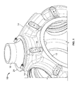
- a blade support tool 46 is installed on a blade collar 48 and locked into position by aligning one or more tool bayonets 50 of the blade support tool 46 with one or more complimentary blade bayonets 52 of the blade collar 48.
- a blade pin 54 is aligned with the hub opening 14, and the blade 16 is inserted into the hub opening 14.
- the installation operation is performed with the blade 16 in a substantially vertical orientation.
- the blade support tool 46 includes one or more support tabs 54 extending into contact with the hub 12 to support the blade 16 in the hub opening 14. At this point the inner race 28 and the outer race 30 of each bearing 18 are in alignment.
- the hub 12 includes a bearing port 56 at each bearing 18, which may include a port cover 58 (shown in FIG. 1 ).
- the port cover 58 is removed and the bearing balls 26 are inserted between the inner race 28 and outer race 30. Once the bearing balls 26 are in place, the port cover 58 is reinstalled.
- the blade support tool 46 is removed, and the blade 16 is now retained in the hub 12 by the bearings 18.
- the blade seal 20, backup ring 22 and seal support ring 24 are then installed.
- Removal of the blade 16 from the hub 12 is accomplished by merely reversing the above sequence of operations. Once the blade 16 is removed from the hub 12, inspection and/or rework can be performed on the inner race 28 and/or outer race 30 due to wear on the surfaces throughout the life of the assembly.
- the inner race 28 and outer race 30 can be reworked by removing a desired amount of material therefrom via machining, grinding, or other operation. Once the material is removed, the blade 16 may be reinstalled in the hub 12 via the above process, but in some embodiments with bearing necklaces having larger diameter bearing balls 26, depending on the amount of material removed via the rework.
- the blade 16 retention scheme described herein increases load capacity for a given bearing size over standard non-preloaded bearings, thereby allowing for a reduction in bearing size which results in a reduction of total propeller weight. Further, the blades 16 are easily individually removed and/or replaced in service, due at least in part to reduction in part count and complexity. Also, the bearing race surfaces are completely repairable to remove surface wear and damage thereby extending their useful life.
Landscapes
- Engineering & Computer Science (AREA)
- General Engineering & Computer Science (AREA)
- Mechanical Engineering (AREA)
- Aviation & Aerospace Engineering (AREA)
- Rolling Contact Bearings (AREA)
Claims (9)
- Procédé de montage d'une pale d'hélice (16) à un agencement d'hélice (10), comprenant :la fixation d'un outil de soutien de pale (46) à la pale d'hélice (16) ;l'insertion de la pale d'hélice (16) dans une ouverture de moyeu (14) d'un moyeu d'hélice (12) ;le fait de porter une partie de l'outil de soutien de pale (46) en contact avec le moyeu d'hélice (12), afin d'aligner une course intérieure de palier (28) située au niveau de la pale d'hélice (16) avec une course extérieure de palier (30) située au niveau du moyeu d'hélice (12) ;l'installation d'une pluralité de billes de palier (26) à travers un orifice de palier (56) et entre la course intérieure (28) et la course extérieure (30) ; etle retrait de l'outil de soutien de pale (46), ce qui permet de retenir la pale d'hélice (16) au niveau du moyeu d'hélice (12) par les paliers (18).
- Procédé selon la revendication 1, dans lequel la fixation de l'outil de soutien de pale (46) à la pale d'hélice (16) comprend l'alignement d'au moins une baïonnette de pale (52) avec au moins une baïonnette d'outil (50).
- Procédé selon la revendication 1 ou 2, comprenant en outre l'installation d'un couvercle d'orifice (58) au-dessus de l'orifice de palier (56) une fois que les billes de palier (26) sont installées.
- Procédé selon la revendication 1, 2 ou 3, comprenant en outre l'installation d'un joint de pale (20) dans l'ouverture de moyeu, entre le moyeu d'hélice (12) et la pale d'hélice (16).
- Procédé selon la revendication 4, comprenant en outre l'installation d'une bague de retenue de joint (22) au-dessus du joint de pale (20), afin de retenir le joint de pale dans l'ouverture de moyeu (14).
- Procédé selon l'une quelconque des revendications 1 à 5, dans lequel la course extérieure de palier (30) comprend un premier rayon de course extérieure (38) et un deuxième rayon de course extérieure (40) différent du premier rayon de course extérieure, relié par un relief extérieur (66).
- Procédé selon la revendication 6, dans lequel le premier rayon de course extérieure (38) et le deuxième rayon de course extérieure (40) ne partagent aucun point central commun.
- Procédé selon l'une quelconque des revendications 1 à 7, dans lequel la course intérieure de palier (28) comprend un premier rayon de course intérieure (34) et un deuxième rayon de course intérieure (36) différent du premier rayon de course intérieure, relié par un relief intérieur (44).
- Procédé selon la revendication 8, dans lequel le premier rayon de course intérieure (34) et le deuxième rayon de course intérieure (36) ne partagent aucun point central commun.
Applications Claiming Priority (1)
| Application Number | Priority Date | Filing Date | Title |
|---|---|---|---|
| US13/172,302 US8801383B2 (en) | 2011-06-29 | 2011-06-29 | Ball bearing retention for propeller blade and method of assembly |
Publications (3)
| Publication Number | Publication Date |
|---|---|
| EP2540619A2 EP2540619A2 (fr) | 2013-01-02 |
| EP2540619A3 EP2540619A3 (fr) | 2013-05-01 |
| EP2540619B1 true EP2540619B1 (fr) | 2014-07-16 |
Family
ID=46466176
Family Applications (1)
| Application Number | Title | Priority Date | Filing Date |
|---|---|---|---|
| EP12174445.2A Active EP2540619B1 (fr) | 2011-06-29 | 2012-06-29 | Procédé de montage d'une pale d'hélice dans un agencement des pales d'hélice |
Country Status (3)
| Country | Link |
|---|---|
| US (1) | US8801383B2 (fr) |
| EP (1) | EP2540619B1 (fr) |
| CA (1) | CA2780500A1 (fr) |
Families Citing this family (5)
| Publication number | Priority date | Publication date | Assignee | Title |
|---|---|---|---|---|
| US9381996B2 (en) * | 2013-05-09 | 2016-07-05 | Hamilton Sundstrand Corporation | Split blade retention race with inner and outer chamfers |
| EP3257743B1 (fr) | 2016-06-14 | 2020-05-20 | Ratier-Figeac SAS | Pales d'hélice |
| WO2022018354A1 (fr) * | 2020-07-24 | 2022-01-27 | Safran Aircraft Engines | Système de commande du calage angulaire d'une aube d'helice pour une turbomachine d'aeronef |
| US11981418B2 (en) * | 2020-07-24 | 2024-05-14 | Safran Aircraft Engines | System for controlling the pitch setting of a propeller vane for an aircraft turbine engine |
| US11913408B1 (en) | 2023-04-17 | 2024-02-27 | General Electric Company | Trunnion-to-disk connection for an open fan configuration aircraft powerplant |
Family Cites Families (16)
| Publication number | Priority date | Publication date | Assignee | Title |
|---|---|---|---|---|
| US1587184A (en) * | 1921-01-17 | 1926-06-01 | Riebe August | Ball bearing |
| GB499932A (en) | 1938-05-03 | 1939-01-31 | Hans Reissner | Improvements in or relating to screw propellers, particularly for aircraft |
| GB811177A (en) | 1955-11-22 | 1959-04-02 | Vyzk A Zkusebni Letecky Ustav | A single-row ball bearing |
| US3490537A (en) * | 1967-04-17 | 1970-01-20 | United Aircraft Corp | Quick disconnect retention |
| DE3844191A1 (de) | 1988-12-29 | 1990-07-05 | Mtu Muenchen Gmbh | Schaufelfussbefestigung fuer eine fasertechnische rotorschaufel |
| US6015264A (en) * | 1997-08-15 | 2000-01-18 | United Technologies Corporation | Preloaded retention assembly for aircraft propeller blade retention |
| US6524008B1 (en) * | 1999-07-19 | 2003-02-25 | Nsk, Ltd. | Ball bearing |
| JP2001208081A (ja) * | 2000-01-31 | 2001-08-03 | Nsk Ltd | 単列深溝型ラジアル玉軸受 |
| JP2002005178A (ja) | 2000-06-23 | 2002-01-09 | Hiroshi Teramachi | ボールの軌道溝構造 |
| US6827496B2 (en) * | 2001-08-28 | 2004-12-07 | Koyo Seiko Co., Ltd. | Four-point contact ball bearing |
| US7325974B2 (en) * | 2001-09-18 | 2008-02-05 | Nsk Ltd. | Pulley rotation support apparatus |
| JP2003097564A (ja) * | 2001-09-25 | 2003-04-03 | Harmonic Drive Syst Ind Co Ltd | 4点接触ボールベアリング |
| CN100400907C (zh) * | 2002-02-20 | 2008-07-09 | 日本精工株式会社 | 用于压缩机皮带轮的转动支撑装置 |
| DE112006003836T5 (de) * | 2006-05-18 | 2009-02-19 | Hamilton Sundstrand Corporation, Windsor Locks | Reibungsarmer Kugelseparator für Propellerblatt-Kugellager |
| US8753088B2 (en) * | 2008-02-28 | 2014-06-17 | Textron Innovations Inc. | Propeller blade retention device |
| DE102010002748A1 (de) | 2010-03-11 | 2011-09-15 | Zf Friedrichshafen Ag | Wälzlageranordnung |
-
2011
- 2011-06-29 US US13/172,302 patent/US8801383B2/en active Active
-
2012
- 2012-06-19 CA CA2780500A patent/CA2780500A1/fr not_active Abandoned
- 2012-06-29 EP EP12174445.2A patent/EP2540619B1/fr active Active
Also Published As
| Publication number | Publication date |
|---|---|
| EP2540619A2 (fr) | 2013-01-02 |
| EP2540619A3 (fr) | 2013-05-01 |
| CA2780500A1 (fr) | 2012-12-29 |
| US20130004318A1 (en) | 2013-01-03 |
| US8801383B2 (en) | 2014-08-12 |
Similar Documents
| Publication | Publication Date | Title |
|---|---|---|
| EP2540619B1 (fr) | Procédé de montage d'une pale d'hélice dans un agencement des pales d'hélice | |
| EP2538036B1 (fr) | Ensemble de support de palier intégral avec ressort de centrage pour un moteur de turbine à gaz | |
| EP3163106B1 (fr) | Ressort de centrage d'un seul tenant et support de palier et procédé de support de plusieurs paliers amortis | |
| EP2871376B1 (fr) | Ensemble de palier pour application de machine hydraulique | |
| US10612586B2 (en) | Thrust bearing for a wind turbine | |
| US8167501B2 (en) | Separator for bearing assemblies with cyclic loads | |
| US9746027B2 (en) | Auxiliary bearing of the ball bearing type for a magnetically suspended rotor system | |
| US9115756B2 (en) | Replaceable axial journal for auxiliary bearings | |
| EP2871377B1 (fr) | Unité de palier pour une application de machine hydraulique | |
| JP2001514994A (ja) | 航空機用プロペラ羽根の取付保持のための予圧を付加した軸受アセンブリ | |
| US10288114B2 (en) | Tapered roller bearing | |
| EP2000404B1 (fr) | Système de rétention de pale d'hélice avec assemblages de cartouche de roulement à rouleaux coniques | |
| GB2542465B (en) | Propeller assemblies with a partial hub | |
| KR20170041758A (ko) | 스러스트 베어링 및 리테이너 | |
| EP2886894B1 (fr) | Dispositif mécanique comprenant un palier et un système de lubrification, machine de mise en oeuvre et procédé | |
| US20150152918A1 (en) | Bearing cage with a peripheral vibration damping ring | |
| US9957038B2 (en) | Propeller assemblies and propeller blade retention assembly | |
| US11674502B2 (en) | Bearing assembly of a rotor of a wind turbine | |
| EP3943767A1 (fr) | Roulement à billes angulaire, et élément de maintien pour roulement à billes angulaire | |
| CN105799415A (zh) | 轮轴承单元和运输安全方法 | |
| JP2018017382A (ja) | 玉軸受 |
Legal Events
| Date | Code | Title | Description |
|---|---|---|---|
| PUAI | Public reference made under article 153(3) epc to a published international application that has entered the european phase |
Free format text: ORIGINAL CODE: 0009012 |
|
| AK | Designated contracting states |
Kind code of ref document: A2 Designated state(s): AL AT BE BG CH CY CZ DE DK EE ES FI FR GB GR HR HU IE IS IT LI LT LU LV MC MK MT NL NO PL PT RO RS SE SI SK SM TR |
|
| AX | Request for extension of the european patent |
Extension state: BA ME |
|
| PUAL | Search report despatched |
Free format text: ORIGINAL CODE: 0009013 |
|
| AK | Designated contracting states |
Kind code of ref document: A3 Designated state(s): AL AT BE BG CH CY CZ DE DK EE ES FI FR GB GR HR HU IE IS IT LI LT LU LV MC MK MT NL NO PL PT RO RS SE SI SK SM TR |
|
| AX | Request for extension of the european patent |
Extension state: BA ME |
|
| RIC1 | Information provided on ipc code assigned before grant |
Ipc: F16C 19/16 20060101ALI20130325BHEP Ipc: B64C 11/04 20060101AFI20130325BHEP Ipc: F16C 33/58 20060101ALI20130325BHEP |
|
| 17P | Request for examination filed |
Effective date: 20131031 |
|
| RBV | Designated contracting states (corrected) |
Designated state(s): AL AT BE BG CH CY CZ DE DK EE ES FI FR GB GR HR HU IE IS IT LI LT LU LV MC MK MT NL NO PL PT RO RS SE SI SK SM TR |
|
| GRAP | Despatch of communication of intention to grant a patent |
Free format text: ORIGINAL CODE: EPIDOSNIGR1 |
|
| INTG | Intention to grant announced |
Effective date: 20140212 |
|
| GRAS | Grant fee paid |
Free format text: ORIGINAL CODE: EPIDOSNIGR3 |
|
| GRAA | (expected) grant |
Free format text: ORIGINAL CODE: 0009210 |
|
| AK | Designated contracting states |
Kind code of ref document: B1 Designated state(s): AL AT BE BG CH CY CZ DE DK EE ES FI FR GB GR HR HU IE IS IT LI LT LU LV MC MK MT NL NO PL PT RO RS SE SI SK SM TR |
|
| REG | Reference to a national code |
Ref country code: GB Ref legal event code: FG4D |
|
| REG | Reference to a national code |
Ref country code: CH Ref legal event code: EP |
|
| REG | Reference to a national code |
Ref country code: IE Ref legal event code: FG4D |
|
| REG | Reference to a national code |
Ref country code: AT Ref legal event code: REF Ref document number: 677440 Country of ref document: AT Kind code of ref document: T Effective date: 20140815 |
|
| REG | Reference to a national code |
Ref country code: DE Ref legal event code: R096 Ref document number: 602012002421 Country of ref document: DE Effective date: 20140904 |
|
| REG | Reference to a national code |
Ref country code: NL Ref legal event code: VDEP Effective date: 20140716 |
|
| REG | Reference to a national code |
Ref country code: AT Ref legal event code: MK05 Ref document number: 677440 Country of ref document: AT Kind code of ref document: T Effective date: 20140716 |
|
| REG | Reference to a national code |
Ref country code: LT Ref legal event code: MG4D |
|
| PG25 | Lapsed in a contracting state [announced via postgrant information from national office to epo] |
Ref country code: GR Free format text: LAPSE BECAUSE OF FAILURE TO SUBMIT A TRANSLATION OF THE DESCRIPTION OR TO PAY THE FEE WITHIN THE PRESCRIBED TIME-LIMIT Effective date: 20141017 Ref country code: NO Free format text: LAPSE BECAUSE OF FAILURE TO SUBMIT A TRANSLATION OF THE DESCRIPTION OR TO PAY THE FEE WITHIN THE PRESCRIBED TIME-LIMIT Effective date: 20141016 Ref country code: LT Free format text: LAPSE BECAUSE OF FAILURE TO SUBMIT A TRANSLATION OF THE DESCRIPTION OR TO PAY THE FEE WITHIN THE PRESCRIBED TIME-LIMIT Effective date: 20140716 Ref country code: SE Free format text: LAPSE BECAUSE OF FAILURE TO SUBMIT A TRANSLATION OF THE DESCRIPTION OR TO PAY THE FEE WITHIN THE PRESCRIBED TIME-LIMIT Effective date: 20140716 Ref country code: ES Free format text: LAPSE BECAUSE OF FAILURE TO SUBMIT A TRANSLATION OF THE DESCRIPTION OR TO PAY THE FEE WITHIN THE PRESCRIBED TIME-LIMIT Effective date: 20140716 Ref country code: PT Free format text: LAPSE BECAUSE OF FAILURE TO SUBMIT A TRANSLATION OF THE DESCRIPTION OR TO PAY THE FEE WITHIN THE PRESCRIBED TIME-LIMIT Effective date: 20141117 Ref country code: FI Free format text: LAPSE BECAUSE OF FAILURE TO SUBMIT A TRANSLATION OF THE DESCRIPTION OR TO PAY THE FEE WITHIN THE PRESCRIBED TIME-LIMIT Effective date: 20140716 Ref country code: BG Free format text: LAPSE BECAUSE OF FAILURE TO SUBMIT A TRANSLATION OF THE DESCRIPTION OR TO PAY THE FEE WITHIN THE PRESCRIBED TIME-LIMIT Effective date: 20141016 |
|
| PG25 | Lapsed in a contracting state [announced via postgrant information from national office to epo] |
Ref country code: LV Free format text: LAPSE BECAUSE OF FAILURE TO SUBMIT A TRANSLATION OF THE DESCRIPTION OR TO PAY THE FEE WITHIN THE PRESCRIBED TIME-LIMIT Effective date: 20140716 Ref country code: NL Free format text: LAPSE BECAUSE OF FAILURE TO SUBMIT A TRANSLATION OF THE DESCRIPTION OR TO PAY THE FEE WITHIN THE PRESCRIBED TIME-LIMIT Effective date: 20140716 Ref country code: CY Free format text: LAPSE BECAUSE OF FAILURE TO SUBMIT A TRANSLATION OF THE DESCRIPTION OR TO PAY THE FEE WITHIN THE PRESCRIBED TIME-LIMIT Effective date: 20140716 Ref country code: PL Free format text: LAPSE BECAUSE OF FAILURE TO SUBMIT A TRANSLATION OF THE DESCRIPTION OR TO PAY THE FEE WITHIN THE PRESCRIBED TIME-LIMIT Effective date: 20140716 Ref country code: AT Free format text: LAPSE BECAUSE OF FAILURE TO SUBMIT A TRANSLATION OF THE DESCRIPTION OR TO PAY THE FEE WITHIN THE PRESCRIBED TIME-LIMIT Effective date: 20140716 Ref country code: RS Free format text: LAPSE BECAUSE OF FAILURE TO SUBMIT A TRANSLATION OF THE DESCRIPTION OR TO PAY THE FEE WITHIN THE PRESCRIBED TIME-LIMIT Effective date: 20140716 Ref country code: IS Free format text: LAPSE BECAUSE OF FAILURE TO SUBMIT A TRANSLATION OF THE DESCRIPTION OR TO PAY THE FEE WITHIN THE PRESCRIBED TIME-LIMIT Effective date: 20141116 |
|
| REG | Reference to a national code |
Ref country code: DE Ref legal event code: R097 Ref document number: 602012002421 Country of ref document: DE |
|
| PG25 | Lapsed in a contracting state [announced via postgrant information from national office to epo] |
Ref country code: DK Free format text: LAPSE BECAUSE OF FAILURE TO SUBMIT A TRANSLATION OF THE DESCRIPTION OR TO PAY THE FEE WITHIN THE PRESCRIBED TIME-LIMIT Effective date: 20140716 Ref country code: EE Free format text: LAPSE BECAUSE OF FAILURE TO SUBMIT A TRANSLATION OF THE DESCRIPTION OR TO PAY THE FEE WITHIN THE PRESCRIBED TIME-LIMIT Effective date: 20140716 Ref country code: IT Free format text: LAPSE BECAUSE OF FAILURE TO SUBMIT A TRANSLATION OF THE DESCRIPTION OR TO PAY THE FEE WITHIN THE PRESCRIBED TIME-LIMIT Effective date: 20140716 Ref country code: CZ Free format text: LAPSE BECAUSE OF FAILURE TO SUBMIT A TRANSLATION OF THE DESCRIPTION OR TO PAY THE FEE WITHIN THE PRESCRIBED TIME-LIMIT Effective date: 20140716 Ref country code: SK Free format text: LAPSE BECAUSE OF FAILURE TO SUBMIT A TRANSLATION OF THE DESCRIPTION OR TO PAY THE FEE WITHIN THE PRESCRIBED TIME-LIMIT Effective date: 20140716 Ref country code: RO Free format text: LAPSE BECAUSE OF FAILURE TO SUBMIT A TRANSLATION OF THE DESCRIPTION OR TO PAY THE FEE WITHIN THE PRESCRIBED TIME-LIMIT Effective date: 20140716 |
|
| PLBE | No opposition filed within time limit |
Free format text: ORIGINAL CODE: 0009261 |
|
| STAA | Information on the status of an ep patent application or granted ep patent |
Free format text: STATUS: NO OPPOSITION FILED WITHIN TIME LIMIT |
|
| REG | Reference to a national code |
Ref country code: FR Ref legal event code: PLFP Year of fee payment: 4 |
|
| 26N | No opposition filed |
Effective date: 20150417 |
|
| PG25 | Lapsed in a contracting state [announced via postgrant information from national office to epo] |
Ref country code: SI Free format text: LAPSE BECAUSE OF FAILURE TO SUBMIT A TRANSLATION OF THE DESCRIPTION OR TO PAY THE FEE WITHIN THE PRESCRIBED TIME-LIMIT Effective date: 20140716 |
|
| REG | Reference to a national code |
Ref country code: DE Ref legal event code: R119 Ref document number: 602012002421 Country of ref document: DE |
|
| PG25 | Lapsed in a contracting state [announced via postgrant information from national office to epo] |
Ref country code: MC Free format text: LAPSE BECAUSE OF FAILURE TO SUBMIT A TRANSLATION OF THE DESCRIPTION OR TO PAY THE FEE WITHIN THE PRESCRIBED TIME-LIMIT Effective date: 20140716 |
|
| REG | Reference to a national code |
Ref country code: CH Ref legal event code: PL |
|
| PG25 | Lapsed in a contracting state [announced via postgrant information from national office to epo] |
Ref country code: LU Free format text: LAPSE BECAUSE OF FAILURE TO SUBMIT A TRANSLATION OF THE DESCRIPTION OR TO PAY THE FEE WITHIN THE PRESCRIBED TIME-LIMIT Effective date: 20150629 |
|
| REG | Reference to a national code |
Ref country code: IE Ref legal event code: MM4A |
|
| PG25 | Lapsed in a contracting state [announced via postgrant information from national office to epo] |
Ref country code: DE Free format text: LAPSE BECAUSE OF NON-PAYMENT OF DUE FEES Effective date: 20160101 Ref country code: LI Free format text: LAPSE BECAUSE OF NON-PAYMENT OF DUE FEES Effective date: 20150630 Ref country code: IE Free format text: LAPSE BECAUSE OF NON-PAYMENT OF DUE FEES Effective date: 20150629 Ref country code: CH Free format text: LAPSE BECAUSE OF NON-PAYMENT OF DUE FEES Effective date: 20150630 |
|
| REG | Reference to a national code |
Ref country code: FR Ref legal event code: PLFP Year of fee payment: 5 |
|
| PG25 | Lapsed in a contracting state [announced via postgrant information from national office to epo] |
Ref country code: BE Free format text: LAPSE BECAUSE OF FAILURE TO SUBMIT A TRANSLATION OF THE DESCRIPTION OR TO PAY THE FEE WITHIN THE PRESCRIBED TIME-LIMIT Effective date: 20140716 |
|
| PG25 | Lapsed in a contracting state [announced via postgrant information from national office to epo] |
Ref country code: MT Free format text: LAPSE BECAUSE OF FAILURE TO SUBMIT A TRANSLATION OF THE DESCRIPTION OR TO PAY THE FEE WITHIN THE PRESCRIBED TIME-LIMIT Effective date: 20140716 |
|
| REG | Reference to a national code |
Ref country code: FR Ref legal event code: PLFP Year of fee payment: 6 |
|
| PG25 | Lapsed in a contracting state [announced via postgrant information from national office to epo] |
Ref country code: HU Free format text: LAPSE BECAUSE OF FAILURE TO SUBMIT A TRANSLATION OF THE DESCRIPTION OR TO PAY THE FEE WITHIN THE PRESCRIBED TIME-LIMIT; INVALID AB INITIO Effective date: 20120629 Ref country code: SM Free format text: LAPSE BECAUSE OF FAILURE TO SUBMIT A TRANSLATION OF THE DESCRIPTION OR TO PAY THE FEE WITHIN THE PRESCRIBED TIME-LIMIT Effective date: 20140716 |
|
| PG25 | Lapsed in a contracting state [announced via postgrant information from national office to epo] |
Ref country code: HR Free format text: LAPSE BECAUSE OF FAILURE TO SUBMIT A TRANSLATION OF THE DESCRIPTION OR TO PAY THE FEE WITHIN THE PRESCRIBED TIME-LIMIT Effective date: 20140716 |
|
| PG25 | Lapsed in a contracting state [announced via postgrant information from national office to epo] |
Ref country code: TR Free format text: LAPSE BECAUSE OF FAILURE TO SUBMIT A TRANSLATION OF THE DESCRIPTION OR TO PAY THE FEE WITHIN THE PRESCRIBED TIME-LIMIT Effective date: 20140716 |
|
| REG | Reference to a national code |
Ref country code: FR Ref legal event code: PLFP Year of fee payment: 7 |
|
| PG25 | Lapsed in a contracting state [announced via postgrant information from national office to epo] |
Ref country code: MK Free format text: LAPSE BECAUSE OF FAILURE TO SUBMIT A TRANSLATION OF THE DESCRIPTION OR TO PAY THE FEE WITHIN THE PRESCRIBED TIME-LIMIT Effective date: 20140716 |
|
| PG25 | Lapsed in a contracting state [announced via postgrant information from national office to epo] |
Ref country code: AL Free format text: LAPSE BECAUSE OF FAILURE TO SUBMIT A TRANSLATION OF THE DESCRIPTION OR TO PAY THE FEE WITHIN THE PRESCRIBED TIME-LIMIT Effective date: 20140716 |
|
| P01 | Opt-out of the competence of the unified patent court (upc) registered |
Effective date: 20230522 |
|
| PGFP | Annual fee paid to national office [announced via postgrant information from national office to epo] |
Ref country code: FR Payment date: 20230523 Year of fee payment: 12 |
|
| PGFP | Annual fee paid to national office [announced via postgrant information from national office to epo] |
Ref country code: GB Payment date: 20230523 Year of fee payment: 12 |