EP2539552B1 - Device for variably adjusting the control times of gas exchange valves of an internal combustion engine - Google Patents
Device for variably adjusting the control times of gas exchange valves of an internal combustion engine Download PDFInfo
- Publication number
- EP2539552B1 EP2539552B1 EP11701503.2A EP11701503A EP2539552B1 EP 2539552 B1 EP2539552 B1 EP 2539552B1 EP 11701503 A EP11701503 A EP 11701503A EP 2539552 B1 EP2539552 B1 EP 2539552B1
- Authority
- EP
- European Patent Office
- Prior art keywords
- drive
- spring
- internal combustion
- protuberance
- combustion engine
- Prior art date
- Legal status (The legal status is an assumption and is not a legal conclusion. Google has not performed a legal analysis and makes no representation as to the accuracy of the status listed.)
- Not-in-force
Links
- 238000002485 combustion reaction Methods 0.000 title claims abstract description 20
- 238000004804 winding Methods 0.000 claims description 5
- 239000000463 material Substances 0.000 claims description 3
- 230000002093 peripheral effect Effects 0.000 description 5
- 238000000034 method Methods 0.000 description 4
- 229910000831 Steel Inorganic materials 0.000 description 1
- 239000004809 Teflon Substances 0.000 description 1
- 229920006362 Teflon® Polymers 0.000 description 1
- 230000015572 biosynthetic process Effects 0.000 description 1
- 238000005266 casting Methods 0.000 description 1
- 230000007797 corrosion Effects 0.000 description 1
- 238000005260 corrosion Methods 0.000 description 1
- 230000008878 coupling Effects 0.000 description 1
- 238000010168 coupling process Methods 0.000 description 1
- 238000005859 coupling reaction Methods 0.000 description 1
- 238000013016 damping Methods 0.000 description 1
- 238000007598 dipping method Methods 0.000 description 1
- 238000005242 forging Methods 0.000 description 1
- 238000001746 injection moulding Methods 0.000 description 1
- 238000003780 insertion Methods 0.000 description 1
- 230000037431 insertion Effects 0.000 description 1
- 239000000314 lubricant Substances 0.000 description 1
- 230000001404 mediated effect Effects 0.000 description 1
- 239000002184 metal Substances 0.000 description 1
- 230000010355 oscillation Effects 0.000 description 1
- 239000004033 plastic Substances 0.000 description 1
- 230000001681 protective effect Effects 0.000 description 1
- 238000005245 sintering Methods 0.000 description 1
- 125000006850 spacer group Chemical group 0.000 description 1
- 239000010959 steel Substances 0.000 description 1
- 238000011144 upstream manufacturing Methods 0.000 description 1
Images

Classifications
-
- F—MECHANICAL ENGINEERING; LIGHTING; HEATING; WEAPONS; BLASTING
- F01—MACHINES OR ENGINES IN GENERAL; ENGINE PLANTS IN GENERAL; STEAM ENGINES
- F01L—CYCLICALLY OPERATING VALVES FOR MACHINES OR ENGINES
- F01L1/00—Valve-gear or valve arrangements, e.g. lift-valve gear
- F01L1/34—Valve-gear or valve arrangements, e.g. lift-valve gear characterised by the provision of means for changing the timing of the valves without changing the duration of opening and without affecting the magnitude of the valve lift
- F01L1/344—Valve-gear or valve arrangements, e.g. lift-valve gear characterised by the provision of means for changing the timing of the valves without changing the duration of opening and without affecting the magnitude of the valve lift changing the angular relationship between crankshaft and camshaft, e.g. using helicoidal gear
- F01L1/3442—Valve-gear or valve arrangements, e.g. lift-valve gear characterised by the provision of means for changing the timing of the valves without changing the duration of opening and without affecting the magnitude of the valve lift changing the angular relationship between crankshaft and camshaft, e.g. using helicoidal gear using hydraulic chambers with variable volume to transmit the rotating force
-
- F—MECHANICAL ENGINEERING; LIGHTING; HEATING; WEAPONS; BLASTING
- F01—MACHINES OR ENGINES IN GENERAL; ENGINE PLANTS IN GENERAL; STEAM ENGINES
- F01L—CYCLICALLY OPERATING VALVES FOR MACHINES OR ENGINES
- F01L1/00—Valve-gear or valve arrangements, e.g. lift-valve gear
- F01L1/34—Valve-gear or valve arrangements, e.g. lift-valve gear characterised by the provision of means for changing the timing of the valves without changing the duration of opening and without affecting the magnitude of the valve lift
- F01L1/344—Valve-gear or valve arrangements, e.g. lift-valve gear characterised by the provision of means for changing the timing of the valves without changing the duration of opening and without affecting the magnitude of the valve lift changing the angular relationship between crankshaft and camshaft, e.g. using helicoidal gear
-
- F—MECHANICAL ENGINEERING; LIGHTING; HEATING; WEAPONS; BLASTING
- F01—MACHINES OR ENGINES IN GENERAL; ENGINE PLANTS IN GENERAL; STEAM ENGINES
- F01L—CYCLICALLY OPERATING VALVES FOR MACHINES OR ENGINES
- F01L1/00—Valve-gear or valve arrangements, e.g. lift-valve gear
- F01L1/34—Valve-gear or valve arrangements, e.g. lift-valve gear characterised by the provision of means for changing the timing of the valves without changing the duration of opening and without affecting the magnitude of the valve lift
- F01L1/344—Valve-gear or valve arrangements, e.g. lift-valve gear characterised by the provision of means for changing the timing of the valves without changing the duration of opening and without affecting the magnitude of the valve lift changing the angular relationship between crankshaft and camshaft, e.g. using helicoidal gear
- F01L1/3442—Valve-gear or valve arrangements, e.g. lift-valve gear characterised by the provision of means for changing the timing of the valves without changing the duration of opening and without affecting the magnitude of the valve lift changing the angular relationship between crankshaft and camshaft, e.g. using helicoidal gear using hydraulic chambers with variable volume to transmit the rotating force
- F01L2001/3445—Details relating to the hydraulic means for changing the angular relationship
- F01L2001/34479—Sealing of phaser devices
-
- F—MECHANICAL ENGINEERING; LIGHTING; HEATING; WEAPONS; BLASTING
- F01—MACHINES OR ENGINES IN GENERAL; ENGINE PLANTS IN GENERAL; STEAM ENGINES
- F01L—CYCLICALLY OPERATING VALVES FOR MACHINES OR ENGINES
- F01L1/00—Valve-gear or valve arrangements, e.g. lift-valve gear
- F01L1/34—Valve-gear or valve arrangements, e.g. lift-valve gear characterised by the provision of means for changing the timing of the valves without changing the duration of opening and without affecting the magnitude of the valve lift
- F01L1/344—Valve-gear or valve arrangements, e.g. lift-valve gear characterised by the provision of means for changing the timing of the valves without changing the duration of opening and without affecting the magnitude of the valve lift changing the angular relationship between crankshaft and camshaft, e.g. using helicoidal gear
- F01L1/3442—Valve-gear or valve arrangements, e.g. lift-valve gear characterised by the provision of means for changing the timing of the valves without changing the duration of opening and without affecting the magnitude of the valve lift changing the angular relationship between crankshaft and camshaft, e.g. using helicoidal gear using hydraulic chambers with variable volume to transmit the rotating force
- F01L2001/3445—Details relating to the hydraulic means for changing the angular relationship
- F01L2001/34483—Phaser return springs
Definitions
- the invention relates to a device for the variable adjustment of the timing of gas exchange valves of an internal combustion engine with a drive element, an output element and at least one side cover, wherein the drive element can be brought into drive connection with a crankshaft of the internal combustion engine, wherein the output element can be brought into drive connection with a camshaft of the internal combustion engine and is arranged pivotably to the drive element, wherein the side cover is arranged on an axial side surface of the output element or the drive element and rotatably connected to the drive element or the driven element, wherein on the side facing away from the input and the driven element side of the side cover, a spring element is arranged and wherein the side cover has a disc-shaped portion from which protrude a plurality of fastening elements in the axial direction, which angeo on the side facing away from the drive element of the side cover rdnet are.
- devices for variable adjustment of the timing of gas exchange valves are used to adjust the phase relation between a crankshaft and a camshaft in a defined angular range, between a maximum early and a maximum late position variable.
- the device is integrated in a drive train via which torque is transmitted from the crankshaft to the camshaft.
- This powertrain can be used, for example, as belt, chain or gear drive to be realized.
- the device is non-rotatably connected to a camshaft and, for example, have one or more pressure chambers, by means of which the phase relation between the crankshaft and the camshaft can be selectively changed by pressure medium.
- Such a device is for example from the DE 10 2008 017 688 A1 known.
- the device has a drive element, an output element and two side covers, wherein the drive element is in driving connection with a crankshaft and the output element is non-rotatably attached to a camshaft.
- the output element is arranged in a defined angular interval pivotally to the drive element.
- the drive element, the output element and the side cover define a plurality of pressure chambers, which form a hydraulic actuator by means of which the phase angle between the output element and the drive element can be variably adjusted.
- the side covers are arranged on the axial side surfaces of the output element and the drive element and rotatably connected by screws with the drive element. The screws pass through the first side cover and the drive element and engage in each case a clamping nut, which are manufactured separately from the side cover and inextricably linked thereto.
- fastening element are integrally formed with the side cover.
- the fasteners are designed as cylindrical collars, which are provided with an internal thread and protrude in the axial direction of the side cover.
- the present invention has for its object to propose a device with increased life and reliability.
- the disc-shaped portion on the spring element facing side surface has at least one bulge, which faces at least one spring coil of the spring element in the axial direction of the device.
- the device has a drive element and an output element, wherein the drive element is driven by a crankshaft of the internal combustion engine and the output element drives a camshaft of the internal combustion engine.
- the drive element can be in drive connection with the crankshaft, for example, by means of a traction mechanism or gear drive.
- the output member may be rotatably connected to the camshaft, for example.
- an actuator for example a hydraulic actuator with at least two counteracting pressure chambers, provided by means of which the output element can be pivoted in a defined angular range relative to the drive element.
- a phase relation between the output element and the drive element is variably adjustable.
- a side cover On an axial side surface of the drive element and / or the output element, a side cover is provided which is rotatably connected to one of these components.
- the side cover on a disc-shaped portion, optionally with a central opening, which seals, for example, the pressure chambers in the axial direction.
- fasteners protrude in the axial direction. These may be, for example, screw heads of screws or clamping nuts into which the screws engage.
- the connection between the side cover and the output element or the drive element can be produced.
- clamping nuts these can be firmly connected to the disc-shaped section before assembly of the side cover or be present as a separate component.
- the fastening elements are formed integrally with the disk-shaped section, for example as cylindrical collars, which are provided with an internal thread.
- the disk-shaped portion is preceded by a spring element which, for example, as a helical spring, in particular as a spiral spring, is formed, and on the one hand acts on the output element and on the other hand on the drive element.
- a spring element By means of the spring element, the output element is acted upon relative to the drive element with a torque which can be used, for example, to compensate for friction losses or to achieve a base position with insufficient pressure medium.
- the disc-shaped section on the side facing the spring element at least one bulge, which faces at least one spring coil of the spring element in the axial direction of the device.
- the bulge serves as a stop for the spring element. If the spring element is excited to axial vibrations, then it is true this on the spacer, whereby the vibration amplitudes are reduced. Thus, the vibration loads acting on the spring element decrease. Furthermore, the vibrations are damped. In addition, the rigidity of the disk-shaped portion is increased by the bulges.
- the extent of the bulge in the radial direction of the disc-shaped portion is formed such that each spring coil of the spring element of the bulge facing in the axial direction and thus each spring coil undergoes the desired damping.
- the bulge limits an axial movement of the spring coil such that it can not dip into a region radially within the fastening elements. Thus, it is prevented that the spring coil between the fasteners jammed and so off the function of the spring element or the spring element is damaged.
- the bulge is formed integrally with the disc-shaped portion.
- the disc-shaped section on the side facing away from the spring element has a recess in the region of the bulge.
- the bulge is thus formed groove-shaped on the disc-shaped portion.
- the device has pressure chambers which are separated by vanes and projections, that the depression is arranged in the region of the pressure chambers, vanes and projections and that components of the group of vanes and projections are pivotable relative to the depression, wherein the recess is arranged outside the pivoting range of the pivotable components.
- a short circuit between two adjacent pressure chambers is effectively prevented via the recess.
- a plurality of groove-shaped bulges are provided, communicate the wells on the one hand with a pressure medium line and on the other hand in each case with a pressure chamber.
- the wells can be used to supply pressure to the pressure chambers.
- the recess may also be formed as a backdrop of a Verrieglungsmechanismus in which engages a locking element to produce a releasable mechanical locking between the drive element and the output element.
- an insert may be provided in the recess to avoid hydraulic short circuits between the pressure chambers.
- the insert may be formed as a sliding element.
- the bulge is massive, i. as excess material on the spring element facing side of the disc-shaped portion is formed. This can be formed integrally with the disk-shaped portion, or manufactured separately for this and force, positively or materially secured thereto.
- the bulge projects beyond the fastening elements in the axial direction at least in places or flush with them.
- the first side cover can, for example, by means of non-cutting forming process, for example a deep drawing process, by means of a sintering process, a metal or plastic injection molding process, by casting, forging or stamping package.
- the bulges can be provided with friction-reducing layers or corrosion protection layers or covered with a jacket of a sliding or protective material.
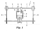
- FIG. 1 schematically an internal combustion engine 1 is sketched, wherein a seated on a crankshaft 2 piston 3 is indicated in a cylinder 4.
- the crankshaft 2 is in the illustrated embodiment via a respective traction drive 5 with an intake camshaft 6 and exhaust camshaft 7 in combination, wherein a first and a second device 11 for the variable adjustment of the timing of gas exchange valves 9, 10 for a relative rotation between the crankshaft 2 and the camshafts 6, 7 can provide.
- Cams 8 of the camshafts 6, 7 actuate one or more intake gas exchange valves 9 or one or more exhaust gas exchange valves 10.
- FIGS. 2 and 3 show a device 11 according to the invention in the longitudinal or cross section.
- the device 11 has a drive element 13, an output element 14 and two side covers 15, 16, which are arranged on axial side surfaces of the drive member 13 and secured by screws 12 thereto.
- the output element 14 is designed in the form of an impeller and has a substantially cylindrically designed hub member 17, extending from the outer cylindrical surface area wings 18 in the radial direction outwards.
- projections 20 extend radially inwards.
- the projections 20 are formed integrally with the peripheral wall 19.
- the drive element 13 is mounted by means of radially inner circumferential walls of the projections 20 relative to the output element 14 rotatably mounted on this.
- the drive element 13 is provided with a sprocket 21, via which by means of a chain drive, not shown, torque can be transmitted from the crankshaft 2 to the drive member 13.
- the output member 14 is rotatably connected in the assembled state with the camshaft, not shown in these figures, rotatably connected.
- a pressure chamber 22 is formed between each two circumferentially adjacent projections 20.
- Each of the pressure chambers 22 is circumferentially bounded by adjacent projections 20, axially of the side covers 15, 16, radially inwardly of the hub member 17, and radially outward of the peripheral wall 19.
- In each of the pressure chambers 22 protrudes a wing 18, wherein the wings 18 rest against both the side covers 15, 16, and on the peripheral wall 19.
- Each wing 18 thus divides the respective pressure chamber 22 into two oppositely acting pressure chambers.
- phase position of the drive element 13 to the output element 14 and thus the phase angle of the camshaft 6, 7 to the crankshaft 2 can be varied.
- phase position can be kept constant.
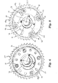
- FIGS. 4 and 5 show a plan view of the device 11 along the arrow IV FIG. 2 , where in FIG. 5 a spring cover 34 is not shown.
- the side cover 15 has a disk-shaped portion 23 and four fastening elements 24 and consists of a steel sheet.
- the fastening elements 24 are designed in the form of clamping nuts, which are fastened in a form-fitting manner in openings 33 of the disk-shaped section 23.
- the clamping nuts 24 protrude in the axial direction from the side surface of the disk-shaped section 23 facing away from the drive element 13.
- the clamping nuts 24 are each provided with an internal thread into which the screws 12 engage such that the rotationally fixed connection between the side covers 15, 16 and the drive element 13 is made.
- two of the four screws 12 project out of the respective clamping nut 24 in the axial direction.
- the length of the other screws 12 is chosen such that they do not protrude from the clamping nuts 24 in the assembled state.
- a biased spring element 25 ( Figures 2 and 4) is provided in the form of a coil spring.
- the coil spring is encompassed by a spring cover 34 and has a plurality of concentric spring coils 26 of different diameters.
- an end of the outermost spring coil 26 engages on the area protruding from the clamping nut 24 region of the first screw 12a ( FIG. 3 ).
- the outermost spring winding 26 is radially supported by the region of the second screw 12b protruding from the clamping nut 24.
- One end of the innermost spring coil 26 engages a protruding from the output member 14 Pin 27 on.
- the innermost spring coil 26 is supported radially inwardly on two further pins 27 projecting from the driven element 14.
- the biased spring element 25 is connected to both the drive member 13 and the output member 14 such that a torque between these components is mediated. This can serve, for example, to adjust the output element 14 in the case of insufficient supply of pressure medium to the device 11 in a base position or to adjust different adjustment speeds in the direction of earlier or later control times of the gas exchange valves 9, 10.
- the spring element 25 is excited to axial and radial vibrations, whereby individual spring coils 26 can dip into the region between the fastening elements 24.
- the dipping spring coil 26 is clamped between the fasteners 24, whereby the function of the device 11 is limited.
- increased wear on the spring element 25 occurs, and there is a risk that the spring element 25 breaks due to the increased load.
- five recesses 28 are provided on the disk-shaped portion 23, which extend in the direction of the spring element 25.
- the bulges 28 are formed by means of a chipless forming process, so that on the first side cover 15 recesses 29 are formed on the output member 14 side facing.
- Three first recesses 29 a are arranged in the region of pressure chambers 22 outside a pivoting range of the corresponding blade 18.
- a second recess 29b is arranged in a pivoting region of a wing 18, wherein the extension of the recess 29b in the circumferential direction is chosen smaller than the corresponding extent of the wing 18.
- a third recess 29c is arranged in the region of one of the projections 20, wherein the extension of Recess 29c is selected smaller in the circumferential direction, as the corresponding extension of the projection 20. In this way, a hydraulic short circuit avoided between two adjacent pressure chambers.
- a loading member 30 is inserted into the second recess 29b to further reduce the leakage between the pressure chambers and to improve the sliding contact between the first side cover 15 and the output member 14.
- the bulges 28 are formed and arranged such that each spring coil 26 faces each bulge 28 in the axial direction.
- the bulges 28 prevent the spring coils 26 from entering the region between the clamping nuts 24.
- the vibration amplitude is reduced and dampens the vibration.
- damage to the spring member 25 is prevented and reduces the stress caused by the vibrations.
- the axial side surfaces of the bulges 28 may be provided with a friction-reducing layer, for example a Teflon layer, or a wear-resistant layer.
- the output element 14 has a receptacle 31, in which an unillustrated, axially displaceable locking pin is received.
- the disc-shaped portion 23 has a slotted portion 32, into which the locking pin can engage in a certain phase position of the output element 14 relative to the drive element 13 in order to form a releasable, mechanical coupling between these two components.
- the slide 32 also projects out of the disk-shaped portion 23 and can serve as an axial stop for the spring element 25 in addition to the bulges 28.
Landscapes
- Engineering & Computer Science (AREA)
- Mechanical Engineering (AREA)
- General Engineering & Computer Science (AREA)
- Valve Device For Special Equipments (AREA)
Abstract
Description
Die Erfindung betrifft eine Vorrichtung zur variablen Einstellung der Steuerzeiten von Gaswechselventilen einer Brennkraftmaschine mit einem Antriebselement, einem Abtriebselement und mindestens einem Seitendeckel, wobei das Antriebselement in Antriebsverbindung mit einer Kurbelwelle der Brennkraftmaschine bringbar ist, wobei das Abtriebselement in Antriebsverbindung mit einer Nockenwelle der Brennkraftmaschine bringbar ist und schwenkbar zu dem Antriebselement angeordnet ist, wobei der Seitendeckel an einer axialen Seitenfläche des Abtriebselements oder des Antriebselements angeordnet und drehfest mit dem Antriebselement oder dem Abtriebselement verbunden ist, wobei auf der dem An- und dem Abtriebselement abgewandten Seite des Seitendeckels ein Federelement angeordnet ist und wobei der Seitendeckel einen scheibenförmigen Abschnitt aufweist, aus dem mehrere Befestigungselemente in axialer Richtung hervorstehen, die auf der dem Antriebselement abgewandten Seite des Seitendeckels angeordnet sind.The invention relates to a device for the variable adjustment of the timing of gas exchange valves of an internal combustion engine with a drive element, an output element and at least one side cover, wherein the drive element can be brought into drive connection with a crankshaft of the internal combustion engine, wherein the output element can be brought into drive connection with a camshaft of the internal combustion engine and is arranged pivotably to the drive element, wherein the side cover is arranged on an axial side surface of the output element or the drive element and rotatably connected to the drive element or the driven element, wherein on the side facing away from the input and the driven element side of the side cover, a spring element is arranged and wherein the side cover has a disc-shaped portion from which protrude a plurality of fastening elements in the axial direction, which angeo on the side facing away from the drive element of the side cover rdnet are.
In modernen Brennkraftmaschinen werden Vorrichtungen zur variablen Einstellung der Steuerzeiten von Gaswechselventilen eingesetzt, um die Phasenrelation zwischen einer Kurbelwelle und einer Nockenwelle in einem definierten Winkelbereich, zwischen einer maximalen Früh- und einer maximalen Spätposition, variabel einstellen zu können. Die Vorrichtung ist in einen Antriebsstrang integriert, über welchen Drehmoment von der Kurbelwelle auf die Nockenwelle übertragen wird. Dieser Antriebsstrang kann beispielsweise als Riemen-, Ketten- oder Zahnradtrieb realisiert sein. Darüber hinaus ist die Vorrichtung drehfest mit einer Nockenwelle verbunden und kann beispielsweise eine oder mehrere Druckkammern aufweisen, mittels derer die Phasenrelation zwischen der Kurbelwelle und der Nockenwelle durch Druckmittelbeaufschlagung gezielt verändert werden kann.In modern internal combustion engines devices for variable adjustment of the timing of gas exchange valves are used to adjust the phase relation between a crankshaft and a camshaft in a defined angular range, between a maximum early and a maximum late position variable. The device is integrated in a drive train via which torque is transmitted from the crankshaft to the camshaft. This powertrain can be used, for example, as belt, chain or gear drive to be realized. In addition, the device is non-rotatably connected to a camshaft and, for example, have one or more pressure chambers, by means of which the phase relation between the crankshaft and the camshaft can be selectively changed by pressure medium.
Eine derartige Vorrichtung ist beispielsweise aus der
Aus der
Aus der
Aus der
Der vorliegenden Erfindung liegt die Aufgabe zugrunde, eine Vorrichtung mit erhöhter Lebensdauer und Zuverlässigkeit vorzuschlagen.The present invention has for its object to propose a device with increased life and reliability.
Die Aufgabe wird erfindungsgemäß dadurch gelöst, dass der scheibenförmige Abschnitt an der dem Federelement zugewandten Seitenfläche zumindest eine Ausbuchtung aufweist, die zumindest einer Federwindung des Federelements in axialer Richtung der Vorrichtung gegenübersteht.The object is achieved in that the disc-shaped portion on the spring element facing side surface has at least one bulge, which faces at least one spring coil of the spring element in the axial direction of the device.
Die Vorrichtung weist ein Antriebselement und ein Abtriebselement auf, wobei das Antriebselement von einer Kurbelwelle der Brennkraftmaschine angetrieben wird und das Abtriebselement eine Nockenwelle der Brennkraftmaschine antreibt. Das Antriebselement kann beispielsweise mittels eines Zugmittel- oder Zahnradtriebs in Antriebsverbindung mit der Kurbelwelle stehen. Das Abtriebselement kann beispielsweise drehfest mit der Nockenwelle verbunden sein. Des Weiteren ist ein Stellantrieb, beispielsweise ein hydraulischer Stellantrieb mit zumindest zwei gegeneinander wirkenden Druckkammern, vorgesehen, mittels dem das Abtriebselement in einem definierten Winkelbereich relativ zu dem Antriebselement verschwenkt werden kann. Somit ist eine Phasenrelation zwischen dem Abtriebselement und dem Antriebselement variabel einstellbar. An einer axialen Seitenfläche des Antriebselements und / oder des Abtriebselements ist ein Seitendeckel vorgesehen der drehfest mit einem dieser Bauteile verbunden ist. Dabei weist der Seitendeckel einen scheibenförmigen Abschnitt, gegebenenfalls mit einer zentralen Öffnung, auf, der beispielsweise die Druckkammern in axialer Richtung abdichtet. Aus der dem Abtriebselement bzw. dem Antriebselement abgewandten axialen Seitenfläche des Seitendeckels ragen Befestigungselemente in axialer Richtung heraus. Dabei kann es sich beispielsweise um Schraubenköpfe von Schrauben oder um Spannmuttern handeln, in die die Schrauben eingreifen. Mittels der Befestigungselemente kann die Verbindung zwischen dem Seitendeckel und dem Abtriebselement bzw. dem Antriebselement hergestellt werden. Im Falle von Spannmuttern können diese vor der Montage des Seitendeckels fest mit dem scheibenförmigen Abschnitt verbunden sein oder als separates Bauteil vorliegen. Ebenso denkbar sind Ausführungsformen, in denen die Befestigungselemente einteilig mit dem scheibenförmigen Abschnitt ausgebildet sind, beispielsweise als zylindrische Krägen, welche mit einem Innengewinde versehen sind.The device has a drive element and an output element, wherein the drive element is driven by a crankshaft of the internal combustion engine and the output element drives a camshaft of the internal combustion engine. The drive element can be in drive connection with the crankshaft, for example, by means of a traction mechanism or gear drive. The output member may be rotatably connected to the camshaft, for example. Furthermore, an actuator, for example a hydraulic actuator with at least two counteracting pressure chambers, provided by means of which the output element can be pivoted in a defined angular range relative to the drive element. Thus, a phase relation between the output element and the drive element is variably adjustable. On an axial side surface of the drive element and / or the output element, a side cover is provided which is rotatably connected to one of these components. In this case, the side cover on a disc-shaped portion, optionally with a central opening, which seals, for example, the pressure chambers in the axial direction. From the output element or the drive element facing away from the axial side surface of the side cover fasteners protrude in the axial direction. These may be, for example, screw heads of screws or clamping nuts into which the screws engage. By means of the fastening elements, the connection between the side cover and the output element or the drive element can be produced. In the case of clamping nuts, these can be firmly connected to the disc-shaped section before assembly of the side cover or be present as a separate component. Likewise conceivable are embodiments in which the fastening elements are formed integrally with the disk-shaped section, for example as cylindrical collars, which are provided with an internal thread.
Dem scheibenförmigen Abschnitt vorgelagert ist ein Federelement vorgesehen, welches beispielsweise als Schraubenfeder, insbesondere als Spiralfeder, ausgebildet ist, und einerseits an dem Abtriebselement und andererseits an dem Antriebselement angreift. Mittels des Federelements wird das Abtriebselement relativ zu dem Antriebselement mit einem Drehmoment beaufschlagt, welches beispielsweise zur Kompensation von Reibungsverlusten oder zum Erreichen einer Basisposition bei ungenügender Druckmittelbeaufschlagung genutzt werden kann.The disk-shaped portion is preceded by a spring element is provided which, for example, as a helical spring, in particular as a spiral spring, is formed, and on the one hand acts on the output element and on the other hand on the drive element. By means of the spring element, the output element is acted upon relative to the drive element with a torque which can be used, for example, to compensate for friction losses or to achieve a base position with insufficient pressure medium.
Wird das Federelement während des Betriebs der Brennkraftmaschine zu axialen Schwingungen angeregt, so besteht die Gefahr, dass das Federelement oder eine Windung des Federelements in den Bereich zwischen den Befestigungselementen eintaucht und dort verklemmt, wodurch die Funktion des Federelements außer Kraft gesetzt oder das Federelement geschädigt wird.If the spring element is excited to axial vibrations during operation of the internal combustion engine, there is a risk that the spring element or a turn of the spring element dips into the region between the fastening elements and jammed there, whereby the function of the spring element is disabled or the spring element is damaged ,
Um dies zu verhindern, weist der scheibenförmige Abschnitt an der dem Federelement zugewandten Seitenfläche zumindest eine Ausbuchtung auf, die zumindest einer Federwindung des Federelements in axialer Richtung der Vorrichtung gegenübersteht. Die Ausbuchtung dient als Anschlag für das Federelement. Wird das Federelement zu axialen Schwingungen angeregt, so trifft dieses auf das Abstandselement, wodurch die Schwingungsamplituden verringert werden. Somit sinken die auf das Federelement wirkenden Schwingungsbelastungen. Des Weiteren werden die Schwingungen gedämpft. Zusätzlich wird die Steifigkeit des scheibenförmigen Abschnitts durch die Ausbuchtungen erhöht.To prevent this, the disc-shaped section on the side facing the spring element at least one bulge, which faces at least one spring coil of the spring element in the axial direction of the device. The bulge serves as a stop for the spring element. If the spring element is excited to axial vibrations, then it is true this on the spacer, whereby the vibration amplitudes are reduced. Thus, the vibration loads acting on the spring element decrease. Furthermore, the vibrations are damped. In addition, the rigidity of the disk-shaped portion is increased by the bulges.
Vorteilhafterweise ist die Erstreckung der Ausbuchtung in radialer Richtung des scheibenförmigen Abschnitts derart ausgebildet ist, dass jede Federwindung des Federelements der Ausbuchtung in axialer Richtung gegenübersteht und somit jede Federwindung die gewünschte Dämpfung erfährt.Advantageously, the extent of the bulge in the radial direction of the disc-shaped portion is formed such that each spring coil of the spring element of the bulge facing in the axial direction and thus each spring coil undergoes the desired damping.
Darüber hinaus kann vorgesehen sein, dass die Ausbuchtung eine axiale Bewegung der Federwindung derart begrenzt, dass diese nicht in einen Bereich radial innerhalb der Befestigungselemente eintauchen kann. Somit wird verhindert, dass sich die Federwindung zwischen den Befestigungselementen verklemmt und so die Funktion des Federelements ausgeschaltet oder das Federelement beschädigt wird.In addition, it can be provided that the bulge limits an axial movement of the spring coil such that it can not dip into a region radially within the fastening elements. Thus, it is prevented that the spring coil between the fasteners jammed and so off the function of the spring element or the spring element is damaged.
In einer vorteilhaften Weiterbildung der Erfindung kann vorgesehen sein, dass die Ausbuchtung einteilig mit dem scheibenförmigen Abschnitt ausgebildet ist.In an advantageous embodiment of the invention can be provided that the bulge is formed integrally with the disc-shaped portion.
Denkbar ist beispielsweise, dass der scheibenförmige Abschnitt an der dem Federelement abgewandten Seite eine Vertiefung in dem Bereich der Ausbuchtung aufweist. Die Ausbuchtung ist somit nutförmig an dem scheibenförmigen Abschnitt ausgebildet.It is conceivable, for example, that the disc-shaped section on the side facing away from the spring element has a recess in the region of the bulge. The bulge is thus formed groove-shaped on the disc-shaped portion.
In diesem Fall kann vorgesehen sein, dass die Vorrichtung Druckkammern aufweist, die durch Flügel und Vorsprünge getrennt sind, dass die Vertiefung im Bereich der Druckkammern, Flügel und Vorsprünge angeordnet ist und dass Bauteile aus der Gruppe Flügel und Vorsprünge relativ zu der Vertiefung verschwenkbar sind, wobei die Vertiefung außerhalb des Schwenkbereichs der verschwenkbaren Bauteile angeordnet ist. Somit wird ein Kurzschluss zwischen zwei benachbarten Druckkammern über die Vertiefung wirkungsvoll unterbunden. Dabei kann vorgesehen sein, dass mehrere nutförmige Ausbuchtungen vorgesehen sind, deren Vertiefungen einerseits mit einer Druckmittelleitung und andererseits jeweils mit einer Druckkammer kommunizieren. Somit können die Vertiefungen zur Druckmittelversorgung der Druckkammern genutzt werden.In this case, it can be provided that the device has pressure chambers which are separated by vanes and projections, that the depression is arranged in the region of the pressure chambers, vanes and projections and that components of the group of vanes and projections are pivotable relative to the depression, wherein the recess is arranged outside the pivoting range of the pivotable components. Thus, a short circuit between two adjacent pressure chambers is effectively prevented via the recess. It can be provided that a plurality of groove-shaped bulges are provided, communicate the wells on the one hand with a pressure medium line and on the other hand in each case with a pressure chamber. Thus, the wells can be used to supply pressure to the pressure chambers.
Steht in den Vertiefungen Druckmittel an, so ergibt sich der zusätzliche Vorteil, dass bei einer Schwenkbewegung des scheibenförmigen Abschnitts relativ zu dem Abtriebselement oder dem Antriebselement den gegeneinander bewegten Flächen Schmiermittel zugeführt wird.If pressure medium is present in the depressions, there is the additional advantage that lubricant is supplied to the areas moved relative to one another during a pivoting movement of the disk-shaped section relative to the output element or the drive element.
Die Vertiefung kann darüber hinaus als Kulisse eines Verrieglungsmechanismus ausgebildet sein, in die ein Verriegelungselement eingreift um eine lösbare, mechanische Verriegelung zwischen dem Antriebselement und dem Abtriebselement herzustellen.The recess may also be formed as a backdrop of a Verrieglungsmechanismus in which engages a locking element to produce a releasable mechanical locking between the drive element and the output element.
Alternativ kann in der Vertiefung ein Einlegeteil vorgesehen sein um hydraulische Kurzschlüsse zwischen den Druckkammern zu vermeiden. Das Einlegeteil kann als Gleitelement ausgebildet sein.Alternatively, an insert may be provided in the recess to avoid hydraulic short circuits between the pressure chambers. The insert may be formed as a sliding element.
Alternativ zu der nutförmigen Ausformung der Ausbuchtung sind Ausführungsformen denkbar, in denen die Ausbuchtung massiv, d.h. als Materialüberschuss an der dem Federelement zugewandten Seite des scheibenförmigen Abschnitts, ausgebildet ist. Diese kann einteilig mit dem scheibenförmigen Abschnitt ausgebildet sein, oder separat zu diesem gefertigt und kraft-, form- oder stoffschlüssig an diesem befestigt sein.As an alternative to the groove-shaped formation of the bulge, embodiments are conceivable in which the bulge is massive, i. as excess material on the spring element facing side of the disc-shaped portion is formed. This can be formed integrally with the disk-shaped portion, or manufactured separately for this and force, positively or materially secured thereto.
Vorteilhafterweise überragt die Ausbuchtung die Befestigungselemente in axialer Richtung zumindest bereichsweise oder schließt bündig mit diesen ab.Advantageously, the bulge projects beyond the fastening elements in the axial direction at least in places or flush with them.
Der erste Seitendeckel kann beispielsweise mittels spanloser Umformverfahren, beispielsweise eines Tiefziehverfahrens, mittels eines Sinterverfahrens, eines Metall- oder Kunststoffspritzgussverfahrens, mittels Gießen, Schmieden oder Stanzpaketieren hergestellt werden. Die Ausbuchtungen können mit reibungsmindernden Schichten oder Korrosionsschutzschichten versehen sein oder mit einem Mantel eines Gleit- oder Schutzwerkstoffes abgedeckt sein.The first side cover can, for example, by means of non-cutting forming process, for example a deep drawing process, by means of a sintering process, a metal or plastic injection molding process, by casting, forging or stamping package. The bulges can be provided with friction-reducing layers or corrosion protection layers or covered with a jacket of a sliding or protective material.
Weitere Merkmale der Erfindung ergeben sich aus der nachfolgenden Beschreibung und aus den Zeichnungen in denen ein Ausführungsbeispiel der Erfindung vereinfacht dargestellt ist. Es zeigen:
- Figur 1
- nur sehr schematisch eine Brennkraftmaschine,
Figur 2- einen Längsschnitt durch eine erfindungsgemäßen Vorrichtung zur variablen Einstellung der Steuerzeiten von Gaswechselventilen einer Brennkraftmaschine,
- Figur 3
- einen Querschnitt durch die erfindungsgemäße Vorrichtung entlang der Linie III-III in
Figur 2 - Figur 4
- einen Draufsicht auf die Vorrichtung entlang des Pfeils IV in
Figur 2 Figur 5- eine Darstellung gemäß
Figur 4 , wobei ein Federdeckel nicht dargestellt ist.
- FIG. 1
- only very schematically an internal combustion engine,
- FIG. 2
- a longitudinal section through a device according to the invention for the variable adjustment of the timing of gas exchange valves of an internal combustion engine,
- FIG. 3
- a cross section through the device according to the invention along the line III-III in
FIG. 2 . - FIG. 4
- a plan view of the device along the arrow IV in
FIG. 2 . - FIG. 5
- a representation according to
FIG. 4 , wherein a spring cover is not shown.
In
Die
Ausgehend von einer äußeren Umfangswand 19 des Antriebselements 13 erstrecken sich Vorsprünge 20 radial nach innen. In der dargestellten Ausführungsform sind die Vorsprünge 20 einteilig mit der Umfangswand 19 ausgebildet. Das Antriebselement 13 ist mittels radial innen liegender Umfangswände der Vorsprünge 20 relativ zu dem Abtriebselement 14 drehbar auf diesem gelagert.Starting from an outer
Das Antriebselement 13 ist mit einem Kettenrad 21 versehen, über das mittels eines nicht dargestellten Kettentriebs Drehmoment von der Kurbelwelle 2 auf das Antriebselement 13 übertragen werden kann. Das Abtriebselement 14 ist im montierten Zustand drehfest mit der in diesen Figuren nicht dargestellten Nockenwelle drehfest verbunden.The
Innerhalb der Vorrichtung 11 ist zwischen jeweils zwei in Umfangsrichtung benachbarten Vorsprüngen 20 ein Druckraum 22 ausgebildet. Jeder der Druckräume 22 wird in Umfangsrichtung von benachbarten Vorsprünge 20, in axialer Richtung von den Seitendeckeln 15, 16, radial nach innen von dem Nabenelement 17 und radial nach außen von der Umfangswand 19 begrenzt. In jeden der Druckräume 22 ragt ein Flügel 18, wobei die Flügel 18 sowohl an den Seitendeckeln 15, 16, als auch an der Umfangswand 19 anliegen. Jeder Flügel 18 teilt somit den jeweiligen Druckraum 22 in zwei gegeneinander wirkende Druckkammern.Within the
Durch Druckbeaufschlagung einer Gruppe von Druckkammern und Druckentlastung der anderen Gruppe kann die Phasenlage des Antriebselements 13 zum Abtriebselement 14 und damit die Phasenlage der Nockenwelle 6, 7 zur Kurbelwelle 2 variiert werden. Durch Druckbeaufschlagung beider Gruppen von Druckkammern kann die Phasenlage konstant gehalten werden.By pressurizing a group of pressure chambers and depressurizing the other group, the phase position of the
Die
Den Spannmuttern 24 vorgelagert, ist ein vorgespanntes Federelement 25 (Figuren 2 und 4) in Form einer Spiralfeder vorgesehen. Die Spiralfeder wird von einem Federdeckel 34 umgriffen und weist mehrere konzentrische Federwindungen 26 unterschiedlichen Durchmessers auf. Dabei greift ein Ende der äußersten Federwindung 26 an dem aus der Spannmutter 24 herausragenden Bereich der ersten Schraube 12a an (
Während des Betriebs der Brennkraftmaschine 1 wird das Federelement 25 zu axialen und radialen Schwingungen angeregt, wodurch einzelne Federwindungen 26 in den Bereich zwischen den Befestigungselementen 24 eintauchen können. Neben einer Erhöhung der Reibung, besteht die Gefahr, dass die eintauchende Federwindung 26 zwischen den Befestigungselementen 24 eingeklemmt wird, wodurch die Funktion der Vorrichtung 11 eingeschränkt wird. Darüber hinaus tritt erhöhter Verschleiß an dem Federelement 25 auf, und es besteht die Gefahr, dass das Federelement 25 auf Grund der erhöhten Belastung bricht.During operation of the internal combustion engine 1, the
Um dies zu verhindern sind an dem scheibenförmigen Abschnitt 23 fünf Ausbuchtungen 28 vorgesehen, die sich in Richtung des Federelements 25 erstrecken. Die Ausbuchtungen 28 sind mittels eines spanlosen Umformverfahrens ausgeformt, so dass an dem ersten Seitendeckel 15 Vertiefungen 29 auf der dem Abtriebselement 14 zugewandten Seite ausgebildet sind. Drei erste Vertiefungen 29a sind im Bereich von Druckräumen 22 außerhalb eines Schwenkbereichs des korrespondierenden Flügels 18 angeordnet. Eine zweite Vertiefung 29b ist in einem Schwenkbereich eines Flügels 18 angeordnet, wobei die Erstreckung der Vertiefung 29b in Umfangsrichtung kleiner gewählt ist, als die korrespondierende Erstreckung des Flügels 18. Eine dritte Vertiefung 29c ist im Bereich eines der Vorsprünge 20 angeordnet, wobei die Erstreckung der Vertiefung 29c in Umfangsrichtung kleiner gewählt ist, als die korrespondierende Erstreckung des Vorsprungs 20. Auf diese Weise wird ein hydraulischer Kurzschluss zwischen zwei benachbarten Druckkammern vermieden. In die zweite Vertiefung 29b ist zusätzlich ein Einlegelement 30 eingebracht, um die Leckage zwischen den Druckkammern weiter zu verringern und den Gleitkontakt zwischen dem ersten Seitendeckel 15 und dem Abtriebselement 14 zu verbessern.To prevent this, five
Die Ausbuchtungen 28 sind derart ausgebildet und angeordnet, dass jede Federwindung 26 jeder Ausbuchtung 28 in axialer Richtung gegenübersteht.The
Werden die Federwindungen 26 des Federelements 25 während des Betriebs der Brennkraftmaschine 1 zu axialen Schwingungen angeregt, verhindern die Ausbuchtungen 28, dass die Federwindungen 26 in den Bereich zwischen den Spannmuttern 24 eintreten. Darüber hinaus wird die Schwingungsamplitude verringert und die Schwingung gedämpft. Somit wird eine Beschädigung des Federelements 25 verhindert und die durch die Schwingungen hervorgerufene Belastung verringert. Die axialen Seitenflächen der Ausbuchtungen 28 können mit einer reibungsmindernden Schicht, beispielsweise einer Teflonschicht, oder einer Verschleißschutzschicht versehen sein.If the spring coils 26 of the
Das Abtriebselement 14 weist eine Aufnahme 31 auf, in der ein nicht dargestellter, axial verschiebbarer Verriegelungspin aufgenommen ist. Der scheibenförmige Abschnitt 23 weist eine Kulisse 32 auf, in die der Verriegelungspin in einer bestimmten Phasenlage des Abtriebselements 14 relativ zu dem Antriebselement 13 eingreifen kann, um eine lösbare, mechanische Kopplung zwischen diesen beiden Bauteilen auszubilden. Die Kulisse 32 ragt ebenfalls aus dem scheibenförmigen Abschnitt 23 heraus und kann neben den Ausbuchtungen 28 als Axialanschlag für das Federelement 25 dienen.The
- 11
- BrennkraftmaschineInternal combustion engine
- 22
- Kurbelwellecrankshaft
- 33
- Kolbenpiston
- 44
- Zylindercylinder
- 55
- Zugmitteltriebtraction drive
- 66
- Einlassnockenwelleintake camshaft
- 77
- Auslassnockenwelleexhaust
- 88th
- Nockencam
- 99
- EinlassgaswechselventilInlet gas exchange valve
- 1010
- AuslassgaswechselventilAuslassgaswechselventil
- 1111
- Vorrichtungcontraption
- 1212
- Schraubescrew
- 1313
- Antriebselementdriving element
- 1414
- Abtriebselementoutput element
- 1515
- Seitendeckelside cover
- 1616
- Seitendeckelside cover
- 1717
- Nabenelementhub element
- 1818
- Flügelwing
- 1919
- Umfangswandperipheral wall
- 2020
- Vorsprunghead Start
- 2121
- KettenradSprocket
- 2222
- Druckraumpressure chamber
- 2323
- scheibenförmiger Abschnittdisc-shaped section
- 2424
- Befestigungselementfastener
- 2525
- Federelementspring element
- 2626
- Federwindungspring coil
- 2727
- Stiftpen
- 2828
- Ausbuchtungenbulges
- 29abc29abc
- Vertiefungdeepening
- 3030
- Einlegelementinsertion element
- 3131
- Aufnahmeadmission
- 3232
- Kulissescenery
- 3333
- Öffnungopening
- 3434
- Federdeckelspring cover
Claims (8)
- Device (11) for the variable adjustment of the timing of gas exchange valves (9, 10) of an internal combustion engine (1), having- a drive input element (13), a drive output element (14) and at least one side cover (15),- wherein the drive input element (13) can be drive-connected to a crankshaft (2) of the internal combustion engine (1),- wherein the drive output element (14) can be drive-connected to a camshaft (6, 7) of the internal combustion engine (1) and is arranged so as to be pivotable relative to the drive input element (13),- wherein the side cover (15) is arranged on an axial side surface of the drive output element (14) or of the drive input element (13) and is connected rotationally conjointly to the drive input element (13) or to the drive output element (14),- wherein a spring element (25) is arranged on that side of the side cover which faces away from the drive input and drive output elements (13, 14), and- wherein the side cover (15) has a disc-shaped section (23) from which multiple fastening elements (24) project in the axial direction, which fastening elements are arranged on that side of the side cover (15) which faces away from the drive input element (13), characterized in that- the disc-shaped section (23) has, on the side surface facing toward the spring element (25), at least one protuberance (28) which is situated opposite at least one spring winding (26) of the spring element (25) in the axial direction of the device (11).
- Device (11) according to Claim 1, characterized in that the protuberance (28) limits an axial movement of the spring winding (26) such that said spring winding cannot protrude into a region radially to the inside of the fastening elements (24).
- Device (11) according to Claim 1, characterized in that the protuberance (28) is formed in one piece with the disc-shaped section (23).
- Device (11) according to Claim 1, characterized in that the extent of the protuberance (28) in the radial direction of the disc-shaped section (23) is formed such that each spring winding (26) of the spring element (25) is situated opposite the protuberance (28) in the axial direction.
- Device (11) according to Claim 1, characterized in that, on the side facing away from the spring element (25), the disc-shaped section (23) has a depression (29) in the region of the protuberance (28).
- Device (11) according to Claim 5, characterized in that the device (11) has pressure chambers which are separated by vanes (18) and projections (20), in that the depression is arranged in the region of the pressure chambers, vanes (18) and projections (20), and in that components from the group comprising vanes (18) and projections (20) are pivotable relative to the depression (29), wherein the depression (29) is arranged outside the pivoting range of the pivotable components.
- Device (11) according to Claim 1, characterized in that the protuberance (28) is in the form of a surplus of material on that side of the disc-shaped section (23) which faces toward the spring element (25).
- Device (11) according to Claim 1, characterized in that the protuberance (28) projects beyond the fastening elements (24) in the axial direction at least in regions, or terminates flush with said fastening elements.
Applications Claiming Priority (2)
| Application Number | Priority Date | Filing Date | Title |
|---|---|---|---|
| DE102010009394A DE102010009394A1 (en) | 2010-02-26 | 2010-02-26 | Device for variably setting the control times of gas exchange valves of an internal combustion engine |
| PCT/EP2011/050972 WO2011104055A1 (en) | 2010-02-26 | 2011-01-25 | Device for variably adjusting the control times of gas exchange valves of an internal combustion engine |
Publications (2)
| Publication Number | Publication Date |
|---|---|
| EP2539552A1 EP2539552A1 (en) | 2013-01-02 |
| EP2539552B1 true EP2539552B1 (en) | 2013-12-18 |
Family
ID=44226000
Family Applications (1)
| Application Number | Title | Priority Date | Filing Date |
|---|---|---|---|
| EP11701503.2A Not-in-force EP2539552B1 (en) | 2010-02-26 | 2011-01-25 | Device for variably adjusting the control times of gas exchange valves of an internal combustion engine |
Country Status (6)
| Country | Link |
|---|---|
| US (1) | US8671900B2 (en) |
| EP (1) | EP2539552B1 (en) |
| KR (1) | KR20130008014A (en) |
| CN (1) | CN102791965B (en) |
| DE (1) | DE102010009394A1 (en) |
| WO (1) | WO2011104055A1 (en) |
Families Citing this family (10)
| Publication number | Priority date | Publication date | Assignee | Title |
|---|---|---|---|---|
| DE102010005602A1 (en) * | 2010-01-25 | 2011-07-28 | Schaeffler Technologies GmbH & Co. KG, 91074 | Phaser |
| DE102010008005A1 (en) * | 2010-02-15 | 2011-08-18 | Schaeffler Technologies GmbH & Co. KG, 91074 | Stator cover unit and camshaft adjuster |
| DE102011081971A1 (en) * | 2011-09-01 | 2013-03-07 | Schaeffler Technologies AG & Co. KG | Phaser |
| DE102011086236B4 (en) | 2011-11-14 | 2017-03-09 | Schaeffler Technologies AG & Co. KG | Connection between a spur gear and a toothed shaft of a camshaft adjusting unit |
| DE102012217393A1 (en) * | 2012-09-26 | 2014-03-27 | Schaeffler Technologies Gmbh & Co. Kg | Phaser |
| DE102013204659A1 (en) | 2013-03-18 | 2014-09-18 | Schaeffler Technologies Gmbh & Co. Kg | Phaser |
| US9879574B2 (en) * | 2014-02-14 | 2018-01-30 | Aisin Seiki Kabushiki Kaisha | Valve opening and closing timing control apparatus |
| CN105650241A (en) * | 2015-12-10 | 2016-06-08 | 刘元生 | Adjustable timing gear of engine |
| WO2021079396A1 (en) * | 2019-10-21 | 2021-04-29 | 三菱電機株式会社 | Valve timing adjustment device |
| US11560816B1 (en) | 2021-07-16 | 2023-01-24 | Schaeffler Technologies AG & Co. KG | Spring retainer retention tab for bias spring |
Family Cites Families (10)
| Publication number | Priority date | Publication date | Assignee | Title |
|---|---|---|---|---|
| US5095857A (en) | 1990-07-17 | 1992-03-17 | Eaton Corporation | Self actuator for cam phasers |
| DE19708661B4 (en) | 1997-03-04 | 2005-06-16 | Ina-Schaeffler Kg | Device for varying the valve timing of an internal combustion engine, in particular camshaft adjusting device according to the vane cell principle |
| DE10007200A1 (en) | 2000-02-17 | 2001-08-23 | Schaeffler Waelzlager Ohg | Device for changing the control times of gas exchange valves of an internal combustion engine |
| DE10215879A1 (en) * | 2002-04-11 | 2003-10-23 | Ina Schaeffler Kg | Device for changing the timing of gas exchange valves of an internal combustion engine, in particular a device for the hydraulic rotation angle adjustment of a camshaft relative to a crankshaft |
| US6619248B1 (en) * | 2002-04-17 | 2003-09-16 | Ina-Schaeffler Kg | Device for altering the control timing of gas exchange valves of an internal combustion engine, especially an apparatus for hydraulic rotational angle adjustment of a camshaft relative to a crankshaft |
| DE102005024241B4 (en) | 2005-05-23 | 2017-08-17 | Schaeffler Technologies AG & Co. KG | Device for the variable adjustment of the timing of gas exchange valves of an internal combustion engine |
| DE102006002993A1 (en) * | 2006-01-21 | 2007-08-09 | Schaeffler Kg | Camshaft adjuster for an internal combustion engine |
| DE102006036052B4 (en) | 2006-08-02 | 2018-03-08 | Schaeffler Technologies AG & Co. KG | Sealing plate for a camshaft adjuster and camshaft adjuster with a sealing plate |
| CN201110201Y (en) * | 2007-09-17 | 2008-09-03 | 靳宇男 | Interface distribution engine |
| DE102008017688A1 (en) | 2008-04-08 | 2009-10-15 | Schaeffler Kg | Device for the variable adjustment of the timing of gas exchange valves of an internal combustion engine |
-
2010
- 2010-02-26 DE DE102010009394A patent/DE102010009394A1/en not_active Withdrawn
-
2011
- 2011-01-25 KR KR1020127022118A patent/KR20130008014A/en not_active Withdrawn
- 2011-01-25 US US13/580,476 patent/US8671900B2/en not_active Expired - Fee Related
- 2011-01-25 EP EP11701503.2A patent/EP2539552B1/en not_active Not-in-force
- 2011-01-25 WO PCT/EP2011/050972 patent/WO2011104055A1/en not_active Ceased
- 2011-01-25 CN CN201180011322.0A patent/CN102791965B/en not_active Expired - Fee Related
Also Published As
| Publication number | Publication date |
|---|---|
| KR20130008014A (en) | 2013-01-21 |
| WO2011104055A1 (en) | 2011-09-01 |
| US20120318222A1 (en) | 2012-12-20 |
| CN102791965B (en) | 2014-10-29 |
| US8671900B2 (en) | 2014-03-18 |
| DE102010009394A1 (en) | 2011-09-01 |
| CN102791965A (en) | 2012-11-21 |
| EP2539552A1 (en) | 2013-01-02 |
Similar Documents
| Publication | Publication Date | Title |
|---|---|---|
| EP2539552B1 (en) | Device for variably adjusting the control times of gas exchange valves of an internal combustion engine | |
| DE102009050779B4 (en) | Schwenkmotornockenwellenversteller with a friction disc and mounting method | |
| EP2478192B1 (en) | Device for variably adjusting the control times of gas exchange valves of an internal combustion engine | |
| DE102012202520B4 (en) | Central valve for a camshaft adjuster | |
| DE102015008925B4 (en) | Valve train for engine | |
| EP2470757B1 (en) | Control valve | |
| DE102008050134B4 (en) | Camshaft adjustment device for an internal combustion engine | |
| DE102012204726A1 (en) | Phaser | |
| EP2539555B1 (en) | Device for variably adjusting the control times of gas exchange valves of an internal combustion engine | |
| DE102008052413A1 (en) | Valve gear of an internal combustion engine | |
| WO2010043462A1 (en) | Device for variably adjusting the valve timing of gas exchange valves of an internal combustion engine | |
| DE102012202823B4 (en) | Phaser | |
| DE102010008003A1 (en) | feeder | |
| WO2010006855A1 (en) | Device for variably adjusting the valve timing of gas exchange valves of an internal combustion engine | |
| DE102012203114A1 (en) | Insert for camshaft adjuster with central locking | |
| EP2362074B1 (en) | Device for variable valve timing on a combustion engine | |
| DE102015214623A1 (en) | Camshaft adjusting device | |
| DE102009051309B4 (en) | Device for the variable setting of the control times of gas exchange valves of an internal combustion engine | |
| DE202008018146U1 (en) | Device for adjusting the camshaft of internal combustion engines | |
| DE102015206700A1 (en) | Camshaft adjuster with an axial preload element | |
| DE102017109006A1 (en) | Phaser | |
| WO2010034575A1 (en) | Device for variably adjusting the valve timing of gas exchange valves of an internal combustion engine | |
| DE102014221417A1 (en) | Stator for camshaft adjuster with force receiving component formed thereon | |
| EP2313619A1 (en) | Device for variably adjusting the valve timing of gas exchange valves of an internal combustion engine | |
| DE102009030210A1 (en) | Device for variably adjusting control times of gas exchange valves of internal combustion engine, has side covers, belt pulleys and base body, which are made of plastic, where surface of body is partially provided with metal layer |
Legal Events
| Date | Code | Title | Description |
|---|---|---|---|
| PUAI | Public reference made under article 153(3) epc to a published international application that has entered the european phase |
Free format text: ORIGINAL CODE: 0009012 |
|
| 17P | Request for examination filed |
Effective date: 20120926 |
|
| AK | Designated contracting states |
Kind code of ref document: A1 Designated state(s): AL AT BE BG CH CY CZ DE DK EE ES FI FR GB GR HR HU IE IS IT LI LT LU LV MC MK MT NL NO PL PT RO RS SE SI SK SM TR |
|
| DAX | Request for extension of the european patent (deleted) | ||
| GRAP | Despatch of communication of intention to grant a patent |
Free format text: ORIGINAL CODE: EPIDOSNIGR1 |
|
| INTG | Intention to grant announced |
Effective date: 20130905 |
|
| GRAS | Grant fee paid |
Free format text: ORIGINAL CODE: EPIDOSNIGR3 |
|
| GRAA | (expected) grant |
Free format text: ORIGINAL CODE: 0009210 |
|
| AK | Designated contracting states |
Kind code of ref document: B1 Designated state(s): AL AT BE BG CH CY CZ DE DK EE ES FI FR GB GR HR HU IE IS IT LI LT LU LV MC MK MT NL NO PL PT RO RS SE SI SK SM TR |
|
| REG | Reference to a national code |
Ref country code: GB Ref legal event code: FG4D Free format text: NOT ENGLISH |
|
| REG | Reference to a national code |
Ref country code: CH Ref legal event code: EP |
|
| REG | Reference to a national code |
Ref country code: AT Ref legal event code: REF Ref document number: 645759 Country of ref document: AT Kind code of ref document: T Effective date: 20140115 |
|
| REG | Reference to a national code |
Ref country code: IE Ref legal event code: FG4D Free format text: LANGUAGE OF EP DOCUMENT: GERMAN |
|
| REG | Reference to a national code |
Ref country code: DE Ref legal event code: R096 Ref document number: 502011001846 Country of ref document: DE Effective date: 20140213 |
|
| RAP2 | Party data changed (patent owner data changed or rights of a patent transferred) |
Owner name: SCHAEFFLER TECHNOLOGIES GMBH & CO. KG |
|
| REG | Reference to a national code |
Ref country code: DE Ref legal event code: R081 Ref document number: 502011001846 Country of ref document: DE Owner name: SCHAEFFLER TECHNOLOGIES AG & CO. KG, DE Free format text: FORMER OWNER: SCHAEFFLER TECHNOLOGIES AG & CO. KG, 91074 HERZOGENAURACH, DE Effective date: 20140214 Ref country code: DE Ref legal event code: R081 Ref document number: 502011001846 Country of ref document: DE Owner name: SCHAEFFLER TECHNOLOGIES GMBH & CO. KG, DE Free format text: FORMER OWNER: SCHAEFFLER TECHNOLOGIES AG & CO. KG, 91074 HERZOGENAURACH, DE Effective date: 20140214 |
|
| REG | Reference to a national code |
Ref country code: NL Ref legal event code: VDEP Effective date: 20131218 |
|
| PG25 | Lapsed in a contracting state [announced via postgrant information from national office to epo] |
Ref country code: NO Free format text: LAPSE BECAUSE OF FAILURE TO SUBMIT A TRANSLATION OF THE DESCRIPTION OR TO PAY THE FEE WITHIN THE PRESCRIBED TIME-LIMIT Effective date: 20140318 Ref country code: FI Free format text: LAPSE BECAUSE OF FAILURE TO SUBMIT A TRANSLATION OF THE DESCRIPTION OR TO PAY THE FEE WITHIN THE PRESCRIBED TIME-LIMIT Effective date: 20131218 Ref country code: HR Free format text: LAPSE BECAUSE OF FAILURE TO SUBMIT A TRANSLATION OF THE DESCRIPTION OR TO PAY THE FEE WITHIN THE PRESCRIBED TIME-LIMIT Effective date: 20131218 Ref country code: LT Free format text: LAPSE BECAUSE OF FAILURE TO SUBMIT A TRANSLATION OF THE DESCRIPTION OR TO PAY THE FEE WITHIN THE PRESCRIBED TIME-LIMIT Effective date: 20131218 Ref country code: SE Free format text: LAPSE BECAUSE OF FAILURE TO SUBMIT A TRANSLATION OF THE DESCRIPTION OR TO PAY THE FEE WITHIN THE PRESCRIBED TIME-LIMIT Effective date: 20131218 |
|
| REG | Reference to a national code |
Ref country code: LT Ref legal event code: MG4D |
|
| PG25 | Lapsed in a contracting state [announced via postgrant information from national office to epo] |
Ref country code: LV Free format text: LAPSE BECAUSE OF FAILURE TO SUBMIT A TRANSLATION OF THE DESCRIPTION OR TO PAY THE FEE WITHIN THE PRESCRIBED TIME-LIMIT Effective date: 20131218 Ref country code: RS Free format text: LAPSE BECAUSE OF FAILURE TO SUBMIT A TRANSLATION OF THE DESCRIPTION OR TO PAY THE FEE WITHIN THE PRESCRIBED TIME-LIMIT Effective date: 20131218 |
|
| BERE | Be: lapsed |
Owner name: SCHAEFFLER TECHNOLOGIES A.G. & CO. KG Effective date: 20140131 |
|
| PG25 | Lapsed in a contracting state [announced via postgrant information from national office to epo] |
Ref country code: EE Free format text: LAPSE BECAUSE OF FAILURE TO SUBMIT A TRANSLATION OF THE DESCRIPTION OR TO PAY THE FEE WITHIN THE PRESCRIBED TIME-LIMIT Effective date: 20131218 Ref country code: IS Free format text: LAPSE BECAUSE OF FAILURE TO SUBMIT A TRANSLATION OF THE DESCRIPTION OR TO PAY THE FEE WITHIN THE PRESCRIBED TIME-LIMIT Effective date: 20140418 |
|
| PG25 | Lapsed in a contracting state [announced via postgrant information from national office to epo] |
Ref country code: CZ Free format text: LAPSE BECAUSE OF FAILURE TO SUBMIT A TRANSLATION OF THE DESCRIPTION OR TO PAY THE FEE WITHIN THE PRESCRIBED TIME-LIMIT Effective date: 20131218 Ref country code: PL Free format text: LAPSE BECAUSE OF FAILURE TO SUBMIT A TRANSLATION OF THE DESCRIPTION OR TO PAY THE FEE WITHIN THE PRESCRIBED TIME-LIMIT Effective date: 20131218 Ref country code: NL Free format text: LAPSE BECAUSE OF FAILURE TO SUBMIT A TRANSLATION OF THE DESCRIPTION OR TO PAY THE FEE WITHIN THE PRESCRIBED TIME-LIMIT Effective date: 20131218 Ref country code: CY Free format text: LAPSE BECAUSE OF FAILURE TO SUBMIT A TRANSLATION OF THE DESCRIPTION OR TO PAY THE FEE WITHIN THE PRESCRIBED TIME-LIMIT Effective date: 20131218 Ref country code: SK Free format text: LAPSE BECAUSE OF FAILURE TO SUBMIT A TRANSLATION OF THE DESCRIPTION OR TO PAY THE FEE WITHIN THE PRESCRIBED TIME-LIMIT Effective date: 20131218 Ref country code: LU Free format text: LAPSE BECAUSE OF FAILURE TO SUBMIT A TRANSLATION OF THE DESCRIPTION OR TO PAY THE FEE WITHIN THE PRESCRIBED TIME-LIMIT Effective date: 20140125 Ref country code: PT Free format text: LAPSE BECAUSE OF FAILURE TO SUBMIT A TRANSLATION OF THE DESCRIPTION OR TO PAY THE FEE WITHIN THE PRESCRIBED TIME-LIMIT Effective date: 20140418 Ref country code: ES Free format text: LAPSE BECAUSE OF FAILURE TO SUBMIT A TRANSLATION OF THE DESCRIPTION OR TO PAY THE FEE WITHIN THE PRESCRIBED TIME-LIMIT Effective date: 20131218 Ref country code: RO Free format text: LAPSE BECAUSE OF FAILURE TO SUBMIT A TRANSLATION OF THE DESCRIPTION OR TO PAY THE FEE WITHIN THE PRESCRIBED TIME-LIMIT Effective date: 20131218 |
|
| REG | Reference to a national code |
Ref country code: CH Ref legal event code: PL |
|
| REG | Reference to a national code |
Ref country code: DE Ref legal event code: R097 Ref document number: 502011001846 Country of ref document: DE |
|
| PG25 | Lapsed in a contracting state [announced via postgrant information from national office to epo] |
Ref country code: MC Free format text: LAPSE BECAUSE OF FAILURE TO SUBMIT A TRANSLATION OF THE DESCRIPTION OR TO PAY THE FEE WITHIN THE PRESCRIBED TIME-LIMIT Effective date: 20131218 |
|
| PLBE | No opposition filed within time limit |
Free format text: ORIGINAL CODE: 0009261 |
|
| STAA | Information on the status of an ep patent application or granted ep patent |
Free format text: STATUS: NO OPPOSITION FILED WITHIN TIME LIMIT |
|
| PG25 | Lapsed in a contracting state [announced via postgrant information from national office to epo] |
Ref country code: LI Free format text: LAPSE BECAUSE OF NON-PAYMENT OF DUE FEES Effective date: 20140131 Ref country code: CH Free format text: LAPSE BECAUSE OF NON-PAYMENT OF DUE FEES Effective date: 20140131 Ref country code: DK Free format text: LAPSE BECAUSE OF FAILURE TO SUBMIT A TRANSLATION OF THE DESCRIPTION OR TO PAY THE FEE WITHIN THE PRESCRIBED TIME-LIMIT Effective date: 20131218 |
|
| REG | Reference to a national code |
Ref country code: FR Ref legal event code: ST Effective date: 20140930 |
|
| REG | Reference to a national code |
Ref country code: IE Ref legal event code: MM4A |
|
| 26N | No opposition filed |
Effective date: 20140919 |
|
| PG25 | Lapsed in a contracting state [announced via postgrant information from national office to epo] |
Ref country code: FR Free format text: LAPSE BECAUSE OF NON-PAYMENT OF DUE FEES Effective date: 20140218 |
|
| REG | Reference to a national code |
Ref country code: DE Ref legal event code: R097 Ref document number: 502011001846 Country of ref document: DE Effective date: 20140919 |
|
| PG25 | Lapsed in a contracting state [announced via postgrant information from national office to epo] |
Ref country code: IE Free format text: LAPSE BECAUSE OF NON-PAYMENT OF DUE FEES Effective date: 20140125 Ref country code: BE Free format text: LAPSE BECAUSE OF NON-PAYMENT OF DUE FEES Effective date: 20140131 |
|
| REG | Reference to a national code |
Ref country code: DE Ref legal event code: R081 Ref document number: 502011001846 Country of ref document: DE Owner name: SCHAEFFLER TECHNOLOGIES AG & CO. KG, DE Free format text: FORMER OWNER: SCHAEFFLER TECHNOLOGIES GMBH & CO. KG, 91074 HERZOGENAURACH, DE Effective date: 20150408 |
|
| PG25 | Lapsed in a contracting state [announced via postgrant information from national office to epo] |
Ref country code: SI Free format text: LAPSE BECAUSE OF FAILURE TO SUBMIT A TRANSLATION OF THE DESCRIPTION OR TO PAY THE FEE WITHIN THE PRESCRIBED TIME-LIMIT Effective date: 20131218 |
|
| GBPC | Gb: european patent ceased through non-payment of renewal fee |
Effective date: 20150125 |
|
| PG25 | Lapsed in a contracting state [announced via postgrant information from national office to epo] |
Ref country code: GB Free format text: LAPSE BECAUSE OF NON-PAYMENT OF DUE FEES Effective date: 20150125 |
|
| PG25 | Lapsed in a contracting state [announced via postgrant information from national office to epo] |
Ref country code: MT Free format text: LAPSE BECAUSE OF FAILURE TO SUBMIT A TRANSLATION OF THE DESCRIPTION OR TO PAY THE FEE WITHIN THE PRESCRIBED TIME-LIMIT Effective date: 20131218 |
|
| PG25 | Lapsed in a contracting state [announced via postgrant information from national office to epo] |
Ref country code: SM Free format text: LAPSE BECAUSE OF FAILURE TO SUBMIT A TRANSLATION OF THE DESCRIPTION OR TO PAY THE FEE WITHIN THE PRESCRIBED TIME-LIMIT Effective date: 20131218 |
|
| PG25 | Lapsed in a contracting state [announced via postgrant information from national office to epo] |
Ref country code: GR Free format text: LAPSE BECAUSE OF FAILURE TO SUBMIT A TRANSLATION OF THE DESCRIPTION OR TO PAY THE FEE WITHIN THE PRESCRIBED TIME-LIMIT Effective date: 20140319 Ref country code: BG Free format text: LAPSE BECAUSE OF FAILURE TO SUBMIT A TRANSLATION OF THE DESCRIPTION OR TO PAY THE FEE WITHIN THE PRESCRIBED TIME-LIMIT Effective date: 20131218 Ref country code: IT Free format text: LAPSE BECAUSE OF FAILURE TO SUBMIT A TRANSLATION OF THE DESCRIPTION OR TO PAY THE FEE WITHIN THE PRESCRIBED TIME-LIMIT Effective date: 20131218 |
|
| PG25 | Lapsed in a contracting state [announced via postgrant information from national office to epo] |
Ref country code: TR Free format text: LAPSE BECAUSE OF FAILURE TO SUBMIT A TRANSLATION OF THE DESCRIPTION OR TO PAY THE FEE WITHIN THE PRESCRIBED TIME-LIMIT Effective date: 20131218 Ref country code: HU Free format text: LAPSE BECAUSE OF FAILURE TO SUBMIT A TRANSLATION OF THE DESCRIPTION OR TO PAY THE FEE WITHIN THE PRESCRIBED TIME-LIMIT; INVALID AB INITIO Effective date: 20110125 |
|
| REG | Reference to a national code |
Ref country code: AT Ref legal event code: MM01 Ref document number: 645759 Country of ref document: AT Kind code of ref document: T Effective date: 20160125 |
|
| PG25 | Lapsed in a contracting state [announced via postgrant information from national office to epo] |
Ref country code: AT Free format text: LAPSE BECAUSE OF NON-PAYMENT OF DUE FEES Effective date: 20160125 |
|
| PG25 | Lapsed in a contracting state [announced via postgrant information from national office to epo] |
Ref country code: MK Free format text: LAPSE BECAUSE OF FAILURE TO SUBMIT A TRANSLATION OF THE DESCRIPTION OR TO PAY THE FEE WITHIN THE PRESCRIBED TIME-LIMIT Effective date: 20131218 |
|
| PG25 | Lapsed in a contracting state [announced via postgrant information from national office to epo] |
Ref country code: AL Free format text: LAPSE BECAUSE OF FAILURE TO SUBMIT A TRANSLATION OF THE DESCRIPTION OR TO PAY THE FEE WITHIN THE PRESCRIBED TIME-LIMIT Effective date: 20131218 |
|
| PGFP | Annual fee paid to national office [announced via postgrant information from national office to epo] |
Ref country code: DE Payment date: 20210319 Year of fee payment: 11 |
|
| REG | Reference to a national code |
Ref country code: DE Ref legal event code: R119 Ref document number: 502011001846 Country of ref document: DE |
|
| PG25 | Lapsed in a contracting state [announced via postgrant information from national office to epo] |
Ref country code: DE Free format text: LAPSE BECAUSE OF NON-PAYMENT OF DUE FEES Effective date: 20220802 |
|
| P01 | Opt-out of the competence of the unified patent court (upc) registered |
Effective date: 20230522 |