EP2537614A2 - Vorrichtung zur Rückenbearbeitung von Buchblocks - Google Patents
Vorrichtung zur Rückenbearbeitung von Buchblocks Download PDFInfo
- Publication number
- EP2537614A2 EP2537614A2 EP12169294A EP12169294A EP2537614A2 EP 2537614 A2 EP2537614 A2 EP 2537614A2 EP 12169294 A EP12169294 A EP 12169294A EP 12169294 A EP12169294 A EP 12169294A EP 2537614 A2 EP2537614 A2 EP 2537614A2
- Authority
- EP
- European Patent Office
- Prior art keywords
- tool
- ring
- milling
- tools
- rings
- Prior art date
- Legal status (The legal status is an assumption and is not a legal conclusion. Google has not performed a legal analysis and makes no representation as to the accuracy of the status listed.)
- Granted
Links
Images


Classifications
-
- B—PERFORMING OPERATIONS; TRANSPORTING
- B23—MACHINE TOOLS; METAL-WORKING NOT OTHERWISE PROVIDED FOR
- B23C—MILLING
- B23C5/00—Milling-cutters
- B23C5/16—Milling-cutters characterised by physical features other than shape
- B23C5/20—Milling-cutters characterised by physical features other than shape with removable cutter bits or teeth or cutting inserts
- B23C5/22—Securing arrangements for bits or teeth or cutting inserts
- B23C5/24—Securing arrangements for bits or teeth or cutting inserts adjustable
-
- B—PERFORMING OPERATIONS; TRANSPORTING
- B42—BOOKBINDING; ALBUMS; FILES; SPECIAL PRINTED MATTER
- B42C—BOOKBINDING
- B42C5/00—Preparing the edges or backs of leaves or signatures for binding
- B42C5/04—Preparing the edges or backs of leaves or signatures for binding by notching or roughening
-
- B—PERFORMING OPERATIONS; TRANSPORTING
- B23—MACHINE TOOLS; METAL-WORKING NOT OTHERWISE PROVIDED FOR
- B23C—MILLING
- B23C2240/00—Details of connections of tools or workpieces
- B23C2240/32—Connections using screw threads
Definitions
- the invention relates to a combi milling tool for back machining of book block, which has a circular, rotatably drivable, base body.
- the main body carries on an outer ring so-called leveling tools.
- Other tool rings arranged coaxially inside each other from the outside to the inside carry so-called cutter types “Kerber” and “microkerer” as well as a brush ring.
- the tool rings are connected to one another by means of screw connections and are mounted in a height-adjustable manner by rotation about a drive axis.
- Such a combi milling tool is z. B. by the DE 100 22 836 B4 known.
- latching means are provided which lock the tool ring in a predetermined angular position on the base body. In this way, a stepwise height adjustment of the tool ring is possible.
- the invention has for its object to provide a combi milling tool for back machining of book block, in which different tool rings are continuously adjustable to each other.
- the tool rings can be locked in any rotational angle relative to the base body. By this measure, a continuously height adjustable tool position can be achieved.
- the locking is made possible by pressure screws, which are assigned to each ring.
- each pressure screw is arranged in a threaded bore of each tool ring axially parallel to the drive axis of the combination tool.
- the pressure screw is based on the body of the Combi milling tool off, so that a rotational movement of the tool rings blocked and thus a height adjustment is blocked.
- the thread between the tool rings is a fine thread, in particular a left-hand thread.
- a combi-milling tool 1 for preparing book block backs for applying adhesive for bonding the sheets has a rotary-driven tool head 2.
- the tool head 2 has a "leveling tools" bearing outer ring 3 and a coaxially arranged and firmly connected thereto receptacle 4 z.
- a number of tool-carrying rings 7, 8, 9 coaxially arranged one inside the other.
- the tool rings 7, 8, 9 are mounted relative to the outer ring 3 and also against each other rotatable.
- Between the rings 3, 7, 8, 9, 4 threads 11 to 13 are provided, which allow by their threads height positioning of the rotatable rings 7 to 9.
- the ring 7 is equipped with milling tools, so-called "micro-nothers”.
- the ring 8 has so-called “Kerber” milling tools and the ring 9 has “brushes" on.
- Each ring 7 to 9 has for its locking a number of on the circumference of each ring 7, 8, 9 arranged distributed pressure screws 16, 17, 18, which are arranged axially parallel to the drive shaft 6 threaded holes 21, 22, 23 in threaded connection.
- the pressure screws 16 to 18 are each arranged in their respective threaded bores 21 to 23 such that a tip 26, 27, 28 of each pressure screw 16 to 18 is supported on a bottom 24 of the tool head 2.
- the pressure screws 16 to 18 are screwed into their threaded holes 21 to 23 until the respective tip 26; 27, 28 touches the bottom 24 of the tool head 2.
- a torque to be complied with is specified, so that a secure locking is ensured.
Landscapes
- Engineering & Computer Science (AREA)
- Mechanical Engineering (AREA)
- Milling Processes (AREA)
- Finish Polishing, Edge Sharpening, And Grinding By Specific Grinding Devices (AREA)
- Perforating, Stamping-Out Or Severing By Means Other Than Cutting (AREA)
- Polishing Bodies And Polishing Tools (AREA)
- Machine Tool Units (AREA)
Abstract
Description
- Die Erfindung betrifft ein Kombifräswerkzeug zur Rückenbearbeitung von Buchblocks, welches einen kreisförmigen, rotierbar antreibbaren, Grundkörper aufweist. Der Grundkörper trägt an einem äußeren Ring sogenannte Egalisierwerkzeuge. Weitere von außen nach innen koaxial ineinander angeordnete Werkzeugringe tragen sogenannte Fräsertypen "Kerber" und "Mikrokerber" sowie einen Bürstenring. Die Werkzeugringe sind mittels Schraubverbindungen miteinander verbunden und durch eine Drehung um eine Antriebsachse zueinander höhenverstellbar gelagert.
- Ein derartiges Kombifräswerkzeug ist z. B. durch die
DE 100 22 836 B4 bekannt. Zur Arretierung des Werkzeugringes sind Rastmittel vorgesehen, welche den Werkzeugring in einer vorgegebenen Winkelstellung am Grundkörper arretieren. Auf diese Weise ist eine stufenweise Höhenverstellung des Werkzeugringes möglich. - Der Erfindung liegt die Aufgabe zugrunde, ein Kombifräswerkzeug zur Rückenbearbeitung von Buchblocks zu schaffen, bei welchem unterschiedliche Werkzeugringe stufenlos zueinander einstellbar sind.
- Die Aufgabe wird erfindungsgemäß durch die Merkmale des Anspruchs 1 gelöst.
- Es ist ein besonderer Vorteil der Erfindung, dass die Werkzeugringe in jeder Drehwinkellage bezüglich des Grundkörpers arretierbar sind. Durch diese Maßnahme kann eine stufenlos höheneinstellbare Werkzeugposition erreicht werden.
- In vorteilhafter Ausgestaltung wird die Arretierung durch Druckschrauben ermöglicht, die jedem Ring zugeordnet sind.
- In vorteilhafter Ausführung ist jede Druckschraube in einer Gewindebohrung jedes Werkzeugringes achsparallel zur Antriebsachse des Kombiwerkzeuges angeordnet. In einer gewünschten Einstellung stützt sich die Druckschraube am Grundkörper des Kombifräswerkzeuges ab, so dass eine Drehbewegung der Werkzeugringe blockiert und somit eine Höhenverstellung blockiert wird.
- In einer weiteren vorteilhaften Ausgestaltung ist das Gewinde zwischen den Werkzeugringen ein Feingewinde, insbesondere ein Linksgewinde.
- Ein Ausführungsbeispiel ist in den Zeichnungen dargestellt und wird im Folgenden beschrieben.
- Es zeigen:
- Figur 1
- einen Ausschnitt des erfindungsgemäßen Kombifräswerkzeuges in perspektivischer Ansicht
- Figur 2
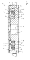
- einen Querschnitt durch das Kombifräswerkzeug
- Figur 3
- eine Draufsicht auf eine Oberseite des Kombifräswerkzeuges
- Ein Kombifräswerkzeug 1 zur Vorbereitung von Buchblockrücken für das Auftragen von Klebstoff zum Verbinden der Blätter weist einen rotationsangetriebenen Werkzeugkopf 2 auf. Der Werkzeugkopf 2 weist einen "Egalisierwerkzeuge" tragenden Außenring 3 auf und eine koaxial dazu angeordnete und fest damit verbundene Aufnahme 4 z. B. Flanschverbindung für eine Antriebswelle 6 des Kombifräswerkzeuges 1 auf.
- Zwischen dem Außenring 3 und der Aufnahme 4 ist eine Anzahl von Werkzeuge tragenden Ringen 7, 8, 9 koaxial ineinander angeordnet. Die Werkzeugringe 7, 8, 9 sind gegenüber dem Außenring 3 und auch gegeneinander verdrehbar gelagert. Zwischen den Ringen 3, 7, 8, 9, 4 sind Gewinde 11 bis 13 vorgesehen, die durch ihre Gewindegänge eine Höhenpositionierung der verdrehbaren Ringe 7 bis 9 ermöglichen.
- Der Ring 7 ist mit Fräswerkzeugen ausgestattet, sogenannten "Mikrokerbern".
- Der Ring 8 weist sogenannte "Kerber" Fräswerkzeuge auf und der Ring 9 weist "Bürsten" auf.
- Jeder Ring 7 bis 9 weist zu seiner Arretierung eine Anzahl von am Umfang jedes Ringes 7, 8, 9 verteilt angeordneten Druckschrauben 16, 17, 18 auf, welche mit achsparallel zur Antriebswelle 6 angeordneten Gewindebohrungen 21, 22, 23 in Schraubverbindung stehen. Die Druckschrauben 16 bis 18 sind jeweils derart in ihren jeweiligen Gewindebohrungen 21 bis 23 angeordnet, dass eine Spitze 26, 27, 28 jeder Druckschraube 16 bis 18 an einem Boden 24 des Werkzeugkopfes 2 abgestützt ist.
- Durch diese Maßnahme wird ein Spiel aus dem jeweiligen Gewinde 11 bis 13 herausgedrückt und eine Verdrehung des Werkzeugringes 7 bis 9 vermieden.
- Zur Einstellung eines Werkzeugringes 7; 8; 9 und somit einer Höhenpositionierung des jeweiligen auf den Ringen 7 bis 9 angeordneten Werkzeuges werden zunächst die Druckschrauben 16 bis 18 des jeweiligen Ringes 7; 8; 9 gelöst, daraufhin wird dieser im oder gegen den Uhrzeigersinn gedreht, wodurch sich durch die vorzugsweise verwendeten Linksgewinde eine Hochstellung des Werkzeugringes gegenüber dem als Basis dienenden Außenring 3 dadurch ergibt, dass der jeweilige Ring im Uhrzeigersinn gedreht wird. Eine Verdrehung gegen den Uhrzeigersinn bewirkt entsprechend eine Niederstellung des Ringes. Durch jeweils zwischen den Ringen angeordnete Skalierungen 29, 31, 32 ist ein genaues Maß für die Höher- oder Tieferstellung leicht ablesbar. Nach einer erfolgten Positionierung werden die Druckschrauben 16 bis 18 soweit in ihre Gewindebohrungen 21 bis 23 hinein geschraubt, bis die jeweilige Spitze 26; 27, 28 den Boden 24 des Werkzeugkopfes 2 berührt. Vorzugsweise wird ein einzuhaltendes Drehmoment vorgegeben, damit eine sichere Arretierung gewährleistet ist.
-
- 1
- Kombifräswerkzeug
- 2
- Werkzeugkopf
- 3
- Außenring (Egalisierwerkzeug)
- 4
- Aufnahme (6)
- 5 6
- Antriebswelle
- 7
- Werkzeugring (Mikrokerber)
- 8
- Werkzeugring (Kerber)
- 9
- Werkzeugring (Bürste)
- 10 11
- Gewinde
- 12
- Gewinde
- 13
- Gewinde
- 14
- Gewinde
- 15 16
- Druckschrauben (7)
- 17
- Druckschrauben (8)
- 18
- Druckschrauben (9)
- 20 21
- Gewindebohrung (16)
- 22
- Gewindebohrung (17)
- 23
- Gewindebohrung (18)
- 24
- Boden (2)
- 26
- Spitze (16)
- 27
- Spitze (17)
- 28
- Spitze (18)
- 29
- Skalierung (3 - 7)
- 30 31
- Skalierung (7-8)
- 32
- Skalierung (8 - 9)
Claims (8)
- Kombifräswerkzeug mit einem rotationsangetriebenen Werkzeugkopf mit am Umfang verteilt angeordneten äußeren Werkzeugen und mit koaxial innerhalb von den äußeren Werkzeugen verdrehbar angeordneten weiteren Werkzeugen,
dadurch gekennzeichnet,
dass die weiteren Werkzeuge jeweils auf einem Werkzeugring (7; 8; 9) angeordnet sind,
dass die Werkzeugringe (7, 8, 9) mittels vorgesehener Gewinde (11, 12, 13) miteinander in Schraubverbindung stehen und
das jeder Werkzeugring (7 bis 9) in beliebiger Position mittels einer Anzahl von Druckschrauben (16; 17; 18) an einem Boden (24) des Werkzeugkopfes (2) stufenlos arretierbar ist. - Kombifräswerkzeug nach Anspruch 1,
dadurch gekennzeichnet,
dass die Schraubverbindungen als Linksgewinde (11 bis 14) ausgebildet sind. - Kombifräswerkzeug nach Anspruch 1,
dadurch gekennzeichnet,
dass Skalierungen (26, 27, 28) zwischen den benachbarten Werkzeugringen (3, 7, 8, 9) vorgesehen sind. - Kombifräswerkzeug nach einem der Ansprüche 1 bis 3,
dadurch gekennzeichnet,
dass der Werkzeugkopf (2) eine Aufnahme (4) für eine Antriebswelle (6) aufweist. - Kombifräswerkzeug nach einem der Ansprüche 1 bis 4,
dadurch gekennzeichnet,
dass der erste Werkzeugring (7) Fräswerkzeuge des Typs "Mikrokerber" trägt. - Kombifräswerkzeug nach einem der Ansprüche 1 bis 4,
dadurch gekennzeichnet,
dass der zweite Werkzeugring (8) Fräswerkzeuge des Typs "Kerber" trägt. - Kombifräswerkzeug nach einem der Ansprüche 1 bis 4,
dadurch gekennzeichnet,
dass der dritte Werkzeugring (9) Bürsten trägt. - Kombifräswerkzeug nach einem der Ansprüche 1 bis 4,
dadurch gekennzeichnet,
dass der Werkzeugkopf (2) auf seinem Außenring (3) "Egalisierwerkzeuge" trägt.
Applications Claiming Priority (1)
| Application Number | Priority Date | Filing Date | Title |
|---|---|---|---|
| DE102011105033A DE102011105033A1 (de) | 2011-06-20 | 2011-06-20 | Vorrichtung zur Rückenbearbeitung von Buchblocks |
Publications (3)
| Publication Number | Publication Date |
|---|---|
| EP2537614A2 true EP2537614A2 (de) | 2012-12-26 |
| EP2537614A3 EP2537614A3 (de) | 2013-07-24 |
| EP2537614B1 EP2537614B1 (de) | 2014-12-03 |
Family
ID=46168257
Family Applications (1)
| Application Number | Title | Priority Date | Filing Date |
|---|---|---|---|
| EP12169294.1A Active EP2537614B1 (de) | 2011-06-20 | 2012-05-24 | Vorrichtung zur Rückenbearbeitung von Buchblocks |
Country Status (4)
| Country | Link |
|---|---|
| EP (1) | EP2537614B1 (de) |
| JP (1) | JP5892874B2 (de) |
| CN (1) | CN102837526B (de) |
| DE (1) | DE102011105033A1 (de) |
Cited By (1)
| Publication number | Priority date | Publication date | Assignee | Title |
|---|---|---|---|---|
| IT202300009096A1 (it) * | 2023-05-08 | 2024-11-08 | K G S S R L Unipersonale | Dispositivo grecatore per macchine brossuratrici |
Families Citing this family (2)
| Publication number | Priority date | Publication date | Assignee | Title |
|---|---|---|---|---|
| ITUA20161988A1 (it) * | 2016-03-24 | 2017-09-24 | K G S S R L Unipersonale | Utensile rotativo multifunzionale per macchine brossuratrici |
| CN107442829B (zh) * | 2016-10-20 | 2020-03-31 | 江苏财经职业技术学院 | 一种可调精铣切深的组合式面铣刀 |
Citations (1)
| Publication number | Priority date | Publication date | Assignee | Title |
|---|---|---|---|---|
| DE10022836B4 (de) | 2000-05-10 | 2008-07-10 | Kolbus Gmbh & Co. Kg | Vorrichtung zur Rückenbearbeitung von Buchblocks |
Family Cites Families (5)
| Publication number | Priority date | Publication date | Assignee | Title |
|---|---|---|---|---|
| JPS5866611A (ja) * | 1981-10-12 | 1983-04-20 | Toshiba Mach Co Ltd | 正面フライスカツタ |
| JPS6031914U (ja) * | 1983-08-08 | 1985-03-04 | 三菱重工業株式会社 | ミリングマシン用カツタ |
| EP0538198B1 (de) * | 1991-10-18 | 1996-12-27 | Grapha-Holding Ag | Rotierend angetriebener Fräskopf |
| DE10230054A1 (de) * | 2002-07-04 | 2004-01-22 | Heidelberger Druckmaschinen Ag | Vorrichtung zum Bearbeiten von Seitenkanten von blattförmigen Bedruckstoffen |
| JP4326543B2 (ja) * | 2006-04-27 | 2009-09-09 | ホリゾン・インターナショナル株式会社 | 無線綴製本処理装置 |
-
2011
- 2011-06-20 DE DE102011105033A patent/DE102011105033A1/de not_active Withdrawn
-
2012
- 2012-05-24 EP EP12169294.1A patent/EP2537614B1/de active Active
- 2012-06-19 JP JP2012137809A patent/JP5892874B2/ja active Active
- 2012-06-20 CN CN201210210741.3A patent/CN102837526B/zh active Active
Patent Citations (1)
| Publication number | Priority date | Publication date | Assignee | Title |
|---|---|---|---|---|
| DE10022836B4 (de) | 2000-05-10 | 2008-07-10 | Kolbus Gmbh & Co. Kg | Vorrichtung zur Rückenbearbeitung von Buchblocks |
Cited By (2)
| Publication number | Priority date | Publication date | Assignee | Title |
|---|---|---|---|---|
| IT202300009096A1 (it) * | 2023-05-08 | 2024-11-08 | K G S S R L Unipersonale | Dispositivo grecatore per macchine brossuratrici |
| EP4461552A1 (de) * | 2023-05-08 | 2024-11-13 | K.G.S. Srl Unipersonale | Einkerbvorrichtung für buchbindemaschinen |
Also Published As
| Publication number | Publication date |
|---|---|
| DE102011105033A1 (de) | 2012-12-20 |
| JP2013000881A (ja) | 2013-01-07 |
| EP2537614B1 (de) | 2014-12-03 |
| EP2537614A3 (de) | 2013-07-24 |
| JP5892874B2 (ja) | 2016-03-23 |
| CN102837526B (zh) | 2016-02-03 |
| CN102837526A (zh) | 2012-12-26 |
Similar Documents
| Publication | Publication Date | Title |
|---|---|---|
| DE102008022844A1 (de) | Werkzeug zum Dreh-Dreh-Räumen oder Außenfräsen von Werkstücken | |
| EP2029305A2 (de) | Maschinenwerkzeug sowie schneidring für ein maschinenwerkzeug | |
| DE102012022612B4 (de) | Schneidwerkzeug mit Taschenausformung zur Spannungsreduzierung | |
| DE102010010589B4 (de) | Dental- oder chirurgisches Werkzeug | |
| DE102009044855A1 (de) | Bausatz zum Nachrüsten einer Elektrodenschleifvorrichtung und Elektrodenschleifvorrichtung | |
| DE102008045674A1 (de) | Maschinenwerkzeug mit verstellbarer Schneidplatte | |
| EP2537614B1 (de) | Vorrichtung zur Rückenbearbeitung von Buchblocks | |
| EP1889700B1 (de) | Multifunktionsaggregat | |
| DE112012002653T5 (de) | Winkelförmiger Einsatz zum Bohren und Eintauchen | |
| WO2014131403A2 (de) | Schneidscheibe und trägerkörper eines schneidrads zur bildung einer fase | |
| DE102014008033B4 (de) | Fräswerkzeug | |
| WO2018234193A1 (de) | Arbeitsspindel mit radialklemmeinrichtung | |
| DE102008037578A1 (de) | Vorrichtung und Verzahnen von Werkrädern mit einem konischen Wälzfräser | |
| DE102007038935A1 (de) | Stabmesserkopf und entsprechende Werkzeugmaschine | |
| DE102015109099B4 (de) | Durch Stirnseitenmitnehmen zu bearbeitendes Material und Verfahren zu dessen Bearbeitung | |
| DE102009044857A1 (de) | Anordnung zum Schleifen von Elektroden und Schleifscheibe | |
| DE202015103583U1 (de) | Werkzeughalter zur lösbaren Befestigung wenigstens eines Schneideinsatzes | |
| DE102018132287A1 (de) | System zum Einstellen der Länge eines Werkzeugs | |
| EP1782917A1 (de) | Aufnahme für ein Schleifwerkzeug, Schleifwerkzeug und Tragkörper für ein Schleifwerkzeug | |
| WO2006131289A1 (de) | Verfahren zum einbringen einer verriegelungsnut in eine nutflanke | |
| DE202004003080U1 (de) | Fräswerkzeug | |
| DE10022836B4 (de) | Vorrichtung zur Rückenbearbeitung von Buchblocks | |
| DE10250018A1 (de) | Maschinenwerkzeug mit verstellbarer Schneide | |
| DE202014011134U1 (de) | Fräswerkzeug | |
| DE102006047343B3 (de) | Schleifmaschine |
Legal Events
| Date | Code | Title | Description |
|---|---|---|---|
| PUAI | Public reference made under article 153(3) epc to a published international application that has entered the european phase |
Free format text: ORIGINAL CODE: 0009012 |
|
| AK | Designated contracting states |
Kind code of ref document: A2 Designated state(s): AL AT BE BG CH CY CZ DE DK EE ES FI FR GB GR HR HU IE IS IT LI LT LU LV MC MK MT NL NO PL PT RO RS SE SI SK SM TR |
|
| AX | Request for extension of the european patent |
Extension state: BA ME |
|
| PUAL | Search report despatched |
Free format text: ORIGINAL CODE: 0009013 |
|
| AK | Designated contracting states |
Kind code of ref document: A3 Designated state(s): AL AT BE BG CH CY CZ DE DK EE ES FI FR GB GR HR HU IE IS IT LI LT LU LV MC MK MT NL NO PL PT RO RS SE SI SK SM TR |
|
| AX | Request for extension of the european patent |
Extension state: BA ME |
|
| RIC1 | Information provided on ipc code assigned before grant |
Ipc: B23C 5/24 20060101AFI20130617BHEP Ipc: B42C 5/04 20060101ALI20130617BHEP |
|
| 17P | Request for examination filed |
Effective date: 20140124 |
|
| RBV | Designated contracting states (corrected) |
Designated state(s): AL AT BE BG CH CY CZ DE DK EE ES FI FR GB GR HR HU IE IS IT LI LT LU LV MC MK MT NL NO PL PT RO RS SE SI SK SM TR |
|
| GRAP | Despatch of communication of intention to grant a patent |
Free format text: ORIGINAL CODE: EPIDOSNIGR1 |
|
| INTG | Intention to grant announced |
Effective date: 20140701 |
|
| GRAS | Grant fee paid |
Free format text: ORIGINAL CODE: EPIDOSNIGR3 |
|
| GRAA | (expected) grant |
Free format text: ORIGINAL CODE: 0009210 |
|
| RAP1 | Party data changed (applicant data changed or rights of an application transferred) |
Owner name: MUELLER MARTINI HOLDING AG |
|
| AK | Designated contracting states |
Kind code of ref document: B1 Designated state(s): AL AT BE BG CH CY CZ DE DK EE ES FI FR GB GR HR HU IE IS IT LI LT LU LV MC MK MT NL NO PL PT RO RS SE SI SK SM TR |
|
| REG | Reference to a national code |
Ref country code: GB Ref legal event code: FG4D Free format text: NOT ENGLISH |
|
| REG | Reference to a national code |
Ref country code: CH Ref legal event code: EP Ref country code: AT Ref legal event code: REF Ref document number: 699064 Country of ref document: AT Kind code of ref document: T Effective date: 20141215 |
|
| REG | Reference to a national code |
Ref country code: IE Ref legal event code: FG4D Free format text: LANGUAGE OF EP DOCUMENT: GERMAN |
|
| REG | Reference to a national code |
Ref country code: DE Ref legal event code: R096 Ref document number: 502012001713 Country of ref document: DE Effective date: 20150115 |
|
| REG | Reference to a national code |
Ref country code: NL Ref legal event code: VDEP Effective date: 20141203 |
|
| PG25 | Lapsed in a contracting state [announced via postgrant information from national office to epo] |
Ref country code: LT Free format text: LAPSE BECAUSE OF FAILURE TO SUBMIT A TRANSLATION OF THE DESCRIPTION OR TO PAY THE FEE WITHIN THE PRESCRIBED TIME-LIMIT Effective date: 20141203 Ref country code: NO Free format text: LAPSE BECAUSE OF FAILURE TO SUBMIT A TRANSLATION OF THE DESCRIPTION OR TO PAY THE FEE WITHIN THE PRESCRIBED TIME-LIMIT Effective date: 20150303 Ref country code: ES Free format text: LAPSE BECAUSE OF FAILURE TO SUBMIT A TRANSLATION OF THE DESCRIPTION OR TO PAY THE FEE WITHIN THE PRESCRIBED TIME-LIMIT Effective date: 20141203 Ref country code: FI Free format text: LAPSE BECAUSE OF FAILURE TO SUBMIT A TRANSLATION OF THE DESCRIPTION OR TO PAY THE FEE WITHIN THE PRESCRIBED TIME-LIMIT Effective date: 20141203 Ref country code: NL Free format text: LAPSE BECAUSE OF FAILURE TO SUBMIT A TRANSLATION OF THE DESCRIPTION OR TO PAY THE FEE WITHIN THE PRESCRIBED TIME-LIMIT Effective date: 20141203 |
|
| REG | Reference to a national code |
Ref country code: LT Ref legal event code: MG4D |
|
| PG25 | Lapsed in a contracting state [announced via postgrant information from national office to epo] |
Ref country code: CY Free format text: LAPSE BECAUSE OF FAILURE TO SUBMIT A TRANSLATION OF THE DESCRIPTION OR TO PAY THE FEE WITHIN THE PRESCRIBED TIME-LIMIT Effective date: 20141203 Ref country code: RS Free format text: LAPSE BECAUSE OF FAILURE TO SUBMIT A TRANSLATION OF THE DESCRIPTION OR TO PAY THE FEE WITHIN THE PRESCRIBED TIME-LIMIT Effective date: 20141203 Ref country code: SE Free format text: LAPSE BECAUSE OF FAILURE TO SUBMIT A TRANSLATION OF THE DESCRIPTION OR TO PAY THE FEE WITHIN THE PRESCRIBED TIME-LIMIT Effective date: 20141203 Ref country code: GR Free format text: LAPSE BECAUSE OF FAILURE TO SUBMIT A TRANSLATION OF THE DESCRIPTION OR TO PAY THE FEE WITHIN THE PRESCRIBED TIME-LIMIT Effective date: 20150304 Ref country code: LV Free format text: LAPSE BECAUSE OF FAILURE TO SUBMIT A TRANSLATION OF THE DESCRIPTION OR TO PAY THE FEE WITHIN THE PRESCRIBED TIME-LIMIT Effective date: 20141203 Ref country code: HR Free format text: LAPSE BECAUSE OF FAILURE TO SUBMIT A TRANSLATION OF THE DESCRIPTION OR TO PAY THE FEE WITHIN THE PRESCRIBED TIME-LIMIT Effective date: 20141203 |
|
| PG25 | Lapsed in a contracting state [announced via postgrant information from national office to epo] |
Ref country code: RO Free format text: LAPSE BECAUSE OF FAILURE TO SUBMIT A TRANSLATION OF THE DESCRIPTION OR TO PAY THE FEE WITHIN THE PRESCRIBED TIME-LIMIT Effective date: 20141203 Ref country code: EE Free format text: LAPSE BECAUSE OF FAILURE TO SUBMIT A TRANSLATION OF THE DESCRIPTION OR TO PAY THE FEE WITHIN THE PRESCRIBED TIME-LIMIT Effective date: 20141203 Ref country code: CZ Free format text: LAPSE BECAUSE OF FAILURE TO SUBMIT A TRANSLATION OF THE DESCRIPTION OR TO PAY THE FEE WITHIN THE PRESCRIBED TIME-LIMIT Effective date: 20141203 Ref country code: SK Free format text: LAPSE BECAUSE OF FAILURE TO SUBMIT A TRANSLATION OF THE DESCRIPTION OR TO PAY THE FEE WITHIN THE PRESCRIBED TIME-LIMIT Effective date: 20141203 Ref country code: PT Free format text: LAPSE BECAUSE OF FAILURE TO SUBMIT A TRANSLATION OF THE DESCRIPTION OR TO PAY THE FEE WITHIN THE PRESCRIBED TIME-LIMIT Effective date: 20150403 |
|
| PG25 | Lapsed in a contracting state [announced via postgrant information from national office to epo] |
Ref country code: PL Free format text: LAPSE BECAUSE OF FAILURE TO SUBMIT A TRANSLATION OF THE DESCRIPTION OR TO PAY THE FEE WITHIN THE PRESCRIBED TIME-LIMIT Effective date: 20141203 Ref country code: IS Free format text: LAPSE BECAUSE OF FAILURE TO SUBMIT A TRANSLATION OF THE DESCRIPTION OR TO PAY THE FEE WITHIN THE PRESCRIBED TIME-LIMIT Effective date: 20150403 |
|
| REG | Reference to a national code |
Ref country code: DE Ref legal event code: R097 Ref document number: 502012001713 Country of ref document: DE |
|
| PLBE | No opposition filed within time limit |
Free format text: ORIGINAL CODE: 0009261 |
|
| STAA | Information on the status of an ep patent application or granted ep patent |
Free format text: STATUS: NO OPPOSITION FILED WITHIN TIME LIMIT |
|
| PG25 | Lapsed in a contracting state [announced via postgrant information from national office to epo] |
Ref country code: DK Free format text: LAPSE BECAUSE OF FAILURE TO SUBMIT A TRANSLATION OF THE DESCRIPTION OR TO PAY THE FEE WITHIN THE PRESCRIBED TIME-LIMIT Effective date: 20141203 |
|
| 26N | No opposition filed |
Effective date: 20150904 |
|
| PG25 | Lapsed in a contracting state [announced via postgrant information from national office to epo] |
Ref country code: LU Free format text: LAPSE BECAUSE OF FAILURE TO SUBMIT A TRANSLATION OF THE DESCRIPTION OR TO PAY THE FEE WITHIN THE PRESCRIBED TIME-LIMIT Effective date: 20150524 Ref country code: MC Free format text: LAPSE BECAUSE OF FAILURE TO SUBMIT A TRANSLATION OF THE DESCRIPTION OR TO PAY THE FEE WITHIN THE PRESCRIBED TIME-LIMIT Effective date: 20141203 |
|
| REG | Reference to a national code |
Ref country code: IE Ref legal event code: MM4A |
|
| REG | Reference to a national code |
Ref country code: FR Ref legal event code: ST Effective date: 20160129 |
|
| PG25 | Lapsed in a contracting state [announced via postgrant information from national office to epo] |
Ref country code: SI Free format text: LAPSE BECAUSE OF FAILURE TO SUBMIT A TRANSLATION OF THE DESCRIPTION OR TO PAY THE FEE WITHIN THE PRESCRIBED TIME-LIMIT Effective date: 20141203 |
|
| PG25 | Lapsed in a contracting state [announced via postgrant information from national office to epo] |
Ref country code: IE Free format text: LAPSE BECAUSE OF NON-PAYMENT OF DUE FEES Effective date: 20150524 |
|
| PG25 | Lapsed in a contracting state [announced via postgrant information from national office to epo] |
Ref country code: FR Free format text: LAPSE BECAUSE OF NON-PAYMENT OF DUE FEES Effective date: 20150601 |
|
| PG25 | Lapsed in a contracting state [announced via postgrant information from national office to epo] |
Ref country code: MT Free format text: LAPSE BECAUSE OF FAILURE TO SUBMIT A TRANSLATION OF THE DESCRIPTION OR TO PAY THE FEE WITHIN THE PRESCRIBED TIME-LIMIT Effective date: 20141203 |
|
| GBPC | Gb: european patent ceased through non-payment of renewal fee |
Effective date: 20160524 |
|
| PG25 | Lapsed in a contracting state [announced via postgrant information from national office to epo] |
Ref country code: BG Free format text: LAPSE BECAUSE OF FAILURE TO SUBMIT A TRANSLATION OF THE DESCRIPTION OR TO PAY THE FEE WITHIN THE PRESCRIBED TIME-LIMIT Effective date: 20141203 Ref country code: SM Free format text: LAPSE BECAUSE OF FAILURE TO SUBMIT A TRANSLATION OF THE DESCRIPTION OR TO PAY THE FEE WITHIN THE PRESCRIBED TIME-LIMIT Effective date: 20141203 Ref country code: HU Free format text: LAPSE BECAUSE OF FAILURE TO SUBMIT A TRANSLATION OF THE DESCRIPTION OR TO PAY THE FEE WITHIN THE PRESCRIBED TIME-LIMIT; INVALID AB INITIO Effective date: 20120524 Ref country code: GB Free format text: LAPSE BECAUSE OF NON-PAYMENT OF DUE FEES Effective date: 20160524 |
|
| PG25 | Lapsed in a contracting state [announced via postgrant information from national office to epo] |
Ref country code: BE Free format text: LAPSE BECAUSE OF NON-PAYMENT OF DUE FEES Effective date: 20150531 |
|
| PG25 | Lapsed in a contracting state [announced via postgrant information from national office to epo] |
Ref country code: TR Free format text: LAPSE BECAUSE OF FAILURE TO SUBMIT A TRANSLATION OF THE DESCRIPTION OR TO PAY THE FEE WITHIN THE PRESCRIBED TIME-LIMIT Effective date: 20141203 |
|
| PG25 | Lapsed in a contracting state [announced via postgrant information from national office to epo] |
Ref country code: MK Free format text: LAPSE BECAUSE OF FAILURE TO SUBMIT A TRANSLATION OF THE DESCRIPTION OR TO PAY THE FEE WITHIN THE PRESCRIBED TIME-LIMIT Effective date: 20141203 |
|
| REG | Reference to a national code |
Ref country code: AT Ref legal event code: MM01 Ref document number: 699064 Country of ref document: AT Kind code of ref document: T Effective date: 20170524 |
|
| PG25 | Lapsed in a contracting state [announced via postgrant information from national office to epo] |
Ref country code: AT Free format text: LAPSE BECAUSE OF NON-PAYMENT OF DUE FEES Effective date: 20170524 |
|
| PG25 | Lapsed in a contracting state [announced via postgrant information from national office to epo] |
Ref country code: AL Free format text: LAPSE BECAUSE OF FAILURE TO SUBMIT A TRANSLATION OF THE DESCRIPTION OR TO PAY THE FEE WITHIN THE PRESCRIBED TIME-LIMIT Effective date: 20141203 |
|
| PGFP | Annual fee paid to national office [announced via postgrant information from national office to epo] |
Ref country code: CH Payment date: 20190823 Year of fee payment: 8 |
|
| PG25 | Lapsed in a contracting state [announced via postgrant information from national office to epo] |
Ref country code: CH Free format text: LAPSE BECAUSE OF NON-PAYMENT OF DUE FEES Effective date: 20200531 Ref country code: LI Free format text: LAPSE BECAUSE OF NON-PAYMENT OF DUE FEES Effective date: 20200531 |
|
| PGFP | Annual fee paid to national office [announced via postgrant information from national office to epo] |
Ref country code: DE Payment date: 20250602 Year of fee payment: 14 |
|
| PGFP | Annual fee paid to national office [announced via postgrant information from national office to epo] |
Ref country code: IT Payment date: 20250529 Year of fee payment: 14 |