EP2536640B1 - Stackable bottle with handle - Google Patents
Stackable bottle with handle Download PDFInfo
- Publication number
- EP2536640B1 EP2536640B1 EP11711659.0A EP11711659A EP2536640B1 EP 2536640 B1 EP2536640 B1 EP 2536640B1 EP 11711659 A EP11711659 A EP 11711659A EP 2536640 B1 EP2536640 B1 EP 2536640B1
- Authority
- EP
- European Patent Office
- Prior art keywords
- bottle
- top piece
- handle
- set according
- litres
- Prior art date
- Legal status (The legal status is an assumption and is not a legal conclusion. Google has not performed a legal analysis and makes no representation as to the accuracy of the status listed.)
- Not-in-force
Links
- 230000002093 peripheral effect Effects 0.000 claims description 20
- 239000000463 material Substances 0.000 claims description 8
- 238000000071 blow moulding Methods 0.000 claims description 7
- 229920000139 polyethylene terephthalate Polymers 0.000 claims description 3
- 239000005020 polyethylene terephthalate Substances 0.000 claims description 3
- 238000001746 injection moulding Methods 0.000 claims description 2
- 239000004033 plastic Substances 0.000 claims description 2
- 229920003023 plastic Polymers 0.000 claims description 2
- -1 polyethylene terephthalate Polymers 0.000 claims description 2
- 230000000694 effects Effects 0.000 description 3
- 239000000126 substance Substances 0.000 description 3
- 230000006978 adaptation Effects 0.000 description 2
- 230000000295 complement effect Effects 0.000 description 2
- 239000012530 fluid Substances 0.000 description 2
- 238000004519 manufacturing process Methods 0.000 description 2
- 230000001154 acute effect Effects 0.000 description 1
- 238000004140 cleaning Methods 0.000 description 1
- 238000009826 distribution Methods 0.000 description 1
- 230000005484 gravity Effects 0.000 description 1
- 239000004626 polylactic acid Substances 0.000 description 1
- 230000008092 positive effect Effects 0.000 description 1
- 239000000243 solution Substances 0.000 description 1
Images


Classifications
-
- B—PERFORMING OPERATIONS; TRANSPORTING
- B65—CONVEYING; PACKING; STORING; HANDLING THIN OR FILAMENTARY MATERIAL
- B65D—CONTAINERS FOR STORAGE OR TRANSPORT OF ARTICLES OR MATERIALS, e.g. BAGS, BARRELS, BOTTLES, BOXES, CANS, CARTONS, CRATES, DRUMS, JARS, TANKS, HOPPERS, FORWARDING CONTAINERS; ACCESSORIES, CLOSURES, OR FITTINGS THEREFOR; PACKAGING ELEMENTS; PACKAGES
- B65D23/00—Details of bottles or jars not otherwise provided for
- B65D23/10—Handles
- B65D23/104—Handles formed separately
-
- B—PERFORMING OPERATIONS; TRANSPORTING
- B65—CONVEYING; PACKING; STORING; HANDLING THIN OR FILAMENTARY MATERIAL
- B65D—CONTAINERS FOR STORAGE OR TRANSPORT OF ARTICLES OR MATERIALS, e.g. BAGS, BARRELS, BOTTLES, BOXES, CANS, CARTONS, CRATES, DRUMS, JARS, TANKS, HOPPERS, FORWARDING CONTAINERS; ACCESSORIES, CLOSURES, OR FITTINGS THEREFOR; PACKAGING ELEMENTS; PACKAGES
- B65D21/00—Nestable, stackable or joinable containers; Containers of variable capacity
- B65D21/02—Containers specially shaped, or provided with fittings or attachments, to facilitate nesting, stacking, or joining together
- B65D21/0209—Containers specially shaped, or provided with fittings or attachments, to facilitate nesting, stacking, or joining together stackable or joined together one-upon-the-other in the upright or upside-down position
- B65D21/0224—Auxiliary removable stacking elements other than covers
Definitions
- the invention relates to a set comprising at least one first and one second stackable bottle, wherein each bottle is made of a material such that the bottle can be formed by blow-moulding, and wherein each bottle has a top piece which is mounted around the bottle neck and extends to a peripheral part of the bottle, wherein the top piece is dimensioned such that in a stacked position of the first and second bottle, the top piece of the first bottle lies against a peripheral base part of the second bottle, wherein a handle is connected with said top piece within said peripheral part of the bottle and at a distance from this peripheral part of the bottle, said top piece comprising an annular element with fixing means on an inside of said annular element such that the top piece is able, from a bottle opening, to be pushed with the annular element over the bottle neck in order to attach the top piece to the bottle, and is able to offer resistance to movement in the opposite direction.
- the invention furthermore relates to a stackable bottle from this set. Throughout the entire patent specification a bottle or a stackable
- Such bottles are known from WO2009/095109 , which is regarded as the closest prior art.
- This document describes a stackable bottle with a top piece. This document describes how the top piece facilitates the handling and stacking of the bottle.
- One disadvantage of the known bottle is that on lifting a full bottle, a deformation of the top piece occurs.
- the object of the invention is to obtain a bottle wherein the bottle is easier to handle.
- a bottle according to the invention is characterised in that the handle is connected directly to said annular element. Because the handle is connected with the top piece, the bottle can easily be lifted via this handle and also be handled by this on a non-flat floor. By connecting this handle to the base part within the peripheral part and at a distance from this peripheral part, the handle has no disadvantageous effect on the rollable nature of the bottle. Also the bottle remains stackable, namely the handle does not protrude at any point because it is placed within the peripheral part of the bottle. Thus a bottle is obtained which is both stackable and easy to handle.
- the handle is attached to the top piece as close as possible to the bottle neck, namely the annular element comprises fixing means on the inside and is attached to the bottle neck by these.
- the distance between firstly the fixing point of the handle to the top piece and secondly the fixing point of the top piece to the bottle is as small as possible. This avoids that, on lifting the bottle via the handle, great moment forces occur in the top piece. If namely the handle were attached to the peripheral part of the top piece, on lifting a moment force would occur in the bottle neck which would have to be absorbed by the top piece.
- the top piece need only absorb forces which occur from stacking, namely downwardly directed pressure. No moment forces need be absorbed by the top piece, whereby the top piece need not be dimensioned extra strong.
- the top piece is attached to said bottle neck by clipping.
- Assembly of two parts by clipping them together is simple to automate.
- a bottle and top piece are obtained which can be assembled in a simple manner by an assembly machine.
- clipping does not require the bottle and top piece to be rotatable in relation to each other.
- a top piece can easily be fitted with a top piece.
- a bottle largely rectangular in cross-section can easily be fitted with a correspondingly rectangular top piece by clipping.
- top piece and said handle are made of one piece of plastic by injection moulding.
- top piece and handle are made of one piece of plastic by injection moulding.
- injection moulding By making the top piece and handle of one piece, no assembly step is required to attach the top piece and handle together.
- injection-moulded parts can have widely varying shapes and material properties. Further advantages are the low cost price and simplicity of mass production.
- said handle extends in a plane which lies substantially perpendicular in relation to a longitudinal axis of the bottle.
- the handle extends inside the top piece, which consequently facilitates stacking.
- a handle which does not extend inside the top piece therefore protrudes outside this top piece, which makes stacking the bottle more difficult.
- the handle protrudes perpendicular to the longitudinal axis of the bottle only if no external force is applied to the handle. When an external force is applied, for example when lifting the bottle via the handle, due to internal stresses the handle can deform and thus extend in another direction, for example upward.
- said top piece extends toward said peripheral part of the bottle, at least partly making contact with a shoulder part of the bottle. Because the top piece lies in contact with the shoulder part of the bottle, the force exerted on the top piece can be transferred to this shoulder part of the bottle.
- a bottle lying on the top by its own weight exerts a downward force on the bottle lying below. This downward force is applied to the top piece, namely the bottle on top stands on this, and the top piece transfers this force to the bottle. By bringing the top piece into contact with the shoulder part of the bottle, such downward forces can easily be transferred through the stack.
- Said top piece comprises an annular element with fixing means on the inside of the annular element such that the top piece is able, from a bottle opening, to be pushed with the annular element over the bottle neck in order to attach the top piece to the bottle, and is able to offer resistance to movement in the opposite direction.
- Such a fixing of the top piece to the bottle is very simple and hence cheap. Furthermore pushing a ring form with fixing means over the bottle neck is very easy to automate, which is an advantage in the production process of such bottles with top piece.
- said handle comprises two legs and a gripper part, wherein the two legs are connected each with a first end to the respective end of the gripper part and each with a second end to said annular element.
- the handle can be attached with the annular element on both sides.
- the gripping point of the bottle, on lifting lies closer to the centre of gravity of the bottle, which in symmetrical bottles lies on the longitudinal centre axis. This simplifies lifting and leads to an even distribution of force in the annular element.
- said legs are connected to said annular element such that a first distance, measured between the longitudinal axis of the bottle and the point lying furthest away from this longitudinal axis on said gripper part, is smaller than a second distance measured between said second end of a leg and said point lying furthest away from the longitudinal axis on said gripper part.
- a first distance measured between the longitudinal axis of the bottle and the point lying furthest away from this longitudinal axis on said gripper part
- a second distance measured between said second end of a leg and said point lying furthest away from the longitudinal axis on said gripper part On lifting of the bottle, an upward force is applied to the gripper part.
- the legs of the handle, the gripper part of which lies eccentric in relation to the longitudinal axis of the bottle bend up in the direction of the longitudinal axis.
- the gripper part in particular the part of the gripper where the fingers are located during lifting, comes closer to the bottle neck and the bottle cap.
- each of the legs at their ends extends into a ring part which brings the legs towards each other and has a diameter largely equal to the outer diameter of the annular element, and in that both legs are attached to the annular element by one end of this ring part.
- the distance increases between firstly the fixing points of the legs with the annular element and secondly the part of the gripper part where the fingers hook behind, whereby the radius over which the legs can bend under load is also increased. This increase in distance keeps the gripper part away from the bottle neck and bottle cap on lifting of the bottle, preferably even causes it to bend over the bottle cap.
- a bottle according to the invention has a capacity of greater than 5 litres, preferably greater than 10 litres, more preferably greater than 15 litres, and a capacity of less than 35 litres, preferably less than 30 litres, more preferably less than 25 litres. Bottles with such capacity have external dimensions which make handling without handle difficult.
- Figure 2 shows a bottle 1 which is produced linearly symmetrical about a longitudinal axis 2.
- the bottle viewed from top to bottom along longitudinal axis 2, comprises an optional bottle top 3 (shown in figures 5 and 6 ), a bottle neck 4, a shoulder part 5, a body part 6 and a base part 7.
- the bottle 1 is produced by means of blow moulding from a material which can be blow moulded, preferably polyethylene terephthalate (PET).
- PET polyethylene terephthalate
- An alternative material which allows the bottle 1 to be produced by means of blow moulding is polylactic acid (PLA).
- the bottle 1 according to the invention furthermore comprises a top piece 12 attached to the bottle neck 4.
- the bottle cap 3 is preferably attached to the bottle neck 4 by means of a screw connection, wherein the bottle cap 3 and bottle neck 4 have corresponding screw threads.
- other systems such as clip systems can also be used to attach the bottle cap 3 to the neck.
- the bottle neck 4 furthermore preferably comprises a collar 8 which makes it possible to grip the bottle 1 in a simple manner, in particular during blow moulding of the bottle 1.
- the shoulder part 5 of the bottle 1 joins the bottle neck 4 to the body part 6 of the bottle 1.
- the shoulder part 5 extends mainly in a radial direction and downward out from the bottle neck 4 which has a first diameter, to transform into the body part 6 of the bottle 1 which has a larger diameter than said first diameter.
- the base part 7 of the bottle 1 closes the body part 6 at the underside so that the bottle 1 is suitable for containing a fluid.
- the underside of the bottle is largely flat. Due to the largely flat underside, the bottle can be placed directly on its underside on a floor without using aids. Furthermore for blow moulding a flat underside, in contrast to an underside with a recess, less material is required. As a result the bottle, in comparison with a bottle with a recessed underside, is lighter and cheaper.
- the underside of the bottle is convex (not shown) and the bottle furthermore contains a bottom piece (not shown) which is attached to the underside of the bottle to make the bottle with a convex underside stackable.
- a bottom piece (not shown) which is attached to the underside of the bottle to make the bottle with a convex underside stackable.
- the bottom piece must however be produced, which entails an additional cost, but this bottom piece can be re-used for the next stackable bottle without intensive cleaning treatment.
- the bottom piece has a form which is complementary to the form of the top piece 12, which makes such bottles stackable.
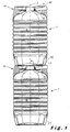
- Figure 1 shows a set of a first bottle and a second bottle in a stacked position in cross section.
- Figure 1 shows how the bottle neck 4 and bottle cap 3 (shown in figures 5 and 6 ) extend centrally and higher than the shoulder part 5 of the bottle 1 .
- the underside of the bottle is largely flat.
- a top piece 12 is provided. Without a top piece, the bottle neck 4 and bottle cap 3 of the bottom bottle would prevent a top bottle with a largely flat underside 7 from being placed stably on the bottom bottle.
- the top piece 12 is attached on at least the bottom bottle and provides this bottle with a raised shoulder part 30.
- the bottle neck and bottle cap do not protrude upward or at least protrude less.
- a bottle 1 with a largely flat underside 7 can be supported on this raised shoulder part 30 without the bottle neck 4 and bottle cap 3 preventing this.
- the dimensions of the top piece 12 are such that the bottle neck 4 and bottle cap 3 of the bottle in the stacked position are bridged in the height direction, with the result that the top bottle can be placed stably on the top piece of the bottom bottle.
- Figures 3 and 4 show a top piece 12 with handle 31 of the bottle 1 according to the invention.
- the top piece 12 is attached to the bottle neck 4.
- the top piece preferably has annular fixing means 15 which are preferably provided centrally in the top piece 12 and on an inside thereof are fitted with counter-hook means 16.
- the annular fixing means 15 with counter-hook means 16 allow the top piece 12 to be pushed over the bottle neck 4 in the direction of the shoulder part 5 while preventing the top piece 12 from being able to move over the bottle neck 4 in a direction away from the shoulder part 5.
- the annular fixing means 15 with counter-hook means 16 and the collar 8 on the bottle neck 4 are complementary in the sense that the counter-hook means 16 can be pushed over the collar 8 in the direction of the shoulder part 5 and prevent an opposite movement back over the collar 8.
- the counter-hook means 16 can comprise hinged lips 16 which, as shown in figure 5 viewed in the mounted position of the top piece 12, form an acute angle ⁇ with the longitudinal axis 2 towards the base part 7 of the bottle 1.
- a handle 31 Within the peripheral edge of the top piece 12 is attached a handle 31.
- the handle 31 does not protrude outside the top piece 12, whereby both the sides and the top side of the bottle 1 with top piece 12 are not influenced by the handle.
- the bottle 1 remains rollable and stackable.
- the handle 31 extends in said top piece 12 in a plane perpendicular to the longitudinal axis 2 of the bottle 1.
- the handle 12 furthermore has a gripper part 17 which at each end is fitted with a leg 18 and 19, so as to form a U-shaped whole of the handle and two legs.
- the two legs 18 and 19 of the U shape have a mutual distance largely equal to the outer diameter of the annular fixing means 15.
- the legs 18 and 19 are both joined to the annular fixing means 15. If the legs 18 and 19 of the U shape are short, little space 20 is left between the gripper part 17 and the annular fixing means 15 to insert the fingers in space 20 and grip the gripper part 17, whereby the handle 12 is difficult to handle.
- the legs 18 and 19 of the U shape are long, a lot of space 20 must be left between the gripper part 17 and the annular fixing means 15 and it will be easy to grip the gripper part 17 with the fingers. However if the legs 18 and 19 are too long, the gripper part 17 will protrude outside the top piece 12. Furthermore space must be provided in the top piece 12 for a handle 31, which requires structural adaptations and whereby the top piece 12 will deviate from an ideal symmetrical form. The longer the legs 18 and 19, the more extensive the structural adaptations.
- the length of the U-shaped legs 18 and 19 of the gripper part 17 is optimally selected in the sense that they are as small as possible yet sufficiently large for fingers to easily be inserted in the space 20 between the gripper part 17 and the annular fixing means 15.
- the distance with reference numeral 20 between the gripper part 17 and the annular fixing means 15 is at least 2.5 cm, more preferably at least 3 cm.
- the distance with reference numeral 20 between the gripper part 17 and the annular fixing means 15 is maximum 4 cm, more preferably maximum 3.5 cm.
- the gripper part 17 and the legs 18 and 19 of the handle 12 can deviate in form from a pure U shape as is the case in figures 3 and 4 .
- the gripper part 17 of the handle 12 is formed as an arc of a circle.
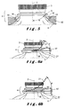
- This problem is illustrated in figure 6 .
- the gripper part 17 which stands eccentric in relation to the longitudinal axis 2 of a bottle 1
- the U- shaped legs 18 and 19 of the gripper part 17 will bend up in the direction of the longitudinal axis 2 as illustrated by dotted line 21 .
- the gripper part 17, or in particular the part of the gripper part 17 in which the fingers are placed for lifting will be closer to the bottle neck 4 and the bottle cap 3.
- This shift of the gripper part 17 can lead to the fingers becoming trapped between the gripper part 17 and the bottle neck 4 or bottle cap 3 in this new position, as illustrated in figure 6a by distance 24.
- This problem can be solved by making the U-shaped legs 18 and 19 longer, whereby the gripper part 17 lies further from the annular fixing means 15 and hence also further from the bottle neck 4 and bottle cap 3, which is disadvantageous as described above.
- this problem can also be solved by allowing the U-shaped legs 18 and 19 at their ends to extend into a ring part 22 ( figure 4 ) which brings the legs 18 and 19 towards each other and has a diameter largely equal to the outer diameter of the annular fixing means 15, and by both legs 18 and 19 being attached at one end of the ring part 22 to the annular fixing means 15.
- the distance is increased between firstly the fixing points of the U-shaped legs 18 and 19 at the annular fixing means 15 and secondly the part of the gripper part 17 where the fingers are hooked, whereby the radius over which the legs 18 and 19 can bend under load is increased. Due to this increase in distance, on lifting the bottle 1 the gripper part 17 will remain further away from the bottle neck 4 and the bottle cap 3, preferably can bend over the bottle cap 3 as shown in figure 6b .
- a handle 12 with circular gripper part 17 in the above solution will have the further positive effect because the legs 8 and 19 of the gripper part 17 will have a springing effect on application of force F.
- the circular gripper part 7 will deform under the force F into an ellipse form whereby the distance between the fixing point of the gripper part 17 and the place where the force F is applied is further enlarged and hence more space is released for the fingers.
- the top piece 12 has ribs 32 (shown in figures 4 and 5 ) which extend from said annular fixing means 15 to a peripheral edge of the top piece.
- this peripheral edge of the top piece when attached to a bottle, lies in the extension of the body of the bottle.
- the ribs 32 are preferably planar, whereby the plane is parallel to the longitudinal axis 2 of the bottle, and extend radially out in relation to this axis 2.
- These planar ribs, at an underside of the top piece preferably have a form such that in the attached position of the top piece, the ribs 32 lie against the shoulder part 5 of the bottle.
- the planar ribs 32 preferably have, on the top of the top piece, a form such that the ribs 32 in stacked position lie against the underside of the top bottle.
- the ribs 32 support and partly form the raised shoulder part 30.
- the top piece with the ribs shows a structure similar to a bicycle wheel, where the outermost edge of the wheel, the peripheral part of the top piece, is joined by means of spokes, the ribs, to the innermost element, the annular fixing means.
- the handle 31 is preferably placed between two successive ribs 43.
- a rib 32 to be provided below the handle 31, where the form of this rib 32 on the top of the top piece deviates from the form of the other ribs.
- the top piece 12 can prevent evacuation by pouring from the stackable bottle according to the invention.
- the bottle according to the invention contains evacuation means, preferably a pump, to evacuate the bottle without this having to be tilted.
- the top piece comprises a pouring spout 33.
- the pouring spout 33 is shaped as a tubular segment which extends between the annular fixing means 15 and the peripheral edge of the top piece 12.
- the pouring spout 33 is provided at the top of the top piece 12, preferably opposite the handle 31.
- a bottle 1 according to the invention has a capacity of more than 5 litres, more preferably more than 10 litres, most preferably more than 15 litres.
- a bottle 1 according to the invention has a capacity of less than 35 litres, more preferably less than 30 litres, most preferably less than 25 litres.
Landscapes
- Engineering & Computer Science (AREA)
- Mechanical Engineering (AREA)
- Details Of Rigid Or Semi-Rigid Containers (AREA)
Priority Applications (1)
| Application Number | Priority Date | Filing Date | Title |
|---|---|---|---|
| PL11711659T PL2536640T3 (pl) | 2010-02-19 | 2011-02-18 | Przystosowana do układania w stos butelka z uchwytem |
Applications Claiming Priority (2)
| Application Number | Priority Date | Filing Date | Title |
|---|---|---|---|
| BE2010/0102A BE1019191A3 (nl) | 2010-02-19 | 2010-02-19 | Stapelbare fles met handvat. |
| PCT/IB2011/050687 WO2011101814A1 (en) | 2010-02-19 | 2011-02-18 | Stackable bottle with handle |
Publications (2)
| Publication Number | Publication Date |
|---|---|
| EP2536640A1 EP2536640A1 (en) | 2012-12-26 |
| EP2536640B1 true EP2536640B1 (en) | 2014-10-29 |
Family
ID=42584157
Family Applications (1)
| Application Number | Title | Priority Date | Filing Date |
|---|---|---|---|
| EP11711659.0A Not-in-force EP2536640B1 (en) | 2010-02-19 | 2011-02-18 | Stackable bottle with handle |
Country Status (5)
| Country | Link |
|---|---|
| EP (1) | EP2536640B1 (pl) |
| BE (1) | BE1019191A3 (pl) |
| ES (1) | ES2527189T3 (pl) |
| PL (1) | PL2536640T3 (pl) |
| WO (1) | WO2011101814A1 (pl) |
Families Citing this family (3)
| Publication number | Priority date | Publication date | Assignee | Title |
|---|---|---|---|---|
| IE20110416A1 (en) * | 2011-09-15 | 2013-03-27 | Michael Marshall | Safe stacking barrel system |
| EP2690028A1 (en) * | 2012-07-27 | 2014-01-29 | Eurokeg B.V. | Container for liquids |
| BE1024713B1 (nl) * | 2016-10-10 | 2018-06-04 | Den Eynde Herman Xaverius Maria Van | Stapelbare fles met bovenstuk |
Family Cites Families (3)
| Publication number | Priority date | Publication date | Assignee | Title |
|---|---|---|---|---|
| RU2470843C2 (ru) * | 2007-02-12 | 2012-12-27 | Инбев С.А. | Контейнер и утор и способ изготовления упомянутого контейнера |
| BE1017972A6 (nl) * | 2008-01-29 | 2010-02-02 | Delta Engineering Bvba | Pet container met top cup. |
| NL2001397C2 (nl) * | 2008-03-21 | 2009-09-22 | Pvg Internat B V | Stapelbare PET-verpakking en werkwijze voor de productie daarvan. |
-
2010
- 2010-02-19 BE BE2010/0102A patent/BE1019191A3/nl active
-
2011
- 2011-02-18 EP EP11711659.0A patent/EP2536640B1/en not_active Not-in-force
- 2011-02-18 WO PCT/IB2011/050687 patent/WO2011101814A1/en not_active Ceased
- 2011-02-18 PL PL11711659T patent/PL2536640T3/pl unknown
- 2011-02-18 ES ES11711659.0T patent/ES2527189T3/es active Active
Also Published As
| Publication number | Publication date |
|---|---|
| EP2536640A1 (en) | 2012-12-26 |
| WO2011101814A1 (en) | 2011-08-25 |
| ES2527189T3 (es) | 2015-01-21 |
| PL2536640T3 (pl) | 2015-03-31 |
| BE1019191A3 (nl) | 2012-04-03 |
Similar Documents
| Publication | Publication Date | Title |
|---|---|---|
| EP2292519B1 (en) | Stackable bottle with handle | |
| CA2535913C (en) | Molded plastic container | |
| EP2319771B1 (en) | Bottle | |
| KR20140135751A (ko) | 관형부를 구비한 금속 패키징 | |
| US7677276B2 (en) | Funnel with an elastic engaging opening | |
| AU2012346089B2 (en) | Container with grip panel and annular rib having variable width | |
| WO1997036789A1 (en) | Reinforced central base structure for a plastic container | |
| EP1906076A3 (en) | A protective jacket for a pressure vessel | |
| CN103339037B (zh) | 带有顶部凹边的可堆叠容器 | |
| US12351358B2 (en) | Container having a stacking feature | |
| CN104736441A (zh) | 带具有三个稳定位置的肩部的可叠放容器 | |
| CN112105563A (zh) | 具有抓持部分的瓶子 | |
| WO2011101814A1 (en) | Stackable bottle with handle | |
| EP3056445B1 (en) | Handle-equipped container | |
| EP2867129B1 (en) | Stackable bottle | |
| JP2011251711A (ja) | 合成樹脂製容器 | |
| EP1771346B1 (en) | A part for supporting items, in particular bottles or containers in general | |
| JP2011111210A (ja) | ボトル | |
| EP3431408B1 (en) | Stackable bottle with two handles | |
| JP6157348B2 (ja) | 樹脂製容器 | |
| JP4460625B1 (ja) | 飲料ディスペンサ用カートリッジ容器 | |
| JP5618239B2 (ja) | 合成樹脂製カップ容器 | |
| JP4805131B2 (ja) | 合成樹脂製ボトル | |
| BE1024713A1 (nl) | Stapelbare fles met bovenstuk | |
| HK1201242B (en) | Container with grip panel and annular rib having variable width |
Legal Events
| Date | Code | Title | Description |
|---|---|---|---|
| PUAI | Public reference made under article 153(3) epc to a published international application that has entered the european phase |
Free format text: ORIGINAL CODE: 0009012 |
|
| 17P | Request for examination filed |
Effective date: 20120814 |
|
| AK | Designated contracting states |
Kind code of ref document: A1 Designated state(s): AL AT BE BG CH CY CZ DE DK EE ES FI FR GB GR HR HU IE IS IT LI LT LU LV MC MK MT NL NO PL PT RO RS SE SI SK SM TR |
|
| DAX | Request for extension of the european patent (deleted) | ||
| 17Q | First examination report despatched |
Effective date: 20131008 |
|
| GRAP | Despatch of communication of intention to grant a patent |
Free format text: ORIGINAL CODE: EPIDOSNIGR1 |
|
| INTG | Intention to grant announced |
Effective date: 20140519 |
|
| GRAS | Grant fee paid |
Free format text: ORIGINAL CODE: EPIDOSNIGR3 |
|
| GRAA | (expected) grant |
Free format text: ORIGINAL CODE: 0009210 |
|
| AK | Designated contracting states |
Kind code of ref document: B1 Designated state(s): AL AT BE BG CH CY CZ DE DK EE ES FI FR GB GR HR HU IE IS IT LI LT LU LV MC MK MT NL NO PL PT RO RS SE SI SK SM TR |
|
| REG | Reference to a national code |
Ref country code: GB Ref legal event code: FG4D |
|
| REG | Reference to a national code |
Ref country code: CH Ref legal event code: EP |
|
| REG | Reference to a national code |
Ref country code: AT Ref legal event code: REF Ref document number: 693452 Country of ref document: AT Kind code of ref document: T Effective date: 20141115 |
|
| REG | Reference to a national code |
Ref country code: IE Ref legal event code: FG4D |
|
| REG | Reference to a national code |
Ref country code: DE Ref legal event code: R096 Ref document number: 602011010929 Country of ref document: DE Effective date: 20141211 |
|
| REG | Reference to a national code |
Ref country code: CH Ref legal event code: NV Representative=s name: ARNOLD AND SIEDSMA AG, CH |
|
| REG | Reference to a national code |
Ref country code: ES Ref legal event code: FG2A Ref document number: 2527189 Country of ref document: ES Kind code of ref document: T3 Effective date: 20150121 |
|
| REG | Reference to a national code |
Ref country code: NL Ref legal event code: T3 |
|
| REG | Reference to a national code |
Ref country code: AT Ref legal event code: MK05 Ref document number: 693452 Country of ref document: AT Kind code of ref document: T Effective date: 20141029 |
|
| REG | Reference to a national code |
Ref country code: LT Ref legal event code: MG4D |
|
| REG | Reference to a national code |
Ref country code: PL Ref legal event code: T3 |
|
| PG25 | Lapsed in a contracting state [announced via postgrant information from national office to epo] |
Ref country code: LT Free format text: LAPSE BECAUSE OF FAILURE TO SUBMIT A TRANSLATION OF THE DESCRIPTION OR TO PAY THE FEE WITHIN THE PRESCRIBED TIME-LIMIT Effective date: 20141029 Ref country code: FI Free format text: LAPSE BECAUSE OF FAILURE TO SUBMIT A TRANSLATION OF THE DESCRIPTION OR TO PAY THE FEE WITHIN THE PRESCRIBED TIME-LIMIT Effective date: 20141029 Ref country code: PT Free format text: LAPSE BECAUSE OF FAILURE TO SUBMIT A TRANSLATION OF THE DESCRIPTION OR TO PAY THE FEE WITHIN THE PRESCRIBED TIME-LIMIT Effective date: 20150302 Ref country code: IS Free format text: LAPSE BECAUSE OF FAILURE TO SUBMIT A TRANSLATION OF THE DESCRIPTION OR TO PAY THE FEE WITHIN THE PRESCRIBED TIME-LIMIT Effective date: 20150228 Ref country code: NO Free format text: LAPSE BECAUSE OF FAILURE TO SUBMIT A TRANSLATION OF THE DESCRIPTION OR TO PAY THE FEE WITHIN THE PRESCRIBED TIME-LIMIT Effective date: 20150129 |
|
| PG25 | Lapsed in a contracting state [announced via postgrant information from national office to epo] |
Ref country code: HR Free format text: LAPSE BECAUSE OF FAILURE TO SUBMIT A TRANSLATION OF THE DESCRIPTION OR TO PAY THE FEE WITHIN THE PRESCRIBED TIME-LIMIT Effective date: 20141029 Ref country code: LV Free format text: LAPSE BECAUSE OF FAILURE TO SUBMIT A TRANSLATION OF THE DESCRIPTION OR TO PAY THE FEE WITHIN THE PRESCRIBED TIME-LIMIT Effective date: 20141029 Ref country code: CY Free format text: LAPSE BECAUSE OF FAILURE TO SUBMIT A TRANSLATION OF THE DESCRIPTION OR TO PAY THE FEE WITHIN THE PRESCRIBED TIME-LIMIT Effective date: 20141029 Ref country code: GR Free format text: LAPSE BECAUSE OF FAILURE TO SUBMIT A TRANSLATION OF THE DESCRIPTION OR TO PAY THE FEE WITHIN THE PRESCRIBED TIME-LIMIT Effective date: 20150130 Ref country code: RS Free format text: LAPSE BECAUSE OF FAILURE TO SUBMIT A TRANSLATION OF THE DESCRIPTION OR TO PAY THE FEE WITHIN THE PRESCRIBED TIME-LIMIT Effective date: 20141029 Ref country code: AT Free format text: LAPSE BECAUSE OF FAILURE TO SUBMIT A TRANSLATION OF THE DESCRIPTION OR TO PAY THE FEE WITHIN THE PRESCRIBED TIME-LIMIT Effective date: 20141029 Ref country code: SE Free format text: LAPSE BECAUSE OF FAILURE TO SUBMIT A TRANSLATION OF THE DESCRIPTION OR TO PAY THE FEE WITHIN THE PRESCRIBED TIME-LIMIT Effective date: 20141029 |
|
| REG | Reference to a national code |
Ref country code: DE Ref legal event code: R097 Ref document number: 602011010929 Country of ref document: DE |
|
| PG25 | Lapsed in a contracting state [announced via postgrant information from national office to epo] |
Ref country code: DK Free format text: LAPSE BECAUSE OF FAILURE TO SUBMIT A TRANSLATION OF THE DESCRIPTION OR TO PAY THE FEE WITHIN THE PRESCRIBED TIME-LIMIT Effective date: 20141029 Ref country code: EE Free format text: LAPSE BECAUSE OF FAILURE TO SUBMIT A TRANSLATION OF THE DESCRIPTION OR TO PAY THE FEE WITHIN THE PRESCRIBED TIME-LIMIT Effective date: 20141029 Ref country code: RO Free format text: LAPSE BECAUSE OF FAILURE TO SUBMIT A TRANSLATION OF THE DESCRIPTION OR TO PAY THE FEE WITHIN THE PRESCRIBED TIME-LIMIT Effective date: 20141029 Ref country code: SK Free format text: LAPSE BECAUSE OF FAILURE TO SUBMIT A TRANSLATION OF THE DESCRIPTION OR TO PAY THE FEE WITHIN THE PRESCRIBED TIME-LIMIT Effective date: 20141029 |
|
| PLBE | No opposition filed within time limit |
Free format text: ORIGINAL CODE: 0009261 |
|
| STAA | Information on the status of an ep patent application or granted ep patent |
Free format text: STATUS: NO OPPOSITION FILED WITHIN TIME LIMIT |
|
| 26N | No opposition filed |
Effective date: 20150730 |
|
| PG25 | Lapsed in a contracting state [announced via postgrant information from national office to epo] |
Ref country code: MC Free format text: LAPSE BECAUSE OF FAILURE TO SUBMIT A TRANSLATION OF THE DESCRIPTION OR TO PAY THE FEE WITHIN THE PRESCRIBED TIME-LIMIT Effective date: 20141029 |
|
| REG | Reference to a national code |
Ref country code: IE Ref legal event code: MM4A |
|
| PG25 | Lapsed in a contracting state [announced via postgrant information from national office to epo] |
Ref country code: IE Free format text: LAPSE BECAUSE OF NON-PAYMENT OF DUE FEES Effective date: 20150218 |
|
| REG | Reference to a national code |
Ref country code: FR Ref legal event code: PLFP Year of fee payment: 6 |
|
| PG25 | Lapsed in a contracting state [announced via postgrant information from national office to epo] |
Ref country code: SI Free format text: LAPSE BECAUSE OF FAILURE TO SUBMIT A TRANSLATION OF THE DESCRIPTION OR TO PAY THE FEE WITHIN THE PRESCRIBED TIME-LIMIT Effective date: 20141029 |
|
| PG25 | Lapsed in a contracting state [announced via postgrant information from national office to epo] |
Ref country code: MT Free format text: LAPSE BECAUSE OF FAILURE TO SUBMIT A TRANSLATION OF THE DESCRIPTION OR TO PAY THE FEE WITHIN THE PRESCRIBED TIME-LIMIT Effective date: 20141029 |
|
| REG | Reference to a national code |
Ref country code: FR Ref legal event code: PLFP Year of fee payment: 7 |
|
| PG25 | Lapsed in a contracting state [announced via postgrant information from national office to epo] |
Ref country code: BG Free format text: LAPSE BECAUSE OF FAILURE TO SUBMIT A TRANSLATION OF THE DESCRIPTION OR TO PAY THE FEE WITHIN THE PRESCRIBED TIME-LIMIT Effective date: 20141029 Ref country code: SM Free format text: LAPSE BECAUSE OF FAILURE TO SUBMIT A TRANSLATION OF THE DESCRIPTION OR TO PAY THE FEE WITHIN THE PRESCRIBED TIME-LIMIT Effective date: 20141029 Ref country code: HU Free format text: LAPSE BECAUSE OF FAILURE TO SUBMIT A TRANSLATION OF THE DESCRIPTION OR TO PAY THE FEE WITHIN THE PRESCRIBED TIME-LIMIT; INVALID AB INITIO Effective date: 20110218 |
|
| REG | Reference to a national code |
Ref country code: FR Ref legal event code: PLFP Year of fee payment: 8 |
|
| REG | Reference to a national code |
Ref country code: DE Ref legal event code: R082 Ref document number: 602011010929 Country of ref document: DE Representative=s name: ARNOLD & SIEDSMA, DE Ref country code: DE Ref legal event code: R081 Ref document number: 602011010929 Country of ref document: DE Owner name: RPC CONTAINERS LTD., RUSHDEN, GB Free format text: FORMER OWNER: GYSEN, AUGUST, ANTWERPEN, BE |
|
| REG | Reference to a national code |
Ref country code: CH Ref legal event code: PUE Owner name: RPC CONTAINERS LTD., GB Free format text: FORMER OWNER: GYSEN, AUGUST, BE |
|
| REG | Reference to a national code |
Ref country code: ES Ref legal event code: PC2A Owner name: RPC CONTAINERS LTD. Effective date: 20180530 Ref country code: ES Ref legal event code: PC2A Effective date: 20180530 |
|
| REG | Reference to a national code |
Ref country code: GB Ref legal event code: 732E Free format text: REGISTERED BETWEEN 20180524 AND 20180530 |
|
| REG | Reference to a national code |
Ref country code: LU Ref legal event code: PD Owner name: RPC CONTAINERS LIMITED; GB Free format text: FORMER OWNER: GYSEN AUGUST Effective date: 20180509 |
|
| PG25 | Lapsed in a contracting state [announced via postgrant information from national office to epo] |
Ref country code: MK Free format text: LAPSE BECAUSE OF FAILURE TO SUBMIT A TRANSLATION OF THE DESCRIPTION OR TO PAY THE FEE WITHIN THE PRESCRIBED TIME-LIMIT Effective date: 20141029 |
|
| REG | Reference to a national code |
Ref country code: BE Ref legal event code: FP Effective date: 20150116 Ref country code: BE Ref legal event code: PD Owner name: RPC CONTAINERS LIMITED; GB Free format text: DETAILS ASSIGNMENT: CHANGE OF OWNER(S), CESSION; FORMER OWNER NAME: GYSEN, AUGUST Effective date: 20180514 |
|
| REG | Reference to a national code |
Ref country code: NL Ref legal event code: PD Owner name: RPC CONTAINERS LTD.; GB Free format text: DETAILS ASSIGNMENT: CHANGE OF OWNER(S), ASSIGNMENT; FORMER OWNER NAME: GYSEN, AUGUST Effective date: 20180622 |
|
| REG | Reference to a national code |
Ref country code: FR Ref legal event code: TP Owner name: RPC CONTAINERS LTD., GB Effective date: 20180831 |
|
| PG25 | Lapsed in a contracting state [announced via postgrant information from national office to epo] |
Ref country code: AL Free format text: LAPSE BECAUSE OF FAILURE TO SUBMIT A TRANSLATION OF THE DESCRIPTION OR TO PAY THE FEE WITHIN THE PRESCRIBED TIME-LIMIT Effective date: 20141029 |
|
| PGFP | Annual fee paid to national office [announced via postgrant information from national office to epo] |
Ref country code: NL Payment date: 20190226 Year of fee payment: 9 Ref country code: LU Payment date: 20190226 Year of fee payment: 9 |
|
| PGFP | Annual fee paid to national office [announced via postgrant information from national office to epo] |
Ref country code: IT Payment date: 20190227 Year of fee payment: 9 Ref country code: ES Payment date: 20190304 Year of fee payment: 9 Ref country code: GB Payment date: 20190226 Year of fee payment: 9 Ref country code: CH Payment date: 20190226 Year of fee payment: 9 Ref country code: DE Payment date: 20190227 Year of fee payment: 9 |
|
| PGFP | Annual fee paid to national office [announced via postgrant information from national office to epo] |
Ref country code: FR Payment date: 20190227 Year of fee payment: 9 |
|
| PGFP | Annual fee paid to national office [announced via postgrant information from national office to epo] |
Ref country code: PL Payment date: 20190418 Year of fee payment: 9 Ref country code: CZ Payment date: 20190424 Year of fee payment: 9 |
|
| PGFP | Annual fee paid to national office [announced via postgrant information from national office to epo] |
Ref country code: TR Payment date: 20190419 Year of fee payment: 9 |
|
| REG | Reference to a national code |
Ref country code: DE Ref legal event code: R119 Ref document number: 602011010929 Country of ref document: DE |
|
| REG | Reference to a national code |
Ref country code: CH Ref legal event code: PL |
|
| REG | Reference to a national code |
Ref country code: NL Ref legal event code: MM Effective date: 20200301 |
|
| GBPC | Gb: european patent ceased through non-payment of renewal fee |
Effective date: 20200218 |
|
| PG25 | Lapsed in a contracting state [announced via postgrant information from national office to epo] |
Ref country code: CZ Free format text: LAPSE BECAUSE OF NON-PAYMENT OF DUE FEES Effective date: 20200218 Ref country code: LU Free format text: LAPSE BECAUSE OF NON-PAYMENT OF DUE FEES Effective date: 20200218 |
|
| PG25 | Lapsed in a contracting state [announced via postgrant information from national office to epo] |
Ref country code: CH Free format text: LAPSE BECAUSE OF NON-PAYMENT OF DUE FEES Effective date: 20200229 Ref country code: LI Free format text: LAPSE BECAUSE OF NON-PAYMENT OF DUE FEES Effective date: 20200229 |
|
| PGFP | Annual fee paid to national office [announced via postgrant information from national office to epo] |
Ref country code: BE Payment date: 20200727 Year of fee payment: 10 |
|
| PG25 | Lapsed in a contracting state [announced via postgrant information from national office to epo] |
Ref country code: NL Free format text: LAPSE BECAUSE OF NON-PAYMENT OF DUE FEES Effective date: 20200301 |
|
| PG25 | Lapsed in a contracting state [announced via postgrant information from national office to epo] |
Ref country code: GB Free format text: LAPSE BECAUSE OF NON-PAYMENT OF DUE FEES Effective date: 20200218 Ref country code: FR Free format text: LAPSE BECAUSE OF NON-PAYMENT OF DUE FEES Effective date: 20200229 Ref country code: DE Free format text: LAPSE BECAUSE OF NON-PAYMENT OF DUE FEES Effective date: 20200901 |
|
| REG | Reference to a national code |
Ref country code: ES Ref legal event code: FD2A Effective date: 20210707 |
|
| REG | Reference to a national code |
Ref country code: BE Ref legal event code: MM Effective date: 20210228 |
|
| PG25 | Lapsed in a contracting state [announced via postgrant information from national office to epo] |
Ref country code: IT Free format text: LAPSE BECAUSE OF NON-PAYMENT OF DUE FEES Effective date: 20200218 |
|
| PG25 | Lapsed in a contracting state [announced via postgrant information from national office to epo] |
Ref country code: ES Free format text: LAPSE BECAUSE OF NON-PAYMENT OF DUE FEES Effective date: 20200219 |
|
| PG25 | Lapsed in a contracting state [announced via postgrant information from national office to epo] |
Ref country code: PL Free format text: LAPSE BECAUSE OF NON-PAYMENT OF DUE FEES Effective date: 20200218 |
|
| PG25 | Lapsed in a contracting state [announced via postgrant information from national office to epo] |
Ref country code: TR Free format text: LAPSE BECAUSE OF NON-PAYMENT OF DUE FEES Effective date: 20200218 |
|
| PG25 | Lapsed in a contracting state [announced via postgrant information from national office to epo] |
Ref country code: BE Free format text: LAPSE BECAUSE OF NON-PAYMENT OF DUE FEES Effective date: 20210228 |