EP2535995A2 - Limitation de surintensité pour commandes de commutateur de solénoïde côté alimentation - Google Patents
Limitation de surintensité pour commandes de commutateur de solénoïde côté alimentation Download PDFInfo
- Publication number
- EP2535995A2 EP2535995A2 EP12171690A EP12171690A EP2535995A2 EP 2535995 A2 EP2535995 A2 EP 2535995A2 EP 12171690 A EP12171690 A EP 12171690A EP 12171690 A EP12171690 A EP 12171690A EP 2535995 A2 EP2535995 A2 EP 2535995A2
- Authority
- EP
- European Patent Office
- Prior art keywords
- overcurrent
- high side
- bias
- voltage
- current
- Prior art date
- Legal status (The legal status is an assumption and is not a legal conclusion. Google has not performed a legal analysis and makes no representation as to the accuracy of the status listed.)
- Granted
Links
- 238000010200 validation analysis Methods 0.000 claims description 12
- 238000000034 method Methods 0.000 claims description 9
- 239000003990 capacitor Substances 0.000 claims description 8
- 230000003213 activating effect Effects 0.000 claims 3
- 238000001514 detection method Methods 0.000 description 3
- 238000010586 diagram Methods 0.000 description 2
- 235000001537 Ribes X gardonianum Nutrition 0.000 description 1
- 235000001535 Ribes X utile Nutrition 0.000 description 1
- 235000016919 Ribes petraeum Nutrition 0.000 description 1
- 244000281247 Ribes rubrum Species 0.000 description 1
- 235000002355 Ribes spicatum Nutrition 0.000 description 1
- 230000003750 conditioning effect Effects 0.000 description 1
- 230000003247 decreasing effect Effects 0.000 description 1
- 238000012986 modification Methods 0.000 description 1
- 230000004048 modification Effects 0.000 description 1
- 230000001052 transient effect Effects 0.000 description 1
- 230000007704 transition Effects 0.000 description 1
Images
Classifications
-
- H—ELECTRICITY
- H02—GENERATION; CONVERSION OR DISTRIBUTION OF ELECTRIC POWER
- H02H—EMERGENCY PROTECTIVE CIRCUIT ARRANGEMENTS
- H02H1/00—Details of emergency protective circuit arrangements
- H02H1/04—Arrangements for preventing response to transient abnormal conditions, e.g. to lightning or to short duration over voltage or oscillations; Damping the influence of dc component by short circuits in ac networks
-
- H—ELECTRICITY
- H02—GENERATION; CONVERSION OR DISTRIBUTION OF ELECTRIC POWER
- H02H—EMERGENCY PROTECTIVE CIRCUIT ARRANGEMENTS
- H02H3/00—Emergency protective circuit arrangements for automatic disconnection directly responsive to an undesired change from normal electric working condition with or without subsequent reconnection ; integrated protection
- H02H3/02—Details
- H02H3/025—Disconnection after limiting, e.g. when limiting is not sufficient or for facilitating disconnection
-
- H—ELECTRICITY
- H02—GENERATION; CONVERSION OR DISTRIBUTION OF ELECTRIC POWER
- H02H—EMERGENCY PROTECTIVE CIRCUIT ARRANGEMENTS
- H02H9/00—Emergency protective circuit arrangements for limiting excess current or voltage without disconnection
- H02H9/02—Emergency protective circuit arrangements for limiting excess current or voltage without disconnection responsive to excess current
- H02H9/025—Current limitation using field effect transistors
-
- H—ELECTRICITY
- H02—GENERATION; CONVERSION OR DISTRIBUTION OF ELECTRIC POWER
- H02H—EMERGENCY PROTECTIVE CIRCUIT ARRANGEMENTS
- H02H7/00—Emergency protective circuit arrangements specially adapted for specific types of electric machines or apparatus or for sectionalised protection of cable or line systems, and effecting automatic switching in the event of an undesired change from normal working conditions
- H02H7/22—Emergency protective circuit arrangements specially adapted for specific types of electric machines or apparatus or for sectionalised protection of cable or line systems, and effecting automatic switching in the event of an undesired change from normal working conditions for distribution gear, e.g. bus-bar systems; for switching devices
- H02H7/222—Emergency protective circuit arrangements specially adapted for specific types of electric machines or apparatus or for sectionalised protection of cable or line systems, and effecting automatic switching in the event of an undesired change from normal working conditions for distribution gear, e.g. bus-bar systems; for switching devices for switches
Definitions
- the present disclosure is directed to high solenoid switch controls, and particularly to an overcurrent limiting circuit for the same.
- Solenoids for use in engine systems are typically controlled using a high side solenoid switch.
- the high side solenoid switch is a transistor and is controlled using both software controls and hardware controls. Operation of the solenoid is controlled by the current passed through the high side solenoid switch.
- a fault sensor is included within the hardware controls of the high side solenoid switch.
- Typical fault sensors determine that a fault is present when a predefined overcurrent threshold is exceeded for greater than a set period of time. Determining that a fault condition is present only after an overcurrent has existed for greater than the set period of time is referred to as validating the overcurrent condition. Validating an overcurrent condition prevents a power source from being disconnected from the solenoid in the case of isolated transient occurrences, As a consequence of the overcurrent validation, excess current is allowed to flow from the power source during the overcurrent validation period.
- a high side solenoid switch overcurrent protection circuit includes a high side switch transistor operable to connect a voltage source to a solenoid switch.
- a sense resistor connects the voltage source to a source node of the high side switch transistor.
- a bias circuit provides a source to gate bias voltage to the high side switch transistor.
- a secondary bias circuit alters the source to gate bias voltage during an overcurrent validation.
- a method for limiting an overcurrent during an overcurrent validation period includes the step of altering a source to gate bias voltage of a high side solenoid switch , thereby limiting a current passing through the high side solenoid switch.
- a high side solenoid switch overcurrent protection circuit includes a circuit input operable to receive power from a voltage source.
- a sense resistor connects the circuit input to a source node of a high side solenoid switch.
- a voltage divider has voltage divider input connected to the circuit input and an output connected to a comparator.
- An overcurrent transistor has a source connected to the circuit input, a drain connected to a second voltage divider and an anode of a diode, and a gate connected to an output of the sense resistor, such that a current passing through the sense resistor operates as a control current for the overcurrent transistor.
- the second voltage divider has an output connected to the comparator, which has an overvoltage validation output.
- a cathode of the diode connects to a capacitor and a secondary bias resistor such that the capacitor and the secondary bias resistor are parallel.
- a first bias voltage resistor connects to the output of the sense resistor and to a second bias voltage resistor in series.
- the second bias voltage resistor connects to a gate node of the high side solenoid switch.
- Each of the capacitor and the secondary bias resistor connects to a node connecting the first bias voltage resistor and the second bias voltage resistor.
- a bias current transistor has a collector connected to the node connecting the first bias voltage resistor and the second bias voltage resistor.
- a bias current resistor connects to an emitter of the bias current transistor and to ground.
- a drain of the high side solenoid switch connects to an output, such that the drain can be connected to a solenoid.
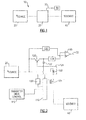
- Figure 1 illustrates an example solenoid control configuration 10 with a voltage source 20 providing power to a solenoid 40.
- the power flow to the solenoid 40 is controlled at least in part by a hardware control circuit 30.
- the hardware control circuit 30 includes a fault detection output 32 that can be connected to a software controller such as a general controller 50.
- the fault detection output 32 is a high (non-0 volt) signal when no overcurrent is present, and a low (0 volt) signal when an overcurrent is present.
- the fault detection output 32 is monitored by the general controller 50.
- the general controller 50 detects an overcurrent that persists for greater than a predefined time period, the general controller 50 determines that a fault is present and disconnects the voltage source 20 from the circuit, thereby preventing excessive current drawn from the voltage source 20.
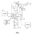
- FIG 2 illustrates a schematic diagram of the hardware controls 30 of the solenoid control configuration 10 of Figure 1 , with like numerals indicating like elements.
- the voltage source 20 is connected to the solenoid 40 via a resistor 102 and a high side solenoid switch 104.
- the high side solenoid switch 104 is a transistor. Current flow through the transistor is determined by the source to gate voltage of the transistor. The source to gate voltage of the transistor is referred to as the bias voltage.
- the bias voltage of the high side solenoid switch is controlled via a bias circuit 110.
- the bias circuit 110 is, in turn, controlled by a transistor drive control 112.
- the transistor drive control 112 can be part of the general controller 50 or an independent transistor controller.
- An overcurrent transistor 120 connects the voltage source 20 to a voltage divider 134.
- the output of the voltage divider 134 provides an input to a comparator 140.
- a second comparator input is provided from a second voltage divider 132.
- the second voltage divider 132 receives an input directly from the voltage source 20.
- Each of the voltage dividers 132, 134 scales the voltage by a known factor prior to passing the voltage to the comparator 140, thereby conditioning the voltage to be utilized by the comparator 140.
- the general controller 50 can monitor for a fault condition. If the overcurrent persists for longer than a predefined period, the general controller 50 determines that a fault is present and disconnects the voltage source 20.
- the overcurrent transistor 120 collector is additionally connected to a secondary bias circuit 150 through a diode 122.
- the diode 122 prevents current backflow through the secondary bias circuit 150 when no overcurrent exists.
- the control input of the overcurrent transistor 120 is the output of the sense resistor 102, and is configured such that the overcurrent transistor 120 transitions to the on state when current across the sense resistor 102 exceeds a threshold. Thus, the overcurrent transistor 120 remains in the off state unless an overcurrent is present.
- each of the voltage dividers 132, 134 is a standard voltage divider constructed of two resistors 230, 232, 234, 236 in series, with an output node between the two resistors.
- the bias circuit 110 includes two bias voltage resistors 212, 214 in series connecting the source and gate of the high side solenoid switch 104, thereby controlling the bias voltage of the high side solenoid switch 104.
- a transistor 216 connects a bias current resistors 218 at a node between each of the bias voltage resistors 212, 214. The resistance of the bias current resistor 218 controls the total amount of current drawn through the bias circuit 110.
- the current drawn through the bias circuit 110 is drawn from the bias voltage resistors 212, 214 which in turn draw the current from the voltage source 20.
- Current passing through the bias voltage resistors 212, 214 introduces a bias voltage to the high side solenoid switch 104.
- the bias voltage is sufficiently high, the high side solenoid switch 104 allows for virtually unfettered current flow, whereas when the bias voltage is low the amount of current that can pass through the high side solenoid switch 104 is limited according to known transistor principles.
- the secondary bias circuit 150 illustrated in the example of Figure 3 includes a capacitor 252 and a resistor 254 arrange in a parallel configuration.
- the availability of current through the newly opened current flow path reduces the current draw through the bias voltage resistors 212, 214.
- the reduced current draw causes a corresponding decrease in the voltage drop across the bias voltage resistors 212, 214 and a corresponding reduction in the bias voltage of the high side solenoid switch 104.
- the decreased bias voltage is sufficiently low to limit the amount of current that can pass through the high side solenoid switch 104, thus providing a currant limit during the overcurrent validation period.
Landscapes
- Engineering & Computer Science (AREA)
- Power Engineering (AREA)
- Emergency Protection Circuit Devices (AREA)
Applications Claiming Priority (1)
| Application Number | Priority Date | Filing Date | Title |
|---|---|---|---|
| US13/161,567 US8687333B2 (en) | 2011-06-16 | 2011-06-16 | Overcurrent limiting for high side solenoid switch controls |
Publications (3)
| Publication Number | Publication Date |
|---|---|
| EP2535995A2 true EP2535995A2 (fr) | 2012-12-19 |
| EP2535995A3 EP2535995A3 (fr) | 2015-12-16 |
| EP2535995B1 EP2535995B1 (fr) | 2021-09-29 |
Family
ID=46506145
Family Applications (1)
| Application Number | Title | Priority Date | Filing Date |
|---|---|---|---|
| EP12171690.6A Active EP2535995B1 (fr) | 2011-06-16 | 2012-06-12 | Limitation de surintensité pour commandes de commutateur de solénoïde côté alimentation |
Country Status (2)
| Country | Link |
|---|---|
| US (1) | US8687333B2 (fr) |
| EP (1) | EP2535995B1 (fr) |
Families Citing this family (4)
| Publication number | Priority date | Publication date | Assignee | Title |
|---|---|---|---|---|
| US9417983B2 (en) | 2013-06-03 | 2016-08-16 | Infineon Technologies Ag | Over-current detection for bus line drivers |
| US9172235B2 (en) * | 2013-06-03 | 2015-10-27 | Infineon Technologies Ag | Shutdown protection for bus line drivers |
| US10672549B2 (en) * | 2017-07-19 | 2020-06-02 | Hamilton Sunstrand Corporation | Solenoid diagnostics digital interface |
| JP7292196B2 (ja) * | 2019-12-16 | 2023-06-16 | 三菱電機株式会社 | 駆動装置およびパワーモジュール |
Family Cites Families (15)
| Publication number | Priority date | Publication date | Assignee | Title |
|---|---|---|---|---|
| US4529165A (en) | 1984-08-14 | 1985-07-16 | United Technologies Diesel Systems, Inc. | Solenoid valve |
| US4725801A (en) | 1986-10-24 | 1988-02-16 | Hamilton Standard Controls, Inc. | Bistable solenoid switch |
| US5347419A (en) | 1992-12-22 | 1994-09-13 | Eaton Corporation | Current limiting solenoid driver |
| KR0150133B1 (ko) | 1995-04-27 | 1998-10-01 | 김광호 | 비례 솔레노이드밸브 제어시스템 |
| US5621603A (en) | 1995-07-26 | 1997-04-15 | United Technologies Corporation | Pulse width modulated solenoid driver controller |
| US5815362A (en) * | 1996-12-04 | 1998-09-29 | Westinghouse Air Brake Company | Pulse width modulated drive for an infinitely variable solenoid operated brake cylinder pressure control valve |
| US20040052076A1 (en) | 1997-08-26 | 2004-03-18 | Mueller George G. | Controlled lighting methods and apparatus |
| JP3784594B2 (ja) * | 1999-11-30 | 2006-06-14 | 富士通株式会社 | 電流制御回路 |
| JP4055882B2 (ja) | 2000-08-31 | 2008-03-05 | 株式会社小松製作所 | ソレノイド駆動装置 |
| JP3914004B2 (ja) * | 2001-05-25 | 2007-05-16 | 矢崎総業株式会社 | 半導体素子の過電流検出・保護装置 |
| US6850402B2 (en) | 2002-03-01 | 2005-02-01 | Honeywell International Inc. | Circuit and method for controlling current flow through a solenoid |
| US7453678B2 (en) | 2004-08-24 | 2008-11-18 | Hamilton Sunstrand Corporation | Power interruption system for electronic circuit breaker |
| US7738225B2 (en) * | 2005-12-29 | 2010-06-15 | Micrel, Incorporated | Circuit and method for limiting power to a load |
| JP5099505B2 (ja) * | 2008-02-15 | 2012-12-19 | セイコーインスツル株式会社 | ボルテージレギュレータ |
| US8922961B2 (en) * | 2009-09-25 | 2014-12-30 | Hamilton Sundstrand Corporation | Two-level lightning protection circuit |
-
2011
- 2011-06-16 US US13/161,567 patent/US8687333B2/en active Active
-
2012
- 2012-06-12 EP EP12171690.6A patent/EP2535995B1/fr active Active
Non-Patent Citations (1)
| Title |
|---|
| None |
Also Published As
| Publication number | Publication date |
|---|---|
| EP2535995B1 (fr) | 2021-09-29 |
| US20120320478A1 (en) | 2012-12-20 |
| EP2535995A3 (fr) | 2015-12-16 |
| US8687333B2 (en) | 2014-04-01 |
Similar Documents
| Publication | Publication Date | Title |
|---|---|---|
| US10651837B2 (en) | Power supply device | |
| US9853467B2 (en) | Overcurrent protection in a battery charger | |
| US8040652B2 (en) | Programmable power distribution switches with two-level current sensing | |
| US9671465B2 (en) | Detecting faults in hot-swap applications | |
| EP2852018A2 (fr) | Commande d'appel avec de multiples commutateurs | |
| US11467611B2 (en) | Current limiting electronic fuse circuit | |
| US8901985B2 (en) | Semiconductor device | |
| US8331072B1 (en) | Timer controlled, short and open circuit fault detection with slew-rate boosted output driver | |
| KR20150048763A (ko) | 볼티지 레귤레이터 | |
| EP2535995B1 (fr) | Limitation de surintensité pour commandes de commutateur de solénoïde côté alimentation | |
| CN108923376B (zh) | 一种可自恢复的过流关断保护方法及电路 | |
| US20200395747A1 (en) | Short circuit protection circuit for semiconductor switching element | |
| JP5900949B2 (ja) | 電源故障検出回路および電源故障検出方法 | |
| KR101671087B1 (ko) | 시퀀서 아날로그 출력 유닛 | |
| US20180358806A1 (en) | Power supply control apparatus | |
| JP2009207279A (ja) | 過電流保護装置および電子機器 | |
| JP2014161186A (ja) | スイッチ回路、半導体装置及びバッテリ装置 | |
| US10747247B2 (en) | Power supply circuit | |
| KR101771803B1 (ko) | 과전류 보호 회로 및 방법 | |
| US7612550B2 (en) | Dropper type regulator | |
| KR102252366B1 (ko) | 배터리 상태 감시 회로 및 배터리 장치 | |
| EP2527947A2 (fr) | Systèmes et procédés de limitation de courant testable à réinitialisation de hoquet | |
| KR101030958B1 (ko) | 저전압 레귤레이터의 과전류 보호회로 | |
| US9891649B2 (en) | Voltage regulator | |
| US20220229454A1 (en) | Voltage regulator and in-vehicle backup power supply |
Legal Events
| Date | Code | Title | Description |
|---|---|---|---|
| PUAI | Public reference made under article 153(3) epc to a published international application that has entered the european phase |
Free format text: ORIGINAL CODE: 0009012 |
|
| AK | Designated contracting states |
Kind code of ref document: A2 Designated state(s): AL AT BE BG CH CY CZ DE DK EE ES FI FR GB GR HR HU IE IS IT LI LT LU LV MC MK MT NL NO PL PT RO RS SE SI SK SM TR |
|
| AX | Request for extension of the european patent |
Extension state: BA ME |
|
| PUAL | Search report despatched |
Free format text: ORIGINAL CODE: 0009013 |
|
| AK | Designated contracting states |
Kind code of ref document: A3 Designated state(s): AL AT BE BG CH CY CZ DE DK EE ES FI FR GB GR HR HU IE IS IT LI LT LU LV MC MK MT NL NO PL PT RO RS SE SI SK SM TR |
|
| AX | Request for extension of the european patent |
Extension state: BA ME |
|
| RIC1 | Information provided on ipc code assigned before grant |
Ipc: H02H 3/02 20060101ALI20151110BHEP Ipc: H02H 9/00 20060101AFI20151110BHEP Ipc: H02H 7/22 20060101ALN20151110BHEP Ipc: H02H 1/04 20060101ALI20151110BHEP Ipc: H02H 9/02 20060101ALI20151110BHEP |
|
| 17P | Request for examination filed |
Effective date: 20160616 |
|
| RBV | Designated contracting states (corrected) |
Designated state(s): AL AT BE BG CH CY CZ DE DK EE ES FI FR GB GR HR HU IE IS IT LI LT LU LV MC MK MT NL NO PL PT RO RS SE SI SK SM TR |
|
| STAA | Information on the status of an ep patent application or granted ep patent |
Free format text: STATUS: EXAMINATION IS IN PROGRESS |
|
| 17Q | First examination report despatched |
Effective date: 20190920 |
|
| STAA | Information on the status of an ep patent application or granted ep patent |
Free format text: STATUS: EXAMINATION IS IN PROGRESS |
|
| GRAP | Despatch of communication of intention to grant a patent |
Free format text: ORIGINAL CODE: EPIDOSNIGR1 |
|
| STAA | Information on the status of an ep patent application or granted ep patent |
Free format text: STATUS: GRANT OF PATENT IS INTENDED |
|
| INTG | Intention to grant announced |
Effective date: 20210503 |
|
| RAP3 | Party data changed (applicant data changed or rights of an application transferred) |
Owner name: HAMILTON SUNDSTRAND CORPORATION |
|
| GRAS | Grant fee paid |
Free format text: ORIGINAL CODE: EPIDOSNIGR3 |
|
| GRAA | (expected) grant |
Free format text: ORIGINAL CODE: 0009210 |
|
| STAA | Information on the status of an ep patent application or granted ep patent |
Free format text: STATUS: THE PATENT HAS BEEN GRANTED |
|
| AK | Designated contracting states |
Kind code of ref document: B1 Designated state(s): AL AT BE BG CH CY CZ DE DK EE ES FI FR GB GR HR HU IE IS IT LI LT LU LV MC MK MT NL NO PL PT RO RS SE SI SK SM TR |
|
| REG | Reference to a national code |
Ref country code: GB Ref legal event code: FG4D |
|
| REG | Reference to a national code |
Ref country code: CH Ref legal event code: EP Ref country code: AT Ref legal event code: REF Ref document number: 1435050 Country of ref document: AT Kind code of ref document: T Effective date: 20211015 |
|
| REG | Reference to a national code |
Ref country code: DE Ref legal event code: R096 Ref document number: 602012076782 Country of ref document: DE |
|
| REG | Reference to a national code |
Ref country code: IE Ref legal event code: FG4D |
|
| REG | Reference to a national code |
Ref country code: LT Ref legal event code: MG9D |
|
| PG25 | Lapsed in a contracting state [announced via postgrant information from national office to epo] |
Ref country code: FI Free format text: LAPSE BECAUSE OF FAILURE TO SUBMIT A TRANSLATION OF THE DESCRIPTION OR TO PAY THE FEE WITHIN THE PRESCRIBED TIME-LIMIT Effective date: 20210929 Ref country code: RS Free format text: LAPSE BECAUSE OF FAILURE TO SUBMIT A TRANSLATION OF THE DESCRIPTION OR TO PAY THE FEE WITHIN THE PRESCRIBED TIME-LIMIT Effective date: 20210929 Ref country code: NO Free format text: LAPSE BECAUSE OF FAILURE TO SUBMIT A TRANSLATION OF THE DESCRIPTION OR TO PAY THE FEE WITHIN THE PRESCRIBED TIME-LIMIT Effective date: 20211229 Ref country code: LT Free format text: LAPSE BECAUSE OF FAILURE TO SUBMIT A TRANSLATION OF THE DESCRIPTION OR TO PAY THE FEE WITHIN THE PRESCRIBED TIME-LIMIT Effective date: 20210929 Ref country code: BG Free format text: LAPSE BECAUSE OF FAILURE TO SUBMIT A TRANSLATION OF THE DESCRIPTION OR TO PAY THE FEE WITHIN THE PRESCRIBED TIME-LIMIT Effective date: 20211229 Ref country code: SE Free format text: LAPSE BECAUSE OF FAILURE TO SUBMIT A TRANSLATION OF THE DESCRIPTION OR TO PAY THE FEE WITHIN THE PRESCRIBED TIME-LIMIT Effective date: 20210929 Ref country code: HR Free format text: LAPSE BECAUSE OF FAILURE TO SUBMIT A TRANSLATION OF THE DESCRIPTION OR TO PAY THE FEE WITHIN THE PRESCRIBED TIME-LIMIT Effective date: 20210929 |
|
| REG | Reference to a national code |
Ref country code: NL Ref legal event code: MP Effective date: 20210929 |
|
| REG | Reference to a national code |
Ref country code: AT Ref legal event code: MK05 Ref document number: 1435050 Country of ref document: AT Kind code of ref document: T Effective date: 20210929 |
|
| PG25 | Lapsed in a contracting state [announced via postgrant information from national office to epo] |
Ref country code: LV Free format text: LAPSE BECAUSE OF FAILURE TO SUBMIT A TRANSLATION OF THE DESCRIPTION OR TO PAY THE FEE WITHIN THE PRESCRIBED TIME-LIMIT Effective date: 20210929 Ref country code: GR Free format text: LAPSE BECAUSE OF FAILURE TO SUBMIT A TRANSLATION OF THE DESCRIPTION OR TO PAY THE FEE WITHIN THE PRESCRIBED TIME-LIMIT Effective date: 20211230 |
|
| PG25 | Lapsed in a contracting state [announced via postgrant information from national office to epo] |
Ref country code: AT Free format text: LAPSE BECAUSE OF FAILURE TO SUBMIT A TRANSLATION OF THE DESCRIPTION OR TO PAY THE FEE WITHIN THE PRESCRIBED TIME-LIMIT Effective date: 20210929 |
|
| PG25 | Lapsed in a contracting state [announced via postgrant information from national office to epo] |
Ref country code: IS Free format text: LAPSE BECAUSE OF FAILURE TO SUBMIT A TRANSLATION OF THE DESCRIPTION OR TO PAY THE FEE WITHIN THE PRESCRIBED TIME-LIMIT Effective date: 20220129 Ref country code: SK Free format text: LAPSE BECAUSE OF FAILURE TO SUBMIT A TRANSLATION OF THE DESCRIPTION OR TO PAY THE FEE WITHIN THE PRESCRIBED TIME-LIMIT Effective date: 20210929 Ref country code: RO Free format text: LAPSE BECAUSE OF FAILURE TO SUBMIT A TRANSLATION OF THE DESCRIPTION OR TO PAY THE FEE WITHIN THE PRESCRIBED TIME-LIMIT Effective date: 20210929 Ref country code: PT Free format text: LAPSE BECAUSE OF FAILURE TO SUBMIT A TRANSLATION OF THE DESCRIPTION OR TO PAY THE FEE WITHIN THE PRESCRIBED TIME-LIMIT Effective date: 20220131 Ref country code: PL Free format text: LAPSE BECAUSE OF FAILURE TO SUBMIT A TRANSLATION OF THE DESCRIPTION OR TO PAY THE FEE WITHIN THE PRESCRIBED TIME-LIMIT Effective date: 20210929 Ref country code: NL Free format text: LAPSE BECAUSE OF FAILURE TO SUBMIT A TRANSLATION OF THE DESCRIPTION OR TO PAY THE FEE WITHIN THE PRESCRIBED TIME-LIMIT Effective date: 20210929 Ref country code: ES Free format text: LAPSE BECAUSE OF FAILURE TO SUBMIT A TRANSLATION OF THE DESCRIPTION OR TO PAY THE FEE WITHIN THE PRESCRIBED TIME-LIMIT Effective date: 20210929 Ref country code: EE Free format text: LAPSE BECAUSE OF FAILURE TO SUBMIT A TRANSLATION OF THE DESCRIPTION OR TO PAY THE FEE WITHIN THE PRESCRIBED TIME-LIMIT Effective date: 20210929 Ref country code: CZ Free format text: LAPSE BECAUSE OF FAILURE TO SUBMIT A TRANSLATION OF THE DESCRIPTION OR TO PAY THE FEE WITHIN THE PRESCRIBED TIME-LIMIT Effective date: 20210929 Ref country code: AL Free format text: LAPSE BECAUSE OF FAILURE TO SUBMIT A TRANSLATION OF THE DESCRIPTION OR TO PAY THE FEE WITHIN THE PRESCRIBED TIME-LIMIT Effective date: 20210929 |
|
| REG | Reference to a national code |
Ref country code: DE Ref legal event code: R097 Ref document number: 602012076782 Country of ref document: DE |
|
| PG25 | Lapsed in a contracting state [announced via postgrant information from national office to epo] |
Ref country code: DK Free format text: LAPSE BECAUSE OF FAILURE TO SUBMIT A TRANSLATION OF THE DESCRIPTION OR TO PAY THE FEE WITHIN THE PRESCRIBED TIME-LIMIT Effective date: 20210929 |
|
| PLBE | No opposition filed within time limit |
Free format text: ORIGINAL CODE: 0009261 |
|
| STAA | Information on the status of an ep patent application or granted ep patent |
Free format text: STATUS: NO OPPOSITION FILED WITHIN TIME LIMIT |
|
| 26N | No opposition filed |
Effective date: 20220630 |
|
| PG25 | Lapsed in a contracting state [announced via postgrant information from national office to epo] |
Ref country code: SI Free format text: LAPSE BECAUSE OF FAILURE TO SUBMIT A TRANSLATION OF THE DESCRIPTION OR TO PAY THE FEE WITHIN THE PRESCRIBED TIME-LIMIT Effective date: 20210929 |
|
| REG | Reference to a national code |
Ref country code: DE Ref legal event code: R119 Ref document number: 602012076782 Country of ref document: DE |
|
| PG25 | Lapsed in a contracting state [announced via postgrant information from national office to epo] |
Ref country code: MC Free format text: LAPSE BECAUSE OF FAILURE TO SUBMIT A TRANSLATION OF THE DESCRIPTION OR TO PAY THE FEE WITHIN THE PRESCRIBED TIME-LIMIT Effective date: 20210929 Ref country code: IT Free format text: LAPSE BECAUSE OF FAILURE TO SUBMIT A TRANSLATION OF THE DESCRIPTION OR TO PAY THE FEE WITHIN THE PRESCRIBED TIME-LIMIT Effective date: 20210929 |
|
| REG | Reference to a national code |
Ref country code: CH Ref legal event code: PL |
|
| REG | Reference to a national code |
Ref country code: BE Ref legal event code: MM Effective date: 20220630 |
|
| PG25 | Lapsed in a contracting state [announced via postgrant information from national office to epo] |
Ref country code: LU Free format text: LAPSE BECAUSE OF NON-PAYMENT OF DUE FEES Effective date: 20220612 Ref country code: LI Free format text: LAPSE BECAUSE OF NON-PAYMENT OF DUE FEES Effective date: 20220630 Ref country code: IE Free format text: LAPSE BECAUSE OF NON-PAYMENT OF DUE FEES Effective date: 20220612 Ref country code: CH Free format text: LAPSE BECAUSE OF NON-PAYMENT OF DUE FEES Effective date: 20220630 |
|
| PG25 | Lapsed in a contracting state [announced via postgrant information from national office to epo] |
Ref country code: DE Free format text: LAPSE BECAUSE OF NON-PAYMENT OF DUE FEES Effective date: 20230103 Ref country code: BE Free format text: LAPSE BECAUSE OF NON-PAYMENT OF DUE FEES Effective date: 20220630 |
|
| P01 | Opt-out of the competence of the unified patent court (upc) registered |
Effective date: 20230522 |
|
| PGFP | Annual fee paid to national office [announced via postgrant information from national office to epo] |
Ref country code: FR Payment date: 20230523 Year of fee payment: 12 |
|
| PGFP | Annual fee paid to national office [announced via postgrant information from national office to epo] |
Ref country code: GB Payment date: 20230524 Year of fee payment: 12 |
|
| PG25 | Lapsed in a contracting state [announced via postgrant information from national office to epo] |
Ref country code: HU Free format text: LAPSE BECAUSE OF FAILURE TO SUBMIT A TRANSLATION OF THE DESCRIPTION OR TO PAY THE FEE WITHIN THE PRESCRIBED TIME-LIMIT; INVALID AB INITIO Effective date: 20120612 |
|
| PG25 | Lapsed in a contracting state [announced via postgrant information from national office to epo] |
Ref country code: SM Free format text: LAPSE BECAUSE OF FAILURE TO SUBMIT A TRANSLATION OF THE DESCRIPTION OR TO PAY THE FEE WITHIN THE PRESCRIBED TIME-LIMIT Effective date: 20210929 Ref country code: MK Free format text: LAPSE BECAUSE OF FAILURE TO SUBMIT A TRANSLATION OF THE DESCRIPTION OR TO PAY THE FEE WITHIN THE PRESCRIBED TIME-LIMIT Effective date: 20210929 Ref country code: CY Free format text: LAPSE BECAUSE OF FAILURE TO SUBMIT A TRANSLATION OF THE DESCRIPTION OR TO PAY THE FEE WITHIN THE PRESCRIBED TIME-LIMIT Effective date: 20210929 |