EP2535535A1 - Mélangeur statique - Google Patents
Mélangeur statique Download PDFInfo
- Publication number
- EP2535535A1 EP2535535A1 EP12163743A EP12163743A EP2535535A1 EP 2535535 A1 EP2535535 A1 EP 2535535A1 EP 12163743 A EP12163743 A EP 12163743A EP 12163743 A EP12163743 A EP 12163743A EP 2535535 A1 EP2535535 A1 EP 2535535A1
- Authority
- EP
- European Patent Office
- Prior art keywords
- mixer according
- circumferential direction
- guide vanes
- coupling
- mixer
- Prior art date
- Legal status (The legal status is an assumption and is not a legal conclusion. Google has not performed a legal analysis and makes no representation as to the accuracy of the status listed.)
- Granted
Links
- 230000003068 static effect Effects 0.000 title claims abstract description 10
- 230000008878 coupling Effects 0.000 claims description 47
- 238000010168 coupling process Methods 0.000 claims description 47
- 238000005859 coupling reaction Methods 0.000 claims description 47
- 239000002184 metal Substances 0.000 claims description 16
- 238000002485 combustion reaction Methods 0.000 claims description 10
- 230000000295 complement effect Effects 0.000 claims description 3
- 238000009434 installation Methods 0.000 claims description 3
- 239000012530 fluid Substances 0.000 claims description 2
- 239000007789 gas Substances 0.000 description 16
- QGZKDVFQNNGYKY-UHFFFAOYSA-N Ammonia Chemical compound N QGZKDVFQNNGYKY-UHFFFAOYSA-N 0.000 description 8
- 239000003638 chemical reducing agent Substances 0.000 description 8
- 230000002093 peripheral effect Effects 0.000 description 8
- 238000011144 upstream manufacturing Methods 0.000 description 6
- 239000003054 catalyst Substances 0.000 description 5
- 238000004519 manufacturing process Methods 0.000 description 5
- 238000000034 method Methods 0.000 description 5
- CURLTUGMZLYLDI-UHFFFAOYSA-N Carbon dioxide Chemical compound O=C=O CURLTUGMZLYLDI-UHFFFAOYSA-N 0.000 description 4
- XSQUKJJJFZCRTK-UHFFFAOYSA-N Urea Chemical compound NC(N)=O XSQUKJJJFZCRTK-UHFFFAOYSA-N 0.000 description 4
- 229910021529 ammonia Inorganic materials 0.000 description 4
- 239000004202 carbamide Substances 0.000 description 4
- 238000002156 mixing Methods 0.000 description 4
- 230000003197 catalytic effect Effects 0.000 description 3
- 238000006460 hydrolysis reaction Methods 0.000 description 3
- MWUXSHHQAYIFBG-UHFFFAOYSA-N nitrogen oxide Inorganic materials O=[N] MWUXSHHQAYIFBG-UHFFFAOYSA-N 0.000 description 3
- OWIKHYCFFJSOEH-UHFFFAOYSA-N Isocyanic acid Chemical compound N=C=O OWIKHYCFFJSOEH-UHFFFAOYSA-N 0.000 description 2
- XLJMAIOERFSOGZ-UHFFFAOYSA-N anhydrous cyanic acid Natural products OC#N XLJMAIOERFSOGZ-UHFFFAOYSA-N 0.000 description 2
- 229910002092 carbon dioxide Inorganic materials 0.000 description 2
- 239000001569 carbon dioxide Substances 0.000 description 2
- 230000006835 compression Effects 0.000 description 2
- 238000007906 compression Methods 0.000 description 2
- 230000001419 dependent effect Effects 0.000 description 2
- 230000007062 hydrolysis Effects 0.000 description 2
- 238000002360 preparation method Methods 0.000 description 2
- 230000008569 process Effects 0.000 description 2
- 239000000243 solution Substances 0.000 description 2
- XLYOFNOQVPJJNP-UHFFFAOYSA-N water Substances O XLYOFNOQVPJJNP-UHFFFAOYSA-N 0.000 description 2
- 239000007864 aqueous solution Substances 0.000 description 1
- 238000005452 bending Methods 0.000 description 1
- 230000015556 catabolic process Effects 0.000 description 1
- 238000002788 crimping Methods 0.000 description 1
- 238000010586 diagram Methods 0.000 description 1
- 238000007599 discharging Methods 0.000 description 1
- 230000000694 effects Effects 0.000 description 1
- 238000001704 evaporation Methods 0.000 description 1
- 230000008020 evaporation Effects 0.000 description 1
- 230000009969 flowable effect Effects 0.000 description 1
- 238000000265 homogenisation Methods 0.000 description 1
- 238000002955 isolation Methods 0.000 description 1
- 239000007788 liquid Substances 0.000 description 1
- 230000009467 reduction Effects 0.000 description 1
- 230000035939 shock Effects 0.000 description 1
- 238000005476 soldering Methods 0.000 description 1
- 238000001149 thermolysis Methods 0.000 description 1
- 230000009466 transformation Effects 0.000 description 1
- 230000007704 transition Effects 0.000 description 1
- 238000003466 welding Methods 0.000 description 1
Images


Classifications
-
- B—PERFORMING OPERATIONS; TRANSPORTING
- B01—PHYSICAL OR CHEMICAL PROCESSES OR APPARATUS IN GENERAL
- B01F—MIXING, e.g. DISSOLVING, EMULSIFYING OR DISPERSING
- B01F23/00—Mixing according to the phases to be mixed, e.g. dispersing or emulsifying
- B01F23/20—Mixing gases with liquids
- B01F23/21—Mixing gases with liquids by introducing liquids into gaseous media
- B01F23/213—Mixing gases with liquids by introducing liquids into gaseous media by spraying or atomising of the liquids
- B01F23/2132—Mixing gases with liquids by introducing liquids into gaseous media by spraying or atomising of the liquids using nozzles
-
- B—PERFORMING OPERATIONS; TRANSPORTING
- B01—PHYSICAL OR CHEMICAL PROCESSES OR APPARATUS IN GENERAL
- B01F—MIXING, e.g. DISSOLVING, EMULSIFYING OR DISPERSING
- B01F25/00—Flow mixers; Mixers for falling materials, e.g. solid particles
- B01F25/30—Injector mixers
- B01F25/31—Injector mixers in conduits or tubes through which the main component flows
- B01F25/313—Injector mixers in conduits or tubes through which the main component flows wherein additional components are introduced in the centre of the conduit
- B01F25/3131—Injector mixers in conduits or tubes through which the main component flows wherein additional components are introduced in the centre of the conduit with additional mixing means other than injector mixers, e.g. screens, baffles or rotating elements
-
- B—PERFORMING OPERATIONS; TRANSPORTING
- B01—PHYSICAL OR CHEMICAL PROCESSES OR APPARATUS IN GENERAL
- B01F—MIXING, e.g. DISSOLVING, EMULSIFYING OR DISPERSING
- B01F25/00—Flow mixers; Mixers for falling materials, e.g. solid particles
- B01F25/40—Static mixers
- B01F25/42—Static mixers in which the mixing is affected by moving the components jointly in changing directions, e.g. in tubes provided with baffles or obstructions
- B01F25/43—Mixing tubes, e.g. wherein the material is moved in a radial or partly reversed direction
- B01F25/431—Straight mixing tubes with baffles or obstructions that do not cause substantial pressure drop; Baffles therefor
- B01F25/4315—Straight mixing tubes with baffles or obstructions that do not cause substantial pressure drop; Baffles therefor the baffles being deformed flat pieces of material
-
- F—MECHANICAL ENGINEERING; LIGHTING; HEATING; WEAPONS; BLASTING
- F01—MACHINES OR ENGINES IN GENERAL; ENGINE PLANTS IN GENERAL; STEAM ENGINES
- F01N—GAS-FLOW SILENCERS OR EXHAUST APPARATUS FOR MACHINES OR ENGINES IN GENERAL; GAS-FLOW SILENCERS OR EXHAUST APPARATUS FOR INTERNAL COMBUSTION ENGINES
- F01N3/00—Exhaust or silencing apparatus having means for purifying, rendering innocuous, or otherwise treating exhaust
- F01N3/08—Exhaust or silencing apparatus having means for purifying, rendering innocuous, or otherwise treating exhaust for rendering innocuous
- F01N3/10—Exhaust or silencing apparatus having means for purifying, rendering innocuous, or otherwise treating exhaust for rendering innocuous by thermal or catalytic conversion of noxious components of exhaust
- F01N3/18—Exhaust or silencing apparatus having means for purifying, rendering innocuous, or otherwise treating exhaust for rendering innocuous by thermal or catalytic conversion of noxious components of exhaust characterised by methods of operation; Control
- F01N3/20—Exhaust or silencing apparatus having means for purifying, rendering innocuous, or otherwise treating exhaust for rendering innocuous by thermal or catalytic conversion of noxious components of exhaust characterised by methods of operation; Control specially adapted for catalytic conversion ; Methods of operation or control of catalytic converters
- F01N3/2066—Selective catalytic reduction [SCR]
- F01N3/2073—Selective catalytic reduction [SCR] with means for generating a reducing substance from the exhaust gases
-
- F—MECHANICAL ENGINEERING; LIGHTING; HEATING; WEAPONS; BLASTING
- F01—MACHINES OR ENGINES IN GENERAL; ENGINE PLANTS IN GENERAL; STEAM ENGINES
- F01N—GAS-FLOW SILENCERS OR EXHAUST APPARATUS FOR MACHINES OR ENGINES IN GENERAL; GAS-FLOW SILENCERS OR EXHAUST APPARATUS FOR INTERNAL COMBUSTION ENGINES
- F01N3/00—Exhaust or silencing apparatus having means for purifying, rendering innocuous, or otherwise treating exhaust
- F01N3/08—Exhaust or silencing apparatus having means for purifying, rendering innocuous, or otherwise treating exhaust for rendering innocuous
- F01N3/10—Exhaust or silencing apparatus having means for purifying, rendering innocuous, or otherwise treating exhaust for rendering innocuous by thermal or catalytic conversion of noxious components of exhaust
- F01N3/24—Exhaust or silencing apparatus having means for purifying, rendering innocuous, or otherwise treating exhaust for rendering innocuous by thermal or catalytic conversion of noxious components of exhaust characterised by constructional aspects of converting apparatus
- F01N3/28—Construction of catalytic reactors
- F01N3/2892—Exhaust flow directors or the like, e.g. upstream of catalytic device
-
- B—PERFORMING OPERATIONS; TRANSPORTING
- B01—PHYSICAL OR CHEMICAL PROCESSES OR APPARATUS IN GENERAL
- B01F—MIXING, e.g. DISSOLVING, EMULSIFYING OR DISPERSING
- B01F25/00—Flow mixers; Mixers for falling materials, e.g. solid particles
- B01F25/40—Static mixers
- B01F25/42—Static mixers in which the mixing is affected by moving the components jointly in changing directions, e.g. in tubes provided with baffles or obstructions
- B01F25/43—Mixing tubes, e.g. wherein the material is moved in a radial or partly reversed direction
- B01F25/431—Straight mixing tubes with baffles or obstructions that do not cause substantial pressure drop; Baffles therefor
- B01F25/43197—Straight mixing tubes with baffles or obstructions that do not cause substantial pressure drop; Baffles therefor characterised by the mounting of the baffles or obstructions
- B01F25/431974—Support members, e.g. tubular collars, with projecting baffles fitted inside the mixing tube or adjacent to the inner wall
-
- F—MECHANICAL ENGINEERING; LIGHTING; HEATING; WEAPONS; BLASTING
- F01—MACHINES OR ENGINES IN GENERAL; ENGINE PLANTS IN GENERAL; STEAM ENGINES
- F01N—GAS-FLOW SILENCERS OR EXHAUST APPARATUS FOR MACHINES OR ENGINES IN GENERAL; GAS-FLOW SILENCERS OR EXHAUST APPARATUS FOR INTERNAL COMBUSTION ENGINES
- F01N2240/00—Combination or association of two or more different exhaust treating devices, or of at least one such device with an auxiliary device, not covered by indexing codes F01N2230/00 or F01N2250/00, one of the devices being
- F01N2240/20—Combination or association of two or more different exhaust treating devices, or of at least one such device with an auxiliary device, not covered by indexing codes F01N2230/00 or F01N2250/00, one of the devices being a flow director or deflector
-
- Y—GENERAL TAGGING OF NEW TECHNOLOGICAL DEVELOPMENTS; GENERAL TAGGING OF CROSS-SECTIONAL TECHNOLOGIES SPANNING OVER SEVERAL SECTIONS OF THE IPC; TECHNICAL SUBJECTS COVERED BY FORMER USPC CROSS-REFERENCE ART COLLECTIONS [XRACs] AND DIGESTS
- Y02—TECHNOLOGIES OR APPLICATIONS FOR MITIGATION OR ADAPTATION AGAINST CLIMATE CHANGE
- Y02A—TECHNOLOGIES FOR ADAPTATION TO CLIMATE CHANGE
- Y02A50/00—TECHNOLOGIES FOR ADAPTATION TO CLIMATE CHANGE in human health protection, e.g. against extreme weather
- Y02A50/20—Air quality improvement or preservation, e.g. vehicle emission control or emission reduction by using catalytic converters
Definitions
- the present invention relates to a static mixer for installation in a fluid line, in particular for installation in an exhaust pipe of an internal combustion engine, having the features of the preamble of claim 1.
- the invention also relates to an exhaust system for an internal combustion engine, in particular a motor vehicle, with at least one such Mixer is equipped.
- Modern exhaust systems of internal combustion engines may be equipped with an SCR system to reduce NOX emissions.
- an SCR system comprises a reducing agent supply device with the aid of which a suitable reducing agent, such as, for example, aqueous urea solution, can be introduced into an exhaust gas stream.
- a suitable reducing agent such as, for example, aqueous urea solution
- an SCR catalytic converter is arranged downstream of the reducing agent supply device, which reduces nitrogen oxides to water by means of ammonia.
- the reducing agent introduced in liquid form must be largely vaporized up to the SCR catalyst and mixed as homogeneously as possible with the exhaust gas stream.
- this mixing section which designates the distance from the reducing agent supply device to the SCR catalyst, can also be used to convert the introduced in aqueous solution of urea by hydrolysis reaction in ammonia and carbon dioxide.
- a thermolysis in which the urea is converted into ammonia and isocyanic acid.
- the actual hydrolysis takes place, in which the isocyanic acid is converted by means of water to ammonia and carbon dioxide.
- a static mixer which consists of a ring body having a row of blades with a plurality of ring body projecting inwardly from the guide vanes.
- the annular body is formed together with the guide vanes by a sheet metal part, which is made from a single sheet metal body by forming.
- a blank in the form of a flat sheet metal body is first cut several times to cut the vanes freely.
- the vanes are angled from the rest of the sheet metal body.
- the sheet metal body is bent with angled vanes about a transverse axis to its longitudinal axis until the peripheral ends abut. The production thus takes place in several steps, which is comparatively complicated, at least time-consuming.
- the present invention addresses the problem of providing for a static mixer of the type mentioned above, an improved or at least another embodiment, which is characterized in particular by an inexpensive manufacturability.
- This problem is solved according to the invention by the subject matters of the independent claims.
- Advantageous embodiments are the subject of the dependent claims.
- the invention is based on the general idea to assemble the annular body in the circumferential direction of at least two partial bodies, each partial body having a plurality of guide vanes. It has been found that the partial bodies with vanes made of blanks in the form of planar sheet metal bodies can be produced by a single forming process, in which within a single tool the guide vanes are cut free and angled, while at the same time the sheet metal body is bent about a bending axis extending transversely to its longitudinal direction, so as to produce in a single manufacturing step the respective partial body which corresponds to a circumferential segment of the annular body. With a ring body that extends over 360 ° closed, such a complex transformation can not be performed in a single operation.
- the ring body is assembled from two to four sub-bodies.
- an embodiment has been found in which the ring body is assembled from three sub-bodies.
- the circumferentially adjacent part body can engage in each other in the region of their circumferential ends and be pressed together.
- the adjacent body parts are positively connected with each other, without the need for elaborate cohesive connection measures, such as soldering and welding, must be performed.
- Possible attachment methods include, for example, clinching, clinching and crimping.
- the circumferentially adjacent sub-body can be arranged with their peripheral ends to shock.
- the circumferential ends of the circumferentially adjacent sub-bodies abut each other in the circumferential direction.
- the ring body also builds in the transition area flat between two adjacent sub-bodies.
- the annular body in the circumferential direction has a constant wall thickness.
- each partial body can have at least one coupling projection projecting in the circumferential direction at the one circumferential end and at least one coupling receptacle complementary thereto at the other peripheral end.
- the at least one coupling projection of the one partial body can now be brought into engagement with the at least one coupling receiver of the other partial body.
- the coupling projections and the coupling receptacles can be integrally formed on the part bodies, so that the provision of these coupling elements means no additional costs.
- coupling projection and coupling receptacle for forming a positive connection in particular for forming an undercut in the circumferential direction, be formed.
- the part body can be particularly easily set together.
- coupling protrusion and coupling receptacle such as the coupling elements of puzzle pieces may be configured to be, e.g. manually, easily engaged.
- the part body are identical parts.
- the annular body ultimately consists of two or more identical partial bodies, which are arranged adjacent to each other in the circumferential direction and connected to each other.
- the production costs for the individual parts can be reduced. If exactly two partial bodies are used for producing the annular body, each partial body extends over 180 ° in the circumferential direction. If exactly three partial bodies are used to produce the annular body, each partial body extends in the circumferential direction over 120 °. If there are four or more partial bodies, then corresponding peripheral sections result.
- the respective vane row is arranged on the annular body axially frontally.
- the respective row of vanes in which the vanes are adjacent in the circumferential direction, is located at the upstream end and at the downstream end, respectively, of the mixer and of the annular body.
- the annular body has a blade row on both axial end faces.
- the mixer has on the inflow and outflow side in each case a row of blades with circumferentially adjacent guide vanes. Due to the divided in the circumferential direction structure of the annular body thus also has the respective part body a plurality of upstream vanes and a plurality of downstream vanes.
- the vanes may have a position relative to the incoming exhaust flow such that they more or less deflect the incoming exhaust flow circumferentially.
- all the guide vanes have the same position relative to the exhaust gas flow, so that the flow through the blade row leads to a swirl in the exhaust gas flow.
- the flow direction of the exhaust gas corresponds to the axial direction of the mixer. If two rows of blades are now provided, the guide vanes of both blade rows can be set in the same direction with respect to the exhaust gas flow, so that the outflow-side blade row amplifies the swirl generated with the aid of the inflow side blade row. It is also possible to make the vanes of the two rows of blades in opposite directions with respect to the exhaust gas flow. As a result, the downstream side blade row reduces or eliminates the twist generated by the upstream side blade row. As a result, a particularly intensive mixing can be realized.
- the respective partial body can have at least one radial passage opening between the axial end faces of the annular body.
- a fixation of the body part within the forming tool can be particularly easily performed.
- this passage opening can also be used to fix the partial body in an exhaust pipe. For example, it is particularly easy to produce a weld in the area of the passage opening.
- the guide vanes in the respective row of blades may be arranged relative to one another without contact. This will Avoiding contact between blades of the same blade row, which avoids noise in the event of vibration.
- a plurality of guide vanes end radially inward on a circular core zone, while at least one guide blade protrudes into this core zone.
- the guide vanes can be attached to the respective part body.
- each part body is made integral with its vanes in one piece.
- each part of the body with its vanes is a sheet metal part, which is made of a single sheet metal body by forming.
- a method according to the invention for producing the mixer is characterized in that blanks which are formed by flat sheet metal pieces are each reshaped in a single forming tool into circular arc-shaped partial bodies with guide vanes projecting therefrom. The partial bodies are thereby end-formed and are tool-falling.
- An exhaust system according to the invention for an internal combustion engine, in particular of a motor vehicle comprises an exhaust pipe, in which at least one static mixer of the type described above is arranged. Upstream of this mixer the exhaust system can have a reducing agent supply device. Downstream of the mixer, the exhaust system may be equipped with an SCR catalyst.
- an internal combustion engine 1 comprises an engine block 2 with a plurality of combustion chambers 3 and an exhaust system 4 for discharging exhaust gases from the combustion chambers 3.
- the exhaust system 4 comprises an exhaust gas line 5, in which an SCR catalytic converter 6 is arranged. Upstream of the SCR catalytic converter 6, a reducing agent supply device 7 is connected to the exhaust gas line 5, with the aid of which a reducing agent 8, for example aqueous urea solution, can be introduced into the exhaust gas flow guided in the exhaust gas line 5. Between the Reduktionsffenzu slaughterhouse 7 and the SCR catalyst 6, a static mixer 9 is arranged in the exhaust pipe 5.
- the mixer 9 has according to the FIGS. 2 to 5 an annular body 10, which has at least one row of blades 11, wherein each row of blades 11 has a plurality of annular bodies 10 inwardly projecting vanes 12.
- the ring body 10 is composed of a plurality of partial bodies 14 which adjoin one another in the circumferential direction 13.
- the guide vanes 12 are formed integrally on the respective part body 14, so that the respective part body 14 together with its
- Guide vanes 12 is made of one piece. Particularly useful is the respective body part 14 together with its vanes 12, a sheet metal part, which is made from a single sheet metal body by forming.
- the partial bodies 14 can be configured such that they engage in one another in the region of their circumferential ends 15, 16 and are pressed together.
- the circumferential ends 15, 16 may be arranged in abutment, so that they rest against one another only in the circumferential direction 13 without radially overlapping or overlapping one another. In this way, a circumferentially continuous 13 wall thickness for the annular body 10 can be ensured.
- the respective partial body 14 has at the one circumferential end 15 a coupling projection 17 projecting in the circumferential direction 13 and at the other circumferential end 16 a coupling receiver 18 complementary to the coupling projection 17 FIG. 2 can be removed, are for connecting circumferentially 13 adjacent part bodies 14 of the coupling projection 17 of a partial body 14 and the coupling receptacle 18 of the other body part 14 with each other.
- coupling projection 17 and coupling receptacle 18 are expediently shaped in such a way that a form-fit connection can be produced. This is achieved in the example by an undercut with respect to the circumferential direction, the coupling projection 17 and in the coupling receptacle 18.
- the coupling projection 17 widens with increasing distance from the associated peripheral end 15.
- the coupling receptacle 18 tapers in the direction of the associated peripheral end 16.
- Coupling projection 17 and coupling receptacle 18 can be shaped in particular like the coupling elements of puzzle pieces and cooperate with one another.
- the individual part body 14 attached to each other, such that the coupling projections 17 engage in the associated coupling receptacles 18.
- a radial compression can be carried out, in which the coupling projections 17 in the circumferential direction 13 and axially, ie parallel to a in FIG.
- the partial bodies 14 are identical parts, so that in the present case three identical partial bodies 14 can be assembled to form the annular body 10.
- the ring body 10 has two blade rows 11, which are each arranged axially on the end face of the ring body 10.
- the assembly of the mixer 9 in the exhaust pipe 5 is such that the longitudinal central axis 19 of the annular body 10 extends parallel to the main flow direction of the exhaust gas in the exhaust pipe 5.
- the annular body 10 is positioned coaxially with the respective exhaust gas line 5.
- the two blade rows 11 can also be referred to as the inflow-side blade row 11 'and outflow-side blade row 11 ".
- the individual body parts 14 are then expediently also equipped for each blade row 11 with a plurality of guide vanes 12.
- the guide vanes 12 have an angle of attack or a position relative to the inflow direction of the exhaust gas. Within the same blade row 11, the employment of the associated guide vanes 12 is the same. Thus, the flow through the blade row 11 can act on the exhaust gas flow with a twist. In the example shown here, the guide vanes 12 of both rows of blades 11 have in the same direction employment, whereby the downstream-side blade row 11 "amplifies the twist of the upstream blade row 11 '.
- the respective partial body 14 may have at least one radial passage opening 20 which is arranged between the axial end faces of the annular body 10.
- the passage opening 20 can be used, for example, during the production of the respective part body 14 for fixing the blank body serving as a blank in an associated forming tool. Furthermore, as part of the assembly of the mixer 9 in the exhaust pipe 5 in the region of this passage opening fixation of the respective body part 14 and thus of the entire annular body 10 on the exhaust pipe 5 done.
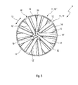
- the guide vanes 12 are arranged within the respective blade row 11 so that they do not touch each other. Furthermore, in FIG. 3 a circular core zone 21 recognizable. This core zone 21 is formed by the fact that within the respective blade row 11 a plurality of guide vanes 12 end radially inward at this core zone 21, such that the core zone 21 remains substantially free. In this way, in particular, it is achieved that the guide vanes 12 do not touch.
- the inflow-side blade row 11 ' has a plurality of guide vanes 12', which are longer than the other guide vanes 12 and accordingly protrude into the core zone 21.
- the freely flowable cross section can also be reduced in the region of the core zone 21. Because not all the vanes 12, but only a few vanes 12 'protrude into the core zone 21, can also ensure a non-contact positioning or a free-standing arrangement for these vanes 12'.
- the inflow-side blade row 11 ' has such longer guide blades 12', which protrude into the core zone 21.
- all guide vanes 12 are the same length and end at the core zone 21. Accordingly, the respective body part 14 has in each case at least one such longer guide blade 12 '.
- both blade rows 11 may be equipped with such longer guide blades 12 '. In another embodiment, it can also be provided that only the outflow-side blade row 11 "has such longer guide blades 12 '.
- the preparation of the mixer 9 is carried out such that from blanks, which are formed by planar sheet metal body, in a forming tool, in particular in a single forming process, the partial body 14 are endgeformt tool with the guide vanes 12. Subsequently, a plurality of body parts 14 are assembled to the ring body 10 and secured in the region of their peripheral ends 15, 16 to each other. For example, by radially compressing the abutting peripheral ends 15, 16 in the region of the intermeshing coupling projections 17 and coupling receivers 18. Subsequently, the annular body 10 and the mixer 9 is completed and can be installed in the exhaust pipe 5.
Applications Claiming Priority (1)
| Application Number | Priority Date | Filing Date | Title |
|---|---|---|---|
| DE102011077645A DE102011077645A1 (de) | 2011-06-16 | 2011-06-16 | Statischer Mischer |
Publications (2)
| Publication Number | Publication Date |
|---|---|
| EP2535535A1 true EP2535535A1 (fr) | 2012-12-19 |
| EP2535535B1 EP2535535B1 (fr) | 2014-12-17 |
Family
ID=46027631
Family Applications (1)
| Application Number | Title | Priority Date | Filing Date |
|---|---|---|---|
| EP12163743.3A Revoked EP2535535B1 (fr) | 2011-06-16 | 2012-04-11 | Mélangeur statique |
Country Status (4)
| Country | Link |
|---|---|
| US (1) | US10500550B2 (fr) |
| EP (1) | EP2535535B1 (fr) |
| JP (1) | JP2013002446A (fr) |
| DE (1) | DE102011077645A1 (fr) |
Cited By (5)
| Publication number | Priority date | Publication date | Assignee | Title |
|---|---|---|---|---|
| EP2769762A1 (fr) * | 2013-02-21 | 2014-08-27 | Toyota Jidosha Kabushiki Kaisha | Plaque de dispersion et appareil de dispersion |
| WO2015037559A1 (fr) * | 2013-09-12 | 2015-03-19 | フタバ産業株式会社 | Plaque de diffusion et son procédé de fabrication |
| EP3015672A1 (fr) * | 2014-10-31 | 2016-05-04 | Eberspächer Exhaust Technology GmbH & Co. KG | Dispositif de traitement de gaz d'échappement |
| WO2016203137A1 (fr) | 2015-06-17 | 2016-12-22 | Renault S.A.S | Systeme de depollution des gaz d'echappement optimise |
| EP3196434A1 (fr) * | 2016-01-21 | 2017-07-26 | Benteler Automobiltechnik GmbH | Scr système de post-traitement de gaz d'échappement |
Families Citing this family (23)
| Publication number | Priority date | Publication date | Assignee | Title |
|---|---|---|---|---|
| DE102010009043B4 (de) * | 2010-02-23 | 2013-11-07 | Iav Gmbh Ingenieurgesellschaft Auto Und Verkehr | Statischer Mischer für eine Abgasanlage einer Brennkraftmaschine |
| GB201207201D0 (en) * | 2012-04-24 | 2012-06-06 | Perkins Engines Co Ltd | Emissions cleaning module for a diesel engine |
| WO2013188726A1 (fr) * | 2012-06-15 | 2013-12-19 | Chemineer, Inc. | Mélangeur statique |
| JP6154185B2 (ja) * | 2013-04-30 | 2017-06-28 | フタバ産業株式会社 | 排気攪拌装置 |
| CN104329142B (zh) * | 2013-07-23 | 2017-04-12 | 埃贝斯佩歇排气技术有限责任两合公司 | 多级板式混合器 |
| DE102013223956A1 (de) * | 2013-11-22 | 2015-05-28 | Robert Bosch Gmbh | Einrichtung zur Abgasnachbehandlung |
| DE102015201378A1 (de) | 2014-01-29 | 2015-07-30 | Volkswagen Aktiengesellschaft | Mischer und Abgasanlage mit einem solchen |
| DE102014205158A1 (de) * | 2014-03-19 | 2015-09-24 | Eberspächer Exhaust Technology GmbH & Co. KG | Mischer für eine Abgasanlage |
| US9534525B2 (en) | 2015-05-27 | 2017-01-03 | Tenneco Automotive Operating Company Inc. | Mixer assembly for exhaust aftertreatment system |
| US10113468B2 (en) * | 2015-07-17 | 2018-10-30 | Middleville Tool & Die Co. | Mixer assembly for exhaust systems and method of forming the same |
| JP6435055B2 (ja) * | 2015-09-30 | 2018-12-05 | フタバ産業株式会社 | 排気管の製造方法 |
| US9909478B2 (en) | 2016-05-02 | 2018-03-06 | Caterpillar Inc. | Mixer for exhaust aftertreatment systems |
| US10012125B2 (en) | 2016-05-02 | 2018-07-03 | Caterpillar Inc. | Dual mixer for exhaust aftertreatment systems |
| GB2550173A (en) * | 2016-05-11 | 2017-11-15 | Perkins Engines Co Ltd | Mixer for after-treatment system |
| GB2598501B (en) * | 2016-12-12 | 2022-08-24 | Canada Pipeline Access Co Ltd | Static mixer for fluid flow in a pipeline |
| CN108167051A (zh) * | 2017-12-23 | 2018-06-15 | 无锡威孚力达催化净化器有限责任公司 | 一种scr后处理混合器结构 |
| DE112019000239T5 (de) | 2018-05-07 | 2020-08-27 | Canada Pipeline Accessories, Co. Ltd. | Rohrbaugruppe mit statischem mischer und strömungskonditionierer |
| GB2575674B8 (en) | 2018-07-19 | 2021-08-18 | Perkins Engines Co Ltd | Exhaust mixer, emissions cleaning module and method of manufacture |
| IT201800007427A1 (it) | 2018-07-23 | 2020-01-23 | Miscelatore statico per condotti di gas di scarico di motori endotermici, suo metodo di realizzazione e gruppo di scarico che incorpora il miscelatore. | |
| JP2020020532A (ja) * | 2018-08-01 | 2020-02-06 | 三菱電機株式会社 | 温度均一化装置、構造物およびパラボラアンテナ装置 |
| JP6776306B2 (ja) * | 2018-10-25 | 2020-10-28 | Primetals Technologies Japan株式会社 | スタティックミキサーおよびそれを備えた鋼板の燃焼設備 |
| USD976384S1 (en) | 2020-01-13 | 2023-01-24 | Canada Pipeline Accessories Co., Ltd. | Static mixer for fluid flow |
| US11247173B1 (en) * | 2020-08-11 | 2022-02-15 | Caterpillar Inc. | Two-stage mixer |
Citations (7)
| Publication number | Priority date | Publication date | Assignee | Title |
|---|---|---|---|---|
| US2685504A (en) * | 1953-03-26 | 1954-08-03 | Otmar M Ulbing | Fuel mixing device |
| DE2006017A1 (de) | 1969-02-14 | 1970-11-19 | Allmänna Svenska Elektriska Aktiebolaget, Västeras (Schweden) | Presse für isostatisches Pressen |
| US6109781A (en) * | 1999-02-16 | 2000-08-29 | Ogasawara; Toshiyuki | Element of a mixing apparatus |
| EP1686249A2 (fr) * | 2005-01-26 | 2006-08-02 | Jay S. Kim | Dispositif de turbillement de fluide pour un moteur à combustion interne |
| DE102007012790A1 (de) * | 2007-03-16 | 2008-09-18 | Audi Ag | Statischer Mischer für eine Abgasanlage einer Brennkraftmaschine |
| DE102008053106A1 (de) * | 2008-10-24 | 2010-04-29 | J. Eberspächer GmbH & Co. KG | Misch- und/oder Verdampfungseinrichtung und zugehöriges Herstellungsverfahren |
| EP2278133A2 (fr) * | 2009-07-25 | 2011-01-26 | J. Eberspächer GmbH & Co. KG | Dispositif de mélange et/ou d'évaporation |
Family Cites Families (38)
| Publication number | Priority date | Publication date | Assignee | Title |
|---|---|---|---|---|
| USRE20803E (en) | 1938-07-19 | Pneumatic brake | ||
| US3273601A (en) | 1966-09-20 | Stamped tubular product and method of making the same | ||
| US2690193A (en) * | 1948-01-26 | 1954-09-28 | Telford L Smith | Pipe clamp |
| US2882780A (en) * | 1955-09-20 | 1959-04-21 | Illinois Tool Works | Snap-in stud with deformable plastic engaging means |
| US3095337A (en) * | 1961-07-10 | 1963-06-25 | Gen Foam Plastics Corp | Semicylindrical foam elastomer insulation shell |
| US3751009A (en) * | 1972-03-02 | 1973-08-07 | Mc Hugh J | Motionless mixing device |
| US3898495A (en) * | 1974-04-05 | 1975-08-05 | Westinghouse Electric Corp | Circular fluorescent lamp with two-piece snap-lock base |
| US4298554A (en) * | 1977-11-14 | 1981-11-03 | Lebanon Steel Foundry | Coherent rigid solid material |
| US4316673A (en) * | 1978-08-08 | 1982-02-23 | General Dynamics, Pomona Division | Mixing device for simultaneously dispensing two-part liquid compounds from packaging kit |
| JPH0427373Y2 (fr) * | 1986-03-04 | 1992-07-01 | ||
| US4848920A (en) * | 1988-02-26 | 1989-07-18 | Husky Injection Molding Systems Ltd. | Static mixer |
| DK171572B1 (da) * | 1994-01-12 | 1997-01-20 | Topsoe Haldor As | Fremgangsmåde og indretning til blanding af gasser |
| EP0749776B1 (fr) * | 1995-06-21 | 2001-01-24 | Sulzer Chemtech AG | Mélangeur avec corps en forme de tube |
| CN1171485A (zh) * | 1996-03-18 | 1998-01-28 | 郑宜智 | 内燃机用气流旋涡装置及其制造方法 |
| USD414191S (en) * | 1997-06-23 | 1999-09-21 | Kim Sei Y | Air flow system for an internal combustion engine |
| KR100515233B1 (ko) | 1998-08-28 | 2005-09-16 | 킴벌리-클라크 월드와이드, 인크. | 비상사 유동의 혼합을 위한 장치 |
| ES2244514T3 (es) * | 2000-04-27 | 2005-12-16 | Sika Schweiz Ag | Elemento mezclador estatico y segmento de elemento mezclador, mezclador estatico y elemento de paletas mezcladoras, asi como su uso. |
| US6595395B2 (en) * | 2000-05-31 | 2003-07-22 | Valois S.A. | Dispenser having a fixing member, and a fixing member for such a dispenser |
| DE10248541A1 (de) * | 2002-10-17 | 2004-04-29 | Hilti Ag | Mischelement |
| DE602004032473D1 (de) * | 2004-02-16 | 2011-06-09 | Anemos Co Ltd | Mischelement und statischer fluidmischer damit |
| DE102006055036B4 (de) * | 2006-11-22 | 2023-03-02 | Faurecia Emissions Control Technologies, Germany Gmbh | Mischelement sowie Abgasanlage für eine Verbrennungskraftmaschine |
| DE102007009890A1 (de) * | 2007-02-28 | 2008-09-04 | Arvinmeritor Emissions Technologies Gmbh | Statisches Mischelement sowie Verfahren zur Herstellung eines statischen Mischelements |
| JP4824606B2 (ja) | 2007-03-13 | 2011-11-30 | 日立建機株式会社 | 建設機械 |
| US7908845B2 (en) * | 2007-04-16 | 2011-03-22 | GM Global Technology Operations LLC | Mixing apparatus for an exhaust after-treatment system |
| DE102007028449A1 (de) | 2007-04-25 | 2008-10-30 | J. Eberspächer GmbH & Co. KG | Misch- und/oder Verdampfungseinrichtung und zugehöriges Herstellungsverfahren |
| DE102007019878A1 (de) * | 2007-04-25 | 2008-11-06 | J. Eberspächer GmbH & Co. KG | Misch- und/oder Verdampfungseinrichtung und zugehöriges Herstellungsverfahren |
| DE202007010324U1 (de) | 2007-07-25 | 2008-11-27 | Heinrich Gillet Gmbh | Vorrichtung zum Nachbehandeln der Abgase von Dieselmotoren |
| DE102007048558A1 (de) * | 2007-10-09 | 2009-04-16 | Audi Ag | Statischer Mischer für eine Abgasanlage eines brennkraftmaschinenbetriebenen Fahrzeugs, insbesondere eines Kraftfahrzeugs |
| DE102008017395C5 (de) * | 2008-04-05 | 2018-01-25 | Eberspächer Exhaust Technology GmbH & Co. KG | Misch- und/oder Verdampfungseinrichtung |
| DE102008026724B4 (de) * | 2008-06-04 | 2013-11-28 | KÖNIG METALL GmbH & Co. KG | Verschluss für ein Rohr oder eine Platine |
| DE102008029110A1 (de) | 2008-06-20 | 2009-12-24 | J. Eberspächer GmbH & Co. KG | Misch- und/oder Verdampfungseinrichtung |
| US8397495B2 (en) * | 2008-06-26 | 2013-03-19 | Tenneco Automotive Operating Company Inc. | Exhaust gas additive/treatment system and mixer for use therein |
| JP2010221084A (ja) | 2009-03-19 | 2010-10-07 | Osaka Gas Co Ltd | 流体混合装置及び脱硝装置 |
| US8240137B2 (en) | 2009-10-27 | 2012-08-14 | Cummins Filtration Ip, Inc. | Reductant injection and decomposition system |
| US8375709B2 (en) * | 2009-11-17 | 2013-02-19 | Tenneco Automotive Operating Company Inc. | Exhaust gas additive/treatment system and mixer for use therein |
| US8935918B2 (en) * | 2010-04-23 | 2015-01-20 | GM Global Technology Operations LLC | Reconfigurable mixer for an exhaust aftertreatment system and method of using the same |
| DE102010021040A1 (de) * | 2010-05-19 | 2011-11-24 | J. Eberspächer GmbH & Co. KG | Mischer und Abgasanlage |
| US8966887B2 (en) * | 2011-04-08 | 2015-03-03 | GM Global Technology Operations LLC | Reconfigurable bi-metallic mixer for an exhaust aftertreatment system and method of using the same |
-
2011
- 2011-06-16 DE DE102011077645A patent/DE102011077645A1/de active Pending
-
2012
- 2012-04-11 EP EP12163743.3A patent/EP2535535B1/fr not_active Revoked
- 2012-06-14 JP JP2012135263A patent/JP2013002446A/ja active Pending
- 2012-06-15 US US13/524,372 patent/US10500550B2/en active Active
Patent Citations (7)
| Publication number | Priority date | Publication date | Assignee | Title |
|---|---|---|---|---|
| US2685504A (en) * | 1953-03-26 | 1954-08-03 | Otmar M Ulbing | Fuel mixing device |
| DE2006017A1 (de) | 1969-02-14 | 1970-11-19 | Allmänna Svenska Elektriska Aktiebolaget, Västeras (Schweden) | Presse für isostatisches Pressen |
| US6109781A (en) * | 1999-02-16 | 2000-08-29 | Ogasawara; Toshiyuki | Element of a mixing apparatus |
| EP1686249A2 (fr) * | 2005-01-26 | 2006-08-02 | Jay S. Kim | Dispositif de turbillement de fluide pour un moteur à combustion interne |
| DE102007012790A1 (de) * | 2007-03-16 | 2008-09-18 | Audi Ag | Statischer Mischer für eine Abgasanlage einer Brennkraftmaschine |
| DE102008053106A1 (de) * | 2008-10-24 | 2010-04-29 | J. Eberspächer GmbH & Co. KG | Misch- und/oder Verdampfungseinrichtung und zugehöriges Herstellungsverfahren |
| EP2278133A2 (fr) * | 2009-07-25 | 2011-01-26 | J. Eberspächer GmbH & Co. KG | Dispositif de mélange et/ou d'évaporation |
Cited By (7)
| Publication number | Priority date | Publication date | Assignee | Title |
|---|---|---|---|---|
| EP2769762A1 (fr) * | 2013-02-21 | 2014-08-27 | Toyota Jidosha Kabushiki Kaisha | Plaque de dispersion et appareil de dispersion |
| WO2015037559A1 (fr) * | 2013-09-12 | 2015-03-19 | フタバ産業株式会社 | Plaque de diffusion et son procédé de fabrication |
| EP3015672A1 (fr) * | 2014-10-31 | 2016-05-04 | Eberspächer Exhaust Technology GmbH & Co. KG | Dispositif de traitement de gaz d'échappement |
| US9765679B2 (en) | 2014-10-31 | 2017-09-19 | Eberspächer Exhaust Technology GmbH & Co. KG | Exhaust gas treatment device |
| WO2016203137A1 (fr) | 2015-06-17 | 2016-12-22 | Renault S.A.S | Systeme de depollution des gaz d'echappement optimise |
| EP3196434A1 (fr) * | 2016-01-21 | 2017-07-26 | Benteler Automobiltechnik GmbH | Scr système de post-traitement de gaz d'échappement |
| US10215074B2 (en) | 2016-01-21 | 2019-02-26 | Benteler Automobiltechnik Gmbh | SCR exhaust aftertreatment device |
Also Published As
| Publication number | Publication date |
|---|---|
| US10500550B2 (en) | 2019-12-10 |
| DE102011077645A1 (de) | 2012-12-20 |
| US20120320708A1 (en) | 2012-12-20 |
| JP2013002446A (ja) | 2013-01-07 |
| EP2535535B1 (fr) | 2014-12-17 |
Similar Documents
| Publication | Publication Date | Title |
|---|---|---|
| EP2535535B1 (fr) | Mélangeur statique | |
| EP1985356B1 (fr) | Dispositif de mélange et/ou d'évaporation | |
| EP2006017B1 (fr) | Dispositif de mélange et/ou d'évaporation et procédé de fabrication correspondant | |
| EP2022956B1 (fr) | Système d'échappement avec dispositif de guidage de l'écoulement | |
| EP1953359B1 (fr) | Dispositif d'échappement d'un moteur à combustion interne | |
| EP2979750B1 (fr) | Mélangeur et dispositif de mélange pour une installation de gaz d'échappement | |
| EP2097625B2 (fr) | Élément mélangeur et système d'échappement pour un moteur à combustion interne | |
| EP2278133B1 (fr) | Dispositif de mélange et/ou d'évaporation | |
| EP2980379B1 (fr) | Dispositif d'injection et procede de fabrication associe | |
| DE102012016423B3 (de) | Abgasanlage mit Misch- und oder Verdampfungseinrichtung | |
| EP2921220B1 (fr) | Mélangeur pour une installation de gaz d'échappement | |
| EP3015672B1 (fr) | Dispositif de traitement de gaz d'échappement | |
| DE102008017395C5 (de) | Misch- und/oder Verdampfungseinrichtung | |
| DE102008029110A1 (de) | Misch- und/oder Verdampfungseinrichtung | |
| EP3196434B1 (fr) | Scr système de post-traitement de gaz d'échappement | |
| WO2007115748A1 (fr) | Module de melange d'un fluide avec l'ecoulement de gaz d'echappement d'une installation de traitement des gaz d'echappement d'un vehicule automobile | |
| EP1835139A2 (fr) | Procédé de fabrication d'un dispositif de mélange pour un dispositif de traitement des gaz d'échappement, dispositif de mélange pour un dispositif de traitement des gaz d'échappement tout comme agencement doté d'un tel dispositif de mélange | |
| EP2616649B1 (fr) | Unité de traitement de gaz d'échappement, en particulier pour une conduite de recyclage de gaz d'échappement | |
| WO2012069292A1 (fr) | Silencieux | |
| DE102008053106B4 (de) | Misch- und/oder Verdampfungseinrichtung und zugehöriges Herstellungsverfahren | |
| WO2013087852A2 (fr) | Dispositif mélangeur | |
| DE102008054268B4 (de) | Misch- und/oder Verdampfungseinrichtung | |
| DE102014222395A1 (de) | Abgasanlage und Verfahren zur Herstellung einer solchen | |
| DE102008026724B4 (de) | Verschluss für ein Rohr oder eine Platine | |
| DE202021103290U1 (de) | Zylindrisches Gehäuse, Wärmeisolierabdeckung, Abgassystem, Verbindungselement und Werkzeugausrüstung |
Legal Events
| Date | Code | Title | Description |
|---|---|---|---|
| PUAI | Public reference made under article 153(3) epc to a published international application that has entered the european phase |
Free format text: ORIGINAL CODE: 0009012 |
|
| AK | Designated contracting states |
Kind code of ref document: A1 Designated state(s): AL AT BE BG CH CY CZ DE DK EE ES FI FR GB GR HR HU IE IS IT LI LT LU LV MC MK MT NL NO PL PT RO RS SE SI SK SM TR |
|
| AX | Request for extension of the european patent |
Extension state: BA ME |
|
| 17P | Request for examination filed |
Effective date: 20130516 |
|
| GRAP | Despatch of communication of intention to grant a patent |
Free format text: ORIGINAL CODE: EPIDOSNIGR1 |
|
| INTG | Intention to grant announced |
Effective date: 20140930 |
|
| GRAS | Grant fee paid |
Free format text: ORIGINAL CODE: EPIDOSNIGR3 |
|
| GRAA | (expected) grant |
Free format text: ORIGINAL CODE: 0009210 |
|
| AK | Designated contracting states |
Kind code of ref document: B1 Designated state(s): AL AT BE BG CH CY CZ DE DK EE ES FI FR GB GR HR HU IE IS IT LI LT LU LV MC MK MT NL NO PL PT RO RS SE SI SK SM TR |
|
| REG | Reference to a national code |
Ref country code: GB Ref legal event code: FG4D Free format text: NOT ENGLISH |
|
| REG | Reference to a national code |
Ref country code: CH Ref legal event code: EP |
|
| REG | Reference to a national code |
Ref country code: IE Ref legal event code: FG4D Free format text: LANGUAGE OF EP DOCUMENT: GERMAN |
|
| REG | Reference to a national code |
Ref country code: AT Ref legal event code: REF Ref document number: 702104 Country of ref document: AT Kind code of ref document: T Effective date: 20150115 |
|
| REG | Reference to a national code |
Ref country code: DE Ref legal event code: R096 Ref document number: 502012001821 Country of ref document: DE Effective date: 20150129 |
|
| REG | Reference to a national code |
Ref country code: FR Ref legal event code: PLFP Year of fee payment: 4 |
|
| PG25 | Lapsed in a contracting state [announced via postgrant information from national office to epo] |
Ref country code: FI Free format text: LAPSE BECAUSE OF FAILURE TO SUBMIT A TRANSLATION OF THE DESCRIPTION OR TO PAY THE FEE WITHIN THE PRESCRIBED TIME-LIMIT Effective date: 20141217 Ref country code: LT Free format text: LAPSE BECAUSE OF FAILURE TO SUBMIT A TRANSLATION OF THE DESCRIPTION OR TO PAY THE FEE WITHIN THE PRESCRIBED TIME-LIMIT Effective date: 20141217 Ref country code: NO Free format text: LAPSE BECAUSE OF FAILURE TO SUBMIT A TRANSLATION OF THE DESCRIPTION OR TO PAY THE FEE WITHIN THE PRESCRIBED TIME-LIMIT Effective date: 20150317 |
|
| REG | Reference to a national code |
Ref country code: LT Ref legal event code: MG4D |
|
| PG25 | Lapsed in a contracting state [announced via postgrant information from national office to epo] |
Ref country code: SE Free format text: LAPSE BECAUSE OF FAILURE TO SUBMIT A TRANSLATION OF THE DESCRIPTION OR TO PAY THE FEE WITHIN THE PRESCRIBED TIME-LIMIT Effective date: 20141217 Ref country code: GR Free format text: LAPSE BECAUSE OF FAILURE TO SUBMIT A TRANSLATION OF THE DESCRIPTION OR TO PAY THE FEE WITHIN THE PRESCRIBED TIME-LIMIT Effective date: 20150318 Ref country code: LV Free format text: LAPSE BECAUSE OF FAILURE TO SUBMIT A TRANSLATION OF THE DESCRIPTION OR TO PAY THE FEE WITHIN THE PRESCRIBED TIME-LIMIT Effective date: 20141217 Ref country code: HR Free format text: LAPSE BECAUSE OF FAILURE TO SUBMIT A TRANSLATION OF THE DESCRIPTION OR TO PAY THE FEE WITHIN THE PRESCRIBED TIME-LIMIT Effective date: 20141217 Ref country code: RS Free format text: LAPSE BECAUSE OF FAILURE TO SUBMIT A TRANSLATION OF THE DESCRIPTION OR TO PAY THE FEE WITHIN THE PRESCRIBED TIME-LIMIT Effective date: 20141217 |
|
| PG25 | Lapsed in a contracting state [announced via postgrant information from national office to epo] |
Ref country code: NL Free format text: LAPSE BECAUSE OF FAILURE TO SUBMIT A TRANSLATION OF THE DESCRIPTION OR TO PAY THE FEE WITHIN THE PRESCRIBED TIME-LIMIT Effective date: 20141217 |
|
| PG25 | Lapsed in a contracting state [announced via postgrant information from national office to epo] |
Ref country code: CZ Free format text: LAPSE BECAUSE OF FAILURE TO SUBMIT A TRANSLATION OF THE DESCRIPTION OR TO PAY THE FEE WITHIN THE PRESCRIBED TIME-LIMIT Effective date: 20141217 Ref country code: SK Free format text: LAPSE BECAUSE OF FAILURE TO SUBMIT A TRANSLATION OF THE DESCRIPTION OR TO PAY THE FEE WITHIN THE PRESCRIBED TIME-LIMIT Effective date: 20141217 Ref country code: RO Free format text: LAPSE BECAUSE OF FAILURE TO SUBMIT A TRANSLATION OF THE DESCRIPTION OR TO PAY THE FEE WITHIN THE PRESCRIBED TIME-LIMIT Effective date: 20141217 Ref country code: ES Free format text: LAPSE BECAUSE OF FAILURE TO SUBMIT A TRANSLATION OF THE DESCRIPTION OR TO PAY THE FEE WITHIN THE PRESCRIBED TIME-LIMIT Effective date: 20141217 Ref country code: EE Free format text: LAPSE BECAUSE OF FAILURE TO SUBMIT A TRANSLATION OF THE DESCRIPTION OR TO PAY THE FEE WITHIN THE PRESCRIBED TIME-LIMIT Effective date: 20141217 |
|
| REG | Reference to a national code |
Ref country code: DE Ref legal event code: R026 Ref document number: 502012001821 Country of ref document: DE |
|
| PLBI | Opposition filed |
Free format text: ORIGINAL CODE: 0009260 |
|
| PG25 | Lapsed in a contracting state [announced via postgrant information from national office to epo] |
Ref country code: IS Free format text: LAPSE BECAUSE OF FAILURE TO SUBMIT A TRANSLATION OF THE DESCRIPTION OR TO PAY THE FEE WITHIN THE PRESCRIBED TIME-LIMIT Effective date: 20150417 Ref country code: PL Free format text: LAPSE BECAUSE OF FAILURE TO SUBMIT A TRANSLATION OF THE DESCRIPTION OR TO PAY THE FEE WITHIN THE PRESCRIBED TIME-LIMIT Effective date: 20141217 |
|
| 26 | Opposition filed |
Opponent name: EBERSPAECHER EXHAUST TECHNOLOGY GMBH & CO. KG Effective date: 20150805 |
|
| REG | Reference to a national code |
Ref country code: DE Ref document number: 502012001821 Country of ref document: DE Ref legal event code: R082 Representative=s name: BRP RENAUD UND PARTNER MBB, DE Ref country code: DE Ref legal event code: R081 Ref document number: 502012001821 Country of ref document: DE Owner name: ROBERT BOSCH GMBH, DE Free format text: FORMER OWNER: BOSCH EMISSION SYSTEMS GMBH & CO. KG, 70469 STUTTGART, DE |
|
| PLAX | Notice of opposition and request to file observation + time limit sent |
Free format text: ORIGINAL CODE: EPIDOSNOBS2 |
|
| PG25 | Lapsed in a contracting state [announced via postgrant information from national office to epo] |
Ref country code: DK Free format text: LAPSE BECAUSE OF FAILURE TO SUBMIT A TRANSLATION OF THE DESCRIPTION OR TO PAY THE FEE WITHIN THE PRESCRIBED TIME-LIMIT Effective date: 20141217 |
|
| PG25 | Lapsed in a contracting state [announced via postgrant information from national office to epo] |
Ref country code: LU Free format text: LAPSE BECAUSE OF FAILURE TO SUBMIT A TRANSLATION OF THE DESCRIPTION OR TO PAY THE FEE WITHIN THE PRESCRIBED TIME-LIMIT Effective date: 20150411 Ref country code: MC Free format text: LAPSE BECAUSE OF FAILURE TO SUBMIT A TRANSLATION OF THE DESCRIPTION OR TO PAY THE FEE WITHIN THE PRESCRIBED TIME-LIMIT Effective date: 20141217 |
|
| REG | Reference to a national code |
Ref country code: CH Ref legal event code: PL |
|
| REG | Reference to a national code |
Ref country code: DE Ref legal event code: R082 Ref document number: 502012001821 Country of ref document: DE |
|
| PG25 | Lapsed in a contracting state [announced via postgrant information from national office to epo] |
Ref country code: IT Free format text: LAPSE BECAUSE OF FAILURE TO SUBMIT A TRANSLATION OF THE DESCRIPTION OR TO PAY THE FEE WITHIN THE PRESCRIBED TIME-LIMIT Effective date: 20141217 |
|
| REG | Reference to a national code |
Ref country code: IE Ref legal event code: MM4A |
|
| PG25 | Lapsed in a contracting state [announced via postgrant information from national office to epo] |
Ref country code: LI Free format text: LAPSE BECAUSE OF NON-PAYMENT OF DUE FEES Effective date: 20150430 Ref country code: CH Free format text: LAPSE BECAUSE OF NON-PAYMENT OF DUE FEES Effective date: 20150430 |
|
| PLAF | Information modified related to communication of a notice of opposition and request to file observations + time limit |
Free format text: ORIGINAL CODE: EPIDOSCOBS2 |
|
| PG25 | Lapsed in a contracting state [announced via postgrant information from national office to epo] |
Ref country code: SI Free format text: LAPSE BECAUSE OF FAILURE TO SUBMIT A TRANSLATION OF THE DESCRIPTION OR TO PAY THE FEE WITHIN THE PRESCRIBED TIME-LIMIT Effective date: 20141217 |
|
| RAP2 | Party data changed (patent owner data changed or rights of a patent transferred) |
Owner name: ROBERT BOSCH GMBH |
|
| REG | Reference to a national code |
Ref country code: FR Ref legal event code: PLFP Year of fee payment: 5 |
|
| PG25 | Lapsed in a contracting state [announced via postgrant information from national office to epo] |
Ref country code: IE Free format text: LAPSE BECAUSE OF NON-PAYMENT OF DUE FEES Effective date: 20150411 |
|
| PLBB | Reply of patent proprietor to notice(s) of opposition received |
Free format text: ORIGINAL CODE: EPIDOSNOBS3 |
|
| PG25 | Lapsed in a contracting state [announced via postgrant information from national office to epo] |
Ref country code: MT Free format text: LAPSE BECAUSE OF FAILURE TO SUBMIT A TRANSLATION OF THE DESCRIPTION OR TO PAY THE FEE WITHIN THE PRESCRIBED TIME-LIMIT Effective date: 20141217 |
|
| REG | Reference to a national code |
Ref country code: FR Ref legal event code: PLFP Year of fee payment: 6 |
|
| PG25 | Lapsed in a contracting state [announced via postgrant information from national office to epo] |
Ref country code: SM Free format text: LAPSE BECAUSE OF FAILURE TO SUBMIT A TRANSLATION OF THE DESCRIPTION OR TO PAY THE FEE WITHIN THE PRESCRIBED TIME-LIMIT Effective date: 20141217 Ref country code: BG Free format text: LAPSE BECAUSE OF FAILURE TO SUBMIT A TRANSLATION OF THE DESCRIPTION OR TO PAY THE FEE WITHIN THE PRESCRIBED TIME-LIMIT Effective date: 20141217 Ref country code: HU Free format text: LAPSE BECAUSE OF FAILURE TO SUBMIT A TRANSLATION OF THE DESCRIPTION OR TO PAY THE FEE WITHIN THE PRESCRIBED TIME-LIMIT; INVALID AB INITIO Effective date: 20120411 |
|
| PG25 | Lapsed in a contracting state [announced via postgrant information from national office to epo] |
Ref country code: CY Free format text: LAPSE BECAUSE OF FAILURE TO SUBMIT A TRANSLATION OF THE DESCRIPTION OR TO PAY THE FEE WITHIN THE PRESCRIBED TIME-LIMIT Effective date: 20141217 |
|
| PG25 | Lapsed in a contracting state [announced via postgrant information from national office to epo] |
Ref country code: PT Free format text: LAPSE BECAUSE OF FAILURE TO SUBMIT A TRANSLATION OF THE DESCRIPTION OR TO PAY THE FEE WITHIN THE PRESCRIBED TIME-LIMIT Effective date: 20150417 Ref country code: BE Free format text: LAPSE BECAUSE OF NON-PAYMENT OF DUE FEES Effective date: 20150430 |
|
| PGFP | Annual fee paid to national office [announced via postgrant information from national office to epo] |
Ref country code: FR Payment date: 20170424 Year of fee payment: 6 Ref country code: GB Payment date: 20170425 Year of fee payment: 6 |
|
| PG25 | Lapsed in a contracting state [announced via postgrant information from national office to epo] |
Ref country code: TR Free format text: LAPSE BECAUSE OF FAILURE TO SUBMIT A TRANSLATION OF THE DESCRIPTION OR TO PAY THE FEE WITHIN THE PRESCRIBED TIME-LIMIT Effective date: 20141217 |
|
| REG | Reference to a national code |
Ref country code: DE Ref legal event code: R064 Ref document number: 502012001821 Country of ref document: DE Ref country code: DE Ref legal event code: R103 Ref document number: 502012001821 Country of ref document: DE |
|
| RDAF | Communication despatched that patent is revoked |
Free format text: ORIGINAL CODE: EPIDOSNREV1 |
|
| PGFP | Annual fee paid to national office [announced via postgrant information from national office to epo] |
Ref country code: DE Payment date: 20170623 Year of fee payment: 6 |
|
| RDAG | Patent revoked |
Free format text: ORIGINAL CODE: 0009271 |
|
| STAA | Information on the status of an ep patent application or granted ep patent |
Free format text: STATUS: PATENT REVOKED |
|
| 27W | Patent revoked |
Effective date: 20170926 |
|
| GBPR | Gb: patent revoked under art. 102 of the ep convention designating the uk as contracting state |
Effective date: 20170926 |
|
| REG | Reference to a national code |
Ref country code: AT Ref legal event code: MA03 Ref document number: 702104 Country of ref document: AT Kind code of ref document: T Effective date: 20170926 |
|
| PG25 | Lapsed in a contracting state [announced via postgrant information from national office to epo] |
Ref country code: AL Free format text: LAPSE BECAUSE OF FAILURE TO SUBMIT A TRANSLATION OF THE DESCRIPTION OR TO PAY THE FEE WITHIN THE PRESCRIBED TIME-LIMIT Effective date: 20141217 |