EP2534502B1 - Ultrasound imaging system using beamforming techniques for phase coherence grating lobe suppression - Google Patents
Ultrasound imaging system using beamforming techniques for phase coherence grating lobe suppression Download PDFInfo
- Publication number
- EP2534502B1 EP2534502B1 EP11739471.8A EP11739471A EP2534502B1 EP 2534502 B1 EP2534502 B1 EP 2534502B1 EP 11739471 A EP11739471 A EP 11739471A EP 2534502 B1 EP2534502 B1 EP 2534502B1
- Authority
- EP
- European Patent Office
- Prior art keywords
- transmit
- array
- apertures
- sub
- ultrasound
- Prior art date
- Legal status (The legal status is an assumption and is not a legal conclusion. Google has not performed a legal analysis and makes no representation as to the accuracy of the status listed.)
- Active
Links
- 238000000034 method Methods 0.000 title claims description 84
- 238000012285 ultrasound imaging Methods 0.000 title claims description 33
- 230000001629 suppression Effects 0.000 title description 24
- 238000002592 echocardiography Methods 0.000 claims description 50
- 238000002604 ultrasonography Methods 0.000 claims description 40
- 238000003384 imaging method Methods 0.000 claims description 35
- 238000012545 processing Methods 0.000 claims description 23
- 230000001934 delay Effects 0.000 claims description 16
- 230000005540 biological transmission Effects 0.000 claims description 6
- 239000011295 pitch Substances 0.000 description 55
- 238000003491 array Methods 0.000 description 30
- 230000005855 radiation Effects 0.000 description 18
- 230000002123 temporal effect Effects 0.000 description 11
- 238000003672 processing method Methods 0.000 description 9
- 230000006870 function Effects 0.000 description 8
- 238000004519 manufacturing process Methods 0.000 description 7
- 230000014509 gene expression Effects 0.000 description 6
- 230000033001 locomotion Effects 0.000 description 6
- 238000005259 measurement Methods 0.000 description 5
- 238000004904 shortening Methods 0.000 description 5
- 238000013459 approach Methods 0.000 description 4
- 238000012937 correction Methods 0.000 description 4
- 230000003247 decreasing effect Effects 0.000 description 4
- 230000003111 delayed effect Effects 0.000 description 4
- 238000011161 development Methods 0.000 description 4
- 230000000694 effects Effects 0.000 description 4
- 238000004806 packaging method and process Methods 0.000 description 4
- 230000009467 reduction Effects 0.000 description 4
- 238000013519 translation Methods 0.000 description 4
- 238000004965 Hartree-Fock calculation Methods 0.000 description 3
- 230000001427 coherent effect Effects 0.000 description 3
- 238000009795 derivation Methods 0.000 description 3
- 239000003814 drug Substances 0.000 description 3
- 230000009977 dual effect Effects 0.000 description 3
- 230000005284 excitation Effects 0.000 description 3
- 230000006872 improvement Effects 0.000 description 3
- 238000012601 sigmoid curve-fitting method Methods 0.000 description 3
- 238000004088 simulation Methods 0.000 description 3
- 230000004075 alteration Effects 0.000 description 2
- 238000004458 analytical method Methods 0.000 description 2
- 230000004888 barrier function Effects 0.000 description 2
- 230000008859 change Effects 0.000 description 2
- 230000008569 process Effects 0.000 description 2
- NCGICGYLBXGBGN-UHFFFAOYSA-N 3-morpholin-4-yl-1-oxa-3-azonia-2-azanidacyclopent-3-en-5-imine;hydrochloride Chemical compound Cl.[N-]1OC(=N)C=[N+]1N1CCOCC1 NCGICGYLBXGBGN-UHFFFAOYSA-N 0.000 description 1
- 241001465754 Metazoa Species 0.000 description 1
- 230000015572 biosynthetic process Effects 0.000 description 1
- 210000004204 blood vessel Anatomy 0.000 description 1
- 238000013329 compounding Methods 0.000 description 1
- 238000004590 computer program Methods 0.000 description 1
- 208000031513 cyst Diseases 0.000 description 1
- 230000007423 decrease Effects 0.000 description 1
- 230000001419 dependent effect Effects 0.000 description 1
- 238000013461 design Methods 0.000 description 1
- 238000003745 diagnosis Methods 0.000 description 1
- 238000002059 diagnostic imaging Methods 0.000 description 1
- 238000010586 diagram Methods 0.000 description 1
- 208000037265 diseases, disorders, signs and symptoms Diseases 0.000 description 1
- 239000006185 dispersion Substances 0.000 description 1
- 229940079593 drug Drugs 0.000 description 1
- 238000001839 endoscopy Methods 0.000 description 1
- 238000005516 engineering process Methods 0.000 description 1
- 238000005290 field theory Methods 0.000 description 1
- 238000010304 firing Methods 0.000 description 1
- 238000012544 monitoring process Methods 0.000 description 1
- 230000000737 periodic effect Effects 0.000 description 1
- 230000010363 phase shift Effects 0.000 description 1
- 238000011158 quantitative evaluation Methods 0.000 description 1
- 230000004044 response Effects 0.000 description 1
- 230000035945 sensitivity Effects 0.000 description 1
- 239000000126 substance Substances 0.000 description 1
- 238000010408 sweeping Methods 0.000 description 1
- 238000003786 synthesis reaction Methods 0.000 description 1
- 230000001225 therapeutic effect Effects 0.000 description 1
- 230000000699 topical effect Effects 0.000 description 1
- 238000012800 visualization Methods 0.000 description 1
Images


Classifications
-
- A—HUMAN NECESSITIES
- A61—MEDICAL OR VETERINARY SCIENCE; HYGIENE
- A61B—DIAGNOSIS; SURGERY; IDENTIFICATION
- A61B8/00—Diagnosis using ultrasonic, sonic or infrasonic waves
- A61B8/52—Devices using data or image processing specially adapted for diagnosis using ultrasonic, sonic or infrasonic waves
- A61B8/5269—Devices using data or image processing specially adapted for diagnosis using ultrasonic, sonic or infrasonic waves involving detection or reduction of artifacts
-
- A—HUMAN NECESSITIES
- A61—MEDICAL OR VETERINARY SCIENCE; HYGIENE
- A61B—DIAGNOSIS; SURGERY; IDENTIFICATION
- A61B8/00—Diagnosis using ultrasonic, sonic or infrasonic waves
- A61B8/13—Tomography
- A61B8/14—Echo-tomography
- A61B8/145—Echo-tomography characterised by scanning multiple planes
-
- A—HUMAN NECESSITIES
- A61—MEDICAL OR VETERINARY SCIENCE; HYGIENE
- A61B—DIAGNOSIS; SURGERY; IDENTIFICATION
- A61B8/00—Diagnosis using ultrasonic, sonic or infrasonic waves
- A61B8/44—Constructional features of the ultrasonic, sonic or infrasonic diagnostic device
- A61B8/4483—Constructional features of the ultrasonic, sonic or infrasonic diagnostic device characterised by features of the ultrasound transducer
-
- A—HUMAN NECESSITIES
- A61—MEDICAL OR VETERINARY SCIENCE; HYGIENE
- A61B—DIAGNOSIS; SURGERY; IDENTIFICATION
- A61B8/00—Diagnosis using ultrasonic, sonic or infrasonic waves
- A61B8/52—Devices using data or image processing specially adapted for diagnosis using ultrasonic, sonic or infrasonic waves
- A61B8/5207—Devices using data or image processing specially adapted for diagnosis using ultrasonic, sonic or infrasonic waves involving processing of raw data to produce diagnostic data, e.g. for generating an image
-
- G—PHYSICS
- G01—MEASURING; TESTING
- G01S—RADIO DIRECTION-FINDING; RADIO NAVIGATION; DETERMINING DISTANCE OR VELOCITY BY USE OF RADIO WAVES; LOCATING OR PRESENCE-DETECTING BY USE OF THE REFLECTION OR RERADIATION OF RADIO WAVES; ANALOGOUS ARRANGEMENTS USING OTHER WAVES
- G01S15/00—Systems using the reflection or reradiation of acoustic waves, e.g. sonar systems
- G01S15/88—Sonar systems specially adapted for specific applications
- G01S15/89—Sonar systems specially adapted for specific applications for mapping or imaging
- G01S15/8906—Short-range imaging systems; Acoustic microscope systems using pulse-echo techniques
- G01S15/8909—Short-range imaging systems; Acoustic microscope systems using pulse-echo techniques using a static transducer configuration
- G01S15/8915—Short-range imaging systems; Acoustic microscope systems using pulse-echo techniques using a static transducer configuration using a transducer array
- G01S15/8927—Short-range imaging systems; Acoustic microscope systems using pulse-echo techniques using a static transducer configuration using a transducer array using simultaneously or sequentially two or more subarrays or subapertures
-
- G—PHYSICS
- G01—MEASURING; TESTING
- G01S—RADIO DIRECTION-FINDING; RADIO NAVIGATION; DETERMINING DISTANCE OR VELOCITY BY USE OF RADIO WAVES; LOCATING OR PRESENCE-DETECTING BY USE OF THE REFLECTION OR RERADIATION OF RADIO WAVES; ANALOGOUS ARRANGEMENTS USING OTHER WAVES
- G01S15/00—Systems using the reflection or reradiation of acoustic waves, e.g. sonar systems
- G01S15/88—Sonar systems specially adapted for specific applications
- G01S15/89—Sonar systems specially adapted for specific applications for mapping or imaging
- G01S15/8906—Short-range imaging systems; Acoustic microscope systems using pulse-echo techniques
- G01S15/895—Short-range imaging systems; Acoustic microscope systems using pulse-echo techniques characterised by the transmitted frequency spectrum
- G01S15/8956—Short-range imaging systems; Acoustic microscope systems using pulse-echo techniques characterised by the transmitted frequency spectrum using frequencies at or above 20 MHz
-
- G—PHYSICS
- G01—MEASURING; TESTING
- G01S—RADIO DIRECTION-FINDING; RADIO NAVIGATION; DETERMINING DISTANCE OR VELOCITY BY USE OF RADIO WAVES; LOCATING OR PRESENCE-DETECTING BY USE OF THE REFLECTION OR RERADIATION OF RADIO WAVES; ANALOGOUS ARRANGEMENTS USING OTHER WAVES
- G01S15/00—Systems using the reflection or reradiation of acoustic waves, e.g. sonar systems
- G01S15/88—Sonar systems specially adapted for specific applications
- G01S15/89—Sonar systems specially adapted for specific applications for mapping or imaging
- G01S15/8906—Short-range imaging systems; Acoustic microscope systems using pulse-echo techniques
- G01S15/8997—Short-range imaging systems; Acoustic microscope systems using pulse-echo techniques using synthetic aperture techniques
-
- G—PHYSICS
- G01—MEASURING; TESTING
- G01S—RADIO DIRECTION-FINDING; RADIO NAVIGATION; DETERMINING DISTANCE OR VELOCITY BY USE OF RADIO WAVES; LOCATING OR PRESENCE-DETECTING BY USE OF THE REFLECTION OR RERADIATION OF RADIO WAVES; ANALOGOUS ARRANGEMENTS USING OTHER WAVES
- G01S7/00—Details of systems according to groups G01S13/00, G01S15/00, G01S17/00
- G01S7/52—Details of systems according to groups G01S13/00, G01S15/00, G01S17/00 of systems according to group G01S15/00
- G01S7/52017—Details of systems according to groups G01S13/00, G01S15/00, G01S17/00 of systems according to group G01S15/00 particularly adapted to short-range imaging
- G01S7/52046—Techniques for image enhancement involving transmitter or receiver
- G01S7/52047—Techniques for image enhancement involving transmitter or receiver for elimination of side lobes or of grating lobes; for increasing resolving power
-
- G—PHYSICS
- G10—MUSICAL INSTRUMENTS; ACOUSTICS
- G10K—SOUND-PRODUCING DEVICES; METHODS OR DEVICES FOR PROTECTING AGAINST, OR FOR DAMPING, NOISE OR OTHER ACOUSTIC WAVES IN GENERAL; ACOUSTICS NOT OTHERWISE PROVIDED FOR
- G10K11/00—Methods or devices for transmitting, conducting or directing sound in general; Methods or devices for protecting against, or for damping, noise or other acoustic waves in general
- G10K11/18—Methods or devices for transmitting, conducting or directing sound
- G10K11/26—Sound-focusing or directing, e.g. scanning
- G10K11/34—Sound-focusing or directing, e.g. scanning using electrical steering of transducer arrays, e.g. beam steering
- G10K11/341—Circuits therefor
- G10K11/346—Circuits therefor using phase variation
Definitions
- This invention relates generally to ultrasound imaging systems, and more particularly to suppressing grating lobes in an ultrasound imaging system.
- Low-frequency ultrasound imaging systems are very commonly used in diagnostic medicine, and they have been used for over 50 years.
- New high-frequency ultrasound imaging technology offers dramatic improvements in image resolution compared to these conventional low-frequency systems.
- Synthetic aperture beamforming is not suitable for use in high-frequency ultrasound imaging where small vibrations can create phase shifts in the received signals.
- synthetic aperture beamforming can produce high frame rates for generating full 2D images, all of the elements need to be pulsed individually before the beamforming delays are inserted. This means that this beamforming technique is susceptible to image distortion due to the large amount of time expired during the acquisition of the pre-beamformed signals. This image distortion is avoided however when implementing transmit focal-zone beamforming. Although only one A-scan line can be collected per transmit event, image distortion due to small motion artifacts is avoided due to the small amount of time expired between beamforming events.
- phase coherence imaging creates very long pulses in the grating lobe region which, upon returning to the array elements, create very long narrow band receive pulses. Consequently, when phase coherence correction factors are calculated from the received echoes in the same temporal region as the main lobe, there are no longer any random phases present since all of the long grating lobe echoes now overlap and for a certain time duration, are virtually all in-phase.
- US Patent Pub No. US2005/0228279 discloses a method whereby ultrasound imaging adapts as a function of a coherence factor.
- Various beamforming, image forming or image processing parameters are varied as a function of a coherence factor to improve detail resolution, contrast resolution, dynamic range or SNR.
- a beamforming parameter such as the transmit or receive aperture size, apodization type or delay is selected to provide maximum coherence.
- an image forming parameter such as the number of beams for coherent synthesis or incoherent compounding, is set as a function of the coherence factor.
- an image processing parameter such as the dynamic range, linear or nonlinear video filter and/or linear or nonlinear map may also adapt as a function of the coherence factor.
- US Patent Pub. No. US2009/0131957 discloses sidelobe and clutter suppression techniques in ultrasound imaging, which are referred to as Dual Apodization with Cross-correlation or "DAX".
- DAX dramatically improves the contrast-to-noise ratio (CNR) allowing for easier visualization of anechoic cysts and blood vessels.
- CNR contrast-to-noise ratio
- These techniques use dual apodization or weighting strategies that are effective in removing or minimizing clutter and efficient in terms of computational load and hardware/software needs. This dual apodization allows for determination of the amount of mainlobe versus clutter contribution in a signal by cross-correlating RF data acquired from two apodization functions.
- WO 2010/018282 discloses a method and apparatus enabling the real-time correction and improvement of the quality of ultrasound images obtained using traditional methods.
- the invention consists of multiplying the formed samples by phase coherence factors (CF(K)) based on an analysis of the dispersion of the phases of the aperture data (S)(0).
- CF(K) phase coherence factors
- Johnson et al. discloses a coherent array imaging method-phased subarray (PSA) imaging-that performs partial transmit and receive beamforming using a subset of adjacent elements at each firing step.
- This method reduces the number of active channels to the number of subarray elements; these channels are multiplexed across the full array and a reduced number of beams are acquired from each subarray.
- the low-resolution subarray images are laterally upsampled, interpolated, weighted, and coherently summed to form the final high-resolution PSA image.
- the PSA imaging reduces the complexity of the front-end hardware while achieving image quality approaching that of FPA imaging.
- the present disclosure addresses long-felt needs in the field of ultrasound imaging by providing systems and methods for effectively reducing the temporal length of transmit grating lobe signals in received ultrasound echoes.
- the grating lobes can subsequently be suppressed using signal processing, e.g., by application of a calculated phase coherence factor.
- the present methods advantageously make possible the performance of high-frequency ultrasound imaging with improved image resolution.
- phase coherence imaging technique provides techniques for transmit beamforming to be used with a phase coherence imaging technique that allow this technique to be used to suppress grating lobes in a practical, real ultrasound imaging system.
- the phase coherence imaging technique is enabled by using a transmit beamforming approach that effectively shortens the time-domain signal of the received echoes.
- the phase coherence imaging comprises sign coherence factor (SCF) weighting.
- SCF sign coherence factor
- the time-domain signal is shortened by splitting the transmit signal using a newly developed "split aperture" technique.
- the aperture is divided into a number of sub-apertures, which are then selectively focused to obtain beamformed transmit pulses that shorten the length of the time-stretched signal in the grating lobe region.
- the time-domain signal is shortened using a defocused "probing pulse” technique. Any suitable technique known in signal processing for shortening the time-domain signal can be used to enable the use of transmit beamforming with the phase coherence imaging technique, which may be implemented in an ultrasound imaging system.
- various aspects of the present disclosure suppress grating lobes in large pitch arrays without requiring synthetic aperture beamforming.
- This technique for suppressing grating lobes it is possible to develop ultrasound imaging systems having array-based transducers with a larger pitch.
- the larger pitch may simplify the fabrication procedure of high-frequency transducers significantly, or reduce the number of required elements in 2D arrays resulting in arrays that can beam-steer to lager angles with fewer elements.
- the present invention provides methods of ultrasound imaging and systems for ultrasound imaging as recited in the claims.
- the present disclosure relates generally to systems and methods for effectively reducing the temporal length of transmit grating lobe signals in received ultrasound echoes.
- the grating lobe signals can then be suppressed using a suitable signal processing method.
- a small element-to-element pitch ( ⁇ 0.5 ⁇ ) is conventionally required for phased array ultrasound transducers in order to avoid large grating lobes. This constraint can introduce many fabrication difficulties, particularly in the development of high-frequency phased arrays at operating frequencies greater than 30 MHz.
- the present disclosure provides a novel transmit beamforming technique that enables the performance of high-frequency ultrasound imaging.
- the present disclosure provides methods for high frequency ultrasound imaging using a split transmit aperture, the method comprising the steps of: splitting a transmit beamformer comprising a phased array of N transmit elements into K sub-apertures, each sub-aperture having N/K transmit elements; forming a focused ultrasound transmit beam from one of the sub-apertures of the transmit beamformer; transmitting the transmit signal towards a target along a focused line of sight; obtaining samples of reflections of the transmit signal from a target at all N elements of the full transmit aperture; and processing the samples to produce an image of the target.
- the present transmit beamforming technique can be used in conjunction with any suitable signal processing method, such as for example, phase coherence imaging with sign coherence factor (SCF) receive beamforming ( Camacho et al., IEEE Trans UFFC, 56(5):958-974 (2009 )), which is capable of suppressing grating lobes in large-pitch phased-array transducers.
- SCF sign coherence factor
- methods are provided for splitting the transmit aperture (N elements) into N/K transmit elements and receive beamforming on all N elements to reduce the temporal length of transmit grating lobe signal.
- This method eliminates the need to use synthetic aperture beamforming in phase coherence imaging.
- the received signals are weighted by the calculated SCF after each transmit-receive event to suppress the grating lobes.
- the RF signals can then be added to generate one line of the image. Simulated 2-way radiation patterns for different K values have shown that grating lobes can be suppressed significantly at different steering angles.
- the present disclosure provides techniques for determining the optimal transmit sub-apertures has been developed.
- array transducer is similar to that of single element transducers in many ways.
- array transducers are composed of a piezoelectric sandwiched between a lossy backing layer and a matching layer(s).
- the piezoelectric resonator in an array transducer is diced to produce a series of individual array elements.
- Figures 1(A), 1(B), and 1(C) illustrate the front faces of three common array geometries.
- the array shown in Figure 1(A) is a linear array
- the array shown in Figure 1(B) is a two-dimensional (2-D) array
- the array shown in Figure 1(C) is an annular array.
- Linear array transducers such as the example shown in Figure 1(A) , have the ability to focus the ultrasound energy at any depth in the tissue, along a line parallel to the row of array elements.
- the ability to focus ultrasound energy at any depth in the tissue makes linear array transducers more attractive than single element transducers because the depth of field is greatly increased.
- the ultrasound beam is passively focused in the elevation direction (perpendicular to the row of elements) using an acoustic lens or geometric curving.
- Linear arrays focus the ultrasound beam perpendicular to the array using a sub-aperture of array elements.
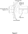
- Figure 2 illustrates a group of array elements 201 used to form an active aperture. The group of array elements are excited using a pattern of delayed excitation signals 210 to produce ultrasound wavefronts 220 that are focused along an image line 222 perpendicular to the array. Additional image lines are obtained by shifting the active aperture across the array. A sub-aperture of elements steps across a much larger aperture, collecting the parallel A-scans needed to produce a 2-D image.
- a typical linear array will have a total aperture consisting of 256 elements, and use a sub-aperture of 64 elements with wavelength spacing ⁇ between the array elements 201.
- Figure 3 illustrates the second version of a linear array, the "phased array,” that has the ability to steer the ultrasound wavefronts 320.
- the elements 301 in the phased array are excited using a pattern of delayed excitation signals 310 that focuses and steers the ultrasound wavefronts 320. Consequently, the image line 322 is no longer perpendicular to the array. Additional image lines are obtained by changing the steering angle.
- a series of A-scans are collected. These A-scans are used to generate a sector format image.
- phased arrays can have a large field of view with a relatively small aperture.
- a phased array will use 128 elements with half-wavelength spacing between the array elements 301.
- phased arrays are similar to linear arrays.
- annular arrays such as the example shown in Figure 1(C)
- annular arrays are suitable for many topical applications in high-frequency imaging, due to their relatively large element sizes and low element counts, they do not have the ability to beam steer or translate the aperture electronically and therefore need to be mechanically scanned. This means that the fixed aperture needs to be relocated in space in order to generate the parallel "lines of sight” that make up a 2D image. This creates a larger “effective” aperture limiting the packaging size, image scan window, and frame rate.
- High-frequency linear phased array transducers can overcome many of the problems inherent to annular arrays. For example, since phased arrays require no aperture translation arrays that are 3 mm or less in total aperture can be manufactured.
- an ultrasound beamformer which generates the sequence of high voltage pulses required to excite the array and focus the transmitted energy; and the receive beamformer, which focuses the received signals.
- the operation of the transmit beamformer will be described with reference to Figure 4 .
- Figure 4 illustrates a geometrical arrangement of an array of elements 1 through n (in cross-section) that are each separated by a distance d, and a desired focal point, target 444, within an imaging medium.
- the lines connecting the transducer array elements 1 through n to the target 444 show the paths from each element to the target 444.
- the path length distances from each of the transducer elements 1 through n to the target 444 must be determined. Then the delay pattern to apply to signals to the transducer elements 1 through n that is required to focus the sound waves to the target 444 can be determined.
- Equation (1) l n is the distance from the nth transducer element to the desired (x,y) coordinate. If a constant speed of sound within the medium is assumed, the total time it takes a pulse to travel from the nth transducer element to the target is l n / c o , wherein c o is the assumed speed of sound within the medium.
- Equation (2) ⁇ ⁇ n corresponds to the excitation delay for element n. Because a transmit beamformer can only focus at one depth for each transmit event, the transmitted wave is allowed to disperse before subsequent transmit pulses are applied.
- the echo from a small object in the body will arrive back at different array elements at slightly different times.
- the echoes can be re-aligned so that they will add coherently.
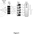
- a flow diagram of receive beamforming is shown schematically in Figure 5 .
- the transducers (array elements 501) receive the reflected wave 505 and the signals produced are delayed in a phased pattern using delay devices 550 to create constructive interference upon summation at adder 555.
- the receive beamforming process is similar to transmit focusing with a difference: in transmit focusing, pulses can only be focused to one depth in the tissue at a time, whereas in receive beamforming it is possible to dynamically change the delay pattern applied to the echoes as they are received.
- receive beamforming allows one to approximate the radiation pattern of a geometrically shaped transducer whose geometric focus is sweeping forward at the speed of sound.
- the delay pattern for the transducer elements in the array 501 is related to the time of flight between the element and the target.
- Phased array transducers can provide a large field of view with a small aperture.
- a small pitch ( ⁇ 0.5 ⁇ ) is conventionally required for phased array transducers in order to avoid large grating lobes.
- the present disclosure provides a novel method for ultrasound imaging in which splitting the transmit aperture into K sub-apertures generates broader band grating lobe echoes.
- a suitable signal processing method such as for example, the previously described SCF weighting coefficients, grating lobes can be significantly suppressed over a conventional transmit beamforming technique with large pitch arrays.
- an expression for the optimal aperture splitting location can be derived that will produce equally short transmit pulses in the grating lobe region for the different sub-apertures.
- Splitting the aperture into equal-width sub-apertures closely approximates the optimal splitting locations for most f-numbers and grating lobe angles.
- the use of a larger number of sub-apertures (K) can increase the amount of grating lobe suppression for different pitches and steering angles. By increasing the steering angle, greater values of K are required for acceptable grating lobe suppression. Therefore, the number of split apertures (K) should be chosen based on the steering angle and desired image contrast (grating lobe level) for the individual application.
- the present methods enable high-frequency phased array transducers to be developed with larger element-to-element pitch, which simplifies device fabrication significantly.
- High-frequency ultrasound imaging i.e., >20 MHz
- the current commercially available systems are mostly limited to intravascular and small animal imaging applications.
- the relatively slow expansion into new clinical applications of high-frequency ultrasound can mostly be attributed to the difficulties in developing array-based transducers and beamformers operating at these frequencies.
- high-frequency ultrasound imaging systems have been based on single-element transducers, which introduce a trade-off between lateral resolution and depth-of-field. Mechanical aperture translation is also needed in this case to capture a full 2D image.
- high-frequency annular arrays have been shown to provide large depth-of-field and high-quality images, they also require mechanical spatial translation, which can limit the frame rate and packaging size.
- the development of high-frequency linear array transducers has proven to overcome limitations in frame-rate previously introduced by the mechanical translation, however, the field-of-view and packaging size is limited to the size of the full aperture since linear arrays can only focus the ultrasound beam perpendicular to the array and do not have the ability to beam-steer.
- the development of a high-frequency curvilinear array has recently been reported ( Hu et al., Proc IEEE Ultrason Symp (2009 )). Although arrays such as these are indeed promising, a more efficient method of overcoming the tradeoff between field of view and aperture size can be achieved with a phased array transducer.
- Phased array transducers have the ability to beam-steer and do not need to electronically translate a sub-aperture in order to generate parallel A-scan lines.
- developing high-frequency phased array transducers has proven to be extremely difficult due to the difficulties in fabrication.
- the element-to-element pitch needs to be significantly reduced in order to avoid the introduction of grating lobes ( Cobbold, Foundations of biomedical ultrasound, 437-450 (2007 )).
- the element pitch needs to be reduced to 15 microns ( Ziomek, Fundamentals of acoustic field theory and space-time signal processing, 528-532 (1955 )), which is beyond most current fabrication capabilities.
- the processing method comprises weighting the samples by a calculated phase coherence factor, which can comprise SCF.
- One suitable signal processing method focuses primarily on manipulation of the array structure by removing the periodic pattern of the elements ( Rew et al., Electronics letter, 19(19):1729-1731 (1993 ); Govicov et al., IEEE Trans UFFC, 44(5):1010-1017 (1997 ); Wang et al., IEEE Trans Antennas and Propagation, 56(6) (2008 )).
- some elements are removed randomly until an under-sampled portion of the aperture remains, resulting in a "sparse array.”
- SNR signal-to-noise ratio
- the signal processing method can comprise a method for suppressing grating lobes that focuses on processing the echoes received by each element to suppress grating lobes.
- a weighting factor (between 0-1) is calculated based on a specific characteristic of echoes such as time-shift (cross-correlation ( Ustuner et al., U.S. Pat. No. 7,207,942 B2 (2007 ))) or the receiving direction of the echoes (FFT ( Li et al., IEEE Trans UFFC, 50(2):128-141 (2003 ))).
- the echoes are multiplied by the computed weighting factors and added to generate one line of the image.
- the signal processing can comprise a low-computational power method called "phase coherence imaging" for grating lobe suppression in large pitch arrays ( Camacho et al., IEEE Trans UFFC, 56(5):958-974 (2009 )).
- phase coherence imaging for grating lobe suppression in large pitch arrays
- the phase of delayed echoes received by each element is detected and then a weighting factor is defined based on the standard deviation of the phases at each time point. At the focal point, all of the element echoes will be in phase, so the standard deviation of their phases is close to zero, which results in a weighting factor close to one.
- the phases of the echoes are not always perfectly in phase, so the standard deviation of them in certain cases is greater than zero, resulting in a lower weighting factor.
- This method is mostly effective for synthetic aperture beamforming where the received grating lobe echoes are broadband. Essentially, after the transmit beamforming delays are reconstructed along with the receive beamformed A-scans, time domain points that are similar to the main lobe are either zero or random in phase over a large number of the elements. This creates a spread in the standard deviation of phases and therefore the broad bandwidth of the received echoes is the primary reason that the standard deviation of the phases is non-zero.
- the present disclosure provides novel methods for generalizing the phase coherence imaging method for suppressing grating lobes of phased array transducers when using transmit beamforming, where long narrowband grating lobe echoes are inevitable.
- the present disclosure relates generally to systems and methods for effectively reducing the temporal length of transmit grating lobe signal in received ultrasound echoes.
- the benefits of grating lobe suppression through signal processing are significantly improved by decreasing the time-domain signal of the grating lobe signal prior to signal processing.
- phased arrays with element pitches much larger than one-half of the ultrasound signal wavelength are possible. Therefore, the fabrication of high-frequency phased arrays is significantly simplified, and the number of elements required in 2D arrays is reduced.
- phase coherence imaging is calculating sign coherence factor (SCF) as the weighting factor.
- SCF sign coherence factor
- the sign bit of received echoes by each element ( b i ) at each time point is considered ( Camacho et al., IEEE Trans UFFC, 56(5):958-974 (2009 )).
- the present method makes possible the performance of high-frequency ultrasound imaging at greater image resolution.
- the method can be performed at frequencies of 20 MHz, 30 MHz, 40 MHz, or 50 MHz.
- the present methods are also applicable to low frequency ultrasound, such as at frequencies below 20 MHz.
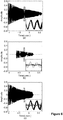
- Figure 6(A) shows an example of the individually received echoes from the grating lobe region resulting from transmit beamforming.
- the signals are for a 64 element phased array with an element pitch of 1.25 ⁇ steering at an angle of 25 degrees and focusing to f/2.
- the pulse echoes were simulated using the two-way impulse response method ( San Emeterio et al., J Acoust Soc AM, 92(2):651-662 (1992 )).
- the sum of the one-way transmit pulses in the grating lobe region is calculated and then used as the point source for the received echoes.
- the bandwidth of the two-way pulse echo in the main lobe region however is approximately 50%.
- Figure 6(A) clearly shows how the overlapping echoes from the grating lobe region are stretched out in the time domain. Because they are virtually all in phase over a temporal window similar to the main lobe, a large weighting factor results. This prevents SCF from effectively suppressing grating lobes when transmit beamforming is used.
- the SCF method can, however, effectively suppress grating lobes when synthetic aperture transmit beamforming is used.
- the main difference is that for synthetic aperture, only one element is pulsed at a time which results in broadband echoes returning to the array, even from the grating lobe region. After the receive beamforming delays are inserted, these broadband echoes have very small overlap in the time domain resulting a large sign-bit standard deviation since many of the signals are zero (random phase) at any given moment in time. This produces a very low SCF weighting coefficient.
- Figure 6(B) shows an example of the received grating lobe echoes from a 64 element, 1.25 ⁇ pitch phased array steering to 25 degrees when pulsed with a single defocused element (element 32). In this case, it can clearly be seen that the echoes are predominately not in phase in the same temporal region as the main lobe signal. In fact, the received signals are so broad band that most are zero (random phase).
- synthetic aperture beamforming has significant disadvantages because many transmit events are required before the signals are beamformed. Therefore, the pre-beamformed signals are susceptible to phase distortions from small tissue movements during the relatively long pulsing sequence.
- High-frequency arrays are particularly sensitive to small tissue movements since the wavelengths are extremely short and therefore a small amount of tissue motion results in a large change in the echo phase.
- Transmit beamforming avoids these phase distortions because long pulsing sequences between beamforming are not required.
- the methods of the present disclosure advantageously shorten the time-domain of grating lobes without requiring the use of synthetic aperture beamforming.
- the number of sub-apertures (K) can be any value such that the transmit aperture is capable of producing a focused beam.
- K is an integer between 2 and 16. In further aspects, K is between 2 and 10. In yet further aspects, K is 2.
- any suitable element-to-element pitch can be used according to the present methods.
- the element-to-element pitch is greater than 0.5 ⁇ . In further aspects, the element-to-element pitch is 0.5 ⁇ . In certain aspects the element-to-element pitch is 0.75 ⁇ . In certain aspects the element-to-element pitch is 1 ⁇ . In certain aspects the element-to-element pitch is 1.25 ⁇ .
- the steering angle can be from 1 to 45 degrees. In certain aspects, the steering angle is 10 degrees. In further aspects, the steering angle is 15 degrees. In further aspects, the steering angle is 20 degrees. In further aspects, the steering angle is 25 degrees. In further aspects, the steering angle is 35 degrees. In further aspects, the steering angle is 40 degrees. In further aspects, the steering angle is 45 degrees.
- any suitable array size (N) can be used, for example and without limitation, the array size (N) can be between 16 and 512.
- the methods of the present disclosure use transmit focusing along different lines of sight.
- N/K elements are pulsed with transmit focusing delays and all N elements participate in the receive aperture ( Figure 7(B) ).
- the SCF is calculated based on the time-shifted echoes and is used to weight the beamformed signal.
- all weighted echoes are added together to generate one line in the image.
- the grating lobe signal is shorter due to the reduced difference in distance between the closest and furthest elements in the transmit aperture. This reduction in overlap for the grating lobe echoes results in a much lower SCF.
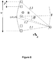
- the optimal transmit apertures are determined in order to achieve equally short temporal transmit pulses between sub-apertures in the grating lobe region.
- the optimal position occurs when the difference in distance between the closest and furthest elements in each sub-aperture are equal.
- L1, L2, and L3 are the distances between the grating lobe point (G) and the points on the virtual curved aperture. In order to have transmit pulses with the same length in the time domain for both splits, the equality of distances defined in (3) should be satisfied.
- L2 x 0 R sin ⁇ ⁇ x 0 2 + R cos ⁇ ⁇ R ⁇ R 2 + w 2 2 ⁇ x 0 2 2 and L1 and L3 are simply L 2 w 2 and L 2 ⁇ w 2 respectively.
- the following derivation is based on the assumption that R > > w 2 which is a reasonable assumption at f-numbers greater than 2.
- Equation (9) By squaring the right side of Equation (5), and again using the Taylor approximation in Equation (9), we obtain the expression: R sin ⁇ ⁇ x 0 2 + R cos ⁇ ⁇ R ⁇ R 2 + w 2 2 ⁇ x 0 2 2 ⁇ 1 ⁇ cos ⁇ x 2 0 ⁇ 2 R sin ⁇ x 0 + cos ⁇ w 2 4 + R 2
- Equation (8) and Equation (10) therefore results in 1 ⁇ co
- x 0 F ⁇ sin ⁇ ⁇ ⁇ F 2 sin 2 ⁇ ⁇ 1 ⁇ cos ⁇ cos ⁇ ⁇ 4 ⁇ F 2 cos 2 ⁇ 4 F 2 ⁇ 1 1 ⁇ cos ⁇ Np
- x o is a function of ( N,F,p ). Generally, however the expression for x o approaches zero at very large and very small grating lobe angles (i.e., the aperture is split at the central element). Intuitively, one can visualize a pulse arriving at the virtual curved aperture either from 90 degrees or from the main axis.
- Equation (12) was based on an approximation that is valid for f-numbers greater than approximately 2. In various aspects, f-numbers greater than 1 are suitable for use with the present methods. In certain aspects, a focal dept of f/2 can be used.
- the grating lobe signal can be suppressed by between 20 dB and 60 dB. In certain aspects, the grating lobe signal can be suppressed by 20 dB. In certain aspects, the grating lobe signal can be suppressed by 40 dB. In certain aspects, the grating lobe signal can be suppressed by 60 dB.
- the present disclosure provides a system for high-frequency ultrasound imaging using a split transmit aperture, the system comprising: an imaging array comprising a phased array of N transmit elements, the transmit elements divisible into K sub-apertures, each sub-aperture having N/K transmit elements; a transmit beamformer coupled to the imaging array, wherein the transmit beamformer is configured to apply energy selectively to the elements of each of the sub-apertures to focus a transmit signal from the sub-aperture towards a target; a receive beamformer coupled to the imaging array, wherein the receive beamformer is configured to sample a signal received by the imaging array at each of the N elements thereof; and processing circuitry configured to receive the sampled signal and compute an imaged based thereon.
- a computer controls the transmit beamformer.
- the transmit signals can comprise pulsed signals.
- the transmitted signals reflect off of tissue structures (or target areas) and are received by the elements in the imaging array. These signals received at the imaging array can be directed through amplifiers that are connected between the elements of the imaging array. The digital data is transferred back to the computer for image processing.
- the number of sub-apertures (K) in the system can be any value such that the transmit aperture is capable of producing a focused beam.
- K is an integer between 2 and 16. In further aspects, K is between 2 and 10. In yet further aspects, K is 2.
- any suitable element-to-element pitch can be used according to the present systems.
- the element-to-element pitch is greater than 0.5 ⁇ . In further aspects, the element-to-element pitch is 0.5 ⁇ . In certain aspects the element-to-element pitch is 0.75 ⁇ . In certain aspects the element-to-element pitch is 1 ⁇ . In certain aspects the element-to-element pitch is 1.25 ⁇ .
- the steering angle can be from 1 to 45 degrees. In certain aspects, the steering angle is 10 degrees. In further aspects, the steering angle is 15 degrees. In further aspects, the steering angle is 20 degrees. In further aspects, the steering angle is 25 degrees. In further aspects, the steering angle is 35 degrees. In further aspects, the steering angle is 40 degrees. In further aspects, the steering angle is 45 degrees.
- any suitable array size (N) can be used, for example and without limitation, the array size (N) can be between 16 and 512.
- the presently described methods can be used for any suitable application, such as for example endoscopy, which includes without limitation, laproscopic, itra-cardiac, and surgical guidance imaging, and the like.
- endoscopy which includes without limitation, laproscopic, itra-cardiac, and surgical guidance imaging, and the like.
- the high-frequency ultrasound imaging system described herein can improve diagnostics, interventions, and therapeutic monitoring of a variety of disorders.
- This new diagnostic imaging approach can improve the objectivity and quality of diagnosis in this field of medicine, allowing physicians to apply more precisely targeted interventions.
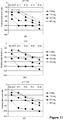
- SCF method for grating lobe suppression is dependent on the temporal length of the transmit pulse in the grating lobe region. The shorter the transmit pulse, the more effective the SCF method is for grating lobe suppression.
- the grating lobe suppression increases by increasing the number of split-apertures (K).
- K the number of split-apertures
- K 1 (SCF-weighting with no splitting)
- K 1 (SCF-weighting with no splitting)
- An alternative technique that could potentially avoid the need to use multiple transmit pulses per A-scan line is to send out a broad defocused "probing pulse" from the entire aperture in order to generate a map of SCF values for all space.
- beamforming delays corresponding to a virtual point source behind the array is required ( Lockwood et al., IEEE Trans UFFC, 45(4):980-988 (1998 )).
- the echoes that are received from all points in space are now very broad band (short) and after receive beamforming delays are inserted along different A-scan lines, echoes from the grating lobe regions will have low phase coherence and corresponding SCF weighting factors.
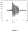
- Figures 12 and 13 show experimentally measured grating lobe transmit signals when the full 64 element aperture is active and focused off to 25 degrees at f/2 ( Figure 12 ) and when half of the aperture is active and focused off to 25 degrees at f/2 ( Figure 13 ).
- the measurements were obtained using a 64 element 50 MHz phased array with 1.25 ⁇ element pitch.
- a comparison of Figures 12 and 13 demonstrates that the length of the grating lobe signal is reduced significantly when only half the aperture is used for transmit.
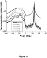
- Figure 14 shows experimentally measured radiation patterns from a 50 micron wire phantom located at 25 degrees and f/2 when the beam is swept from +35 degrees to - 35 degrees.
- the measurements were obtained using a 64 element 50 MHz phased array with 1.25 ⁇ element pitch.
- split-transmit apertures are effective in grating lobe suppression with SCF weighting factors. Specifically, the level of grating lobes in this case are suppressed more than 20dB when the aperture is split in two. The grating lobe levels could be suppressed even further upon more aperture splits.
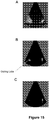
- Figure 15 shows images generated with a 64 element 50 MHz phased array with 1.25 ⁇ spacing.
- the image is of a 50-micron wire phantom located at f/2.5.
- the image depth ranges from 1 mm to 8 mm and the steering angle ranges from +35 degrees to -35 degrees. All images are displayed with a dynamic range of 60 dB.
- the use of a split transmit aperture dramatically improves image quality, and when used in conjunction with a processing method such as SCF, results in significant suppression of grating lobes.
Landscapes
- Engineering & Computer Science (AREA)
- Physics & Mathematics (AREA)
- Radar, Positioning & Navigation (AREA)
- Remote Sensing (AREA)
- Acoustics & Sound (AREA)
- Health & Medical Sciences (AREA)
- Life Sciences & Earth Sciences (AREA)
- Computer Networks & Wireless Communication (AREA)
- General Physics & Mathematics (AREA)
- Pathology (AREA)
- Surgery (AREA)
- Nuclear Medicine, Radiotherapy & Molecular Imaging (AREA)
- Veterinary Medicine (AREA)
- Radiology & Medical Imaging (AREA)
- Biomedical Technology (AREA)
- Heart & Thoracic Surgery (AREA)
- Medical Informatics (AREA)
- Molecular Biology (AREA)
- Biophysics (AREA)
- Animal Behavior & Ethology (AREA)
- General Health & Medical Sciences (AREA)
- Public Health (AREA)
- Computer Vision & Pattern Recognition (AREA)
- Multimedia (AREA)
- Gynecology & Obstetrics (AREA)
- Ultra Sonic Daignosis Equipment (AREA)
Applications Claiming Priority (2)
| Application Number | Priority Date | Filing Date | Title |
|---|---|---|---|
| US30224210P | 2010-02-08 | 2010-02-08 | |
| PCT/IB2011/000430 WO2011095896A1 (en) | 2010-02-08 | 2011-02-08 | Ultrasound imaging system using beamforming techniques for phase coherence grating lobe suppression |
Publications (3)
| Publication Number | Publication Date |
|---|---|
| EP2534502A1 EP2534502A1 (en) | 2012-12-19 |
| EP2534502A4 EP2534502A4 (en) | 2017-04-12 |
| EP2534502B1 true EP2534502B1 (en) | 2020-04-29 |
Family
ID=44355020
Family Applications (1)
| Application Number | Title | Priority Date | Filing Date |
|---|---|---|---|
| EP11739471.8A Active EP2534502B1 (en) | 2010-02-08 | 2011-02-08 | Ultrasound imaging system using beamforming techniques for phase coherence grating lobe suppression |
Country Status (5)
| Country | Link |
|---|---|
| US (2) | US9033888B2 (enExample) |
| EP (1) | EP2534502B1 (enExample) |
| JP (2) | JP5907895B2 (enExample) |
| CA (1) | CA2789129C (enExample) |
| WO (1) | WO2011095896A1 (enExample) |
Families Citing this family (42)
| Publication number | Priority date | Publication date | Assignee | Title |
|---|---|---|---|---|
| EP2442132B1 (en) * | 2010-10-13 | 2014-11-26 | Hitachi Aloka Medical, Ltd. | Ultrasonic diagnosis apparatus |
| JP5829680B2 (ja) * | 2011-04-20 | 2015-12-09 | 株式会社日立メディコ | 超音波撮像装置 |
| EP2574956A1 (en) * | 2011-09-30 | 2013-04-03 | GE Inspection Technologies Ltd | Ultrasound imaging system and method with side lobe suppression via coherency factor weighting |
| CN103565469B (zh) * | 2012-08-01 | 2015-05-20 | 华中科技大学 | 一种提高二维阵列实时超声体成像质量的方法 |
| DE102013201975A1 (de) | 2013-02-07 | 2014-08-07 | Siemens Aktiengesellschaft | Verfahren und Vorrichtung zur Verbesserung der SAFT-Analyse bei unregelmäßiger Messung |
| DE102013004924B4 (de) * | 2013-03-22 | 2018-05-03 | GE Sensing & lnspection Technologies GmbH | Bildgebungssystem und -verfahren |
| KR102191967B1 (ko) | 2013-10-07 | 2020-12-16 | 삼성전자주식회사 | 대상체의 탄성 특성을 획득하는 방법 및 장치 |
| EP3108265A1 (en) | 2014-02-18 | 2016-12-28 | Sound Technology Inc. | Acoustic signal phase rotation processor |
| CN107205730B (zh) * | 2015-02-12 | 2020-02-07 | 株式会社日立制作所 | 超声波成像装置、发送间权重调整方法和超声波成像方法 |
| WO2017035838A1 (zh) | 2015-09-06 | 2017-03-09 | 深圳迈瑞生物医疗电子股份有限公司 | 超声灰阶成像系统及方法 |
| US10993701B2 (en) * | 2015-09-16 | 2021-05-04 | Hitachi, Ltd. | Ultrasonic imaging device |
| CN105411626B (zh) * | 2015-12-24 | 2018-05-25 | 华中科技大学 | 一种基于超声ct的合成孔径成像方法及系统 |
| CA3008520A1 (en) * | 2016-02-23 | 2017-08-31 | Sunnybrook Research Institute | Phased array transducer with coupling layer for suppression of grating lobes |
| US11744468B2 (en) * | 2016-04-27 | 2023-09-05 | The Johns Hopkins University | General B-mode surface imaging |
| US10700444B2 (en) | 2016-07-06 | 2020-06-30 | Industrial Technology Research Institute | Multi-beam phased antenna structure and controlling method thereof |
| JP6393442B2 (ja) * | 2016-09-23 | 2018-09-19 | Jfeスチール株式会社 | 超音波源の方位標定装置及び重ね合わせ画像の解析方法 |
| FR3063003A1 (fr) * | 2017-02-22 | 2018-08-24 | Quantel Medical | Procede d'echographie oculaire a transducteurs annulaires |
| JP6469746B2 (ja) * | 2017-03-23 | 2019-02-13 | キヤノンメディカルシステムズ株式会社 | 超音波診断装置及び制御プログラム |
| US10120261B2 (en) | 2017-04-05 | 2018-11-06 | Analog Devices, Inc. | Array of sub-aperture refractive elements for steering a light beam |
| CN212623066U (zh) | 2017-06-02 | 2021-02-26 | 菲力尔系统公司 | 测距系统 |
| DE112018003501T5 (de) * | 2017-07-09 | 2020-04-23 | The Board Of Trustees Of The Leland Stanford Junior University | Ultraschallbildgebung mit spektraler compoundierung zur speckle-reduzierung |
| US10133083B1 (en) * | 2017-08-16 | 2018-11-20 | Analog Devices, Inc. | Hybrid beamsteerer for steering a light beam with both sub-aperture and full-aperture beam steering portions |
| US10605907B2 (en) * | 2017-11-15 | 2020-03-31 | Cognitive Systems Corp. | Motion detection by a central controller using beamforming dynamic information |
| US10852411B2 (en) | 2017-12-06 | 2020-12-01 | Cognitive Systems Corp. | Motion detection and localization based on bi-directional channel sounding |
| US10976579B2 (en) | 2018-08-09 | 2021-04-13 | Analog Devices, Inc. | Liquid crystal waveguide with active incoupling |
| US10684531B1 (en) | 2019-02-22 | 2020-06-16 | Analog Devices, Inc. | Hybrid optical beam steering |
| US10798529B1 (en) | 2019-04-30 | 2020-10-06 | Cognitive Systems Corp. | Controlling wireless connections in wireless sensing systems |
| US10743143B1 (en) | 2019-05-15 | 2020-08-11 | Cognitive Systems Corp. | Determining a motion zone for a location of motion detected by wireless signals |
| US10924889B1 (en) | 2019-09-30 | 2021-02-16 | Cognitive Systems Corp. | Detecting a location of motion using wireless signals and differences between topologies of wireless connectivity |
| US11018734B1 (en) | 2019-10-31 | 2021-05-25 | Cognitive Systems Corp. | Eliciting MIMO transmissions from wireless communication devices |
| US11570712B2 (en) | 2019-10-31 | 2023-01-31 | Cognitive Systems Corp. | Varying a rate of eliciting MIMO transmissions from wireless communication devices |
| EP4052065B1 (en) | 2019-10-31 | 2025-06-11 | Cognitive Systems Corp. | Using mimo training fields for motion detection |
| US11715453B2 (en) * | 2019-12-25 | 2023-08-01 | Ultraleap Limited | Acoustic transducer structures |
| US10928503B1 (en) | 2020-03-03 | 2021-02-23 | Cognitive Systems Corp. | Using over-the-air signals for passive motion detection |
| US12019143B2 (en) | 2020-03-03 | 2024-06-25 | Cognitive Systems Corp. | Using high-efficiency PHY frames for motion detection |
| WO2022040817A1 (en) | 2020-08-31 | 2022-03-03 | Cognitive Systems Corp. | Controlling motion topology in a standardized wireless communication network |
| US11070399B1 (en) | 2020-11-30 | 2021-07-20 | Cognitive Systems Corp. | Filtering channel responses for motion detection |
| US12376828B2 (en) * | 2021-04-19 | 2025-08-05 | Bfly Operations, Inc. | Methods and systems for coherence imaging in obtaining ultrasound images |
| US12390189B2 (en) * | 2021-04-21 | 2025-08-19 | GE Precision Healthcare LLC | Methods and systems for ultrasound imaging with pulse-inversion scheme and retrospective transmit techniques |
| CN113687364B (zh) * | 2021-07-13 | 2024-03-19 | 中国船舶重工集团公司第七一五研究所 | 一种三维成像声纳图像假底的抑制方法 |
| CN116058869A (zh) * | 2023-01-09 | 2023-05-05 | 飞依诺科技股份有限公司 | 超声设备的合成孔径方法及装置 |
| CN117503203B (zh) * | 2024-01-03 | 2024-03-22 | 之江实验室 | 一种用于超声环阵成像的相位畸变校正方法和系统 |
Family Cites Families (40)
| Publication number | Priority date | Publication date | Assignee | Title |
|---|---|---|---|---|
| US3877031A (en) | 1973-06-29 | 1975-04-08 | Unied States Of America As Rep | Method and apparatus for suppressing grating lobes in an electronically scanned antenna array |
| US4228436A (en) | 1978-04-03 | 1980-10-14 | Hughes Aircraft Company | Limited scan phased array system |
| AU531239B2 (en) | 1978-06-15 | 1983-08-18 | Plessey Overseas Ltd. | Directional arrays |
| US4542653A (en) | 1983-11-21 | 1985-09-24 | Advanced Technology Laboratories, Inc. | Apparatus and method for beamforming in an ultrasonic transducer array |
| JP2501350B2 (ja) * | 1988-12-16 | 1996-05-29 | アロカ 株式会社 | 超音波診断装置 |
| JPH02209135A (ja) * | 1989-02-09 | 1990-08-20 | Yokogawa Medical Syst Ltd | 超音波送受信装置 |
| US5111695A (en) * | 1990-07-11 | 1992-05-12 | General Electric Company | Dynamic phase focus for coherent imaging beam formation |
| JPH05277117A (ja) | 1992-04-02 | 1993-10-26 | Yokogawa Medical Syst Ltd | 超音波診断方法および装置 |
| US5322068A (en) * | 1993-05-21 | 1994-06-21 | Hewlett-Packard Company | Method and apparatus for dynamically steering ultrasonic phased arrays |
| US5349262A (en) | 1994-02-22 | 1994-09-20 | Hewlett-Packard Company | Phased array ultrasound imaging system with dynamic elevation focusing |
| JPH10127633A (ja) * | 1996-11-06 | 1998-05-19 | Aloka Co Ltd | 超音波診断装置 |
| US6689063B1 (en) | 1999-05-10 | 2004-02-10 | B-K Medical A/S | Method and apparatus for acquiring images by recursive ultrasound images |
| US7399279B2 (en) | 1999-05-28 | 2008-07-15 | Physiosonics, Inc | Transmitter patterns for multi beam reception |
| US7534209B2 (en) | 2000-05-26 | 2009-05-19 | Physiosonics, Inc. | Device and method for mapping and tracking blood flow and determining parameters of blood flow |
| JP2003235839A (ja) | 2002-02-18 | 2003-08-26 | Matsushita Electric Ind Co Ltd | 超音波診断装置 |
| JP2004113693A (ja) | 2002-09-30 | 2004-04-15 | Fuji Photo Film Co Ltd | 超音波撮像装置及び超音波撮像方法 |
| US7207942B2 (en) | 2003-07-25 | 2007-04-24 | Siemens Medical Solutions Usa, Inc. | Adaptive grating lobe suppression in ultrasound imaging |
| US7972271B2 (en) | 2003-10-28 | 2011-07-05 | The Board Of Trustees Of The Leland Stanford Junior University | Apparatus and method for phased subarray imaging |
| US7527592B2 (en) | 2003-11-21 | 2009-05-05 | General Electric Company | Ultrasound probe sub-aperture processing |
| US7833163B2 (en) * | 2003-12-10 | 2010-11-16 | Siemens Medical Solutions Usa, Inc. | Steering angle varied pattern for ultrasound imaging with a two-dimensional array |
| US7744532B2 (en) * | 2004-03-31 | 2010-06-29 | Siemens Medical Solutions Usa, Inc. | Coherence factor adaptive ultrasound imaging methods and systems |
| US7914454B2 (en) * | 2004-06-25 | 2011-03-29 | Wilk Ultrasound Of Canada, Inc. | Real-time 3D ultrasonic imaging apparatus and method |
| US20060173313A1 (en) | 2005-01-27 | 2006-08-03 | Siemens Medical Solutions Usa, Inc. | Coherence factor adaptive ultrasound imaging |
| US7081851B1 (en) | 2005-02-10 | 2006-07-25 | Raytheon Company | Overlapping subarray architecture |
| CH698594B1 (de) | 2005-08-03 | 2009-09-15 | King Faisal Specialist Hospita | Vorrichtung für die operative Verbindung von Hohlorganen, insbesondere von Blutgefässen. |
| WO2007027703A2 (en) * | 2005-08-29 | 2007-03-08 | University Of Toledo | System for extended high frame rate imaging with limited-diffraction beams |
| US8465431B2 (en) * | 2005-12-07 | 2013-06-18 | Siemens Medical Solutions Usa, Inc. | Multi-dimensional CMUT array with integrated beamformation |
| US7874991B2 (en) | 2006-06-23 | 2011-01-25 | Teratech Corporation | Ultrasound 3D imaging system |
| CN101190133B (zh) * | 2006-11-28 | 2011-05-18 | 深圳迈瑞生物医疗电子股份有限公司 | 超声波诊断系统中宽波束的发射方法和装置 |
| US7701380B2 (en) | 2007-03-07 | 2010-04-20 | Chirp Corporation | Beam phase modulation for improved synthetic aperture detection and estimation |
| US8096951B2 (en) * | 2007-06-28 | 2012-01-17 | General Electric Company | Transmit beamforming in 3-dimensional ultrasound |
| RU2491685C2 (ru) | 2007-07-20 | 2013-08-27 | Астриум Лимитед | Система для упрощения обработки реконфигурируемой диаграммообразующей схемы в фазированной антенной решетке для телекоммуникационного спутника |
| US8254654B2 (en) * | 2007-10-31 | 2012-08-28 | University Of Southern California | Sidelobe suppression in ultrasound imaging using dual apodization with cross-correlation |
| ES2332637B1 (es) * | 2008-08-08 | 2010-12-01 | Consejo Superior De Investigacion Cientifica (Csic) | Procedimiento y aparato para la correccion de imagenes ultrasonicas por analisis de fase. |
| US10080544B2 (en) | 2008-09-15 | 2018-09-25 | Teratech Corporation | Ultrasound 3D imaging system |
| US8416643B2 (en) | 2009-03-24 | 2013-04-09 | Texas Instruments Incorporated | Receive beamformer for ultrasound having delay value sorting |
| JP5396242B2 (ja) * | 2009-11-11 | 2014-01-22 | 日立アロカメディカル株式会社 | 超音波診断装置 |
| JP5575554B2 (ja) | 2010-06-23 | 2014-08-20 | 株式会社東芝 | 超音波診断装置 |
| US8545406B2 (en) | 2010-12-06 | 2013-10-01 | Texas Instruments Incorporated | Dynamic aperture control and normalization for apodization in beamforming |
| KR101253608B1 (ko) | 2010-12-27 | 2013-04-11 | 서강대학교산학협력단 | 합성영상을 생성하는 방법 및 이를 이용한 초음파 영상 장치 |
-
2011
- 2011-02-08 JP JP2012551706A patent/JP5907895B2/ja active Active
- 2011-02-08 US US13/574,844 patent/US9033888B2/en active Active
- 2011-02-08 EP EP11739471.8A patent/EP2534502B1/en active Active
- 2011-02-08 CA CA2789129A patent/CA2789129C/en active Active
- 2011-02-08 WO PCT/IB2011/000430 patent/WO2011095896A1/en not_active Ceased
-
2015
- 2015-05-14 US US14/712,698 patent/US9730676B2/en active Active
- 2015-12-18 JP JP2015247170A patent/JP6257096B2/ja active Active
Non-Patent Citations (1)
| Title |
|---|
| J.A. JOHNSON ET AL: "Coherent-array imaging using phased subarrays. Part I: basic principles", IEEE TRANSACTIONS ON ULTRASONICS, FERROELECTRICS AND FREQUENCY CONTROL, vol. 52, no. 1, 1 January 2005 (2005-01-01), pages 37 - 50, XP055000971, ISSN: 0885-3010, DOI: 10.1109/TUFFC.2005.1397349 * |
Also Published As
| Publication number | Publication date |
|---|---|
| EP2534502A4 (en) | 2017-04-12 |
| JP2013518655A (ja) | 2013-05-23 |
| JP6257096B2 (ja) | 2018-01-10 |
| JP5907895B2 (ja) | 2016-04-26 |
| US9033888B2 (en) | 2015-05-19 |
| CA2789129A1 (en) | 2011-08-11 |
| WO2011095896A1 (en) | 2011-08-11 |
| US20150366542A1 (en) | 2015-12-24 |
| EP2534502A1 (en) | 2012-12-19 |
| US9730676B2 (en) | 2017-08-15 |
| CA2789129C (en) | 2017-08-22 |
| US20120296215A1 (en) | 2012-11-22 |
| JP2016034599A (ja) | 2016-03-17 |
Similar Documents
| Publication | Publication Date | Title |
|---|---|---|
| EP2534502B1 (en) | Ultrasound imaging system using beamforming techniques for phase coherence grating lobe suppression | |
| US6309356B1 (en) | Method and apparatus for forming medical ultrasound images | |
| US6551246B1 (en) | Method and apparatus for forming medical ultrasound images | |
| US6685641B2 (en) | Plane wave scanning reception and receiver | |
| Bendjador et al. | The SVD beamformer: Physical principles and application to ultrafast adaptive ultrasound | |
| US8672846B2 (en) | Continuous transmit focusing method and apparatus for ultrasound imaging system | |
| Matrone et al. | The delay multiply and sum beamforming algorithm in ultrasound B-mode medical imaging | |
| US7957609B2 (en) | System for extended high frame rate imaging with limited-diffraction beams | |
| EP1004894B1 (en) | Method and apparatus for high-frame-rate high-resolution ultrasonic image data acquisition | |
| US20050148874A1 (en) | Ultrasonic imaging aberration correction with microbeamforming | |
| EP3126872B1 (en) | System and method for acoustic imaging with coherent compounding using intercostal spaces | |
| US6527720B1 (en) | Medical ultrasonic imaging method and system for spatial compounding | |
| US20050101867A1 (en) | Apparatus and method for phased subarray imaging | |
| JP2002523203A (ja) | 高調波イメージングを用いて疎なアレイのサイドローブ性能を向上させる方法及び装置 | |
| Wang et al. | MVDR-based coherence weighting for high-frame-rate adaptive imaging | |
| JPH10295694A (ja) | 超音波イメージング・システムの作動方法 | |
| Lokesh et al. | Diverging beam transmit through limited aperture: A method to reduce ultrasound system complexity and yet obtain better image quality at higher frame rates | |
| Zhang et al. | Ultrafast ultrasound imaging using combined transmissions with cross-coherence-based reconstruction | |
| US6517489B1 (en) | Method and apparatus for forming medical ultrasound images | |
| Kim et al. | Efficient array beam forming by spatial filtering for ultrasound B-mode imaging | |
| You et al. | Pixel-oriented adaptive apodization for plane-wave imaging based on recovery of the complete dataset | |
| JP2004261572A (ja) | ハーモニックな信号及びハーモニックでない信号を用いた超音波画像収差補正 | |
| Torbatian et al. | A split-aperture transmit beamforming technique with phase coherence grating lobe suppression | |
| Nili et al. | Field of view and resolution improvement in coprime sparse synthetic aperture ultrasound imaging | |
| Lou et al. | Improved contrast for high frame rate imaging using coherent compounding combined with spatial matched filtering |
Legal Events
| Date | Code | Title | Description |
|---|---|---|---|
| PUAI | Public reference made under article 153(3) epc to a published international application that has entered the european phase |
Free format text: ORIGINAL CODE: 0009012 |
|
| 17P | Request for examination filed |
Effective date: 20120904 |
|
| AK | Designated contracting states |
Kind code of ref document: A1 Designated state(s): AL AT BE BG CH CY CZ DE DK EE ES FI FR GB GR HR HU IE IS IT LI LT LU LV MC MK MT NL NO PL PT RO RS SE SI SK SM TR |
|
| DAX | Request for extension of the european patent (deleted) | ||
| RIC1 | Information provided on ipc code assigned before grant |
Ipc: G01S 7/52 20060101ALI20161201BHEP Ipc: G01S 7/523 20060101ALN20161201BHEP Ipc: G01S 15/89 20060101AFI20161201BHEP Ipc: A61B 8/00 20060101ALI20161201BHEP Ipc: G10K 11/34 20060101ALI20161201BHEP |
|
| RA4 | Supplementary search report drawn up and despatched (corrected) |
Effective date: 20170310 |
|
| RIC1 | Information provided on ipc code assigned before grant |
Ipc: G01S 7/523 20060101ALN20170306BHEP Ipc: G10K 11/34 20060101ALI20170306BHEP Ipc: G01S 15/89 20060101AFI20170306BHEP Ipc: A61B 8/00 20060101ALI20170306BHEP Ipc: G01S 7/52 20060101ALI20170306BHEP |
|
| STAA | Information on the status of an ep patent application or granted ep patent |
Free format text: STATUS: EXAMINATION IS IN PROGRESS |
|
| 17Q | First examination report despatched |
Effective date: 20190301 |
|
| GRAP | Despatch of communication of intention to grant a patent |
Free format text: ORIGINAL CODE: EPIDOSNIGR1 |
|
| RIC1 | Information provided on ipc code assigned before grant |
Ipc: G01S 7/523 20060101ALN20191008BHEP Ipc: A61B 8/00 20060101ALI20191008BHEP Ipc: G01S 15/89 20060101AFI20191008BHEP Ipc: G10K 11/34 20060101ALI20191008BHEP Ipc: G01S 7/52 20060101ALI20191008BHEP |
|
| STAA | Information on the status of an ep patent application or granted ep patent |
Free format text: STATUS: GRANT OF PATENT IS INTENDED |
|
| INTG | Intention to grant announced |
Effective date: 20191114 |
|
| RIC1 | Information provided on ipc code assigned before grant |
Ipc: G10K 11/34 20060101ALI20191105BHEP Ipc: G01S 7/523 20060101ALN20191105BHEP Ipc: A61B 8/00 20060101ALI20191105BHEP Ipc: G01S 7/52 20060101ALI20191105BHEP Ipc: G01S 15/89 20060101AFI20191105BHEP |
|
| RIN1 | Information on inventor provided before grant (corrected) |
Inventor name: BANCE, MANOHAR Inventor name: ADAMSON, ROBERT Inventor name: TORBATIAN, ZAHRA Inventor name: BROWN, JEREMY |
|
| RIN1 | Information on inventor provided before grant (corrected) |
Inventor name: TORBATIAN, ZAHRA Inventor name: ADAMSON, ROBERT Inventor name: BROWN, JEREMY Inventor name: BANCE, MANOHAR |
|
| GRAS | Grant fee paid |
Free format text: ORIGINAL CODE: EPIDOSNIGR3 |
|
| RAP1 | Party data changed (applicant data changed or rights of an application transferred) |
Owner name: DALHOUSIE UNIVERSITY |
|
| GRAA | (expected) grant |
Free format text: ORIGINAL CODE: 0009210 |
|
| STAA | Information on the status of an ep patent application or granted ep patent |
Free format text: STATUS: THE PATENT HAS BEEN GRANTED |
|
| AK | Designated contracting states |
Kind code of ref document: B1 Designated state(s): AL AT BE BG CH CY CZ DE DK EE ES FI FR GB GR HR HU IE IS IT LI LT LU LV MC MK MT NL NO PL PT RO RS SE SI SK SM TR |
|
| REG | Reference to a national code |
Ref country code: GB Ref legal event code: FG4D |
|
| REG | Reference to a national code |
Ref country code: CH Ref legal event code: EP |
|
| REG | Reference to a national code |
Ref country code: AT Ref legal event code: REF Ref document number: 1264132 Country of ref document: AT Kind code of ref document: T Effective date: 20200515 |
|
| REG | Reference to a national code |
Ref country code: DE Ref legal event code: R096 Ref document number: 602011066520 Country of ref document: DE |
|
| REG | Reference to a national code |
Ref country code: IE Ref legal event code: FG4D |
|
| REG | Reference to a national code |
Ref country code: NL Ref legal event code: MP Effective date: 20200429 |
|
| REG | Reference to a national code |
Ref country code: LT Ref legal event code: MG4D |
|
| PG25 | Lapsed in a contracting state [announced via postgrant information from national office to epo] |
Ref country code: PT Free format text: LAPSE BECAUSE OF FAILURE TO SUBMIT A TRANSLATION OF THE DESCRIPTION OR TO PAY THE FEE WITHIN THE PRESCRIBED TIME-LIMIT Effective date: 20200831 Ref country code: NO Free format text: LAPSE BECAUSE OF FAILURE TO SUBMIT A TRANSLATION OF THE DESCRIPTION OR TO PAY THE FEE WITHIN THE PRESCRIBED TIME-LIMIT Effective date: 20200729 Ref country code: FI Free format text: LAPSE BECAUSE OF FAILURE TO SUBMIT A TRANSLATION OF THE DESCRIPTION OR TO PAY THE FEE WITHIN THE PRESCRIBED TIME-LIMIT Effective date: 20200429 Ref country code: IS Free format text: LAPSE BECAUSE OF FAILURE TO SUBMIT A TRANSLATION OF THE DESCRIPTION OR TO PAY THE FEE WITHIN THE PRESCRIBED TIME-LIMIT Effective date: 20200829 Ref country code: GR Free format text: LAPSE BECAUSE OF FAILURE TO SUBMIT A TRANSLATION OF THE DESCRIPTION OR TO PAY THE FEE WITHIN THE PRESCRIBED TIME-LIMIT Effective date: 20200730 Ref country code: LT Free format text: LAPSE BECAUSE OF FAILURE TO SUBMIT A TRANSLATION OF THE DESCRIPTION OR TO PAY THE FEE WITHIN THE PRESCRIBED TIME-LIMIT Effective date: 20200429 Ref country code: SE Free format text: LAPSE BECAUSE OF FAILURE TO SUBMIT A TRANSLATION OF THE DESCRIPTION OR TO PAY THE FEE WITHIN THE PRESCRIBED TIME-LIMIT Effective date: 20200429 |
|
| REG | Reference to a national code |
Ref country code: AT Ref legal event code: MK05 Ref document number: 1264132 Country of ref document: AT Kind code of ref document: T Effective date: 20200429 |
|
| PG25 | Lapsed in a contracting state [announced via postgrant information from national office to epo] |
Ref country code: LV Free format text: LAPSE BECAUSE OF FAILURE TO SUBMIT A TRANSLATION OF THE DESCRIPTION OR TO PAY THE FEE WITHIN THE PRESCRIBED TIME-LIMIT Effective date: 20200429 Ref country code: HR Free format text: LAPSE BECAUSE OF FAILURE TO SUBMIT A TRANSLATION OF THE DESCRIPTION OR TO PAY THE FEE WITHIN THE PRESCRIBED TIME-LIMIT Effective date: 20200429 Ref country code: BG Free format text: LAPSE BECAUSE OF FAILURE TO SUBMIT A TRANSLATION OF THE DESCRIPTION OR TO PAY THE FEE WITHIN THE PRESCRIBED TIME-LIMIT Effective date: 20200729 Ref country code: RS Free format text: LAPSE BECAUSE OF FAILURE TO SUBMIT A TRANSLATION OF THE DESCRIPTION OR TO PAY THE FEE WITHIN THE PRESCRIBED TIME-LIMIT Effective date: 20200429 |
|
| PG25 | Lapsed in a contracting state [announced via postgrant information from national office to epo] |
Ref country code: AL Free format text: LAPSE BECAUSE OF FAILURE TO SUBMIT A TRANSLATION OF THE DESCRIPTION OR TO PAY THE FEE WITHIN THE PRESCRIBED TIME-LIMIT Effective date: 20200429 Ref country code: NL Free format text: LAPSE BECAUSE OF FAILURE TO SUBMIT A TRANSLATION OF THE DESCRIPTION OR TO PAY THE FEE WITHIN THE PRESCRIBED TIME-LIMIT Effective date: 20200429 |
|
| PG25 | Lapsed in a contracting state [announced via postgrant information from national office to epo] |
Ref country code: DK Free format text: LAPSE BECAUSE OF FAILURE TO SUBMIT A TRANSLATION OF THE DESCRIPTION OR TO PAY THE FEE WITHIN THE PRESCRIBED TIME-LIMIT Effective date: 20200429 Ref country code: ES Free format text: LAPSE BECAUSE OF FAILURE TO SUBMIT A TRANSLATION OF THE DESCRIPTION OR TO PAY THE FEE WITHIN THE PRESCRIBED TIME-LIMIT Effective date: 20200429 Ref country code: AT Free format text: LAPSE BECAUSE OF FAILURE TO SUBMIT A TRANSLATION OF THE DESCRIPTION OR TO PAY THE FEE WITHIN THE PRESCRIBED TIME-LIMIT Effective date: 20200429 Ref country code: CZ Free format text: LAPSE BECAUSE OF FAILURE TO SUBMIT A TRANSLATION OF THE DESCRIPTION OR TO PAY THE FEE WITHIN THE PRESCRIBED TIME-LIMIT Effective date: 20200429 Ref country code: SM Free format text: LAPSE BECAUSE OF FAILURE TO SUBMIT A TRANSLATION OF THE DESCRIPTION OR TO PAY THE FEE WITHIN THE PRESCRIBED TIME-LIMIT Effective date: 20200429 Ref country code: EE Free format text: LAPSE BECAUSE OF FAILURE TO SUBMIT A TRANSLATION OF THE DESCRIPTION OR TO PAY THE FEE WITHIN THE PRESCRIBED TIME-LIMIT Effective date: 20200429 Ref country code: IT Free format text: LAPSE BECAUSE OF FAILURE TO SUBMIT A TRANSLATION OF THE DESCRIPTION OR TO PAY THE FEE WITHIN THE PRESCRIBED TIME-LIMIT Effective date: 20200429 Ref country code: RO Free format text: LAPSE BECAUSE OF FAILURE TO SUBMIT A TRANSLATION OF THE DESCRIPTION OR TO PAY THE FEE WITHIN THE PRESCRIBED TIME-LIMIT Effective date: 20200429 |
|
| REG | Reference to a national code |
Ref country code: DE Ref legal event code: R097 Ref document number: 602011066520 Country of ref document: DE |
|
| PG25 | Lapsed in a contracting state [announced via postgrant information from national office to epo] |
Ref country code: PL Free format text: LAPSE BECAUSE OF FAILURE TO SUBMIT A TRANSLATION OF THE DESCRIPTION OR TO PAY THE FEE WITHIN THE PRESCRIBED TIME-LIMIT Effective date: 20200429 Ref country code: SK Free format text: LAPSE BECAUSE OF FAILURE TO SUBMIT A TRANSLATION OF THE DESCRIPTION OR TO PAY THE FEE WITHIN THE PRESCRIBED TIME-LIMIT Effective date: 20200429 |
|
| PLBE | No opposition filed within time limit |
Free format text: ORIGINAL CODE: 0009261 |
|
| STAA | Information on the status of an ep patent application or granted ep patent |
Free format text: STATUS: NO OPPOSITION FILED WITHIN TIME LIMIT |
|
| 26N | No opposition filed |
Effective date: 20210201 |
|
| PG25 | Lapsed in a contracting state [announced via postgrant information from national office to epo] |
Ref country code: SI Free format text: LAPSE BECAUSE OF FAILURE TO SUBMIT A TRANSLATION OF THE DESCRIPTION OR TO PAY THE FEE WITHIN THE PRESCRIBED TIME-LIMIT Effective date: 20200429 |
|
| PG25 | Lapsed in a contracting state [announced via postgrant information from national office to epo] |
Ref country code: MC Free format text: LAPSE BECAUSE OF FAILURE TO SUBMIT A TRANSLATION OF THE DESCRIPTION OR TO PAY THE FEE WITHIN THE PRESCRIBED TIME-LIMIT Effective date: 20200429 |
|
| REG | Reference to a national code |
Ref country code: BE Ref legal event code: MM Effective date: 20210228 |
|
| PG25 | Lapsed in a contracting state [announced via postgrant information from national office to epo] |
Ref country code: CH Free format text: LAPSE BECAUSE OF NON-PAYMENT OF DUE FEES Effective date: 20210228 Ref country code: LI Free format text: LAPSE BECAUSE OF NON-PAYMENT OF DUE FEES Effective date: 20210228 Ref country code: LU Free format text: LAPSE BECAUSE OF NON-PAYMENT OF DUE FEES Effective date: 20210208 |
|
| PG25 | Lapsed in a contracting state [announced via postgrant information from national office to epo] |
Ref country code: IE Free format text: LAPSE BECAUSE OF NON-PAYMENT OF DUE FEES Effective date: 20210208 |
|
| PG25 | Lapsed in a contracting state [announced via postgrant information from national office to epo] |
Ref country code: BE Free format text: LAPSE BECAUSE OF NON-PAYMENT OF DUE FEES Effective date: 20210228 |
|
| PG25 | Lapsed in a contracting state [announced via postgrant information from national office to epo] |
Ref country code: HU Free format text: LAPSE BECAUSE OF FAILURE TO SUBMIT A TRANSLATION OF THE DESCRIPTION OR TO PAY THE FEE WITHIN THE PRESCRIBED TIME-LIMIT; INVALID AB INITIO Effective date: 20110208 Ref country code: CY Free format text: LAPSE BECAUSE OF FAILURE TO SUBMIT A TRANSLATION OF THE DESCRIPTION OR TO PAY THE FEE WITHIN THE PRESCRIBED TIME-LIMIT Effective date: 20200429 |
|
| PG25 | Lapsed in a contracting state [announced via postgrant information from national office to epo] |
Ref country code: MK Free format text: LAPSE BECAUSE OF FAILURE TO SUBMIT A TRANSLATION OF THE DESCRIPTION OR TO PAY THE FEE WITHIN THE PRESCRIBED TIME-LIMIT Effective date: 20200429 |
|
| PG25 | Lapsed in a contracting state [announced via postgrant information from national office to epo] |
Ref country code: TR Free format text: LAPSE BECAUSE OF FAILURE TO SUBMIT A TRANSLATION OF THE DESCRIPTION OR TO PAY THE FEE WITHIN THE PRESCRIBED TIME-LIMIT Effective date: 20200429 |
|
| PG25 | Lapsed in a contracting state [announced via postgrant information from national office to epo] |
Ref country code: MT Free format text: LAPSE BECAUSE OF FAILURE TO SUBMIT A TRANSLATION OF THE DESCRIPTION OR TO PAY THE FEE WITHIN THE PRESCRIBED TIME-LIMIT Effective date: 20200429 |
|
| PGFP | Annual fee paid to national office [announced via postgrant information from national office to epo] |
Ref country code: DE Payment date: 20250218 Year of fee payment: 15 |
|
| PGFP | Annual fee paid to national office [announced via postgrant information from national office to epo] |
Ref country code: FR Payment date: 20250221 Year of fee payment: 15 |
|
| PGFP | Annual fee paid to national office [announced via postgrant information from national office to epo] |
Ref country code: GB Payment date: 20250219 Year of fee payment: 15 |