EP2533468B1 - Kommunikationsverfahren zwischen einer quellvorrichtung, einer zielvorrichtung und einer relaisvorrichtung - Google Patents
Kommunikationsverfahren zwischen einer quellvorrichtung, einer zielvorrichtung und einer relaisvorrichtung Download PDFInfo
- Publication number
- EP2533468B1 EP2533468B1 EP11740048.1A EP11740048A EP2533468B1 EP 2533468 B1 EP2533468 B1 EP 2533468B1 EP 11740048 A EP11740048 A EP 11740048A EP 2533468 B1 EP2533468 B1 EP 2533468B1
- Authority
- EP
- European Patent Office
- Prior art keywords
- link
- data
- relay
- source device
- destination device
- Prior art date
- Legal status (The legal status is an assumption and is not a legal conclusion. Google has not performed a legal analysis and makes no representation as to the accuracy of the status listed.)
- Active
Links
Images


Classifications
-
- H—ELECTRICITY
- H04—ELECTRIC COMMUNICATION TECHNIQUE
- H04B—TRANSMISSION
- H04B7/00—Radio transmission systems, i.e. using radiation field
- H04B7/14—Relay systems
- H04B7/15—Active relay systems
- H04B7/155—Ground-based stations
- H04B7/15557—Selecting relay station operation mode, e.g. between amplify and forward mode, decode and forward mode or FDD - and TDD mode
-
- H—ELECTRICITY
- H04—ELECTRIC COMMUNICATION TECHNIQUE
- H04L—TRANSMISSION OF DIGITAL INFORMATION, e.g. TELEGRAPHIC COMMUNICATION
- H04L45/00—Routing or path finding of packets in data switching networks
- H04L45/22—Alternate routing
-
- H—ELECTRICITY
- H04—ELECTRIC COMMUNICATION TECHNIQUE
- H04L—TRANSMISSION OF DIGITAL INFORMATION, e.g. TELEGRAPHIC COMMUNICATION
- H04L5/00—Arrangements affording multiple use of the transmission path
- H04L5/14—Two-way operation using the same type of signal, i.e. duplex
-
- H—ELECTRICITY
- H04—ELECTRIC COMMUNICATION TECHNIQUE
- H04W—WIRELESS COMMUNICATION NETWORKS
- H04W24/00—Supervisory, monitoring or testing arrangements
- H04W24/08—Testing, supervising or monitoring using real traffic
-
- H—ELECTRICITY
- H04—ELECTRIC COMMUNICATION TECHNIQUE
- H04B—TRANSMISSION
- H04B7/00—Radio transmission systems, i.e. using radiation field
- H04B7/14—Relay systems
- H04B7/15—Active relay systems
- H04B7/155—Ground-based stations
- H04B7/15528—Control of operation parameters of a relay station to exploit the physical medium
- H04B7/1555—Selecting relay station antenna mode, e.g. selecting omnidirectional -, directional beams, selecting polarizations
-
- H—ELECTRICITY
- H04—ELECTRIC COMMUNICATION TECHNIQUE
- H04W—WIRELESS COMMUNICATION NETWORKS
- H04W24/00—Supervisory, monitoring or testing arrangements
-
- H—ELECTRICITY
- H04—ELECTRIC COMMUNICATION TECHNIQUE
- H04W—WIRELESS COMMUNICATION NETWORKS
- H04W72/00—Local resource management
- H04W72/02—Selection of wireless resources by user or terminal
-
- H—ELECTRICITY
- H04—ELECTRIC COMMUNICATION TECHNIQUE
- H04W—WIRELESS COMMUNICATION NETWORKS
- H04W84/00—Network topologies
- H04W84/02—Hierarchically pre-organised networks, e.g. paging networks, cellular networks, WLAN [Wireless Local Area Network] or WLL [Wireless Local Loop]
- H04W84/04—Large scale networks; Deep hierarchical networks
- H04W84/042—Public Land Mobile systems, e.g. cellular systems
- H04W84/047—Public Land Mobile systems, e.g. cellular systems using dedicated repeater stations
Definitions
- the present invention relates to a communication method of a source device, a destination device, and a relay device in a wireless system.
- a recently standardized millimeter wave such as a band of 60 GHz, easily transmits data at rates of gigabits per second (Gbps), using about 2 GHz broadband communication devices without high modulation, but has a strong tendency to travel in a straight line and involves substantial power loss due to characteristics a high frequency wave.
- Gbps gigabits per second
- a line of sight (LOS) is not secured, a signal is transmitted via reflection, and accordingly a distance becomes longer, increasing a free space path loss and adding a loss due to the reflection.
- a penetration loss is more than 20 dB when the LOS is blocked by a person, and a loss due to indoor walls or doors may be greater, so that signals may not be transmitted.
- a range is limited to less than 10 meters, because an attenuation according to a distance becomes greater in a farther distance despite no a reflection or penetration loss. Thus, there is a high possibility that signals are not transmitted.
- a wireless local area network (WLAN) used at home with a distance of more than 10 meters and having a band of less than 5 GHz has a range of tens of meters, and thus a single network covers the distance.
- WLAN wireless local area network
- a 60 GHz communication network does not cover the distance, causing inconvenience to users.
- the receiver may need to adjust a reception direction of a signal prior to the transmitter in order not to miss signals transmitted by the transmitter through a bypass link, and there is a need for a relay method used in a reserved period regardless of a transmission scheme through the bypass link.
- WO 2009/069870 A1 discloses a selective cooperative relaying method, including: determining, by a base station, whether a mobile station for which the base station provides a service is the mobile station necessary for direct transmission or is the mobile station necessary for cooperative relaying via a relay station; and selecting, by a base station, mobile stations using a simple relaying scheme, a cooperative transmission diversity scheme, or a cooperative receiving diversity scheme from mobile stations necessary for the cooperative relaying via the relay station.
- An aspect of the present invention provides a communication method of a source device, a destination device, and a relay device, wherein the communication method includes a link switch method of bypassing the relay device even if signals are not transmitted to a terminal to communicate with, when MAC access is performed using a directional antenna and enables use of a reserved period in a unified mode after a link switch regardless of a data transmission method.
- a communication method of a source device includes detecting a status of a first link directly connected from the source device to a destination device or a status of a second link connected from the source device to the destination device via a relay device, selecting any one of the first link and the second link based on a result of the detection, and transmitting data using the selected link.
- a communication method of a destination device includes determining whether a link selected by a source device among a first link directly connected from the source device to a destination device and a second link connected from the source device to the destination device via a relay device is available, and receiving data based on a result of the determination.
- a communication method of a relay device includes standing by for receipt of data from a source device at a start point of a preset link change interval when the source device selects a second link among a first link directly connected from the source device to a destination device and the second link connected from the source device to the destination device via a relay device, and transmitting the data to the destination device.
- data may be smoothly transmitted by switching to a bypass link via a relay device when a line of sight (LOS) is blocked by an obstacle, and data may be transmitted in a unified manner regardless of whether the relay device uses a full duplex (FD) mode or a half duplex (HD) mode.
- FD full duplex
- HD half duplex
- a source device, a destination device, and a relay device include any communication module which has a directional antenna and is capable of operating as a source, a destination, and a relay in a communication network, any base station, and any device which is capable of performing similar operations.
- the source device, the destination device, and the relay device are supposed to use a reservation-based medium access control (MAC).
- MAC medium access control
- data to be mentioned below includes a data frame, a data packet, or the like.
- a wireless local area network WLAN
- WPAN wireless personal area network
- An access point (AP) of the WLAN or a pico net coordinator (PNC) of the WPAN divides a time block into a contention period and a contention free period.
- CSMA/CA carrier sense multiple access with collision avoidance
- the AP or the PNC allows a device to exclusively use a particular time block of the contention free period for data transmission using a polling scheme or a method of transmitting scheduling information.
- switching a link transmitting data that is, a method of switching the link, when the link in use to transmit data is blocked in the contention free period, and a method of properly relaying and transmitting data in a relay mode of a relay device when the switched link is via the relay device, are described.
- the method of switching the link and the method of properly relaying and transmitting data in the relay mode are based on IEEE 802.11 WLAN.
- initialization processes such as link setting and beam forming between a relay device, a source device, and a destination device, are already performed, and the devices are transmitting data or prepare for transmission of data in a block reserved by a coordinator.
- a relay use mode is determined, wherein a first field of the relay use mode represents a normal/alternation mode, and a second field represents an amplify-and-forward (AF) relay device using a full duplex (FD) relay mode and a decode-and-forward (DF) relay device using a half duplex (HD) relay mode.
- AF amplify-and-forward
- FD full duplex
- DF decode-and-forward
- HD half duplex
- the DF relay device using the HD relay mode operates not in an alternation mode but only in a normal mode.
- the source device and the destination device exchange frames using the same one link among a direct link or a relay link as long as the link is not blocked or becomes unavailable due to severe deterioration of a channel.
- the source device determines a mode to be used for data transmission among the normal mode and the alternation mode and informs the relay device and the destination device of the mode, and the mode is maintained unless the source device changes the mode.
- FIG. 1 is a flowchart illustrating a communication method of a source device according to an embodiment.
- FIG. 1 illustrates a method of the source device switching a link transmitting data when the link in use to transmit data is blocked in the contention free period.
- the source device informs a destination device and a relay device of parameters including a preset link change interval or data sensing time for the destination device to detect whether data is transmitted through a selected link.
- the source device transmits, to the destination device and the relay device, information about an operation mode and a relay mode of the relay device used to transmit data in operation 101.
- the selected link may be any one of a first link directly connected from the source device to the destination device and a second link connected from the source device to the destination device via the relay device.
- the relay mode of the relay device may include at least one of the FD mode and the HD mode.
- the relay device switches the first link to the second link in the link change interval preset by the source device and transmits data through the second link after the data sensing time.
- the data sensing time is a period of time needed for the destination device to detect whether the data is transmitted through the selected link, that is, the first link.
- the relay device transmits data based on a first period for a relay link between the source device and the relay device and a second period for a relay link between the relay device and the destination device instead of the preset link change interval used in the FD mode.
- the first period and the second period may be set or updated by the source device like the data sensing time.
- the source device may set or update the first period or the second period based on at least one of a beam forming result obtained before data is transmitted to the destination device and link quality information obtained while data is transmitted through the link.
- the first period for the relay link between the source device and the relay device may start when the source device switches the first link to the second link.
- the preset link change interval may be restarted when the source device switches the second link to the first link.
- the operation mode used by the source device to transmit data to the destination device and the relay device may include at least one of the normal mode and the alternation mode.
- data is transmitted to the destination device using any one link until any one of the first link and the second link is determined to be unavailable.
- the source device transmits data to the destination device alternately using the first link and the second link at each start point of the preset link change interval.
- the second link may be formed between the source device and the relay device (S-R) and between the relay device and the destination device (R-D).
- the source device detects a state of the first link directly connected from the source device to the destination device or a state of the second link connected from the source device to the destination device via the relay device in operation 103.
- the source device selects any one of the first link and the second link based on a detection result in operation 105.
- the source device may switch any one of the first link and the second link to the selected link based on the detection result in the preset link change interval.
- the source device may increase a transmission antenna gain of data through an unselected link by adjusting a direction of a directional antenna of the source device based on a beam forming result obtained in advance through the unselected link.
- the source device may select any one of the first link and the second link based on an acknowledgement (ACK) signal with respect to previous data transmitted to the destination device through the selected link or link quality information obtained from a frame to estimate a state of a channel.
- ACK acknowledgement
- the selection of any one link among the first link and the second link may be used, realizing whether the corresponding link is blocked or whether quality of the link corresponds to preset quality.
- the source device may switch the selected link to the unselected link in a next link change interval to a link change interval in which an instance that unavailability is identified occurs.
- an unavailable link is not limited to a blocked link, and a link which is not blocked but has a lower quality than an available link may be expressed as an unavailable link.
- the source device transmits data using the selected link in operation 107.
- the source device may transmit the data using the selected link after time based on the data sensing time for the destination device to detect whether the data is transmitted through the selected link or switching time used for the destination device to switch the selected link to the unselected link.
- the source device may transmit the data to the destination device after data sensing time of a next link change interval to the link change interval in order to inform the destination device that an operation through the selected link is resumed.
- the source device may periodically switch to the unselected link in order to monitor quality of the unselected link among the first link and the second link.
- the source device may transmit, to the relay device, a request frame to monitor quality of the first link.
- the source device may receive a response frame including information about the quality of the first link from the relay device in response to the request frame.
- the source device may transmit, to the relay device, a request frame to monitor quality of the link between the source and the relay device among the second links.
- the source device may receive, in response to the request frame, a response frame including information about the quality of the link between the source device and the relay device among the second links and information about quality of the link between the relay device and the destination device, received by the relay device from the destination device.
- the source device may transmit and receive a request frame to monitor the quality of the second links and a response frame corresponding to the request frame to and from the destination device.
- the source device may determine whether the first link in use to transmit data to the destination device is blocked.
- the source device may determine whether the first link currently in use is blocked based on preset protocols used in transmission of data to the destination device.
- the preset protocols may include a time instance used for the source device to transmit data to the destination device, whether the source device receives an ACK signal transmitted by a counterpart device which receives data transmitted by the source device.
- the source device may switch the first link currently in use to the second link based on the preset link change interval.
- the source device may the first link to the second link in a next link change interval to the preset link change interval which is a link change interval in which an instance of blockage occurs.
- the source device transmits the data using the second link.
- the source device may transmit the data using the second link after time based on data sensing time and switching time.
- the switching time is time used for the destination device to switch the first link to the second link.
- the source device may transmit the data to the destination device using the same first link without a link switch.
- the source device may transmit a request frame to the relay device connected to the second link in order to identify whether the data received by the relay device is successfully transmitted to the destination device.
- the request frame may be a relay ACK request frame illustrated in the following Table 1.
- the source device transmits data based on the first period and the second period instead of the link change interval.
- the relay device since ACK of the second period is transmitted by the relay device to the destination device, the relay device is aware of a status of the R-D link, whereas the source device cannot be aware of a status of the R-D link.
- the source device may transmit the relay ACK request frame of the following Table 1 to the relay device in a next first period to request information about whether the frame is properly transmitted through the R-D link.
- Table 1 (Relay ACK Request) Order Information 1 Category 2 Action 3 BAR Control 4 BlockAck starting Sequence Control
- the relay ACK request frame is a frame that the source device forwards to the relay device participating in a relay operation to identify whether all frames transmitted to the relay device are successfully transmitted to the destination device.
- the source device may receive, from the relay device in response to the request frame, a response frame indicating whether data is transmitted to the destination device.
- the response frame may be a relay ACK response frame.
- the relay device responses to the relay ACK request frame with a relay ACK response frame illustrated in the following Table 2.
- Table 2 (Relay ACK Response) Order Information 1 Category 2 Action 3 BA Control 4 BlockAck starting Sequence Control 5 BlockAck Bitmap
- the relay ACK response frame is a frame forwarded by the relay device to the source device participating in the relay operation to report that a frame is successfully transmitted to the destination device.
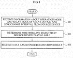
- FIG. 2 is a flowchart illustrating a communication method of a destination device according to an embodiment.
- FIG. 2 illustrates operations of the destination device when a source device switches a link transmitting data, when the link in use to transmit the data is blocked, in a contention free period.
- the destination device receives information about an operation mode used for the source device to transmit data and a relay mode of a relay device from the source device in an initialization process. Moreover, the destination device receives a preset link change interval from the source device in operation 201.
- the relay mode of the relay device may include at least one of the FD mode and the HD mode.
- a first period and a second period used in the HD relay mode of the relay device are no longer available when a first link is a selected link.
- the link change interval may start from a start point of the first period when the source device switches the second link to the first link.
- the FD mode, the HD mode, the first period, and the second period refer to the descriptions with reference to FIG. 1 .
- the operation mode including at least one of the normal mode and the alternation mode also refers to the descriptions with reference to FIG. 1 .
- the destination device determines whether a link selected by the source device among the first link directly connected from the source device to the destination device and the second link connected from the source device to the destination device via the relay device is available in operation 203.
- the destination device may determine whether the selected link is available based on whether data is received through the selected link for predetermined time.
- the predetermined time may be time over the data sensing time from a start of the preset link change interval.
- the destination device may switch a link of the destination device from the second link to the first link at a start of each first period in order to identify whether the source device switches the second link to the first link.
- the destination device may consider that the link change interval starts from the start point of the first period in which data is received through the first link.
- the destination device may switch the link of the destination device from the first link to the second link at a start of a next second link among a next first period and the next second period.
- the source device may transmit data to the relay device in the next first period, and the relay device may transmit the data to the destination device in the next second period.
- the destination device receives the data based on a determination result in operation 205.
- the destination device identifies whether the source device switches to the selected link. Then, when the source device is identified to switch to the selected link, the destination device adjusts a directional antenna of the destination device toward the selected link and stands by for receipt of the data.
- the destination device may switch the selected link to an unselected link.
- the destination device When the operation mode is the alternation mode and data is received through the selected link, the destination device operates as follows.
- the destination device may receive data through the selected link at the start of the preset link change interval.
- the destination device may switch to the unselected link in a next link change interval to the preset link change interval. Then, the destination device may receive data from a start of the next link change interval.
- operations of the destination device in a relay mode of the relay device and an operation mode are as follows.
- the destination device may not switch the link to the first link even if data is not received through a link via the relay device, which is the second link, during the second period.
- the destination device may maintain the selected link even if data is not received through the selected link during the data sensing time.
- MAC media access control
- the destination device may maintain the selected link, instead of exchanging links in the next link change interval to the preset link change interval.
- the destination device may determine whether the first link used to receive data from the source device is blocked. Here, the destination device may identify whether the source device switches the first link.
- the destination device adjusts a directional antenna of the destination device toward the second link and stands by for receipt of the data.
- the destination device switches the first link to the second link after the data sensing time based on the link change interval preset by the source device and receives the data using the second link.
- the destination device receives the data from the source device using the same first link.
- the destination device may switch a link from a direct link to a relay link. That is, when the operation mode is the normal mode and the destination device does not receive available data from the source device within the data sensing time from the start point of the preset link change interval, the destination device may switch the direct link to the relay link.
- the destination device when the destination device does not receive data in desired order, the destination device may maintain the current link instead of changing the link.
- the destination device may maintain the current first link instead of switching to the second link based on the alternation mode.
- FIG. 3 is a flowchart illustrating a communication method of a relay device according to an embodiment.
- FIG. 3 illustrates an operation of the relay device when the source device switches a link transmitting data when the link in use to transmit data is blocked in the contention free period.
- the relay device stands by for receipt of data from the source device at a start point of a preset link change interval in operation 301.
- the first link is a link directly connected from the source device to the destination device
- the second link is a link connected from the source device to the destination device via the relay device.
- the relay device adjusts a direction of a directional antenna of the relay device for predetermined time from the start point of the preset link change interval and stands by for receipt of the data through the second link from the source device.
- the relay device receives the data from the source device in operation 303 and transmits the data to the destination device in operation 305.
- the relay device may receive information about a first period and a second period from the source device. Then, the relay device receives the data from the source device in the first period, and transmits the data to the destination device in the second period.
- the first period is for a relay link between the source device and the relay device
- the second period is for a relay link between the relay device and the destination device.
- the relay device may receive, from the source device, a request frame to identify whether the data transmitted by the source device to the relay device is transmitted to the destination device.
- the relay device may transmit a response frame indicating whether the data is transmitted to the destination device in response to the request frame.
- the relay device may operate in at least one of the FD mode and the HD mode.
- the first link is switched to the second link in the preset link change interval, and the data is transmitted through the second link after the data sensing time for the destination device to detect whether the data is transmitted through the first link.
- a transmitter transmits the data in the same manner as the FD mode when the first link is used, and the transmitter transmits the data based on the first period and the second period when the second link is used.
- the relay device When the relay mode is the FD mode, the relay device adjusts a direction of another directional antenna of the relay device for predetermined time from the start point of the preset link change interval and stands by to receive the data through the link toward the destination device.
- the relay device may change an operation of the directional antenna of the relay device to a transmission/reception state based on a type of each frame received by the relay device and a policy on an acknowledgement signal.
- operations of the relay device on the assumption that the relay device transmits and receives data through the second link are described.
- the relay device receives information about the first period and the second period from the source device.
- the relay device receives data from the source device in the first period and transmits the data to the destination device in the second period.
- the relay device may receive, from the source device, a request frame to identify whether the data transmitted by the source device to the relay device is transmitted to the destination device, described above.
- the relay device may transmit a response frame indicating whether the data is transmitted to the destination device.
- the request frame may be a relay ACK request frame
- the response frame may be a relay ACK response frame.
- the respective frames refer to the descriptions in Tables 1 and 2 with reference to FIG. 1 .
- the source device and the destination device may have different time instances to determine whether a link is blocked when a link switch is needed due to the blockage of the link in use to transmit data. That the source device and the destination device have different time instances denotes that the respective devices may have different periods of time for beam forming to adjust transmission and reception terminals toward a new link for link switches.
- two parameters are used, which are a link change interval and data sensing time to prevent the above-mentioned problem.
- a switch of a link transmitting data is allowed only in a certain point of a determined period within a reserved block, thereby solving a problem due to transmission of data in a random moment.
- the determined period may be a link change interval
- the source device may inform the relay device and the destination device of a link change interval value before transmission of data to share information about the determined period.
- the source device may switch the link and transmit the data in a next link change interval.
- the destination device may not recognize the link switch by the source device, since the destination device properly receives data but ACK in response to the receipt of the data is lost during transmission by the destination device to the source device, so that the source device may not recognize ACK with respect to the transmission of the data.
- the source device may not immediately transmit the data in a next link change interval but transmit the data after a predetermined time, for example, a data sensing time.
- the destination device is not aware of whether a link switch occurs in the next link change interval, and thus stands by in the same link before the switch. However, when data is not transmitted after the predetermined time, the destination device switches the link.
- the destination device switches the link after the predetermined time defined as the data sensing time, and the source device transmits the data using a switched link after time based on the data sensing time and switching time. This is because it is secure that the source device transmits time the data after time based on the switching time used for the destination device to switch the link after the data sensing time.
- the switching time when the switching time is smaller than a propagation delay transmitted from the source device to the destination device, the switching time may be ignored.
- the destination device switches the link after the data sensing time, and the source device transmits the data through the switched data after the data sensing time. Accordingly, since the destination device prepares in advance in the switched link, the destination device may properly receive the data transmitted from the source device.
- the relay device when the relay device is a DF relay using the HD relay mode, the relay device decodes, then encodes and transmits data to the destination device in order to transmit the data through a relay link, and thus about double a number of slots are used as compared with in direct transmission.
- the two links connected to the relay device which are an S-R link and an R-D link, have different qualities, different periods of time may be used to transmit the same data.
- the HD relay mode there is a need for fields representing length of two blocks, which are respectively called a first period and a second period.
- Values of the two fields may be set or updated through a beam forming result obtained before the source device transmits the data or link quality information requested and obtained while the data is transmitted.
- the source device defines an information element (IE) that is a group of related parameters. The source device transmits a related parameter based on the IE to the destination device via the relay device, and the destination device may transmit corresponding information that is a related parameter to the source device via the relay device in response.
- IE information element
- the source device When the relay link is used, the source device transmits a packet of determined size in order to transmit a data packet to the relay device and to receive ACK after a short inter-frame space (SIFS) within the first period. If the source device transmits only one MAC service data unit (MSDU), it is proper that a value of MSDU + SIFS + ACK + SIFS is adjusted to be the same as a vale of the first period.
- SIFS short inter-frame space
- the relay device may determine a size of a packet to be transmitted to the destination device in order to receive and encode the packet and to receive ACK after SIFS within the second period. If the relay device transmits only one MSDU, it is proper that a value of MSDU + SOFS + ACK + SIFS is adjusted to be the same as a value of the second period.
- the relay device since ACK of the second period is transmitted by the relay device to the destination device, the relay device is aware of a status of the R-D link whereas the source device is not aware of a status of the R-D link.
- the source device may transmit a relay ACK request frame in Table 1 to the relay device in a next first period and request information about whether a frame is properly transmitted through the R-D link. Further, the relay device may transmit a relay ACK response frame in Table 2 to the source device in response to the relay ACK request frame.
- formats of the relay ACK request frame and the relay ACK response frame are the same as in Tables 1 and 2, a request for BlcokAck and transmission of corresponding Block Ack.
- the source device may identify that the data, which is the frames, is successfully transmitted to the destination device. Further, since the source device may need to complete transmission of the data or the frames within a reserved resource, the source device leaves time for exchange of the data frame in a last first period, so that transmission of the frame is completely identified in the current reserved block.
- the source device may perform a different link switch operation depending on a type of a link among the direct link and the relay link.
- the source device When the direct link is used, the source device performs a link switch in each link change interval as in the FD relay mode. However, when the relay link is used, the source device operates in the first period and the second period. When the source device switches a link from the direct link to the relay link, that is, when a link change interval starts, the first period starts.
- the source device transmits a data frame to the destination device based on the first period and the second period.
- the source device may determine that the relay link is blocked and switch to the direct link.
- the source device Since the source device performs a link switch to transmit data, the source device determines a link switch and then immediately switches to the direct link at a start of a next period. A link change interval starts when the source device switches to the direct link, and the source device operates using the link.
- the destination device is not aware of whether the source device determines a link switch but is aware only that data or a frame to receive is not received yet. Thus, the destination device periodically identifies whether the source device performs a link switch.
- time when the source device transmits a data frame is the first period, and thus the destination device stands by for a data or a frame from a direction to the direct link in each first period.
- stand by time of the destination device may be determined optionally by the source device.
- the source device unconditionally transmits data or a frame at a start of the first period when a link switch is performed, and thus the standby time of the destination device may be set to, for example, about data sensing time.
- the destination device may recognize that a link switch occurs and continue to use the direct link. Here, the link change interval and the data sensing time are used again.
- the destination device adjusts an antenna toward the relay device and switches to the relay link to stand by for the data or frame from a start of the second period.
- Values of the link change interval, the data sensing time, the first period, and the second period may be determined by the source device as well as the relay use mode value.
- Resources that are time blocks respectively allocated to the source device and the destination device start by any one of the link change interval and the first period, and the source device, the relay device, and the destination device participating in a relay operation within one link change interval may need to use the same link.
- a new link change interval starts immediately after a previous link change interval but does not exceed a range of the resources allocated to the respective devices.
- the source device may need to start transmission of a frame to the destination device using the direct link at a start of a first resource, which is a time block, allocated to the source device and the destination device. Then, the source device may need to use a link finally successfully used in transmission of a frame at a start of all allocated resources.
- the source device transmits data to the destination device alternately using the direct link and the relay link.
- the source device may need to change a link transmitting a frame in a start of each link change interval.
- the source device may switch the link for transmission of a frame at a start of a next link change interval.
- the source device may transmit the frame to the destination device using a relay of the relay device.
- the source device may switch the link for transmission of a frame at a start of a next link change interval or a next first period.
- the source device may transmit the frame to the destination device using the direct link.
- FIG. 4 illustrates a frame transmission protocol added when data is transmitted by the AF relay device using the FD relay mode according to an embodiment.
- the source device may need to start transmitting a frame after data sensing time at a start of the next link change interval.
- the source device may need to change a link used for transmission of the frame at a start of each link change interval, ignoring the data sensing time.
- the destination device when the destination device does not receive an available frame from the source device within the data sensing time at a start of the link change interval, the destination device may immediately switch a link to try to receive the frame from the source device through the relay device.
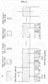
- FIG. 5 illustrates a frame structure of 802.11 WLAN used in an embodiment.
- the destination device maintains the current link but does not switch the link.
- the destination device may not switch the link at the next link change interval.
- the source device When the source device desires to use any one of the direct link and the relay link and to transmit a changed frame, the source device transmits the frame after data sensing time in a next link change interval in order to inform the destination device that the source device operates using the other link. This instance is the only example where the data sensing time is used in the alternation mode.
- FIG. 6 illustrates a frame transmission protocol added when data is transmitted by the DF relay device using the HD relay mode according to an embodiment.
- the relay device When the relay device operates as the DF relay device using the HD relay mode and the alternation mode is used, a frame exchange is repeatedly performed for two blocks of the first period and the second period as long as the relay device is used, which means as long as the relay link is used.
- the source device transmits a frame to the relay device, and the relay device responds to the source device within SIFS if necessary.
- the relay device relays the frame received from the source device to the destination device, and the destination device responds to the relay device within the SIFS if necessary.
- a size of the first period and the second period may be the most recently transmitted value.
- the first period and the second period are effective only when the source device and the destination device exchange frames via the relay device, that is, when the relay link is used.
- the link change interval is effective only when the source device and the destination device exchange frames through the direct link.
- the first period starts at an end of the link change interval. Further, when the relay link is switched to the direct link, the link change interval starts at an end of the second period.
- the source device may transmit a relay ACK request frame as in Table 1 to the relay device in order to identify whether all frames transmitted are successfully transmitted to the destination device via the relay device.
- the relay device receiving the relay ACK request frame responds to the source device with a relay ACK response frame, and sets a BlockAck bitmap field of the relay ACK response frame in order to show which frame is successfully received.
- the source device When the source device determines to switch the direct link to the relay link at a start of a next link change interval, the source device starts transmitting a frame at the start of the next link change interval.
- the destination device may need to switch the link, and the first period may be considered to start at a start point of a corresponding link change interval.
- the link change interval starts at the end of the second period, and the source device may start transmitting data or a frame using the direct link.
- the destination device switches to the direct link in each first period and listens to a medium toward the source device.
- the destination device receives an available frame from the source device, the destination device maintains the direct link, and the link change interval is considered to start at the start of the first period.
- the destination device switches a link at the start of the second period and tries to receive a frame via the relay device.
- the destination device may not switch to the direct link even if the destination device does not receive any frame during the second frame.
- the AF relay device using the FD relay mode operates as follows for a relay operation.
- the AF relay device using the FD relay mode in an allocated resource operates in the AF mode.
- the AF mode means that the AF relay device using the FD relay mode amplifies a signal received with respect to each frame detected at a radio frequency (RF) in reception and simultaneously retransmits the signal via another RF in transmission within an operation resource.
- RF radio frequency
- the AF relay device using the FD relay mode in a start of the allocated resource initializes an RF module toward the source device to a reception state and initializes an RF module toward the destination device to a transmission state.
- the AF relay device using the FD relay mode switches a state of each RF module from a transmission mode to a reception mode or vice versa based on a type of a frame and an ACK policy with respect to each received frame.
- the source device may periodically monitor quality of a previous link. To this end, the source device may use the above frame exchange protocols.
- the source device may obtain information about a status of a channel using an existing link adaptation mechanism.
- the link before the switch is the relay link, the source device uses the existing link adaptation mechanism but further needs the following process.
- the following process is further transmission of information about a status of the R-D link in addition to transmission of information about a status of the S-R link, which is a conventional process, when the relay device responds to the source device with respect to a state of a channel.
- the source device may switch to the previous link.
- the communication method of a source device, a destination device, and a relay device may be recorded in non-transitory computer-readable media including program instructions to implement various operations embodied by a computer.
- the media may also include, alone or in combination with the program instructions, data files, data structures, and the like.
- Examples of non-transitory computer-readable media include magnetic media such as hard disks, floppy disks, and magnetic tape; optical media such as CD ROM disks and DVDs; magneto-optical media such as optical discs; and hardware devices that are specially configured to store and perform program instructions, such as read-only memory (ROM), random access memory (RAM), flash memory, and the like.
- Examples of program instructions include both machine code, such as produced by a compiler, and files containing higher level code that may be executed by the computer using an interpreter.
- the described hardware devices may be configured to act as one or more software modules in order to perform the operations of the above-described embodiments, or vice versa.
Landscapes
- Engineering & Computer Science (AREA)
- Signal Processing (AREA)
- Computer Networks & Wireless Communication (AREA)
- Mobile Radio Communication Systems (AREA)
- Detection And Prevention Of Errors In Transmission (AREA)
- Small-Scale Networks (AREA)
- Data Exchanges In Wide-Area Networks (AREA)
- Two-Way Televisions, Distribution Of Moving Picture Or The Like (AREA)
Claims (14)
- Kommunikationsverfahren einer Quellenvorrichtung, umfassend:Erfassen eines Zustands einer ersten Verbindung, die von der Quellenvorrichtung zu einer Zielortvorrichtung direkt verbunden ist, oder eines Zustands einer zweiten Verbindung, die von der Quellenvorrichtung zur Zielortvorrichtung über eine Relaisvorrichtung verbunden ist (103);Auswählen irgendeiner der ersten Verbindung und der zweiten Verbindung basierend auf einem Ergebnis der Erfassung (105); undÜbertragen von Daten unter Verwendung der ausgewählten Verbindung (107),wobei das Auswählen irgendeiner der ersten Verbindung und der zweiten Verbindung (105) ein Schalten irgendeiner der ersten Verbindung und der zweiten Verbindung zur basierend auf dem Ergebnis der Erfassung ausgewählten Verbindung in einem voreingestellten Verbindungsänderungsintervall umfasst,wobei das Kommunikationsverfahren weiterhin ein Informieren der Zielortvorrichtung und der Relaisvorrichtung über Parameter (101) umfasst, die das voreingestellte Verbindungsänderungsintervall oder eine Datenerfassungszeit für die Zielortvorrichtung, um zu erfassen, ob Daten über die ausgewählte Verbindung übertragen werden, enthalten.
- Kommunikationsverfahren nach Anspruch 1, das weiterhin ein periodisches Schalten zu einer nicht ausgewählten Verbindung umfasst, um ein Qualität der nicht ausgewählten Verbindung unter der ersten Verbindung und der zweiten Verbindung zu überwachen.
- Kommunikationsverfahren nach Anspruch 2, umfassend:Übertragen, zur Relaisvorrichtung, eines Anfrage-Frames, um eine Qualität der ersten Verbindung zu überwachen, wenn die erste Verbindung zur zweiten Verbindung geschaltet wird, um die nicht ausgewählte Verbindung zu überwachen; undEmpfangen eines Antwort-Frames, der Information über die Qualität der ersten Verbindung enthält, in Antwort auf den Anfrage-Frame.
- Kommunikationsverfahren nach Anspruch 2, umfassend:Senden, zur Relaisvorrichtung, eines Anfrage-Frames, um eine Qualität einer Verbindung zwischen der Quellenvorrichtung und der Relaisvorrichtung der zweiten Verbindung zu überwachen, wenn die zweite Verbindung zur ersten Verbindung geschaltet wird, um die nicht ausgewählte Verbindung zu überwachen; undEmpfangen, in Antwort auf den Anfrage-Frame, eines Antwort-Frames, der Information über die Qualität der Verbindung zwischen der Quellenvorrichtung und der Relaisvorrichtung der zweiten Verbindung und Information über eine Qualität einer Verbindung zwischen der Relaisvorrichtung und der Zielortvorrichtung enthält, welche durch die Relaisvorrichtung von der Zielortvorrichtung empfangen wird.
- Kommunikationsverfahren nach Anspruch 1, wobei das Auswählen irgendeiner der ersten Verbindung und der zweiten Verbindung (105) irgendeine der ersten Verbindung und der zweiten Verbindung basierend auf einem Bestätigungs-(ACK-)Signal in Bezug auf vorherige zur Zielortvorrichtung über die ausgewählte Verbindung gesendete Daten oder Verbindungsqualitätsinformation, die von einem Frame erhalten ist, um einen Zustand eines Kanals zu schätzen, auswählt.
- Kommunikationsverfahren nach Anspruch 5, wobei das Auswählen irgendeiner Verbindung (105) irgendeine Verbindung basierend darauf auswählt, ob die Verbindung blockiert ist oder ob eine Qualität der Verbindung einer voreingestellten Qualität entspricht.
- Kommunikationsverfahren nach Anspruch 1, wobei das Auswählen irgendeiner der ersten Verbindung und der zweiten Verbindung (105) die ausgewählte Verbindung in einem nächsten Verbindungsänderungsintervall zu einem Verbindungsänderungsintervall, in welchem bestimmt wird, dass die erste Verbindung oder die zweite Verbindung nicht verfügbar ist, zu einer nicht ausgewählten Verbindung schaltet.
- Kommunikationsverfahren nach Anspruch 1, wobei das Schalten irgendeiner der ersten Verbindung und der zweiten Verbindung zur ausgewählten Verbindung (105) ein Erhöhen eines Sendeantennengewinns von Daten über eine nicht ausgewählte Verbindung durch Einstellen einer Richtung einer Richtantenne der Quellenvorrichtung basierend auf einem im Voraus über die nicht ausgewählte Verbindung erhaltenen Ergebnis einer Strahlformung umfasst.
- Kommunikationsverfahren nach Anspruch 1, wobei das Senden der Daten unter Verwendung der ausgewählten Verbindung die Daten unter Verwendung der ausgewählten Verbindung nach einer Zeit basierend auf einer Datenerfassungszeit für die Zielortvorrichtung, um zu erfassen, ob Daten über die ausgewählte Verbindung gesendet werden, oder einer für die Zielortvorrichtung verwendeten Schaltzeit, um die ausgewählte Verbindung zu einer nicht ausgewählten Verbindung zu schalten, sendet.
- Kommunikationsverfahren nach Anspruch 1, das weiterhin ein Senden, zur Zielortvorrichtung und zur Relaisvorrichtung, von Information über einen Betriebsmode und einen Relaismode der Relaisvorrichtung umfasst, die verwendet werden, um die Daten zu senden (101).
- Kommunikationsverfahren nach Anspruch 10, wobei der Relaismode der Relaisvorrichtung wenigstens einen eines Vollduplex-(FD-)Modes, in welchem die erste Verbindung zur zweiten Verbindung im voreingestellten Verbindungsänderungsintervall geschaltet wird und die Daten nach einer Datenerfassungszeit für die Zielortvorrichtung, um zu erfassen, ob die Daten über die erste Verbindung gesendet werden, über die zweite Verbindung gesendet werden, und eines Halbduplex-(HD-)Modes, in welchem die Relaisvorrichtung die Daten auf dieselbe Weise wie beim FD-Mode sendet, wenn die erste Verbindung verwendet wird, und die Relaisvorrichtung die Daten basierend auf einer ersten Periode für eine Relaisverbindung zwischen der Quellenvorrichtung und der Relaisvorrichtung und einer zweiten Periode für eine Relaisverbindung zwischen der Relaisvorrichtung und der Zielortvorrichtung sendet, wenn die zweite Verbindung verwendet wird.
- Kommunikationsverfahren nach Anspruch 11, wobei die erste Periode und die zweite Periode basierend auf wenigstens einem eines Strahlformungsergebnisses, das erhalten wird, bevor die Daten gesendet werden, und einer Verbindungsqualitätsinformation, die erhalten wird, während die Daten gesendet werden, wenn der HD-Mode verwendet wird, eingestellt oder upgedated werden, die erste Periode startet, wenn die Quellenvorrichtung die erste Verbindung zur zweiten Verbindung schaltet, und das voreingestellte Verbindungsänderungsintervall neu startet, wenn die Quellenvorrichtung die zweite Verbindung zur ersten Verbindung schaltet.
- Kommunikationsverfahren nach Anspruch 10, wobei der Betriebsmode wenigstens einen eines normalen Modes, in welchem die Daten zur Zielortvorrichtung unter Verwendung irgendeiner Verbindung gesendet werden, bis bestimmt wird, dass irgendeine der ersten Verbindung und der zweiten Verbindung nicht verfügbar ist, und eines Wechsel-Modes, in welchem die Daten zur Zielortvorrichtung abwechselnd unter Verwendung der ersten Verbindung, die eine direkte Verbindung ist, und der zweiten Verbindung bei jedem Startpunkt des voreingestellten Verbindungsänderungsintervalls gesendet werden, umfasst.
- Kommunikationsverfahren nach Anspruch 13, das ein Senden der Daten nach einer Datenerfassungszeit eines nächsten Verbindungsänderungsintervalls zu dem Verbindungsänderungsintervall umfasst, um die Zielortvorrichtung zu informieren, dass ein Betrieb über die ausgewählte Verbindung wiederaufgenommen wird, wenn die Quellenvorrichtung bestimmt, ein Senden der Daten im Wechsel-Mode wiederaufzunehmen.
Priority Applications (1)
| Application Number | Priority Date | Filing Date | Title |
|---|---|---|---|
| EP19150010.7A EP3512119B1 (de) | 2010-02-05 | 2011-02-07 | Kommunikationsverfahren zwischen einer quellvorrichtung, einer zielvorrichtung und einer relaisvorrichtung |
Applications Claiming Priority (5)
| Application Number | Priority Date | Filing Date | Title |
|---|---|---|---|
| KR20100011214 | 2010-02-05 | ||
| KR20100021933 | 2010-03-11 | ||
| KR20100043306 | 2010-05-10 | ||
| KR20110010136 | 2011-02-01 | ||
| PCT/KR2011/000757 WO2011096752A2 (ko) | 2010-02-05 | 2011-02-07 | 소스 장치, 데스티네이션 장치 및 릴레이 장치의 통신 방법 |
Related Child Applications (2)
| Application Number | Title | Priority Date | Filing Date |
|---|---|---|---|
| EP19150010.7A Division-Into EP3512119B1 (de) | 2010-02-05 | 2011-02-07 | Kommunikationsverfahren zwischen einer quellvorrichtung, einer zielvorrichtung und einer relaisvorrichtung |
| EP19150010.7A Division EP3512119B1 (de) | 2010-02-05 | 2011-02-07 | Kommunikationsverfahren zwischen einer quellvorrichtung, einer zielvorrichtung und einer relaisvorrichtung |
Publications (3)
| Publication Number | Publication Date |
|---|---|
| EP2533468A2 EP2533468A2 (de) | 2012-12-12 |
| EP2533468A4 EP2533468A4 (de) | 2014-03-26 |
| EP2533468B1 true EP2533468B1 (de) | 2019-04-10 |
Family
ID=44355991
Family Applications (2)
| Application Number | Title | Priority Date | Filing Date |
|---|---|---|---|
| EP19150010.7A Active EP3512119B1 (de) | 2010-02-05 | 2011-02-07 | Kommunikationsverfahren zwischen einer quellvorrichtung, einer zielvorrichtung und einer relaisvorrichtung |
| EP11740048.1A Active EP2533468B1 (de) | 2010-02-05 | 2011-02-07 | Kommunikationsverfahren zwischen einer quellvorrichtung, einer zielvorrichtung und einer relaisvorrichtung |
Family Applications Before (1)
| Application Number | Title | Priority Date | Filing Date |
|---|---|---|---|
| EP19150010.7A Active EP3512119B1 (de) | 2010-02-05 | 2011-02-07 | Kommunikationsverfahren zwischen einer quellvorrichtung, einer zielvorrichtung und einer relaisvorrichtung |
Country Status (5)
| Country | Link |
|---|---|
| US (2) | US8908550B2 (de) |
| EP (2) | EP3512119B1 (de) |
| JP (5) | JP5788909B2 (de) |
| CN (1) | CN102792642B (de) |
| WO (1) | WO2011096752A2 (de) |
Families Citing this family (20)
| Publication number | Priority date | Publication date | Assignee | Title |
|---|---|---|---|---|
| JP5609708B2 (ja) * | 2011-02-22 | 2014-10-22 | 富士通株式会社 | 中継機,中継方法,送信機,受信機及び無線通信システム |
| GB2500410A (en) * | 2012-03-21 | 2013-09-25 | Renesas Mobile Corp | Swapping an actual channel on a secondary link with a shadow channel on a primary link with when the secondary link is no longer available |
| JP5907033B2 (ja) | 2012-09-28 | 2016-04-20 | ブラザー工業株式会社 | 通信装置 |
| JP6036118B2 (ja) * | 2012-09-28 | 2016-11-30 | ブラザー工業株式会社 | 通信装置 |
| US9294246B2 (en) * | 2013-03-19 | 2016-03-22 | Electronics And Telecommunications Research Institute | Wireless communication device using common control channel and wireless communication method using the same |
| CN103476087B (zh) * | 2013-09-04 | 2016-08-03 | 北京邮电大学 | 一种提高无线网络中继选择速率的方法及系统 |
| WO2015069047A1 (ko) * | 2013-11-06 | 2015-05-14 | 주식회사 케이티 | 무선랜 시스템에서 데이터 송수신 방법 및 장치 |
| CN105612806A (zh) | 2013-11-06 | 2016-05-25 | Kt株式会社 | 在无线局域网系统中传输和接收数据的方法和设备 |
| CN103973592B (zh) * | 2014-05-16 | 2017-12-05 | 华为技术有限公司 | 信元处理方法及装置 |
| US9973257B1 (en) * | 2015-08-19 | 2018-05-15 | Sprint Spectrum L.P. | RF slave repeater management |
| KR102432712B1 (ko) * | 2015-11-30 | 2022-08-16 | 삼성전자주식회사 | 무선 통신 시스템에서 릴레이 링크 설정을 위한 방법 및 장치 |
| JP6563345B2 (ja) * | 2016-01-25 | 2019-08-21 | 京セラ株式会社 | 無線中継装置および無線中継方法 |
| JP6957496B2 (ja) | 2016-03-23 | 2021-11-02 | フェデックス コーポレイト サービシズ,インコーポレイティド | 無線ノードネットワーク内のノードのブロードキャスト設定を自動調整するための無線ノードベースの方法、その方法を実行する命令を含む非一時的コンピュータ可読媒体、および無線ノードネットワークにおける自動調整ブロードキャストノード装置 |
| CN105897478B (zh) * | 2016-04-12 | 2019-02-05 | 腾讯科技(深圳)有限公司 | 一种链路决策的方法及决策设备 |
| CN107404372B (zh) * | 2016-05-20 | 2019-02-22 | 北京小米移动软件有限公司 | 一种通信方法及装置 |
| CN110545570B (zh) * | 2016-08-09 | 2020-07-21 | 华为技术有限公司 | 一种系统消息的发送方法和设备 |
| US10530465B2 (en) * | 2018-05-30 | 2020-01-07 | Motorola Solutions, Inc. | Apparatus, system and method for generating a virtual assistant on a repeater |
| US11528075B2 (en) | 2019-05-16 | 2022-12-13 | Qualcomm Incorporated | Joint beam management for backhaul links and access links |
| US11778533B2 (en) * | 2019-08-02 | 2023-10-03 | Comcast Cable Communications, Llc | Path optimization in a mesh network |
| JP2022084339A (ja) * | 2020-11-26 | 2022-06-07 | Necプラットフォームズ株式会社 | 第1の通信装置、通信システム、方法及びプログラム |
Family Cites Families (24)
| Publication number | Priority date | Publication date | Assignee | Title |
|---|---|---|---|---|
| US6081510A (en) | 1998-08-19 | 2000-06-27 | Motorola, Inc. | Method and apparatus for robust operation of data transmission during adverse radio-link conditions |
| JP3985828B2 (ja) * | 2004-07-27 | 2007-10-03 | 松下電工株式会社 | 通信ルートの構築方法及び通信端末 |
| US8159999B2 (en) | 2005-01-25 | 2012-04-17 | Interdigital Technology Corporation | Peer-to-peer wireless communication system |
| FR2904259B1 (fr) | 2006-07-31 | 2013-02-22 | Oberthur Card Syst Sa | Support d'information presentant un connecteur male et son procede de fabrication |
| KR101210344B1 (ko) | 2006-09-08 | 2012-12-10 | 한국과학기술원 | 좌표 회전 릴레이 시스템 및 좌표 회전 릴레이 방법 |
| US20080112369A1 (en) | 2006-11-13 | 2008-05-15 | Samsung Electronics Co., Ltd. | Method and apparatus for allocating bandwidth of wireless network, and method and apparatus for transmitting and receiving data on the network |
| KR100878538B1 (ko) | 2006-11-13 | 2009-01-13 | 삼성전자주식회사 | 무선 네트워크에서 대역폭 할당 방법 및 장치, 데이터송수신 방법 및 장치 |
| US9942883B2 (en) | 2006-11-13 | 2018-04-10 | Samsung Electronics Co., Ltd. | Method and apparatus for allocating bandwidth of wireless network where both wide-band and narrow-band signals are transmitted, and method and apparatus for transmitting and receiving data on the network |
| US20080112370A1 (en) | 2006-11-13 | 2008-05-15 | Samsung Electronics Co., Ltd. | Method and apparatus for allocating bandwidth of wireless network, and method and apparatus for transmitting and receiving data on the network |
| WO2008107984A1 (ja) | 2007-03-07 | 2008-09-12 | Panasonic Corporation | 携帯端末装置および携帯端末システム |
| KR20080109617A (ko) | 2007-06-13 | 2008-12-17 | 한국전자통신연구원 | 다중 경로 관리 방법, 다중 경로를 이용한 데이터 송수신방법 및 그 장치 |
| KR20090048159A (ko) | 2007-11-09 | 2009-05-13 | 엘지전자 주식회사 | 무선국 사이의 다이렉트 링크를 관리하는 방법 |
| KR100969147B1 (ko) | 2007-11-29 | 2010-07-08 | 한국전자통신연구원 | 협력 수신 다이버시티 동작 방법, 선택적 협력 통신 방법및 시스템 |
| WO2009072815A2 (en) | 2007-12-04 | 2009-06-11 | Lg Chem, Ltd. | Integrated wide viewing film and in-plan switching liquid crystal display with the same |
| WO2009072825A2 (en) * | 2007-12-05 | 2009-06-11 | Electronics And Telecommunications Research Institute | Apparatus and method for transmitting and receiving data in wireless communication system |
| JP2009164868A (ja) | 2008-01-07 | 2009-07-23 | Panasonic Corp | インターフェース装置、不揮発性記憶装置、通信システム、および通信方法 |
| WO2009092155A1 (en) * | 2008-01-22 | 2009-07-30 | Nortel Networks Limited | Path selection for a wireless system with relays |
| US8670440B2 (en) * | 2008-05-13 | 2014-03-11 | Electronics And Telecommunications Research Institute | Data transceiving apparatus and method in centralized MAC-based wireless communication system |
| KR101231376B1 (ko) | 2008-05-23 | 2013-02-07 | 한국전자통신연구원 | 분산 매체 접근제어를 사용하는 무선통신 시스템에서 다중 경로를 사용한 데이터 송수신 장치 및 그 방법 |
| US9236933B2 (en) * | 2008-05-23 | 2016-01-12 | Electronics And Telecommunications Research Institute | Apparatus and method for transmitting and receiving data using multi-path in wireless communication system of distributed MAC |
| WO2010006650A1 (en) * | 2008-07-17 | 2010-01-21 | Nokia Siemens Networks Oy | Selection of connection type in cellular telecommunications system |
| US8155049B2 (en) * | 2009-04-29 | 2012-04-10 | Hong Kong Technologies Group Limited | Method and device for user cooperative communication |
| EP2452469A1 (de) * | 2009-07-10 | 2012-05-16 | Nokia Siemens Networks OY | Verfahren und vorrichtung zur verkehrsweiterleitung |
| US8908624B2 (en) * | 2009-10-22 | 2014-12-09 | Interdigital Patent Holdings, Inc. | Method and apparatus for a two-way relaying scheme with physical layer network coding |
-
2011
- 2011-02-07 US US13/577,121 patent/US8908550B2/en active Active
- 2011-02-07 EP EP19150010.7A patent/EP3512119B1/de active Active
- 2011-02-07 EP EP11740048.1A patent/EP2533468B1/de active Active
- 2011-02-07 JP JP2012551924A patent/JP5788909B2/ja active Active
- 2011-02-07 WO PCT/KR2011/000757 patent/WO2011096752A2/ko active Application Filing
- 2011-02-07 CN CN201180012773.6A patent/CN102792642B/zh active Active
-
2014
- 2014-11-21 US US14/550,365 patent/US9584212B2/en active Active
-
2015
- 2015-04-06 JP JP2015077886A patent/JP5993977B2/ja active Active
- 2015-10-21 JP JP2015207048A patent/JP6193952B2/ja active Active
-
2017
- 2017-08-10 JP JP2017155671A patent/JP6449949B2/ja active Active
-
2018
- 2018-12-06 JP JP2018228971A patent/JP6655699B2/ja active Active
Non-Patent Citations (1)
| Title |
|---|
| None * |
Also Published As
| Publication number | Publication date |
|---|---|
| EP2533468A2 (de) | 2012-12-12 |
| JP6449949B2 (ja) | 2019-01-09 |
| JP2019075794A (ja) | 2019-05-16 |
| JP6193952B2 (ja) | 2017-09-06 |
| US20150078193A1 (en) | 2015-03-19 |
| US9584212B2 (en) | 2017-02-28 |
| JP2016054492A (ja) | 2016-04-14 |
| WO2011096752A2 (ko) | 2011-08-11 |
| EP2533468A4 (de) | 2014-03-26 |
| JP2015167364A (ja) | 2015-09-24 |
| JP6655699B2 (ja) | 2020-02-26 |
| EP3512119B1 (de) | 2021-12-22 |
| EP3512119A3 (de) | 2019-10-02 |
| JP5993977B2 (ja) | 2016-09-21 |
| JP5788909B2 (ja) | 2015-10-07 |
| WO2011096752A3 (ko) | 2011-12-01 |
| CN102792642B (zh) | 2016-08-17 |
| US8908550B2 (en) | 2014-12-09 |
| JP2013519290A (ja) | 2013-05-23 |
| JP2018014728A (ja) | 2018-01-25 |
| EP3512119A2 (de) | 2019-07-17 |
| US20130039201A1 (en) | 2013-02-14 |
| CN102792642A (zh) | 2012-11-21 |
Similar Documents
| Publication | Publication Date | Title |
|---|---|---|
| EP2533468B1 (de) | Kommunikationsverfahren zwischen einer quellvorrichtung, einer zielvorrichtung und einer relaisvorrichtung | |
| KR102198348B1 (ko) | 무선 통신 시스템에서 릴레이 링크 셋업 방법 및 장치 | |
| US9236933B2 (en) | Apparatus and method for transmitting and receiving data using multi-path in wireless communication system of distributed MAC | |
| KR102220689B1 (ko) | 소스 장치, 데스티네이션 장치 및 릴레이 장치의 통신 방법 | |
| US10230448B2 (en) | System and method for robust relay communication | |
| US8588124B2 (en) | Method and apparatus for data communication in radio network | |
| WO2008088190A1 (en) | Method and system for device discovery in wireless communication | |
| KR20080022208A (ko) | 스마트 안테나를 갖는 무선 통신 시스템에서 데이터를송수신하는 방법 및 장치 | |
| KR101231376B1 (ko) | 분산 매체 접근제어를 사용하는 무선통신 시스템에서 다중 경로를 사용한 데이터 송수신 장치 및 그 방법 | |
| WO2013082710A1 (en) | Method and communication device for assessing and maintaining quality of a wireless connection | |
| JP7235213B2 (ja) | Mmwwlanネットワークにおける空間負荷アナウンス | |
| KR20160109430A (ko) | 이종망 자원을 활용한 신호 전송 방법 및 장치 |
Legal Events
| Date | Code | Title | Description |
|---|---|---|---|
| PUAI | Public reference made under article 153(3) epc to a published international application that has entered the european phase |
Free format text: ORIGINAL CODE: 0009012 |
|
| 17P | Request for examination filed |
Effective date: 20120905 |
|
| AK | Designated contracting states |
Kind code of ref document: A2 Designated state(s): AL AT BE BG CH CY CZ DE DK EE ES FI FR GB GR HR HU IE IS IT LI LT LU LV MC MK MT NL NO PL PT RO RS SE SI SK SM TR |
|
| DAX | Request for extension of the european patent (deleted) | ||
| A4 | Supplementary search report drawn up and despatched |
Effective date: 20140225 |
|
| RIC1 | Information provided on ipc code assigned before grant |
Ipc: H04L 5/14 20060101ALI20140219BHEP Ipc: H04B 7/155 20060101ALI20140219BHEP Ipc: H04L 12/28 20060101AFI20140219BHEP Ipc: H04W 76/04 20090101ALI20140219BHEP |
|
| REG | Reference to a national code |
Ref country code: DE Ref legal event code: R079 Ref document number: 602011057953 Country of ref document: DE Free format text: PREVIOUS MAIN CLASS: H04L0012280000 Ipc: H04B0007155000 |
|
| RIC1 | Information provided on ipc code assigned before grant |
Ipc: H04B 7/155 20060101AFI20180719BHEP |
|
| GRAP | Despatch of communication of intention to grant a patent |
Free format text: ORIGINAL CODE: EPIDOSNIGR1 |
|
| STAA | Information on the status of an ep patent application or granted ep patent |
Free format text: STATUS: GRANT OF PATENT IS INTENDED |
|
| INTG | Intention to grant announced |
Effective date: 20180830 |
|
| GRAS | Grant fee paid |
Free format text: ORIGINAL CODE: EPIDOSNIGR3 |
|
| GRAA | (expected) grant |
Free format text: ORIGINAL CODE: 0009210 |
|
| STAA | Information on the status of an ep patent application or granted ep patent |
Free format text: STATUS: THE PATENT HAS BEEN GRANTED |
|
| AK | Designated contracting states |
Kind code of ref document: B1 Designated state(s): AL AT BE BG CH CY CZ DE DK EE ES FI FR GB GR HR HU IE IS IT LI LT LU LV MC MK MT NL NO PL PT RO RS SE SI SK SM TR |
|
| REG | Reference to a national code |
Ref country code: GB Ref legal event code: FG4D |
|
| REG | Reference to a national code |
Ref country code: CH Ref legal event code: EP Ref country code: AT Ref legal event code: REF Ref document number: 1120095 Country of ref document: AT Kind code of ref document: T Effective date: 20190415 |
|
| REG | Reference to a national code |
Ref country code: IE Ref legal event code: FG4D |
|
| REG | Reference to a national code |
Ref country code: DE Ref legal event code: R096 Ref document number: 602011057953 Country of ref document: DE |
|
| REG | Reference to a national code |
Ref country code: NL Ref legal event code: MP Effective date: 20190410 |
|
| REG | Reference to a national code |
Ref country code: LT Ref legal event code: MG4D |
|
| REG | Reference to a national code |
Ref country code: AT Ref legal event code: MK05 Ref document number: 1120095 Country of ref document: AT Kind code of ref document: T Effective date: 20190410 |
|
| PG25 | Lapsed in a contracting state [announced via postgrant information from national office to epo] |
Ref country code: NL Free format text: LAPSE BECAUSE OF FAILURE TO SUBMIT A TRANSLATION OF THE DESCRIPTION OR TO PAY THE FEE WITHIN THE PRESCRIBED TIME-LIMIT Effective date: 20190410 |
|
| PG25 | Lapsed in a contracting state [announced via postgrant information from national office to epo] |
Ref country code: ES Free format text: LAPSE BECAUSE OF FAILURE TO SUBMIT A TRANSLATION OF THE DESCRIPTION OR TO PAY THE FEE WITHIN THE PRESCRIBED TIME-LIMIT Effective date: 20190410 Ref country code: LT Free format text: LAPSE BECAUSE OF FAILURE TO SUBMIT A TRANSLATION OF THE DESCRIPTION OR TO PAY THE FEE WITHIN THE PRESCRIBED TIME-LIMIT Effective date: 20190410 Ref country code: FI Free format text: LAPSE BECAUSE OF FAILURE TO SUBMIT A TRANSLATION OF THE DESCRIPTION OR TO PAY THE FEE WITHIN THE PRESCRIBED TIME-LIMIT Effective date: 20190410 Ref country code: HR Free format text: LAPSE BECAUSE OF FAILURE TO SUBMIT A TRANSLATION OF THE DESCRIPTION OR TO PAY THE FEE WITHIN THE PRESCRIBED TIME-LIMIT Effective date: 20190410 Ref country code: AL Free format text: LAPSE BECAUSE OF FAILURE TO SUBMIT A TRANSLATION OF THE DESCRIPTION OR TO PAY THE FEE WITHIN THE PRESCRIBED TIME-LIMIT Effective date: 20190410 Ref country code: SE Free format text: LAPSE BECAUSE OF FAILURE TO SUBMIT A TRANSLATION OF THE DESCRIPTION OR TO PAY THE FEE WITHIN THE PRESCRIBED TIME-LIMIT Effective date: 20190410 Ref country code: NO Free format text: LAPSE BECAUSE OF FAILURE TO SUBMIT A TRANSLATION OF THE DESCRIPTION OR TO PAY THE FEE WITHIN THE PRESCRIBED TIME-LIMIT Effective date: 20190710 Ref country code: PT Free format text: LAPSE BECAUSE OF FAILURE TO SUBMIT A TRANSLATION OF THE DESCRIPTION OR TO PAY THE FEE WITHIN THE PRESCRIBED TIME-LIMIT Effective date: 20190910 |
|
| PG25 | Lapsed in a contracting state [announced via postgrant information from national office to epo] |
Ref country code: GR Free format text: LAPSE BECAUSE OF FAILURE TO SUBMIT A TRANSLATION OF THE DESCRIPTION OR TO PAY THE FEE WITHIN THE PRESCRIBED TIME-LIMIT Effective date: 20190711 Ref country code: LV Free format text: LAPSE BECAUSE OF FAILURE TO SUBMIT A TRANSLATION OF THE DESCRIPTION OR TO PAY THE FEE WITHIN THE PRESCRIBED TIME-LIMIT Effective date: 20190410 Ref country code: PL Free format text: LAPSE BECAUSE OF FAILURE TO SUBMIT A TRANSLATION OF THE DESCRIPTION OR TO PAY THE FEE WITHIN THE PRESCRIBED TIME-LIMIT Effective date: 20190410 Ref country code: RS Free format text: LAPSE BECAUSE OF FAILURE TO SUBMIT A TRANSLATION OF THE DESCRIPTION OR TO PAY THE FEE WITHIN THE PRESCRIBED TIME-LIMIT Effective date: 20190410 Ref country code: BG Free format text: LAPSE BECAUSE OF FAILURE TO SUBMIT A TRANSLATION OF THE DESCRIPTION OR TO PAY THE FEE WITHIN THE PRESCRIBED TIME-LIMIT Effective date: 20190710 |
|
| PG25 | Lapsed in a contracting state [announced via postgrant information from national office to epo] |
Ref country code: AT Free format text: LAPSE BECAUSE OF FAILURE TO SUBMIT A TRANSLATION OF THE DESCRIPTION OR TO PAY THE FEE WITHIN THE PRESCRIBED TIME-LIMIT Effective date: 20190410 Ref country code: IS Free format text: LAPSE BECAUSE OF FAILURE TO SUBMIT A TRANSLATION OF THE DESCRIPTION OR TO PAY THE FEE WITHIN THE PRESCRIBED TIME-LIMIT Effective date: 20190810 |
|
| REG | Reference to a national code |
Ref country code: DE Ref legal event code: R097 Ref document number: 602011057953 Country of ref document: DE |
|
| PG25 | Lapsed in a contracting state [announced via postgrant information from national office to epo] |
Ref country code: DK Free format text: LAPSE BECAUSE OF FAILURE TO SUBMIT A TRANSLATION OF THE DESCRIPTION OR TO PAY THE FEE WITHIN THE PRESCRIBED TIME-LIMIT Effective date: 20190410 Ref country code: EE Free format text: LAPSE BECAUSE OF FAILURE TO SUBMIT A TRANSLATION OF THE DESCRIPTION OR TO PAY THE FEE WITHIN THE PRESCRIBED TIME-LIMIT Effective date: 20190410 Ref country code: CZ Free format text: LAPSE BECAUSE OF FAILURE TO SUBMIT A TRANSLATION OF THE DESCRIPTION OR TO PAY THE FEE WITHIN THE PRESCRIBED TIME-LIMIT Effective date: 20190410 Ref country code: RO Free format text: LAPSE BECAUSE OF FAILURE TO SUBMIT A TRANSLATION OF THE DESCRIPTION OR TO PAY THE FEE WITHIN THE PRESCRIBED TIME-LIMIT Effective date: 20190410 Ref country code: SK Free format text: LAPSE BECAUSE OF FAILURE TO SUBMIT A TRANSLATION OF THE DESCRIPTION OR TO PAY THE FEE WITHIN THE PRESCRIBED TIME-LIMIT Effective date: 20190410 |
|
| PLBE | No opposition filed within time limit |
Free format text: ORIGINAL CODE: 0009261 |
|
| STAA | Information on the status of an ep patent application or granted ep patent |
Free format text: STATUS: NO OPPOSITION FILED WITHIN TIME LIMIT |
|
| PG25 | Lapsed in a contracting state [announced via postgrant information from national office to epo] |
Ref country code: SM Free format text: LAPSE BECAUSE OF FAILURE TO SUBMIT A TRANSLATION OF THE DESCRIPTION OR TO PAY THE FEE WITHIN THE PRESCRIBED TIME-LIMIT Effective date: 20190410 Ref country code: IT Free format text: LAPSE BECAUSE OF FAILURE TO SUBMIT A TRANSLATION OF THE DESCRIPTION OR TO PAY THE FEE WITHIN THE PRESCRIBED TIME-LIMIT Effective date: 20190410 |
|
| 26N | No opposition filed |
Effective date: 20200113 |
|
| PG25 | Lapsed in a contracting state [announced via postgrant information from national office to epo] |
Ref country code: TR Free format text: LAPSE BECAUSE OF FAILURE TO SUBMIT A TRANSLATION OF THE DESCRIPTION OR TO PAY THE FEE WITHIN THE PRESCRIBED TIME-LIMIT Effective date: 20190410 |
|
| PG25 | Lapsed in a contracting state [announced via postgrant information from national office to epo] |
Ref country code: SI Free format text: LAPSE BECAUSE OF FAILURE TO SUBMIT A TRANSLATION OF THE DESCRIPTION OR TO PAY THE FEE WITHIN THE PRESCRIBED TIME-LIMIT Effective date: 20190410 |
|
| REG | Reference to a national code |
Ref country code: DE Ref legal event code: R119 Ref document number: 602011057953 Country of ref document: DE |
|
| REG | Reference to a national code |
Ref country code: CH Ref legal event code: PL |
|
| GBPC | Gb: european patent ceased through non-payment of renewal fee |
Effective date: 20200207 |
|
| REG | Reference to a national code |
Ref country code: BE Ref legal event code: MM Effective date: 20200229 |
|
| PG25 | Lapsed in a contracting state [announced via postgrant information from national office to epo] |
Ref country code: MC Free format text: LAPSE BECAUSE OF FAILURE TO SUBMIT A TRANSLATION OF THE DESCRIPTION OR TO PAY THE FEE WITHIN THE PRESCRIBED TIME-LIMIT Effective date: 20190410 Ref country code: LU Free format text: LAPSE BECAUSE OF NON-PAYMENT OF DUE FEES Effective date: 20200207 |
|
| PG25 | Lapsed in a contracting state [announced via postgrant information from national office to epo] |
Ref country code: CH Free format text: LAPSE BECAUSE OF NON-PAYMENT OF DUE FEES Effective date: 20200229 Ref country code: LI Free format text: LAPSE BECAUSE OF NON-PAYMENT OF DUE FEES Effective date: 20200229 |
|
| PG25 | Lapsed in a contracting state [announced via postgrant information from national office to epo] |
Ref country code: FR Free format text: LAPSE BECAUSE OF NON-PAYMENT OF DUE FEES Effective date: 20200229 Ref country code: GB Free format text: LAPSE BECAUSE OF NON-PAYMENT OF DUE FEES Effective date: 20200207 Ref country code: IE Free format text: LAPSE BECAUSE OF NON-PAYMENT OF DUE FEES Effective date: 20200207 Ref country code: DE Free format text: LAPSE BECAUSE OF NON-PAYMENT OF DUE FEES Effective date: 20200901 |
|
| PG25 | Lapsed in a contracting state [announced via postgrant information from national office to epo] |
Ref country code: BE Free format text: LAPSE BECAUSE OF NON-PAYMENT OF DUE FEES Effective date: 20200229 |
|
| PG25 | Lapsed in a contracting state [announced via postgrant information from national office to epo] |
Ref country code: MT Free format text: LAPSE BECAUSE OF FAILURE TO SUBMIT A TRANSLATION OF THE DESCRIPTION OR TO PAY THE FEE WITHIN THE PRESCRIBED TIME-LIMIT Effective date: 20190410 Ref country code: CY Free format text: LAPSE BECAUSE OF FAILURE TO SUBMIT A TRANSLATION OF THE DESCRIPTION OR TO PAY THE FEE WITHIN THE PRESCRIBED TIME-LIMIT Effective date: 20190410 |
|
| PG25 | Lapsed in a contracting state [announced via postgrant information from national office to epo] |
Ref country code: MK Free format text: LAPSE BECAUSE OF FAILURE TO SUBMIT A TRANSLATION OF THE DESCRIPTION OR TO PAY THE FEE WITHIN THE PRESCRIBED TIME-LIMIT Effective date: 20190410 |