EP2533412A2 - Solarstromrichter - Google Patents
Solarstromrichter Download PDFInfo
- Publication number
- EP2533412A2 EP2533412A2 EP20120170971 EP12170971A EP2533412A2 EP 2533412 A2 EP2533412 A2 EP 2533412A2 EP 20120170971 EP20120170971 EP 20120170971 EP 12170971 A EP12170971 A EP 12170971A EP 2533412 A2 EP2533412 A2 EP 2533412A2
- Authority
- EP
- European Patent Office
- Prior art keywords
- multilevel
- conversion apparatus
- power conversion
- power
- inverter
- Prior art date
- Legal status (The legal status is an assumption and is not a legal conclusion. Google has not performed a legal analysis and makes no representation as to the accuracy of the status listed.)
- Withdrawn
Links
- 238000006243 chemical reaction Methods 0.000 title claims abstract description 36
- 239000003990 capacitor Substances 0.000 claims description 11
- 238000003491 array Methods 0.000 claims description 8
- 238000000034 method Methods 0.000 description 9
- 238000012986 modification Methods 0.000 description 4
- 230000004048 modification Effects 0.000 description 4
- 238000010586 diagram Methods 0.000 description 2
- 239000012084 conversion product Substances 0.000 description 1
Images


Classifications
-
- H—ELECTRICITY
- H02—GENERATION; CONVERSION OR DISTRIBUTION OF ELECTRIC POWER
- H02M—APPARATUS FOR CONVERSION BETWEEN AC AND AC, BETWEEN AC AND DC, OR BETWEEN DC AND DC, AND FOR USE WITH MAINS OR SIMILAR POWER SUPPLY SYSTEMS; CONVERSION OF DC OR AC INPUT POWER INTO SURGE OUTPUT POWER; CONTROL OR REGULATION THEREOF
- H02M7/00—Conversion of ac power input into dc power output; Conversion of dc power input into ac power output
- H02M7/42—Conversion of dc power input into ac power output without possibility of reversal
- H02M7/44—Conversion of dc power input into ac power output without possibility of reversal by static converters
- H02M7/48—Conversion of dc power input into ac power output without possibility of reversal by static converters using discharge tubes with control electrode or semiconductor devices with control electrode
- H02M7/483—Converters with outputs that each can have more than two voltages levels
-
- H—ELECTRICITY
- H02—GENERATION; CONVERSION OR DISTRIBUTION OF ELECTRIC POWER
- H02J—CIRCUIT ARRANGEMENTS OR SYSTEMS FOR SUPPLYING OR DISTRIBUTING ELECTRIC POWER; SYSTEMS FOR STORING ELECTRIC ENERGY
- H02J3/00—Circuit arrangements for ac mains or ac distribution networks
- H02J3/38—Arrangements for parallely feeding a single network by two or more generators, converters or transformers
- H02J3/381—Dispersed generators
-
- H—ELECTRICITY
- H02—GENERATION; CONVERSION OR DISTRIBUTION OF ELECTRIC POWER
- H02J—CIRCUIT ARRANGEMENTS OR SYSTEMS FOR SUPPLYING OR DISTRIBUTING ELECTRIC POWER; SYSTEMS FOR STORING ELECTRIC ENERGY
- H02J3/00—Circuit arrangements for ac mains or ac distribution networks
- H02J3/38—Arrangements for parallely feeding a single network by two or more generators, converters or transformers
- H02J3/46—Controlling of the sharing of output between the generators, converters, or transformers
- H02J3/466—Scheduling the operation of the generators, e.g. connecting or disconnecting generators to meet a given demand
- H02J3/472—For selectively connecting the AC sources in a particular order, e.g. sequential, alternating or subsets of sources
-
- H—ELECTRICITY
- H02—GENERATION; CONVERSION OR DISTRIBUTION OF ELECTRIC POWER
- H02M—APPARATUS FOR CONVERSION BETWEEN AC AND AC, BETWEEN AC AND DC, OR BETWEEN DC AND DC, AND FOR USE WITH MAINS OR SIMILAR POWER SUPPLY SYSTEMS; CONVERSION OF DC OR AC INPUT POWER INTO SURGE OUTPUT POWER; CONTROL OR REGULATION THEREOF
- H02M7/00—Conversion of ac power input into dc power output; Conversion of dc power input into ac power output
- H02M7/42—Conversion of dc power input into ac power output without possibility of reversal
- H02M7/44—Conversion of dc power input into ac power output without possibility of reversal by static converters
- H02M7/48—Conversion of dc power input into ac power output without possibility of reversal by static converters using discharge tubes with control electrode or semiconductor devices with control electrode
- H02M7/483—Converters with outputs that each can have more than two voltages levels
- H02M7/487—Neutral point clamped inverters
-
- H—ELECTRICITY
- H02—GENERATION; CONVERSION OR DISTRIBUTION OF ELECTRIC POWER
- H02J—CIRCUIT ARRANGEMENTS OR SYSTEMS FOR SUPPLYING OR DISTRIBUTING ELECTRIC POWER; SYSTEMS FOR STORING ELECTRIC ENERGY
- H02J2300/00—Systems for supplying or distributing electric power characterised by decentralized, dispersed, or local generation
- H02J2300/20—The dispersed energy generation being of renewable origin
- H02J2300/22—The renewable source being solar energy
- H02J2300/24—The renewable source being solar energy of photovoltaic origin
- H02J2300/26—The renewable source being solar energy of photovoltaic origin involving maximum power point tracking control for photovoltaic sources
-
- Y—GENERAL TAGGING OF NEW TECHNOLOGICAL DEVELOPMENTS; GENERAL TAGGING OF CROSS-SECTIONAL TECHNOLOGIES SPANNING OVER SEVERAL SECTIONS OF THE IPC; TECHNICAL SUBJECTS COVERED BY FORMER USPC CROSS-REFERENCE ART COLLECTIONS [XRACs] AND DIGESTS
- Y02—TECHNOLOGIES OR APPLICATIONS FOR MITIGATION OR ADAPTATION AGAINST CLIMATE CHANGE
- Y02E—REDUCTION OF GREENHOUSE GAS [GHG] EMISSIONS, RELATED TO ENERGY GENERATION, TRANSMISSION OR DISTRIBUTION
- Y02E10/00—Energy generation through renewable energy sources
- Y02E10/50—Photovoltaic [PV] energy
- Y02E10/56—Power conversion systems, e.g. maximum power point trackers
Definitions
- the present disclosure relates to a solar power conversion apparatus, and more particularly, to a solar power conversion apparatus using a neutral-point-clamped multilevel method as a hybrid method and having higher output level and lower distortion than a solar power conversion apparatus of the related art.
- Solar power conversion apparatuses are apparatuses for converting a direct current generated in solar cells to an alternating current and transmit the alternating current to a gird.
- Full bridge type hardware is mainly used in solar power conversion.
- studies and demands on multilevel power conversion products are increasing.
- Solar power conversion apparatuses of the related art have low power conversion efficiency because solar power conversion is inefficient and whole arrays are used as one input. Also, because of being operated usually in two or three output levels, solar power conversion apparatuses of the related art may have some problems such as not various power levels, low quality of power, and impossible modularization.
- a multilevel power conversion apparatus has better efficiency and more stable quality than a full bridge type.
- Embodiments provide a solar power conversion apparatus using multi levels, and more particularly, a solar power conversion apparatus having lower distortion and higher output level than a related art solar power conversion apparatus by using a neutral-point-clamped multilevel method.
- Embodiments also provide a solar power conversion apparatus having high efficiency by connecting two solar cells generating electric energy to a module as a solar power converting unit in order to increase efficiency.
- a solar power conversion apparatus includes: at least one solar array receiving light and generating a DC power; a converter unit converting amplitude of the generated DC power; a multilevel inverter unit receiving the DC power from the converter unit to output AC power with multi levels and comprising a plurality of multilevel inverters; an AC filter insulating the inverter unit from a power grid; and a control unit applying a control signal to the converter unit and the multilevel inverter.
- the converter unit may include at least one converter corresponding to the number of at least one of the solar arrays and connected to the solar array respectively.
- the multilevel inverters may include at least one of multilevel inverters connected correspondingly to the plurality of the converters.
- the multilevel inverter may include: a plurality of switching elements; a plurality of clamping diodes connected between the switching elements; and a plurality of bus capacitors
- the multilevel inverter unit may include (m-1) x2 switching elements where the m denotes the number of output levels.
- the multilevel inverter unit may include (m-1) clamping diodes where the m denotes the number of output levels.
- the multilevel inverter unit may include (m-1)/2 DC capacitors limiting a ripple of DC power.
- each of the multi level inverters may output power of five levels and if the multilevel inverters are connected in series, the multilevel inverters may output power of nine levels
- control unit may include: a converter gating unit for applying a gating signal to perform MPPT (maximum power point tracking) control on the converter; and an inverter gating unit for applying a gating signal to control the inverter
- MPPT maximum power point tracking
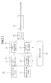
- Fig. 1 is a block diagram schematically illustrating a solar power conversion apparatus according to an embodiment.
- a solar power conversion apparatus 10 includes the first and second solar arrays 11 and 12, a converter 20, a multilevel inverter 30, an AC filter 40, a transformer 50, and a control unit 60.
- the solar arrays 11 and 12 receive light and generate DC power. That is, the solar arrays 11 and 12 may be solar cell arrays in which a plurality of solar cells are arranged to receive sunlight and generate power.
- the converter 20 may include a DC-DC converter or a plurality of DC-DC converters respectively corresponding to the first and second solar arrays 11 and 12.
- the multilevel inverter 30 may include a first multilevel inverter 31 and a second multilevel inverter 32.
- the first and second multilevel inverters 31 and 32 may output five power levels, respectively. If the first and second multilevel inverters 31 and 32 are connected in series, the first and second multilevel inverters 31 and 32 may output nine power levels. That is, the output level of the first and the second multilevel inverters 31 and 32 may depend on the configuration of the multilevel inverter 30.
- first and the second multilevel inverters 31 and 32 are connected in series to generate nine power levels normally, if an error occurs at one of the first and the second multilevel inverters 31 and 32, the other normal multilevel inverter may be operated alone to output five power levels.
- the AC filter 40 insulates the inverter 30 from a power grid.
- the control unit 60 may apply a control signal to the converter and the multilevel inverter 30.
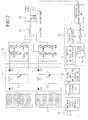
- Fig. 2 is a view illustrating the solar power conversion apparatus in detail according to the embodiment.
- first and second converters 21 and 22 of the AC-DC converter 20 may include diodes D1, D2, D3, and D4, capacitors C1 and C2, inductors L1 and L2, and switching elements T1 and T2, respectively.
- the multilevel inverter 30 may include a plurality of switching elements, an insulated gate bipolar (IGBT), and a bus capacitor limiting a ripple of DC voltage.
- IGBT insulated gate bipolar
- the respective inverters 31 and 32 are connected in series. The detail structure and operation of the multilevel inverter 30 will be described later.
- the control unit 60 may include a converter gating unit 61 and an inverter gating unit 62.
- the converter gating unit 61 applies a gating signal to the converter 20 for maximum power point tracking (MPPT) control.
- MPPT maximum power point tracking
- the inverter gating unit 62 applies a gating signal for controlling the operation of the inverter 30.
- the inverter gating unit 62 may use a pulse width modulation signal (PWM) signal based on a carrier or a space vector PWM signal as a gating signal for controlling the operation of the inverter 30.
- PWM pulse width modulation signal
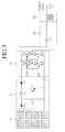
- Fig 3 is a view illustrating one operation of the solar array, the DC-DC converter, and the multilevel inverter according to the embodiment. If one of the inverters 31 and 32 of the solar power conversion apparatus in Fig 2 cannot be operated due to an error, the apparatus may be operated on the condition illustrated in Fig 3 .
- a DC power generated in the solar array 11 is MPPT-controlled by the converter 21 in order to output a maximum output value and is transmitted to the multilevel inverter 31.
- the first converter 21 and the inverter 31 may be controlled by gating signals of the control unit 60, respectively.
- the inverter 31 may output total five power levels according to the gating signal of the control unit 60.
- the inverter 31 may include a plurality of switching elements and two bust capacitors C3 and C4 limiting a ripple of DC voltage. Also as illustrated in Fig. 3 , the switching elements are arranged in two rows each having 4 elements, and clamping diodes may be arranged between the switching elements.
- the switching elements may preferably be insulated gate bipolar transistors (IGBTs).
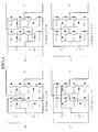
- Fig. 4 is a view illustrating states of the switching elements in the inverter according to each output level of the embodiment.
- the multilevel inverter 31 may output total five power levels such as 2E, E, 0, -E, and -2E.
- '2E' means a voltage of power applied to the inverter 31.
- the switching elements When outputting the power levels such as 2E, E, 0, -E, and -2E, the switching elements may be turned on as shown in the table of Fig. 5 .
- Fig. 5 is a view showing a switching order of the switching elements in the inverter according to the embodiment.
- the switching element may be on. If the state of switching also is 0, the switching element may be off.
- the five power levels may be generated by turning on the switching elements in an order according to a system clock as described above:
- the multilevel inverter 31 includes four pairs of interacting IGBT switches: (TA11+, TA11-), (TA22+, TA22-), (TB11+, TB11-), and (TB22+, TB22-).
- FIG. 4 (a), (b), (c), and (d) are exemplary views illustrating turned-on states of the switching elements according to output levels, wherein (a) shows the output power level 2E, (b) shows the output power level E, (C) shows the output power level -E, and (d) shows the output power level -2E.
- the hybrid diode clamp method is the method that the multilevel inverters are connected in series according to the embodiment.
- total nine power levels such as 4E, 3E, 2E, E, 0, -E, -2E, -3E, and -4E, may be outputted.
- Fig. 6 is a view illustrating an output signal of the solar power conversion apparatus according to the embodiment.
- a signal of a required power level may be extracted from the output signal and then be transmitted to the power grid.
Landscapes
- Engineering & Computer Science (AREA)
- Power Engineering (AREA)
- Inverter Devices (AREA)
- Control Of Electrical Variables (AREA)
- Photovoltaic Devices (AREA)
Applications Claiming Priority (1)
| Application Number | Priority Date | Filing Date | Title |
|---|---|---|---|
| KR1020110055338A KR101906895B1 (ko) | 2011-06-08 | 2011-06-08 | 태양광 전력 변환 장치 |
Publications (2)
| Publication Number | Publication Date |
|---|---|
| EP2533412A2 true EP2533412A2 (de) | 2012-12-12 |
| EP2533412A3 EP2533412A3 (de) | 2017-12-06 |
Family
ID=46261940
Family Applications (1)
| Application Number | Title | Priority Date | Filing Date |
|---|---|---|---|
| EP12170971.1A Withdrawn EP2533412A3 (de) | 2011-06-08 | 2012-06-06 | Solarstromrichter |
Country Status (5)
| Country | Link |
|---|---|
| US (1) | US20120313442A1 (de) |
| EP (1) | EP2533412A3 (de) |
| JP (1) | JP2012257451A (de) |
| KR (1) | KR101906895B1 (de) |
| CN (1) | CN102820800B (de) |
Cited By (5)
| Publication number | Priority date | Publication date | Assignee | Title |
|---|---|---|---|---|
| CZ304509B6 (cs) * | 2013-04-25 | 2014-06-04 | Unites Systems A.S. | Systém pro hospodaření s elektrickou energií vyrobenou fotovoltaickými články |
| WO2014203093A1 (en) * | 2013-06-19 | 2014-12-24 | Sma Solar Technology Ag | Dynamic power distribution in photovoltaic installations |
| US9318974B2 (en) | 2014-03-26 | 2016-04-19 | Solaredge Technologies Ltd. | Multi-level inverter with flying capacitor topology |
| US9941813B2 (en) | 2013-03-14 | 2018-04-10 | Solaredge Technologies Ltd. | High frequency multi-level inverter |
| EP3373433A1 (de) * | 2017-03-07 | 2018-09-12 | ABB Schweiz AG | Eine photovoltaik-stromerzeugungsanlage |
Families Citing this family (12)
| Publication number | Priority date | Publication date | Assignee | Title |
|---|---|---|---|---|
| US9621073B1 (en) * | 2011-08-31 | 2017-04-11 | The Florida State University Research Foundation, Inc. | 1MHz scalable cascaded Z-source inverter using gallium nitride (GAN) device |
| US20140001856A1 (en) * | 2012-06-29 | 2014-01-02 | General Electric Company | Multilevel power converter |
| EP2773036B1 (de) * | 2013-02-27 | 2016-02-24 | Optistring Technologies AB | Verfahren zur Gleichstrom-Wechselstrom-Umwandlung |
| CN103138291A (zh) * | 2013-03-06 | 2013-06-05 | 杨勇 | 一种风力发电智能单相并网控制器 |
| CN103414361A (zh) * | 2013-07-26 | 2013-11-27 | 常州佳讯光电产业发展有限公司 | 一种单机兆瓦级光伏并网逆变器主电路拓扑结构 |
| KR101410508B1 (ko) * | 2014-04-15 | 2014-06-24 | 주식회사 에코스 | 태양광 발전 시스템의 직류 지락 검출 회로 |
| KR101865246B1 (ko) * | 2016-01-13 | 2018-06-07 | 한밭대학교 산학협력단 | 전기자동차용 충방전 장치 |
| US10700526B2 (en) * | 2016-03-14 | 2020-06-30 | Ge Energy Power Conversion Technology Ltd. | Solar power converter with four-wire grid-side connection |
| US10862311B2 (en) | 2016-10-05 | 2020-12-08 | Hitachi, Ltd. | Power conversion device and method for controlling power conversion device |
| CN110739717B (zh) * | 2018-07-19 | 2022-04-08 | 阳光电源股份有限公司 | 一种智能光伏组件及其应用系统 |
| JP2022002427A (ja) * | 2020-06-19 | 2022-01-06 | マツダ株式会社 | 車両用駆動システム |
| KR102493635B1 (ko) * | 2020-12-24 | 2023-01-31 | 엘지전자 주식회사 | 전력 제어 장치 및 그 제어 방법 |
Family Cites Families (35)
| Publication number | Priority date | Publication date | Assignee | Title |
|---|---|---|---|---|
| JP3630854B2 (ja) * | 1996-06-24 | 2005-03-23 | 三洋電機株式会社 | 系統連系電源システム |
| JPH1189242A (ja) * | 1997-09-08 | 1999-03-30 | Yaskawa Electric Corp | 電力変換装置 |
| US6058031A (en) * | 1997-10-23 | 2000-05-02 | General Electric Company | Five level high power motor drive converter and control system |
| JP3406512B2 (ja) * | 1998-03-27 | 2003-05-12 | 株式会社荏原電産 | インバータ装置の制御方法及び制御装置 |
| US6072707A (en) * | 1998-10-23 | 2000-06-06 | Siemens Power Transmission & Distribution, Inc. | High voltage modular inverter |
| JP2000270496A (ja) * | 1999-03-16 | 2000-09-29 | Canon Inc | カプラー装置 |
| US6697271B2 (en) * | 2000-08-16 | 2004-02-24 | Northrop Grumman Corporation | Cascaded multi-level H-bridge drive |
| US7031176B2 (en) * | 2002-07-15 | 2006-04-18 | Koninklijke Philips Electronics N.V. | Inverter |
| US7016697B2 (en) * | 2002-10-29 | 2006-03-21 | Qualcomm Incorporated | Controlling multiple modems in a wireless terminal using dynamically varying modem transmit power limits |
| JP2004327522A (ja) * | 2003-04-22 | 2004-11-18 | Matsushita Electric Ind Co Ltd | 太陽光発電システム |
| US8067855B2 (en) * | 2003-05-06 | 2011-11-29 | Enecsys Limited | Power supply circuits |
| US7050311B2 (en) * | 2003-11-25 | 2006-05-23 | Electric Power Research Institute, Inc. | Multilevel converter based intelligent universal transformer |
| EP1706937B1 (de) * | 2004-01-09 | 2017-03-08 | Philips Lighting Holding B.V. | Gleichstrom-gleichstrom-wandler und dezentralisiertes stromerzeugungssystem mit einem gleichstrom-gleichstrom-wandler |
| EP1964233B8 (de) * | 2005-12-22 | 2016-12-14 | ABB Schweiz AG | System zum produzieren von elektrischem strom aus erneuerbaren quellen und steuerverfahren dafür |
| JP2007325480A (ja) * | 2006-06-05 | 2007-12-13 | National Institute Of Advanced Industrial & Technology | パワー集積化回路 |
| US7808125B1 (en) * | 2006-07-31 | 2010-10-05 | Sustainable Energy Technologies | Scheme for operation of step wave power converter |
| TWI346441B (en) * | 2006-11-10 | 2011-08-01 | Delta Electronics Inc | Three-level ac generating circuit and control method thereof |
| ITVA20080002A1 (it) * | 2008-01-10 | 2009-07-11 | St Microelectronics Srl | Sistema fotovoltaico a pannelli multicellulari con conversione dc-dc multiplata per gruppi di celle in serie di ciascun pannello e struttura di pannello fotovoltaico |
| GB2460072B (en) * | 2008-05-15 | 2013-01-23 | Nujira Ltd | Multiple voltage level supply stage |
| JP5289842B2 (ja) * | 2008-07-04 | 2013-09-11 | 東日本旅客鉄道株式会社 | 試験方法及び試験装置 |
| EP2234237A1 (de) * | 2009-03-26 | 2010-09-29 | ABB Research Ltd. | Verfahren zur Steuerung von Einzelphasen-Gleichstrom-Wechselstrom-Wandler und Wandleranordnung |
| US8184460B2 (en) * | 2009-05-28 | 2012-05-22 | General Electric Company | Solar inverter and control method |
| US20100301676A1 (en) * | 2009-05-28 | 2010-12-02 | General Electric Company | Solar power generation system including weatherable units including photovoltaic modules and isolated power converters |
| US8427010B2 (en) * | 2009-05-29 | 2013-04-23 | General Electric Company | DC-to-AC power conversion system and method |
| JP2011078290A (ja) * | 2009-10-02 | 2011-04-14 | Tabuchi Electric Co Ltd | 電力変換装置および太陽光発電システム |
| US8498137B2 (en) * | 2009-12-11 | 2013-07-30 | Magna International, Inc. | Boost multilevel inverter system |
| US9502904B2 (en) * | 2010-03-23 | 2016-11-22 | Eaton Corporation | Power conversion system and method providing maximum efficiency of power conversion for a photovoltaic system, and photovoltaic system employing a photovoltaic array and an energy storage device |
| CN101950976B (zh) * | 2010-08-25 | 2012-11-28 | 常熟开关制造有限公司(原常熟开关厂) | 一种并网型光伏逆变器的并网运行方法 |
| EP2656496B1 (de) * | 2010-12-22 | 2019-09-11 | GE Energy Power Conversion Technology Limited | Mechanische anordnung einer mehrstufigen stromrichterschaltungsanordnung |
| US20120218795A1 (en) * | 2011-02-28 | 2012-08-30 | Siemens Corporation | Pulse width modulated control for hybrid inverters |
| US9024478B2 (en) * | 2011-03-03 | 2015-05-05 | Massachusetts Institute Of Technology | Photovoltaic energy extraction with multilevel output DC-DC switched capacitor converters |
| US9099914B2 (en) * | 2011-06-29 | 2015-08-04 | Siemens Aktiengesellschaft | Packaging of power supply using modular electronic modules |
| CN102957151A (zh) * | 2011-08-22 | 2013-03-06 | 台达电子企业管理(上海)有限公司 | 一种用于可再生能源系统的功率补偿装置及其方法 |
| IN2014CN04730A (de) * | 2011-11-30 | 2015-09-18 | Panasonic Corp | |
| US9225262B2 (en) * | 2012-06-29 | 2015-12-29 | Eaton Corporation | Multi-level inverter apparatus and methods using variable overcurrent response |
-
2011
- 2011-06-08 KR KR1020110055338A patent/KR101906895B1/ko active IP Right Grant
-
2012
- 2012-06-05 US US13/489,164 patent/US20120313442A1/en not_active Abandoned
- 2012-06-06 EP EP12170971.1A patent/EP2533412A3/de not_active Withdrawn
- 2012-06-08 CN CN201210189259.6A patent/CN102820800B/zh not_active Expired - Fee Related
- 2012-06-08 JP JP2012130982A patent/JP2012257451A/ja active Pending
Non-Patent Citations (1)
| Title |
|---|
| None |
Cited By (20)
| Publication number | Priority date | Publication date | Assignee | Title |
|---|---|---|---|---|
| US11742777B2 (en) | 2013-03-14 | 2023-08-29 | Solaredge Technologies Ltd. | High frequency multi-level inverter |
| US9941813B2 (en) | 2013-03-14 | 2018-04-10 | Solaredge Technologies Ltd. | High frequency multi-level inverter |
| US11545912B2 (en) | 2013-03-14 | 2023-01-03 | Solaredge Technologies Ltd. | High frequency multi-level inverter |
| CZ304509B6 (cs) * | 2013-04-25 | 2014-06-04 | Unites Systems A.S. | Systém pro hospodaření s elektrickou energií vyrobenou fotovoltaickými články |
| WO2014203093A1 (en) * | 2013-06-19 | 2014-12-24 | Sma Solar Technology Ag | Dynamic power distribution in photovoltaic installations |
| CN105164886A (zh) * | 2013-06-19 | 2015-12-16 | 艾思玛太阳能技术股份公司 | 光伏安装装置中的动态功率分配 |
| US11296590B2 (en) | 2014-03-26 | 2022-04-05 | Solaredge Technologies Ltd. | Multi-level inverter |
| US10886831B2 (en) | 2014-03-26 | 2021-01-05 | Solaredge Technologies Ltd. | Multi-level inverter |
| US10404154B2 (en) | 2014-03-26 | 2019-09-03 | Solaredge Technologies Ltd | Multi-level inverter with flying capacitor topology |
| US10680506B2 (en) | 2014-03-26 | 2020-06-09 | Solaredge Technologies Ltd. | Multi-level inverter |
| US10680505B2 (en) | 2014-03-26 | 2020-06-09 | Solaredge Technologies Ltd. | Multi-level inverter |
| US10700588B2 (en) | 2014-03-26 | 2020-06-30 | Solaredge Technologies Ltd. | Multi-level inverter |
| US10886832B2 (en) | 2014-03-26 | 2021-01-05 | Solaredge Technologies Ltd. | Multi-level inverter |
| US10153685B2 (en) | 2014-03-26 | 2018-12-11 | Solaredge Technologies Ltd. | Power ripple compensation |
| US11855552B2 (en) | 2014-03-26 | 2023-12-26 | Solaredge Technologies Ltd. | Multi-level inverter |
| US9318974B2 (en) | 2014-03-26 | 2016-04-19 | Solaredge Technologies Ltd. | Multi-level inverter with flying capacitor topology |
| US11632058B2 (en) | 2014-03-26 | 2023-04-18 | Solaredge Technologies Ltd. | Multi-level inverter |
| EP3373433A1 (de) * | 2017-03-07 | 2018-09-12 | ABB Schweiz AG | Eine photovoltaik-stromerzeugungsanlage |
| WO2018162215A1 (en) * | 2017-03-07 | 2018-09-13 | Abb Schweiz Ag | A photovoltaic power plant system |
| US11228178B2 (en) | 2017-03-07 | 2022-01-18 | Marici Holdings The Netherlands B.V. | Photovoltaic power plant system |
Also Published As
| Publication number | Publication date |
|---|---|
| US20120313442A1 (en) | 2012-12-13 |
| KR20120136245A (ko) | 2012-12-18 |
| EP2533412A3 (de) | 2017-12-06 |
| CN102820800B (zh) | 2016-03-09 |
| KR101906895B1 (ko) | 2018-10-11 |
| CN102820800A (zh) | 2012-12-12 |
| JP2012257451A (ja) | 2012-12-27 |
Similar Documents
| Publication | Publication Date | Title |
|---|---|---|
| EP2533412A2 (de) | Solarstromrichter | |
| Gupta et al. | A multilevel Voltage Source Inverter (VSI) to maximize the number of levels in output waveform | |
| US10978948B2 (en) | Interleaved multi-channel, multi-level, multi-quadrant DC-DC converters | |
| EP2256918B1 (de) | Gleichstrom-Wechselstrom-Leistungswandlungssystem | |
| US8144491B2 (en) | Cascaded flying capacitor modular high voltage inverters | |
| ES2654245T3 (es) | Sistema de conversión de energía eólica | |
| EP2961057A1 (de) | Spannungsquellenwandler und Steuerung dafür | |
| US9344010B2 (en) | Power electronic converter | |
| US20160218637A1 (en) | A new four-level converter cell topology for cascaded modular multilevel converters | |
| CN102075104A (zh) | 具有多个输入端子和两个输出端子的转换装置和使用其的光伏系统 | |
| WO2013135277A1 (en) | A clamped modular power converter | |
| US20190148947A1 (en) | System and device for exporting power, and method of configuring thereof | |
| EP2747268B1 (de) | Spannungsgeführter und stromgeregelter Multilevelumrichter | |
| CA2894127C (en) | Switching stage, energy conversion circuit, and conversion stage for wind turbines comprising the energy conversion circuit | |
| Diouri et al. | Design and simulation of a novel cascaded transformer multilevel inverter topology for photovoltaic system | |
| Sandoval et al. | A new delta inverter system for grid integration of large scale photovoltaic power plants | |
| EP3176941B1 (de) | Verfahren zur steuerung des neutralpunktpotenzials für einphasige npc-wechselrichter | |
| Thakre et al. | Modelling and design of new multilevel inverter for renewable energy systems with less number of unidirectional switches | |
| US11601046B2 (en) | Three-phase double t-type four-level rectifier | |
| Sandeep et al. | Switched-capacitor-based three-phase five-level inverter topology with reduced components | |
| Sundaravel et al. | A Modified Cascaded H-Bridge Multilevel Inverter topology with Reduced Number of Power Electronic Switching Components | |
| KR101718303B1 (ko) | 단일 입력 전압원과 배터리 직병렬 결합을 이용한 멀티레벨 인버터 | |
| Varna et al. | Seven level inverter with nearest level control | |
| US20210143753A1 (en) | Multiphase Current-Fed Modular Multilevel Converter | |
| Fatima et al. | Design of New Cascaded Multilevel Inverter with Symmetrical DC-voltage Source |
Legal Events
| Date | Code | Title | Description |
|---|---|---|---|
| PUAI | Public reference made under article 153(3) epc to a published international application that has entered the european phase |
Free format text: ORIGINAL CODE: 0009012 |
|
| AK | Designated contracting states |
Kind code of ref document: A2 Designated state(s): AL AT BE BG CH CY CZ DE DK EE ES FI FR GB GR HR HU IE IS IT LI LT LU LV MC MK MT NL NO PL PT RO RS SE SI SK SM TR |
|
| AX | Request for extension of the european patent |
Extension state: BA ME |
|
| PUAL | Search report despatched |
Free format text: ORIGINAL CODE: 0009013 |
|
| AK | Designated contracting states |
Kind code of ref document: A3 Designated state(s): AL AT BE BG CH CY CZ DE DK EE ES FI FR GB GR HR HU IE IS IT LI LT LU LV MC MK MT NL NO PL PT RO RS SE SI SK SM TR |
|
| AX | Request for extension of the european patent |
Extension state: BA ME |
|
| RIC1 | Information provided on ipc code assigned before grant |
Ipc: H02J 3/38 20060101ALI20171030BHEP Ipc: H02M 7/483 20070101AFI20171030BHEP |
|
| 17P | Request for examination filed |
Effective date: 20180530 |
|
| RBV | Designated contracting states (corrected) |
Designated state(s): AL AT BE BG CH CY CZ DE DK EE ES FI FR GB GR HR HU IE IS IT LI LT LU LV MC MK MT NL NO PL PT RO RS SE SI SK SM TR |
|
| 17Q | First examination report despatched |
Effective date: 20200731 |
|
| STAA | Information on the status of an ep patent application or granted ep patent |
Free format text: STATUS: THE APPLICATION HAS BEEN WITHDRAWN |
|
| 18W | Application withdrawn |
Effective date: 20201201 |