EP2533377A1 - Electric safety plug - Google Patents
Electric safety plug Download PDFInfo
- Publication number
- EP2533377A1 EP2533377A1 EP12153971A EP12153971A EP2533377A1 EP 2533377 A1 EP2533377 A1 EP 2533377A1 EP 12153971 A EP12153971 A EP 12153971A EP 12153971 A EP12153971 A EP 12153971A EP 2533377 A1 EP2533377 A1 EP 2533377A1
- Authority
- EP
- European Patent Office
- Prior art keywords
- base
- electrical
- protective contact
- electrical safety
- contact
- Prior art date
- Legal status (The legal status is an assumption and is not a legal conclusion. Google has not performed a legal analysis and makes no representation as to the accuracy of the status listed.)
- Withdrawn
Links
Images


Classifications
-
- H—ELECTRICITY
- H01—ELECTRIC ELEMENTS
- H01R—ELECTRICALLY-CONDUCTIVE CONNECTIONS; STRUCTURAL ASSOCIATIONS OF A PLURALITY OF MUTUALLY-INSULATED ELECTRICAL CONNECTING ELEMENTS; COUPLING DEVICES; CURRENT COLLECTORS
- H01R24/00—Two-part coupling devices, or either of their cooperating parts, characterised by their overall structure
- H01R24/76—Two-part coupling devices, or either of their cooperating parts, characterised by their overall structure with sockets, clips or analogous contacts and secured to apparatus or structure, e.g. to a wall
- H01R24/78—Two-part coupling devices, or either of their cooperating parts, characterised by their overall structure with sockets, clips or analogous contacts and secured to apparatus or structure, e.g. to a wall with additional earth or shield contacts
-
- H—ELECTRICITY
- H01—ELECTRIC ELEMENTS
- H01R—ELECTRICALLY-CONDUCTIVE CONNECTIONS; STRUCTURAL ASSOCIATIONS OF A PLURALITY OF MUTUALLY-INSULATED ELECTRICAL CONNECTING ELEMENTS; COUPLING DEVICES; CURRENT COLLECTORS
- H01R13/00—Details of coupling devices of the kinds covered by groups H01R12/70 or H01R24/00 - H01R33/00
- H01R13/648—Protective earth or shield arrangements on coupling devices, e.g. anti-static shielding
- H01R13/655—Protective earth or shield arrangements on coupling devices, e.g. anti-static shielding with earth brace
-
- H—ELECTRICITY
- H01—ELECTRIC ELEMENTS
- H01R—ELECTRICALLY-CONDUCTIVE CONNECTIONS; STRUCTURAL ASSOCIATIONS OF A PLURALITY OF MUTUALLY-INSULATED ELECTRICAL CONNECTING ELEMENTS; COUPLING DEVICES; CURRENT COLLECTORS
- H01R2103/00—Two poles
Definitions
- the present invention is based on a designed according to the preamble of the main claim electrical safety socket.
- Such electrical socket outlets are particularly intended to produce an easily re-separable electrically conductive connection to a consumer as needed via a suitably trained plug-in safety plug and optionally an electrical line connected thereto.
- a variety of such socket outlets are already known in the market.
- Schuko sockets which have a centrally disposed earthing contact spring on their earthing strap in order to record a suitably trained, having a center contact having protective contact plug. It is known to attach to the base web of the grounding strap an additional protective contact spring, but this is associated with a corresponding manufacturing effort.
- This electrical safety socket has a contact parts for contacting the plug part and the electrical lines to be connected of the power supply network exhibiting base part on which a socket center piece can be fastened.
- the electrical safety socket has a made of flat material, two interconnected via a base bar protective contact legs, earthing strap.
- the present invention has for its object to provide an electrical safety socket, in which the protective contact spring in one piece is made of the flat material used for the production of the grounding strap.
- modules of such trained Schuko socket can be found in a modular manner in different program lines use.
- such an electrical socket outlet consists mainly of one, the grounding strap 1 and the necessary for contacting the pins and the electrical leads contact parts 2 receiving base part 3, to which a socket center piece 4 can be fastened.
- a designed as a support ring 5 carrier is provided to ensure a reliable attachment of the socket.
- the base part 3 consists of a base made of plastic base 3a and base top 3b.
- the grounding strap 1 is made in one piece from flat material and has two interconnected via a base web 6 outer protective contact legs 7 and a centrally arranged protective contact spring 8.
- the protective contact spring 8 is integrally formed on the grounding strap 1 via a tab 9 projecting laterally from the base web 6.
- the protective contact spring 8 consists of two U-shaped angled from a base 10 contact arms 11, wherein the protective contact spring 8 - as in particular from FIG. 3 emerges - is bent by means of the tab 9 in a centrally located in the base web 6 free space 12.
- the ground contact spring 8 In order for the grounding pin (center contact) of the grounding plug to be inserted into the grounded socket with particular ease, the free ends of the two contact arms 11, the ground contact spring 8 have a tulip-shaped insertion aid 13.
- the two free end regions 14 of the two protective contact legs 7 each have a U-shaped contour, so that a matched to the safety plug spring characteristic is realized.
- the grounding strap 1 is to be provided with a clamping device 15, so that in a simple manner the necessary for the function of electrical line can be connected.
- a screw is installed for connecting an electrical line, but just as well, a spring clip can be provided.
- the grounding strap 1 is fixed via a crimping bushing 16 on the base part 3 or base part 3a.
- the Bördelbuchse 16 has an internal thread for connection to a screw 17.
- the screw 17 is intended to fix the socket center 4 on the base part 3. It is an eccentric positioning of Bördelbuchse 16 and screw 17 is provided so that an assembly 18 can be easily accommodated for the realization of an increased contact protection when needed.
- an assembly 18 is provided for the realization of an increased contact protection.
- This assembly 18 can be installed as needed or omitted for lower requirements.
- An assembly 18 designed in this way can be used unchanged in a multitude of program lines, which ensures modular use.
- the pedestal base 3a, the carrier designed as a support ring 5 and the fastening claw 19 to be mounted on the base part 3, together with its fastening screws 20, can also be used without modification in a multitude of program lines.
- FIG. 1 and FIG. 6 shows, both with a grounded socket with and without hinged lid 21 possible. In the present case, the according to FIG. 1 and FIG.
- FIG. 6 designed earthed sockets intended to be able to record as contact partners in each case two differently designed safety plug S1, S2.
- FIG. 4 and FIG. 5 shows, it is on the one hand to a first earthing contact plug S1 with externally arranged protective contacts and on the other hand to a second safety plug S2 with a centrally arranged protective contact pin.
Landscapes
- Details Of Connecting Devices For Male And Female Coupling (AREA)
Abstract
Description
Die vorliegende Erfindung geht von einer gemäß Oberbegriff des Hauptanspruches konzipierten elektrischen Schutzkontaktsteckdose aus.The present invention is based on a designed according to the preamble of the main claim electrical safety socket.
Derartige elektrische Schutzkontaktsteckdosen sind insbesondere dafür vorgesehen, je nach Bedarf über einen entsprechend ausgebildeten einsteckbaren Schutzkontaktstecker und gegebenenfalls eine daran angeschlossene elektrische Leitung eine leicht wieder trennbare elektrisch leitende Verbindung zu einem Verbraucher herzustellen. Eine Vielzahl solcher Schutzkontaktsteckdosen sind bereits im Markt bekannt. Zudem sind Schutzkontaktsteckdosen bekannt, welche an ihrem Erdungsbügel eine mittig angeordnete Schutzkontaktfeder aufweisen, um einen entsprechend ausgebildeten, einen Mittenkontakt aufweisenden Schutzkontaktstecker aufnehmen zu können. Bekannt ist dabei, an dem Basissteg des Erdungsbügels eine zusätzliche Schutzkontaktfeder zu befestigen, was jedoch mit einem entsprechenden fertigungstechnischen Aufwand verbunden ist.Such electrical socket outlets are particularly intended to produce an easily re-separable electrically conductive connection to a consumer as needed via a suitably trained plug-in safety plug and optionally an electrical line connected thereto. A variety of such socket outlets are already known in the market. In addition, Schuko sockets are known which have a centrally disposed earthing contact spring on their earthing strap in order to record a suitably trained, having a center contact having protective contact plug. It is known to attach to the base web of the grounding strap an additional protective contact spring, but this is associated with a corresponding manufacturing effort.
Eine dem Oberbegriff des Hauptanspruches entsprechende elektrische Schutzkontaktsteckdose ist durch die
Der vorliegenden Erfindung liegt deshalb die Aufgabe zugrunde, eine elektrische Schutzkontaktsteckdose zu schaffen, bei der die Schutzkontaktfeder einstückig aus dem für die Herstellung des Erdungsbügels verwendeten Flachmaterial hergestellt ist.Therefore, the present invention has for its object to provide an electrical safety socket, in which the protective contact spring in one piece is made of the flat material used for the production of the grounding strap.
Diese Aufgabe wird durch die im Hauptanspruch angegebenen Merkmale gelöst.This object is achieved by the features specified in the main claim.
Bei einer solchermaßen ausgebildeten elektrischen Schutzkontaktsteckdose ist besonders vorteilhaft, dass sowohl Schutzkontaktstecker mit außen angeordneten Schutzkontakten, als auch Schutzkontaktstecker mit einem mittig angeordneten Schutzkontaktstift aufgenommen bzw. kontaktiert werden können.In such a trained electrical safety socket is particularly advantageous that both safety plug with externally arranged protective contacts, as well as grounding plug can be added or contacted with a centrally arranged protective contact pin.
Weiterhin ist besonders vorteilhaft, dass die Baugruppen einer derart ausgebildeten Schutzkontaktsteckdose modulartig in verschiedenen Programmlinien Verwendung finden können.Furthermore, it is particularly advantageous that the modules of such trained Schuko socket can be found in a modular manner in different program lines use.
Weitere vorteilhafte Ausgestaltungen sind in den Unteransprüchen angegeben. Anhand zweier in den Zeichnungen näher dargestellter Ausführungsbeispiele sei der erfindungsgemäße Gegenstand näher erläutert. Dabei zeigt:
- Fig. 1:
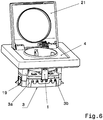
- räumlich ein erstes Ausführungsbeispiel einer elektrischen Schutzkontaktsteckdose in Explosionsdarstellung;
- Fig. 2:
- den Erdungsbügel mit angeformter Schutzkontaktfeder räumlich, wobei die Schutzkontaktfeder in ihrer Ausgangsposition dargestellt ist;
- Fig. 3:
- den Erdungsbügel mit angeformter Schutzkontaktfeder räumlich, wobei die Schutzkontaktfeder in ihrer Kontaktposition dargestellt ist;
- Fig. 4:
- einen Schutzkontaktstecker mit außen angeordneten Schutzkontakten räumlich;
- Fig. 5:
- einen Schutzkontaktstecker mit einem mittig angeordneten Schutzkontaktstift räumlich;
- Fig. 6:
- räumlich ein zweites Ausführungsbeispiel einer elektrischen Schutzkontaktsteckdose mit Klappdeckel im Zusammenbau.
- Fig. 1:
- spatially a first embodiment of an electrical safety socket in an exploded view;
- Fig. 2:
- the earthing bar with molded protective contact spring spatially, wherein the protective contact spring is shown in its initial position;
- 3:
- the earthing strap with molded protective contact spring spatially, wherein the protective contact spring is shown in its contact position;
- 4:
- a safety plug with externally arranged protective contacts spatially;
- Fig. 5:
- a safety plug with a centrally arranged ground contact pin spatially;
- Fig. 6:
- spatially a second embodiment of an electrical safety socket with hinged lid in the assembly.
Wie aus der Zeichnung hervorgeht, besteht eine solche elektrische Schutzkontaktsteckdose hauptsächlich aus einem, den Erdungsbügel 1 und die zur Kontaktierung der Steckerstifte, sowie der elektrischen Leitungen notwendigen Kontaktteile 2 aufnehmenden Sockelteil 3, an welchem ein Steckdosenzentralstück 4 befestigbar ist. Außerdem ist ein als Tragring 5 ausgeführter Träger vorgesehen, um eine zuverlässige Befestigung der Schutzkontaktsteckdose zu gewährleisten. Das Sockelteil 3 besteht aus einem aus Kunststoff hergestellten Sockelunterteil 3a und Sockeloberteil 3b.As is apparent from the drawing, such an electrical socket outlet consists mainly of one, the
Wie des Weiteren aus den Figuren hervorgeht, ist der Erdungsbügel 1 einstückig aus Flachmaterial hergestellt und weist zwei über einen Basissteg 6 miteinander verbundene äußere Schutzkontaktschenkel 7 sowie eine mittig angeordnete Schutzkontaktfeder 8 auf. Die Schutzkontaktfeder 8 ist über eine seitlich vom Basissteg 6 abstehende Lasche 9 an den Erdungsbügel 1 angeformt. Zudem besteht die Schutzkontaktfeder 8 aus zwei U-förmig von einer Basis 10 abgewinkelten Kontaktarmen 11, wobei die Schutzkontaktfeder 8 - wie insbesondere aus
Der Erdungsbügel 1 ist mit einer Klemmeinrichtung 15 zu versehen, damit auf einfache Art und Weise die zur Funktion notwendige elektrische Leitung angeschlossen werden kann. Bei dem vorliegenden Ausführungsbeispiel ist zum Anschluss einer elektrischen Leitung eine Schraubklemme verbaut, genauso gut kann jedoch auch eine Federklemme vorgesehen werden. Der Erdungsbügel 1 ist über eine Bördelbuchse 16 am Sockelteil 3 bzw. Sockelunterteil 3a festgelegt. Die Bördelbuchse 16 weist ein Innengewinde zur Verbindung mit einer Schraube 17 auf. Die Schraube 17 ist dafür vorgesehen, um das Steckdosenzentralstück 4 am Sockelteil 3 festzulegen. Es ist eine außermittige Positionierung von Bördelbuchse 16 und Schraube 17 vorgesehen, damit eine Baugruppe 18 zur Realisierung eines erhöhten Berührungsschutzes bei Bedarf problemlos untergebracht werden kann.The
Wie insbesondere aus
Claims (6)
Applications Claiming Priority (1)
| Application Number | Priority Date | Filing Date | Title |
|---|---|---|---|
| DE102011050845A DE102011050845B3 (en) | 2011-06-06 | 2011-06-06 | Method for producing a protective contact clip for a grounded socket and a grounded socket with it |
Publications (1)
| Publication Number | Publication Date |
|---|---|
| EP2533377A1 true EP2533377A1 (en) | 2012-12-12 |
Family
ID=45554578
Family Applications (1)
| Application Number | Title | Priority Date | Filing Date |
|---|---|---|---|
| EP12153971A Withdrawn EP2533377A1 (en) | 2011-06-06 | 2012-02-06 | Electric safety plug |
Country Status (2)
| Country | Link |
|---|---|
| EP (1) | EP2533377A1 (en) |
| DE (1) | DE102011050845B3 (en) |
Cited By (2)
| Publication number | Priority date | Publication date | Assignee | Title |
|---|---|---|---|---|
| ES2569744A1 (en) * | 2015-12-07 | 2016-05-12 | Carlos González Bravo | Hidden security base for electric plug (Machine-translation by Google Translate, not legally binding) |
| CN112290267A (en) * | 2020-10-26 | 2021-01-29 | 宁波公牛电器有限公司 | Plug bush assembly and socket |
Citations (4)
| Publication number | Priority date | Publication date | Assignee | Title |
|---|---|---|---|---|
| DE8303884U1 (en) * | 1983-02-09 | 1986-04-30 | Siemens AG, 1000 Berlin und 8000 München | Grounding bracket for a plug |
| DE29823573U1 (en) * | 1998-08-03 | 1999-08-12 | Siemens AG, 80333 München | socket |
| EP1489703A1 (en) * | 2003-06-19 | 2004-12-22 | Ensto Busch-Jaeger Oy | 2-gang socket-outlet |
| DE102008023938A1 (en) | 2008-05-16 | 2009-11-19 | Emitec Gesellschaft Für Emissionstechnologie Mbh | Aqueous solution e.g. urea-water-solution, evaporation unit for use in exhaust gas system of motor vehicle, has heat layer formed outside thermal conductive layer and connected in material fit to thermal conductive layer |
Family Cites Families (5)
| Publication number | Priority date | Publication date | Assignee | Title |
|---|---|---|---|---|
| DE1658359U (en) * | 1952-09-05 | 1953-07-02 | Stotz Kontakt Gmbh | TWO-POLE CONNECTOR WITH A LATERAL PROTECTIVE CONTACT BRACKET ARRANGED IN THE SOCKET. |
| DE1893577U (en) * | 1964-03-21 | 1964-05-27 | Jung Albrecht Fa | PROTECTIVE CONTACT SOCKET WITH PROTECTIVE CONTACT BRACKET ON THE FRONT OF THE BASE. |
| DE8013677U1 (en) * | 1980-05-21 | 1981-11-05 | Selter & Kiebeler GmbH, 5800 Hagen | Safety plug |
| IT250397Y1 (en) * | 2000-12-19 | 2003-09-10 | Vimar S R L Ora Vimar S P A | MULTIPLE MOBILE POWER SOCKET |
| DE102008023983B4 (en) * | 2008-05-16 | 2013-02-28 | Berker Gmbh & Co. Kg | Electrical installation device |
-
2011
- 2011-06-06 DE DE102011050845A patent/DE102011050845B3/en not_active Expired - Fee Related
-
2012
- 2012-02-06 EP EP12153971A patent/EP2533377A1/en not_active Withdrawn
Patent Citations (4)
| Publication number | Priority date | Publication date | Assignee | Title |
|---|---|---|---|---|
| DE8303884U1 (en) * | 1983-02-09 | 1986-04-30 | Siemens AG, 1000 Berlin und 8000 München | Grounding bracket for a plug |
| DE29823573U1 (en) * | 1998-08-03 | 1999-08-12 | Siemens AG, 80333 München | socket |
| EP1489703A1 (en) * | 2003-06-19 | 2004-12-22 | Ensto Busch-Jaeger Oy | 2-gang socket-outlet |
| DE102008023938A1 (en) | 2008-05-16 | 2009-11-19 | Emitec Gesellschaft Für Emissionstechnologie Mbh | Aqueous solution e.g. urea-water-solution, evaporation unit for use in exhaust gas system of motor vehicle, has heat layer formed outside thermal conductive layer and connected in material fit to thermal conductive layer |
Cited By (3)
| Publication number | Priority date | Publication date | Assignee | Title |
|---|---|---|---|---|
| ES2569744A1 (en) * | 2015-12-07 | 2016-05-12 | Carlos González Bravo | Hidden security base for electric plug (Machine-translation by Google Translate, not legally binding) |
| CN112290267A (en) * | 2020-10-26 | 2021-01-29 | 宁波公牛电器有限公司 | Plug bush assembly and socket |
| CN112290267B (en) * | 2020-10-26 | 2022-10-04 | 宁波公牛电器有限公司 | Plug bush assembly and socket |
Also Published As
| Publication number | Publication date |
|---|---|
| DE102011050845B3 (en) | 2012-10-04 |
Similar Documents
| Publication | Publication Date | Title |
|---|---|---|
| EP2593991B1 (en) | Electrical contact part | |
| DE102013110548A1 (en) | Connector part with a resistance coding | |
| DE202006006659U1 (en) | Structural assembly for industrial automation device, has housing half provided with metallic fixing devices for fixing and contacting printed circuit board and coupling part and including connector in base area | |
| DE202018006882U1 (en) | Assembly for a connector part with a contact insert and a grounding element | |
| EP2107648A1 (en) | Connector with a shielding-screen support | |
| EP1691454B1 (en) | Electrical connector with locking hooks | |
| DE19547557A1 (en) | Electric terminals with pluggable transverse bridges | |
| EP2297820B1 (en) | Metal protective ground conductor connection device | |
| DE202012010451U1 (en) | Connector with insulating part | |
| EP3066723B1 (en) | Test cable and socket adapter for a test cable | |
| DE102011050845B3 (en) | Method for producing a protective contact clip for a grounded socket and a grounded socket with it | |
| DE102012020219A1 (en) | Device i.e. supply and connecting terminal, for contacting e.g. electric conductors in lamp, has housing front and rear parts formed as unit, and electrical interconnect components arranged in unit to balance displacement of contact points | |
| EP3412965B1 (en) | Integrated lights | |
| EP1901398B1 (en) | Connector piece for creating an electric contact | |
| WO2013034443A1 (en) | Electric connector with contact protection | |
| EP1593979A2 (en) | Support housing for a meter in a cabinet for meters | |
| DE202015105021U1 (en) | Connection housing with a connecting device for conductors | |
| DE102015110171B4 (en) | ELECTRICAL FUSE FOR A VEHICLE AND EQUIPPED ELECTRICAL POWER DISTRIBUTOR | |
| DE3016856C2 (en) | Table socket | |
| EP2856515B1 (en) | Electrical connection and junction box for a solar cell module | |
| DE102013013715B4 (en) | Electrical contact arrangement and method for producing such an electrical contact arrangement | |
| EP3304651B1 (en) | Electrical plug connector | |
| EP2846405B1 (en) | Contact support assembly | |
| DE202018104755U1 (en) | Socket for receiving an electrical component | |
| EP2363924A1 (en) | Device for connecting a cable with an electric component element in a housing |
Legal Events
| Date | Code | Title | Description |
|---|---|---|---|
| PUAI | Public reference made under article 153(3) epc to a published international application that has entered the european phase |
Free format text: ORIGINAL CODE: 0009012 |
|
| AK | Designated contracting states |
Kind code of ref document: A1 Designated state(s): AL AT BE BG CH CY CZ DE DK EE ES FI FR GB GR HR HU IE IS IT LI LT LU LV MC MK MT NL NO PL PT RO RS SE SI SK SM TR |
|
| AX | Request for extension of the european patent |
Extension state: BA ME |
|
| 17P | Request for examination filed |
Effective date: 20130108 |
|
| 17Q | First examination report despatched |
Effective date: 20150814 |
|
| GRAP | Despatch of communication of intention to grant a patent |
Free format text: ORIGINAL CODE: EPIDOSNIGR1 |
|
| INTG | Intention to grant announced |
Effective date: 20171207 |
|
| STAA | Information on the status of an ep patent application or granted ep patent |
Free format text: STATUS: THE APPLICATION IS DEEMED TO BE WITHDRAWN |
|
| 18D | Application deemed to be withdrawn |
Effective date: 20180418 |