EP2532874B1 - Filterelement und Kraftstofffilter - Google Patents
Filterelement und Kraftstofffilter Download PDFInfo
- Publication number
- EP2532874B1 EP2532874B1 EP12180355.5A EP12180355A EP2532874B1 EP 2532874 B1 EP2532874 B1 EP 2532874B1 EP 12180355 A EP12180355 A EP 12180355A EP 2532874 B1 EP2532874 B1 EP 2532874B1
- Authority
- EP
- European Patent Office
- Prior art keywords
- filter
- fuel
- heating element
- housing
- filter element
- Prior art date
- Legal status (The legal status is an assumption and is not a legal conclusion. Google has not performed a legal analysis and makes no representation as to the accuracy of the status listed.)
- Active
Links
Images
Classifications
-
- F—MECHANICAL ENGINEERING; LIGHTING; HEATING; WEAPONS; BLASTING
- F02—COMBUSTION ENGINES; HOT-GAS OR COMBUSTION-PRODUCT ENGINE PLANTS
- F02M—SUPPLYING COMBUSTION ENGINES IN GENERAL WITH COMBUSTIBLE MIXTURES OR CONSTITUENTS THEREOF
- F02M37/00—Apparatus or systems for feeding liquid fuel from storage containers to carburettors or fuel-injection apparatus; Arrangements for purifying liquid fuel specially adapted for, or arranged on, internal-combustion engines
- F02M37/22—Arrangements for purifying liquid fuel specially adapted for, or arranged on, internal-combustion engines, e.g. arrangements in the feeding system
- F02M37/32—Arrangements for purifying liquid fuel specially adapted for, or arranged on, internal-combustion engines, e.g. arrangements in the feeding system characterised by filters or filter arrangements
-
- B—PERFORMING OPERATIONS; TRANSPORTING
- B01—PHYSICAL OR CHEMICAL PROCESSES OR APPARATUS IN GENERAL
- B01D—SEPARATION
- B01D27/00—Cartridge filters of the throw-away type
- B01D27/04—Cartridge filters of the throw-away type with cartridges made of a piece of unitary material, e.g. filter paper
- B01D27/06—Cartridge filters of the throw-away type with cartridges made of a piece of unitary material, e.g. filter paper with corrugated, folded or wound material
-
- B—PERFORMING OPERATIONS; TRANSPORTING
- B01—PHYSICAL OR CHEMICAL PROCESSES OR APPARATUS IN GENERAL
- B01D—SEPARATION
- B01D27/00—Cartridge filters of the throw-away type
- B01D27/08—Construction of the casing
-
- B—PERFORMING OPERATIONS; TRANSPORTING
- B01—PHYSICAL OR CHEMICAL PROCESSES OR APPARATUS IN GENERAL
- B01D—SEPARATION
- B01D29/00—Filters with filtering elements stationary during filtration, e.g. pressure or suction filters, not covered by groups B01D24/00 - B01D27/00; Filtering elements therefor
- B01D29/11—Filters with filtering elements stationary during filtration, e.g. pressure or suction filters, not covered by groups B01D24/00 - B01D27/00; Filtering elements therefor with bag, cage, hose, tube, sleeve or like filtering elements
- B01D29/31—Self-supporting filtering elements
- B01D29/33—Self-supporting filtering elements arranged for inward flow filtration
- B01D29/333—Self-supporting filtering elements arranged for inward flow filtration with corrugated, folded filtering elements
-
- B—PERFORMING OPERATIONS; TRANSPORTING
- B01—PHYSICAL OR CHEMICAL PROCESSES OR APPARATUS IN GENERAL
- B01D—SEPARATION
- B01D29/00—Filters with filtering elements stationary during filtration, e.g. pressure or suction filters, not covered by groups B01D24/00 - B01D27/00; Filtering elements therefor
- B01D29/60—Filters with filtering elements stationary during filtration, e.g. pressure or suction filters, not covered by groups B01D24/00 - B01D27/00; Filtering elements therefor integrally combined with devices for controlling the filtration
- B01D29/606—Filters with filtering elements stationary during filtration, e.g. pressure or suction filters, not covered by groups B01D24/00 - B01D27/00; Filtering elements therefor integrally combined with devices for controlling the filtration by pressure measuring
-
- B—PERFORMING OPERATIONS; TRANSPORTING
- B01—PHYSICAL OR CHEMICAL PROCESSES OR APPARATUS IN GENERAL
- B01D—SEPARATION
- B01D35/00—Filtering devices having features not specifically covered by groups B01D24/00 - B01D33/00, or for applications not specifically covered by groups B01D24/00 - B01D33/00; Auxiliary devices for filtration; Filter housing constructions
- B01D35/005—Filters specially adapted for use in internal-combustion engine lubrication or fuel systems
-
- B—PERFORMING OPERATIONS; TRANSPORTING
- B01—PHYSICAL OR CHEMICAL PROCESSES OR APPARATUS IN GENERAL
- B01D—SEPARATION
- B01D35/00—Filtering devices having features not specifically covered by groups B01D24/00 - B01D33/00, or for applications not specifically covered by groups B01D24/00 - B01D33/00; Auxiliary devices for filtration; Filter housing constructions
- B01D35/18—Heating or cooling the filters
-
- F—MECHANICAL ENGINEERING; LIGHTING; HEATING; WEAPONS; BLASTING
- F02—COMBUSTION ENGINES; HOT-GAS OR COMBUSTION-PRODUCT ENGINE PLANTS
- F02M—SUPPLYING COMBUSTION ENGINES IN GENERAL WITH COMBUSTIBLE MIXTURES OR CONSTITUENTS THEREOF
- F02M31/00—Apparatus for thermally treating combustion-air, fuel, or fuel-air mixture
- F02M31/02—Apparatus for thermally treating combustion-air, fuel, or fuel-air mixture for heating
- F02M31/12—Apparatus for thermally treating combustion-air, fuel, or fuel-air mixture for heating electrically
- F02M31/125—Fuel
-
- F—MECHANICAL ENGINEERING; LIGHTING; HEATING; WEAPONS; BLASTING
- F02—COMBUSTION ENGINES; HOT-GAS OR COMBUSTION-PRODUCT ENGINE PLANTS
- F02M—SUPPLYING COMBUSTION ENGINES IN GENERAL WITH COMBUSTIBLE MIXTURES OR CONSTITUENTS THEREOF
- F02M37/00—Apparatus or systems for feeding liquid fuel from storage containers to carburettors or fuel-injection apparatus; Arrangements for purifying liquid fuel specially adapted for, or arranged on, internal-combustion engines
- F02M37/22—Arrangements for purifying liquid fuel specially adapted for, or arranged on, internal-combustion engines, e.g. arrangements in the feeding system
- F02M37/30—Arrangements for purifying liquid fuel specially adapted for, or arranged on, internal-combustion engines, e.g. arrangements in the feeding system characterised by heating means
-
- Y—GENERAL TAGGING OF NEW TECHNOLOGICAL DEVELOPMENTS; GENERAL TAGGING OF CROSS-SECTIONAL TECHNOLOGIES SPANNING OVER SEVERAL SECTIONS OF THE IPC; TECHNICAL SUBJECTS COVERED BY FORMER USPC CROSS-REFERENCE ART COLLECTIONS [XRACs] AND DIGESTS
- Y02—TECHNOLOGIES OR APPLICATIONS FOR MITIGATION OR ADAPTATION AGAINST CLIMATE CHANGE
- Y02T—CLIMATE CHANGE MITIGATION TECHNOLOGIES RELATED TO TRANSPORTATION
- Y02T10/00—Road transport of goods or passengers
- Y02T10/10—Internal combustion engine [ICE] based vehicles
- Y02T10/12—Improving ICE efficiencies
Definitions
- the invention relates to a filter element in particular of a fuel filter for motor vehicles with the features according to the preamble of claim 1 and a fuel filter with the features according to the preamble of claim 6.
- the flowability of fuel decreases with decreasing temperatures.
- diesel fuel tends to volatilize at winter temperatures, which can lead to disruption of the fuel supply of the vehicle engine.
- the injected fuel increases the fuel filter disposed in the low-pressure circuit of the fuel supply, thereby excessively increasing its flow resistance.
- the drive motor can not be supplied with the required flow rate of the fuel. Under certain circumstances, a complete interruption of the fuel flow occurs.
- heated fuel filters are used, in particular in diesel vehicles.
- the filter housing has an integrated electric heater which heats the fuel flowing therethrough thereby producing the desired low viscosity of the fuel.
- the production of such a filter housing is complicated and expensive. A significant proportion of the generated heating power is used to heat the fuel filter or its housing. Only part of the heating power is available for the desired heating of the fuel. The flowing fuel flow comes only proportionally with the heated housing walls in contact, so that uneven heating occurs.
- the invention has the object of developing a generic filter element such that its effectiveness is improved.
- the invention is also based on the object, a generic fuel filter in such a way that without affecting the reliability of a more compact design can be achieved.
- the filter element comprises a filter body with a filter material arranged in folds. Between two folds of the filter material, a single heating element for the fuel is arranged with an associated passage opening at an end plate of the filter element.
- the heating element is advantageously arranged on a raw side of the filter body.
- the inventive arrangement of the filter body between two folds requires neither additional space on the filter element still on the filter housing.
- the particular electric heating element is located directly in the fuel flow, so that an immediate and therefore lossless heat transfer can be achieved. In a compact design, the flowability of the fuel flow can be maintained with low heat output.
- the raw-side arrangement of the heating element reliably prevents clogging of the filter material.
- the particular firmly connected to the filter body heating element is replaced together with the filter body at the scheduled maintenance intervals, so that age-related malfunction of the heating element are avoided.
- the effectiveness of the filter element is improved and thus ensures a reliable, reliable fuel supply to the drive motor.
- the fuel filter according to the invention in particular for motor vehicles, comprises a filter housing and a previously described exchangeable filter element.
- the filter element has an end plate with a peripheral seal for sealing against the filter housing. Between the end plate and a cover part of the filter housing is a Formed inflow, in which an inflow line opens.
- the end plate has a passage opening adjacent to the heating element.
- the passage opening is provided with a hydrodynamic guide body.
- the end plate with the seal arranged thereon, together with the cover part of the filter housing, produces an overall flow-tight inflow space through which the inflowing fuel is led to the passage opening.
- the fuel flow is passed through the passage opening directly to the heating element.
- the fuel flow is heated in total and homogeneous to the required level before it flows from the raw side through the filter material through to the clean side. The formation of local bodies with insufficiently heated fuel is avoided.
- the heating element is sealed with respect to the cover part with a seal, wherein the cover part has a contact opening for electrical connection contacts of the heating element.
- the heating element advantageously has a differential pressure sensor for detecting a differential pressure between the raw side and the clean side of the filter body.
- the differential pressure sensor for controlling an electric fuel pump in the low-pressure circuit of the fuel supply and / or for controlling the heating power of the heating element is provided.
- the differential pressure between the raw side and the clean side which is formed as a result of the flow resistance of the filter element, is used as a measure of the temperature-dependent variable viscosity of the fuel. If the determined differential pressure as a result of a cool and therefore too viscous fuel increases undesirably, may alternatively or in combination, the flow rate of the electric fuel pump and / or the heating power of the heating element can be increased.
- a threshold value control or the like may also be expedient.
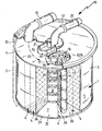
- the single FIGURE shows a partially sectioned illustration of a fuel filter 10 according to the invention of a motor vehicle for diesel fuel.
- the fuel filter 10 comprises a filter housing 2, which is closed by a detachable cover part 13.
- a replaceable filter element 1 is held, which can be removed in scheduled maintenance intervals after release of the cover part 13 and replaced with a new filter element 1.
- the filter element 1 comprises a filter body 3 with a filter material 5 arranged in folds 4.
- Filter material 5 is provided as filter material. However, other filter materials 5 may be useful.
- the course of the folds 4 is indicated by dashed lines 26.
- the filter housing 2 and the filter body 3 are constructed substantially cylindrical, wherein the folds 4 extend in the radial direction and extend parallel to the longitudinal axis of the cylindrical filter element 1 and the cylindrical filter housing 2.
- Radially outside the filter material 5 is a raw side 7 of the filter element 1.
- an approximately cylindrical cavity is provided which forms a clean side 8 of the filter element 1.
- the filter material 5 is flowed through radially from the outer raw side 7 to the inner clean side 8 out. This creates a differential pressure between the raw side 7 and the clean side 8, which acts on the filter material 5 radially inwardly.
- a support grid 24 is arranged radially inside.
- the filter body 3 each have an end plate 11, 22, at the edges of which circumferentially circumferential seals 12, 23 are arranged in the form of elastic sealing lips.
- the seal 12 situated in the region of the cover part 13 seals the end disk 11 both with respect to the filter housing 2 and with respect to the cover part 13.
- the seal 23 of the axially opposite end plate 22 is sealingly against the inner circumferential surface of the filter housing 2.
- a passage opening 16 is formed in the cover part 13 facing the end plate 11.
- the two end plates 11, 22 with their sealing lips 12, 23, the peripheral wall of the filter housing 2 and the filter body 3 define a closed annulus on the raw side 7 of the filter element 1, the only access is in the passage opening 16.
- a likewise closed inflow space 14 is formed as a result of the circumferential seal 12, into which an inflow line 15 opens.
- fuel is introduced through the inflow line 15.
- the fuel flows according to an arrow 25 through the inflow space 14 to the passage opening 16 and through it into the above-described annular space of the crude side 7. From there, the fuel flow radially from outside to inside through the filter material 5 into the radially inner, the clean side. 8 directed from where it flows through a central outflow line 20 of the cover part 13.
- a seal 21 running around the mouth of the outflow line 20 is arranged between the end plate 11 and the cover part 13.
- an electric heating element 6 is arranged for the fuel.
- the two adjacent folds 4 are spread apart in the circumferential direction to provide sufficient space for the heating element 6.
- the heating element 6 is offset radially inwardly relative to the circumferential contour of the filter body 3 and is fixedly connected to the filter element 1. At the scheduled maintenance intervals, a common replacement of the filter body 3 and the heating element 6 is provided.
- the heating element 6 extends axially parallel to the filter body 3 between the two end disks 11, 22.
- a contact opening 18 is formed which has an electrical plug connection with electrical connection contacts of the heating element 6 and a differential pressure sensor 9 described below allows.
- the heating element 6 is sealed with respect to the cover part 16 and the end plate 11 with a seal 19 surrounding the contact opening 18. As a result, the electrical connection contacts are kept away from the fuel flow.
- the passage opening 16 of the end disk 11 adjoins the associated front end of the heating element 6, wherein the hydrodynamic guide body 17 formed in the end disk 11 ensures a controlled flow of the heating element 6 with the fuel flow introduced through the passage opening 16.
- the fuel flow is guided approximately parallel to the axis along the heating element 6 and thereby heated. It then distributes itself in the above-described annular space of the raw side 7, before it is passed through the filter material 5 radially inwards to the clean side 8.
- a single heating element 6 between two folds 4 with an associated passage opening 16 is shown here. However, it may also be expedient to provide two or more heating elements 6 with a corresponding number of passage openings 16.
- the heating element 6 is still provided with an indicated differential pressure sensor 9, which is provided for detecting a differential pressure between the raw side 7 and the clean side 8 of the filter body 3.
- the resulting in the flow through the filter element 1 from the raw side 7 to the clean side 8 down differential pressure in the fuel flow is determined by the differential pressure sensor 9 and used in a control unit, not shown as a measure of the viscosity of the fuel.
- the delivery rate of an electric fuel pump (not shown) in the low-pressure circuit of the fuel supply and / or the heating power of the heating element 6 can be regulated or controlled to ensure a sufficient volume flow of the fuel through the fuel filter 10 even at low ambient temperatures.
Landscapes
- Engineering & Computer Science (AREA)
- Chemical & Material Sciences (AREA)
- Chemical Kinetics & Catalysis (AREA)
- Combustion & Propulsion (AREA)
- Mechanical Engineering (AREA)
- General Engineering & Computer Science (AREA)
- Filtration Of Liquid (AREA)
- Air-Conditioning For Vehicles (AREA)
Priority Applications (2)
| Application Number | Priority Date | Filing Date | Title |
|---|---|---|---|
| EP18155647.3A EP3346117A1 (de) | 2007-07-27 | 2008-07-22 | Filterelement und kraftstofffilter |
| PL12180355T PL2532874T3 (pl) | 2007-07-27 | 2008-07-22 | Element filtracyjny i filtr paliwa |
Applications Claiming Priority (2)
| Application Number | Priority Date | Filing Date | Title |
|---|---|---|---|
| DE202007010603U DE202007010603U1 (de) | 2007-07-27 | 2007-07-27 | Filterelement und Kraftstofffilter |
| EP08786299.1A EP2171250B1 (de) | 2007-07-27 | 2008-07-22 | Filterelement und kraftstofffilter |
Related Parent Applications (2)
| Application Number | Title | Priority Date | Filing Date |
|---|---|---|---|
| EP08786299.1 Division | 2008-07-22 | ||
| EP08786299.1A Division EP2171250B1 (de) | 2007-07-27 | 2008-07-22 | Filterelement und kraftstofffilter |
Related Child Applications (2)
| Application Number | Title | Priority Date | Filing Date |
|---|---|---|---|
| EP18155647.3A Division EP3346117A1 (de) | 2007-07-27 | 2008-07-22 | Filterelement und kraftstofffilter |
| EP18155647.3A Division-Into EP3346117A1 (de) | 2007-07-27 | 2008-07-22 | Filterelement und kraftstofffilter |
Publications (2)
| Publication Number | Publication Date |
|---|---|
| EP2532874A1 EP2532874A1 (de) | 2012-12-12 |
| EP2532874B1 true EP2532874B1 (de) | 2018-03-28 |
Family
ID=39884871
Family Applications (3)
| Application Number | Title | Priority Date | Filing Date |
|---|---|---|---|
| EP12180355.5A Active EP2532874B1 (de) | 2007-07-27 | 2008-07-22 | Filterelement und Kraftstofffilter |
| EP08786299.1A Active EP2171250B1 (de) | 2007-07-27 | 2008-07-22 | Filterelement und kraftstofffilter |
| EP18155647.3A Withdrawn EP3346117A1 (de) | 2007-07-27 | 2008-07-22 | Filterelement und kraftstofffilter |
Family Applications After (2)
| Application Number | Title | Priority Date | Filing Date |
|---|---|---|---|
| EP08786299.1A Active EP2171250B1 (de) | 2007-07-27 | 2008-07-22 | Filterelement und kraftstofffilter |
| EP18155647.3A Withdrawn EP3346117A1 (de) | 2007-07-27 | 2008-07-22 | Filterelement und kraftstofffilter |
Country Status (6)
| Country | Link |
|---|---|
| US (3) | US8535519B2 (pl) |
| EP (3) | EP2532874B1 (pl) |
| DE (1) | DE202007010603U1 (pl) |
| ES (1) | ES2667007T3 (pl) |
| PL (1) | PL2532874T3 (pl) |
| WO (1) | WO2009016063A1 (pl) |
Families Citing this family (10)
| Publication number | Priority date | Publication date | Assignee | Title |
|---|---|---|---|---|
| US10098737B2 (en) | 2009-10-29 | 2018-10-16 | Valtech Cardio, Ltd. | Tissue anchor for annuloplasty device |
| DE102013102233A1 (de) * | 2013-03-06 | 2014-09-11 | Emitec France S.A.S | Verfahren zur Entnahme eines flüssigen Additivs aus einem Tank |
| DE102014009323B4 (de) * | 2014-06-27 | 2016-11-24 | Mann + Hummel Gmbh | Filterelement eines Filters, Heizkäfig für ein Filterelement und Verfahren zur Herstellung eines Filterelements |
| KR101637295B1 (ko) * | 2014-12-02 | 2016-07-07 | 현대자동차 주식회사 | 디젤 연료 필터용 히터 제어 장치 및 그 구동 방법 |
| EP3184159A1 (en) | 2015-12-23 | 2017-06-28 | Wema System AS | Filtering system for fluid sensors especially for fuel tanks and sensor systems comprising same |
| US10233874B2 (en) * | 2016-03-01 | 2019-03-19 | CT Energy Holdings, LLC | Fuel heating apparatus and methods |
| WO2018193165A1 (en) | 2017-04-21 | 2018-10-25 | Ahlstrom-Munksjö Oyj | Filter units provided with high-efficiency and high capacity glass-free fuel filtration media |
| DE102018208901A1 (de) * | 2018-06-06 | 2019-12-12 | Robert Bosch Gmbh | Wassereinspritzvorrichtung für eine Brennkraftmaschine |
| CN113813676A (zh) * | 2021-10-31 | 2021-12-21 | 康硕(江西)智能制造有限公司 | 一种便携3d打印用陶瓷浆料过滤器 |
| US20250314184A1 (en) * | 2023-11-21 | 2025-10-09 | Matthew Risley | Oil catch can |
Family Cites Families (8)
| Publication number | Priority date | Publication date | Assignee | Title |
|---|---|---|---|---|
| US3235084A (en) * | 1962-01-30 | 1966-02-15 | Stewart Warner Corp | Fuel filter with heating unit |
| DE2721607A1 (de) * | 1977-05-13 | 1978-11-16 | Bosch Gmbh Robert | Fluessigkeitsfilter |
| US4600825A (en) | 1981-06-03 | 1986-07-15 | Walter Blazejovsky | Electrically heated diesel engine fuel conveying system |
| DE3624276A1 (de) | 1986-07-18 | 1988-01-28 | Opel Adam Ag | Elektrisch heizbare filtereinrichtung fuer eine fluessigkeit und verfahren zu ihrer herstellung |
| DE19945772A1 (de) | 1999-09-24 | 2001-03-29 | Deere & Co | Betriebstoffilter, Filterelement und Fahrzeug |
| DE19955206A1 (de) * | 1999-11-17 | 2001-07-05 | Mann & Hummel Filter | Kraftstofffilter |
| DE10221566A1 (de) | 2002-05-15 | 2003-11-27 | Bosch Gmbh Robert | Filter zum Einsatz in einem strömenden, viskosen Medium |
| ITRE20050139A1 (it) * | 2005-12-13 | 2007-06-14 | Ufi Filters Spa | Filtro per carburante diesel con riscaldatore |
-
2007
- 2007-07-27 DE DE202007010603U patent/DE202007010603U1/de not_active Expired - Lifetime
-
2008
- 2008-07-22 EP EP12180355.5A patent/EP2532874B1/de active Active
- 2008-07-22 US US12/671,027 patent/US8535519B2/en active Active
- 2008-07-22 WO PCT/EP2008/059563 patent/WO2009016063A1/de not_active Ceased
- 2008-07-22 PL PL12180355T patent/PL2532874T3/pl unknown
- 2008-07-22 EP EP08786299.1A patent/EP2171250B1/de active Active
- 2008-07-22 EP EP18155647.3A patent/EP3346117A1/de not_active Withdrawn
- 2008-07-22 ES ES12180355.5T patent/ES2667007T3/es active Active
-
2013
- 2013-05-16 US US13/895,860 patent/US8696894B2/en not_active Expired - Fee Related
-
2014
- 2014-03-11 US US14/204,755 patent/US9592461B2/en active Active
Non-Patent Citations (1)
| Title |
|---|
| None * |
Also Published As
| Publication number | Publication date |
|---|---|
| ES2667007T3 (es) | 2018-05-09 |
| EP3346117A1 (de) | 2018-07-11 |
| US9592461B2 (en) | 2017-03-14 |
| US8696894B2 (en) | 2014-04-15 |
| EP2171250A1 (de) | 2010-04-07 |
| US8535519B2 (en) | 2013-09-17 |
| US20130248427A1 (en) | 2013-09-26 |
| DE202007010603U1 (de) | 2008-12-18 |
| US20100276346A1 (en) | 2010-11-04 |
| US20140216997A1 (en) | 2014-08-07 |
| EP2171250B1 (de) | 2013-04-24 |
| PL2532874T3 (pl) | 2018-09-28 |
| WO2009016063A1 (de) | 2009-02-05 |
| EP2532874A1 (de) | 2012-12-12 |
Similar Documents
| Publication | Publication Date | Title |
|---|---|---|
| EP2532874B1 (de) | Filterelement und Kraftstofffilter | |
| DE102013009198B4 (de) | Filter für Fluid und Verfahren zur Montage eines Filterelements in einem Filtergehäuse | |
| EP1593419B1 (de) | Filterelement und Flüssigkeitsfilter für einfriergefährdete Fluide sowie Verfahren zur Herstellung des Filterelementes | |
| EP2514958B1 (de) | Kraftstofffilter für eine Brennkraftmaschine | |
| EP2600962A1 (de) | Fluidfilter | |
| EP2104545B1 (de) | Flüssigkeitsfilter | |
| EP3096859A1 (de) | Filterelement | |
| DE102013223352A1 (de) | Flüssigkeitsfilter | |
| EP2808071B1 (de) | Filtereinrichtung, insbesondere für ein Kraftfahrzeug | |
| EP1130224A1 (de) | Flüssigkeitsfilter mit einem Kühler | |
| DE102014010389A1 (de) | Filter für Flüssigkeit mit wenigstens einer Heizeinrichtung und Verfahren zur Herstellung eines Filters | |
| EP2532848B1 (de) | Filter- und Kühlvorrichtung | |
| EP3037150A1 (de) | Filtereinrichtung | |
| DE3938686C2 (de) | Vorrichtung zum Vorbereiten von Dieselkraftstoff zur Verbrennung | |
| EP1087128A2 (de) | Betriebsstoffilter, Filterelement und Fahrzeug | |
| DE102016003521A1 (de) | Filterelement eines Filters, Filter und Fluidsystem mit wenigstens einem Filterelement | |
| EP2636437A1 (de) | Filtereinrichtung | |
| DE102015008694A1 (de) | Hohlfilterelement eines Flüssigkeitsfilters, Flüssigkeitsfilter, Filtersystem und Adapterelement eines Hohlfilterelements | |
| EP3510835B1 (de) | Ringförmiges heizelement | |
| DE102014005348B4 (de) | Filterelement eines Filters und Filter | |
| DE10200274A1 (de) | Kraftstofffilterelement | |
| DE102013101792B4 (de) | Wärmepumpe | |
| EP1128058A2 (de) | Verfahren zum Betreiben einer Filtereinrichtung für Dieselkraftstoff eines Kraftfahrzeug-Verbrennungsmotors und Ausgestaltungen dieser Einrichtung | |
| DE102005050361A1 (de) | Schnappflansch für eine Spritzgiessdüse | |
| DE8913769U1 (de) | Vorrichtung zum Vorbereiten von Dieselkraftstoff zur Verbrennung |
Legal Events
| Date | Code | Title | Description |
|---|---|---|---|
| PUAI | Public reference made under article 153(3) epc to a published international application that has entered the european phase |
Free format text: ORIGINAL CODE: 0009012 |
|
| AC | Divisional application: reference to earlier application |
Ref document number: 2171250 Country of ref document: EP Kind code of ref document: P |
|
| AK | Designated contracting states |
Kind code of ref document: A1 Designated state(s): AT BE BG CH CY CZ DE DK EE ES FI FR GB GR HR HU IE IS IT LI LT LU LV MC MT NL NO PL PT RO SE SI SK TR |
|
| 17P | Request for examination filed |
Effective date: 20130612 |
|
| RBV | Designated contracting states (corrected) |
Designated state(s): AT BE BG CH CY CZ DE DK EE ES FI FR GB GR HR HU IE IS IT LI LT LU LV MC MT NL NO PL PT RO SE SI SK TR |
|
| RIC1 | Information provided on ipc code assigned before grant |
Ipc: F02M 37/22 20060101ALI20130731BHEP Ipc: B01D 35/18 20060101ALI20130731BHEP Ipc: F02M 31/125 20060101AFI20130731BHEP Ipc: B01D 27/06 20060101ALI20130731BHEP Ipc: B01D 29/60 20060101ALI20130731BHEP |
|
| GRAP | Despatch of communication of intention to grant a patent |
Free format text: ORIGINAL CODE: EPIDOSNIGR1 |
|
| INTG | Intention to grant announced |
Effective date: 20131212 |
|
| 17Q | First examination report despatched |
Effective date: 20140708 |
|
| APBK | Appeal reference recorded |
Free format text: ORIGINAL CODE: EPIDOSNREFNE |
|
| APBN | Date of receipt of notice of appeal recorded |
Free format text: ORIGINAL CODE: EPIDOSNNOA2E |
|
| APBR | Date of receipt of statement of grounds of appeal recorded |
Free format text: ORIGINAL CODE: EPIDOSNNOA3E |
|
| APAF | Appeal reference modified |
Free format text: ORIGINAL CODE: EPIDOSCREFNE |
|
| INTC | Intention to grant announced (deleted) | ||
| APBT | Appeal procedure closed |
Free format text: ORIGINAL CODE: EPIDOSNNOA9E |
|
| GRAP | Despatch of communication of intention to grant a patent |
Free format text: ORIGINAL CODE: EPIDOSNIGR1 |
|
| INTG | Intention to grant announced |
Effective date: 20171009 |
|
| GRAS | Grant fee paid |
Free format text: ORIGINAL CODE: EPIDOSNIGR3 |
|
| GRAA | (expected) grant |
Free format text: ORIGINAL CODE: 0009210 |
|
| RIN1 | Information on inventor provided before grant (corrected) |
Inventor name: JOKSCHAS, GUENTER Inventor name: ROESGEN, ANDRE |
|
| RAP1 | Party data changed (applicant data changed or rights of an application transferred) |
Owner name: MANN + HUMMEL GMBH |
|
| AC | Divisional application: reference to earlier application |
Ref document number: 2171250 Country of ref document: EP Kind code of ref document: P |
|
| AK | Designated contracting states |
Kind code of ref document: B1 Designated state(s): AT BE BG CH CY CZ DE DK EE ES FI FR GB GR HR HU IE IS IT LI LT LU LV MC MT NL NO PL PT RO SE SI SK TR |
|
| REG | Reference to a national code |
Ref country code: GB Ref legal event code: FG4D Free format text: NOT ENGLISH |
|
| REG | Reference to a national code |
Ref country code: CH Ref legal event code: EP |
|
| REG | Reference to a national code |
Ref country code: AT Ref legal event code: REF Ref document number: 983670 Country of ref document: AT Kind code of ref document: T Effective date: 20180415 |
|
| REG | Reference to a national code |
Ref country code: IE Ref legal event code: FG4D Free format text: LANGUAGE OF EP DOCUMENT: GERMAN |
|
| REG | Reference to a national code |
Ref country code: DE Ref legal event code: R096 Ref document number: 502008015993 Country of ref document: DE |
|
| REG | Reference to a national code |
Ref country code: ES Ref legal event code: FG2A Ref document number: 2667007 Country of ref document: ES Kind code of ref document: T3 Effective date: 20180509 |
|
| REG | Reference to a national code |
Ref country code: DE Ref legal event code: R081 Ref document number: 502008015993 Country of ref document: DE Owner name: MANN+HUMMEL GMBH, DE Free format text: FORMER OWNER: MANN+HUMMEL GMBH, 71636 LUDWIGSBURG, DE |
|
| REG | Reference to a national code |
Ref country code: FR Ref legal event code: PLFP Year of fee payment: 11 |
|
| PG25 | Lapsed in a contracting state [announced via postgrant information from national office to epo] |
Ref country code: LT Free format text: LAPSE BECAUSE OF FAILURE TO SUBMIT A TRANSLATION OF THE DESCRIPTION OR TO PAY THE FEE WITHIN THE PRESCRIBED TIME-LIMIT Effective date: 20180328 Ref country code: HR Free format text: LAPSE BECAUSE OF FAILURE TO SUBMIT A TRANSLATION OF THE DESCRIPTION OR TO PAY THE FEE WITHIN THE PRESCRIBED TIME-LIMIT Effective date: 20180328 Ref country code: NO Free format text: LAPSE BECAUSE OF FAILURE TO SUBMIT A TRANSLATION OF THE DESCRIPTION OR TO PAY THE FEE WITHIN THE PRESCRIBED TIME-LIMIT Effective date: 20180628 Ref country code: FI Free format text: LAPSE BECAUSE OF FAILURE TO SUBMIT A TRANSLATION OF THE DESCRIPTION OR TO PAY THE FEE WITHIN THE PRESCRIBED TIME-LIMIT Effective date: 20180328 |
|
| REG | Reference to a national code |
Ref country code: NL Ref legal event code: MP Effective date: 20180328 |
|
| REG | Reference to a national code |
Ref country code: LT Ref legal event code: MG4D |
|
| PG25 | Lapsed in a contracting state [announced via postgrant information from national office to epo] |
Ref country code: SE Free format text: LAPSE BECAUSE OF FAILURE TO SUBMIT A TRANSLATION OF THE DESCRIPTION OR TO PAY THE FEE WITHIN THE PRESCRIBED TIME-LIMIT Effective date: 20180328 Ref country code: LV Free format text: LAPSE BECAUSE OF FAILURE TO SUBMIT A TRANSLATION OF THE DESCRIPTION OR TO PAY THE FEE WITHIN THE PRESCRIBED TIME-LIMIT Effective date: 20180328 Ref country code: GR Free format text: LAPSE BECAUSE OF FAILURE TO SUBMIT A TRANSLATION OF THE DESCRIPTION OR TO PAY THE FEE WITHIN THE PRESCRIBED TIME-LIMIT Effective date: 20180629 |
|
| PG25 | Lapsed in a contracting state [announced via postgrant information from national office to epo] |
Ref country code: MT Free format text: LAPSE BECAUSE OF FAILURE TO SUBMIT A TRANSLATION OF THE DESCRIPTION OR TO PAY THE FEE WITHIN THE PRESCRIBED TIME-LIMIT Effective date: 20180328 |
|
| PG25 | Lapsed in a contracting state [announced via postgrant information from national office to epo] |
Ref country code: NL Free format text: LAPSE BECAUSE OF FAILURE TO SUBMIT A TRANSLATION OF THE DESCRIPTION OR TO PAY THE FEE WITHIN THE PRESCRIBED TIME-LIMIT Effective date: 20180328 Ref country code: EE Free format text: LAPSE BECAUSE OF FAILURE TO SUBMIT A TRANSLATION OF THE DESCRIPTION OR TO PAY THE FEE WITHIN THE PRESCRIBED TIME-LIMIT Effective date: 20180328 Ref country code: RO Free format text: LAPSE BECAUSE OF FAILURE TO SUBMIT A TRANSLATION OF THE DESCRIPTION OR TO PAY THE FEE WITHIN THE PRESCRIBED TIME-LIMIT Effective date: 20180328 |
|
| PG25 | Lapsed in a contracting state [announced via postgrant information from national office to epo] |
Ref country code: SK Free format text: LAPSE BECAUSE OF FAILURE TO SUBMIT A TRANSLATION OF THE DESCRIPTION OR TO PAY THE FEE WITHIN THE PRESCRIBED TIME-LIMIT Effective date: 20180328 |
|
| PG25 | Lapsed in a contracting state [announced via postgrant information from national office to epo] |
Ref country code: PT Free format text: LAPSE BECAUSE OF FAILURE TO SUBMIT A TRANSLATION OF THE DESCRIPTION OR TO PAY THE FEE WITHIN THE PRESCRIBED TIME-LIMIT Effective date: 20180730 |
|
| REG | Reference to a national code |
Ref country code: DE Ref legal event code: R097 Ref document number: 502008015993 Country of ref document: DE |
|
| PG25 | Lapsed in a contracting state [announced via postgrant information from national office to epo] |
Ref country code: DK Free format text: LAPSE BECAUSE OF FAILURE TO SUBMIT A TRANSLATION OF THE DESCRIPTION OR TO PAY THE FEE WITHIN THE PRESCRIBED TIME-LIMIT Effective date: 20180328 |
|
| PLBE | No opposition filed within time limit |
Free format text: ORIGINAL CODE: 0009261 |
|
| STAA | Information on the status of an ep patent application or granted ep patent |
Free format text: STATUS: NO OPPOSITION FILED WITHIN TIME LIMIT |
|
| REG | Reference to a national code |
Ref country code: CH Ref legal event code: PL |
|
| 26N | No opposition filed |
Effective date: 20190103 |
|
| PG25 | Lapsed in a contracting state [announced via postgrant information from national office to epo] |
Ref country code: MC Free format text: LAPSE BECAUSE OF FAILURE TO SUBMIT A TRANSLATION OF THE DESCRIPTION OR TO PAY THE FEE WITHIN THE PRESCRIBED TIME-LIMIT Effective date: 20180328 Ref country code: LU Free format text: LAPSE BECAUSE OF NON-PAYMENT OF DUE FEES Effective date: 20180722 |
|
| REG | Reference to a national code |
Ref country code: BE Ref legal event code: MM Effective date: 20180731 |
|
| REG | Reference to a national code |
Ref country code: IE Ref legal event code: MM4A |
|
| PG25 | Lapsed in a contracting state [announced via postgrant information from national office to epo] |
Ref country code: CH Free format text: LAPSE BECAUSE OF NON-PAYMENT OF DUE FEES Effective date: 20180731 Ref country code: IE Free format text: LAPSE BECAUSE OF NON-PAYMENT OF DUE FEES Effective date: 20180722 Ref country code: LI Free format text: LAPSE BECAUSE OF NON-PAYMENT OF DUE FEES Effective date: 20180731 |
|
| PG25 | Lapsed in a contracting state [announced via postgrant information from national office to epo] |
Ref country code: SI Free format text: LAPSE BECAUSE OF FAILURE TO SUBMIT A TRANSLATION OF THE DESCRIPTION OR TO PAY THE FEE WITHIN THE PRESCRIBED TIME-LIMIT Effective date: 20180328 Ref country code: BE Free format text: LAPSE BECAUSE OF NON-PAYMENT OF DUE FEES Effective date: 20180731 |
|
| REG | Reference to a national code |
Ref country code: AT Ref legal event code: MM01 Ref document number: 983670 Country of ref document: AT Kind code of ref document: T Effective date: 20180722 |
|
| PG25 | Lapsed in a contracting state [announced via postgrant information from national office to epo] |
Ref country code: AT Free format text: LAPSE BECAUSE OF NON-PAYMENT OF DUE FEES Effective date: 20180722 |
|
| PG25 | Lapsed in a contracting state [announced via postgrant information from national office to epo] |
Ref country code: TR Free format text: LAPSE BECAUSE OF FAILURE TO SUBMIT A TRANSLATION OF THE DESCRIPTION OR TO PAY THE FEE WITHIN THE PRESCRIBED TIME-LIMIT Effective date: 20180328 |
|
| PG25 | Lapsed in a contracting state [announced via postgrant information from national office to epo] |
Ref country code: HU Free format text: LAPSE BECAUSE OF FAILURE TO SUBMIT A TRANSLATION OF THE DESCRIPTION OR TO PAY THE FEE WITHIN THE PRESCRIBED TIME-LIMIT; INVALID AB INITIO Effective date: 20080722 |
|
| PG25 | Lapsed in a contracting state [announced via postgrant information from national office to epo] |
Ref country code: CY Free format text: LAPSE BECAUSE OF FAILURE TO SUBMIT A TRANSLATION OF THE DESCRIPTION OR TO PAY THE FEE WITHIN THE PRESCRIBED TIME-LIMIT Effective date: 20180328 |
|
| PG25 | Lapsed in a contracting state [announced via postgrant information from national office to epo] |
Ref country code: IS Free format text: LAPSE BECAUSE OF FAILURE TO SUBMIT A TRANSLATION OF THE DESCRIPTION OR TO PAY THE FEE WITHIN THE PRESCRIBED TIME-LIMIT Effective date: 20180728 |
|
| P01 | Opt-out of the competence of the unified patent court (upc) registered |
Effective date: 20230601 |
|
| PGFP | Annual fee paid to national office [announced via postgrant information from national office to epo] |
Ref country code: ES Payment date: 20250826 Year of fee payment: 18 |
|
| PGFP | Annual fee paid to national office [announced via postgrant information from national office to epo] |
Ref country code: DE Payment date: 20250722 Year of fee payment: 18 |
|
| PGFP | Annual fee paid to national office [announced via postgrant information from national office to epo] |
Ref country code: PL Payment date: 20250710 Year of fee payment: 18 Ref country code: IT Payment date: 20250724 Year of fee payment: 18 |
|
| PGFP | Annual fee paid to national office [announced via postgrant information from national office to epo] |
Ref country code: BG Payment date: 20250722 Year of fee payment: 18 Ref country code: GB Payment date: 20250722 Year of fee payment: 18 |
|
| PGFP | Annual fee paid to national office [announced via postgrant information from national office to epo] |
Ref country code: FR Payment date: 20250725 Year of fee payment: 18 |
|
| PGFP | Annual fee paid to national office [announced via postgrant information from national office to epo] |
Ref country code: CZ Payment date: 20250715 Year of fee payment: 18 |