EP2532844A1 - Power generation apparatus - Google Patents
Power generation apparatus Download PDFInfo
- Publication number
- EP2532844A1 EP2532844A1 EP12169716A EP12169716A EP2532844A1 EP 2532844 A1 EP2532844 A1 EP 2532844A1 EP 12169716 A EP12169716 A EP 12169716A EP 12169716 A EP12169716 A EP 12169716A EP 2532844 A1 EP2532844 A1 EP 2532844A1
- Authority
- EP
- European Patent Office
- Prior art keywords
- pump
- valve
- working medium
- channel
- liquid
- Prior art date
- Legal status (The legal status is an assumption and is not a legal conclusion. Google has not performed a legal analysis and makes no representation as to the accuracy of the status listed.)
- Granted
Links
- 238000010248 power generation Methods 0.000 title claims abstract description 16
- 239000007788 liquid Substances 0.000 claims description 66
- 238000011144 upstream manufacturing Methods 0.000 claims description 22
- 239000002826 coolant Substances 0.000 claims description 17
- 238000001816 cooling Methods 0.000 claims description 3
- 238000010438 heat treatment Methods 0.000 claims description 3
- 239000002918 waste heat Substances 0.000 description 15
- 239000012530 fluid Substances 0.000 description 11
- 238000000034 method Methods 0.000 description 7
- 230000007246 mechanism Effects 0.000 description 5
- 239000000470 constituent Substances 0.000 description 4
- 230000008569 process Effects 0.000 description 4
- 229920006395 saturated elastomer Polymers 0.000 description 4
- 238000010586 diagram Methods 0.000 description 3
- 230000005611 electricity Effects 0.000 description 3
- XLYOFNOQVPJJNP-UHFFFAOYSA-N water Substances O XLYOFNOQVPJJNP-UHFFFAOYSA-N 0.000 description 3
- 238000009835 boiling Methods 0.000 description 2
- 230000000694 effects Effects 0.000 description 2
- 239000002028 Biomass Substances 0.000 description 1
- 101000911772 Homo sapiens Hsc70-interacting protein Proteins 0.000 description 1
- 101000710013 Homo sapiens Reversion-inducing cysteine-rich protein with Kazal motifs Proteins 0.000 description 1
- 238000001514 detection method Methods 0.000 description 1
- 238000004134 energy conservation Methods 0.000 description 1
- 238000005516 engineering process Methods 0.000 description 1
- 230000003628 erosive effect Effects 0.000 description 1
- 239000002803 fossil fuel Substances 0.000 description 1
- 238000012423 maintenance Methods 0.000 description 1
- 238000012986 modification Methods 0.000 description 1
- 230000004048 modification Effects 0.000 description 1
- MSSNHSVIGIHOJA-UHFFFAOYSA-N pentafluoropropane Chemical compound FC(F)CC(F)(F)F MSSNHSVIGIHOJA-UHFFFAOYSA-N 0.000 description 1
- 239000000565 sealant Substances 0.000 description 1
- 238000005382 thermal cycling Methods 0.000 description 1
- 238000004804 winding Methods 0.000 description 1
Images


Classifications
-
- F—MECHANICAL ENGINEERING; LIGHTING; HEATING; WEAPONS; BLASTING
- F01—MACHINES OR ENGINES IN GENERAL; ENGINE PLANTS IN GENERAL; STEAM ENGINES
- F01K—STEAM ENGINE PLANTS; STEAM ACCUMULATORS; ENGINE PLANTS NOT OTHERWISE PROVIDED FOR; ENGINES USING SPECIAL WORKING FLUIDS OR CYCLES
- F01K23/00—Plants characterised by more than one engine delivering power external to the plant, the engines being driven by different fluids
- F01K23/02—Plants characterised by more than one engine delivering power external to the plant, the engines being driven by different fluids the engine cycles being thermally coupled
- F01K23/06—Plants characterised by more than one engine delivering power external to the plant, the engines being driven by different fluids the engine cycles being thermally coupled combustion heat from one cycle heating the fluid in another cycle
- F01K23/10—Plants characterised by more than one engine delivering power external to the plant, the engines being driven by different fluids the engine cycles being thermally coupled combustion heat from one cycle heating the fluid in another cycle with exhaust fluid of one cycle heating the fluid in another cycle
-
- F—MECHANICAL ENGINEERING; LIGHTING; HEATING; WEAPONS; BLASTING
- F01—MACHINES OR ENGINES IN GENERAL; ENGINE PLANTS IN GENERAL; STEAM ENGINES
- F01K—STEAM ENGINE PLANTS; STEAM ACCUMULATORS; ENGINE PLANTS NOT OTHERWISE PROVIDED FOR; ENGINES USING SPECIAL WORKING FLUIDS OR CYCLES
- F01K13/00—General layout or general methods of operation of complete plants
- F01K13/02—Controlling, e.g. stopping or starting
-
- F—MECHANICAL ENGINEERING; LIGHTING; HEATING; WEAPONS; BLASTING
- F01—MACHINES OR ENGINES IN GENERAL; ENGINE PLANTS IN GENERAL; STEAM ENGINES
- F01D—NON-POSITIVE DISPLACEMENT MACHINES OR ENGINES, e.g. STEAM TURBINES
- F01D15/00—Adaptations of machines or engines for special use; Combinations of engines with devices driven thereby
- F01D15/10—Adaptations for driving, or combinations with, electric generators
-
- F—MECHANICAL ENGINEERING; LIGHTING; HEATING; WEAPONS; BLASTING
- F01—MACHINES OR ENGINES IN GENERAL; ENGINE PLANTS IN GENERAL; STEAM ENGINES
- F01K—STEAM ENGINE PLANTS; STEAM ACCUMULATORS; ENGINE PLANTS NOT OTHERWISE PROVIDED FOR; ENGINES USING SPECIAL WORKING FLUIDS OR CYCLES
- F01K25/00—Plants or engines characterised by use of special working fluids, not otherwise provided for; Plants operating in closed cycles and not otherwise provided for
- F01K25/02—Plants or engines characterised by use of special working fluids, not otherwise provided for; Plants operating in closed cycles and not otherwise provided for the fluid remaining in the liquid phase
-
- F—MECHANICAL ENGINEERING; LIGHTING; HEATING; WEAPONS; BLASTING
- F01—MACHINES OR ENGINES IN GENERAL; ENGINE PLANTS IN GENERAL; STEAM ENGINES
- F01K—STEAM ENGINE PLANTS; STEAM ACCUMULATORS; ENGINE PLANTS NOT OTHERWISE PROVIDED FOR; ENGINES USING SPECIAL WORKING FLUIDS OR CYCLES
- F01K3/00—Plants characterised by the use of steam or heat accumulators, or intermediate steam heaters, therein
- F01K3/18—Plants characterised by the use of steam or heat accumulators, or intermediate steam heaters, therein having heaters
- F01K3/20—Plants characterised by the use of steam or heat accumulators, or intermediate steam heaters, therein having heaters with heating by combustion gases of main boiler
- F01K3/22—Controlling, e.g. starting, stopping
Definitions
- the present invention relates to power generation apparatuses used in electric power generators and the like.
- the waste heat electric power generator disclosed in, for example, Japanese Patent No. 4557793 is known as such an electric power generator.
- This waste heat electric power generator includes a closed-loop circulating channel in which a working fluid evaporator, a turbine for causing the working fluid vapor to expand, a condenser for condensing the working fluid vapor, and pumps for circulating the working fluid are connected in series. Thermal cycling is carried out in the circulating channel when the working fluid is being cycled, while the stated turbine generates power and drives an electric generator using that power.
- binary generation systems which use the Rankine cycle to drive turbines, expanders, or the like using a low boiling point working fluid, are well-known.
- the stated waste heat electric power generator includes a steam generator that collects waste heat and generates high-pressure working medium vapor from the working medium, a turbine that expands the high-pressure working medium vapor, a condenser that condenses low-pressure vapor from the turbine, and a working medium circulating pump that circulates the working medium. These elements are connected by a working medium circulation channel, and a gas-liquid separator is disposed between the steam generator and the turbine. Working medium vapor that has been separated from the working medium liquid by the gas-liquid separator is introduced into the turbine.
- Cavitation is a phenomenon in which, in a fluid mechanism, the pressure of a medium (liquid) that flows within the fluid mechanism reaches the maximum vapor tension locally, causing the medium to boil and producing small bubbles. When these bubbles are burst, the impact pressure thereof causes what is known as erosion in the constituent components of the fluid mechanism.
- the fluid mechanism is a turbo fluid mechanism
- the impeller which is the primary component thereof, will be damaged.
- this waste heat electric power generator is provided with a circulation amount control means that controls the amount of the working medium that is to be circulated from the condenser to the steam generator, and a liquid surface detector that detects the surface of the liquid separated in the gas-liquid separator.
- the separated liquid (working medium) separated by the gas-liquid separator is introduced to the condenser via a flow amount control means, and the circulation amount control means controls the circulation amount of the working medium so that the separated liquid surface within the gas-liquid separator detected by the liquid surface detector reaches a predetermined level.
- this waste heat electric power generator is provided with a heat collector.
- the heat collector is provided along the channel the leads the separated liquid from the gas-liquid separator to the condenser, and exchanges heat between the separated liquid and the working medium fed from the condenser to the steam generator.
- a power generation apparatus includes: a steam generation means that evaporates a liquid working medium by heating the working medium using a thermal medium; an expander that expands the gaseous working medium and produces power as a result; a condensing means that condenses the gaseous working medium by cooling the working medium using a coolant medium; a pump that circulates the working medium; a closed-loop circulating channel in which the steam generation means, the expander, the condensing means, and the pump are connected in series; a first on/off valve provided in the circulating channel between the steam generation means and the expander; a bypass channel connected between an area in the circulating channel between the steam generation means and the first on/off valve and an area between the expander and the condensing means; a second on/off valve provided in the bypass channel; a third on/off valve provided in the circulating channel between the pump and the steam generation means; and a control means that carries out control for starting and stopping the pump and
- the control means when stopping the pump, the control means outputs a control signal that stops the pump, a control signal that closes the first on/off valve, a control signal that opens the second on/off valve, and a control signal that closes the third on/off valve, and then, in the case where a predetermined condition has been met, outputs a control signal that closes the second on/off valve.
- the working medium which has been heated by the thermal medium in the steam generation means and is thus in a gaseous state flows into the condensing means through the bypass channel, is cooled by the coolant medium in the condensing means, and returns to a liquid state; therefore, by opening the second on/off valve during a period up until a predetermined amount of the liquid-state working medium is accumulated, a state in which the channel upstream from the pump is filled with the liquid-state working medium can be ensured when starting the pump, which makes it possible to reduce the risk of cavitation.
- the bypass channel having the on/off valve is simply connected to the circulating channel, which makes it possible to avoid complicating the structure.
- the predetermined condition prefferably be that an amount of time has been set in advance by the control means as an amount of time from when the second on/off valve is opened to when a predetermined amount of the liquid working medium has accumulated in the circulating channel upstream from the pump.
- the power generation apparatus prefferably includes a liquid surface meter provided in the condensing means, which is capable of detecting the height of a liquid surface within the condensing means, and for the predetermined condition to be that the value of the liquid surface meter has reached a predetermined value.
- the power generation apparatus prefferably includes a liquid tank provided in the circulating channel between the condensing means and the pump and a liquid surface meter provided in the liquid tank, the liquid surface meter being capable of detecting the height of a liquid surface within the liquid tank, and for the predetermined condition to be that the value of the liquid surface meter has reached a predetermined value.
- the channel upstream from the pump is filled with liquid-state working medium based on the value detected by the liquid surface meter (level gauge), which makes it easy to ensure that a state where the channel upstream from the pump is filled with liquid-state working medium and thus makes it possible to further reduce the risk of cavitation in the pump; furthermore, because the liquid tank is provided, a high amount of liquid-state working medium can be ensured in the channel upstream from the pump.
- level gauge level gauge
- the occurrence of cavitation in a pump that circulates a working medium can be suppressed without complicating the structure.
- Fig. 1 illustrates the configuration of an electric power generator 100 according to a first embodiment of a power generation apparatus according to the present invention.
- the electric power generator 100 includes a closed-loop circulating channel 6 in which are provided an expander 1, an oil separator 2, a condenser (condensing means) 3, a working medium pump 4, and an evaporator (steam generator, steam generation means) 5.
- a Freon-based medium (for example, R245fa) is injected into the circulating channel 6 as a working medium.
- a medium with a lower boiling point than that of water is used, and the electric power generator 100 according to the present embodiment is configured as a binary electric power generator.
- the expander 1 is disposed downstream from the evaporator 5 in the circulating channel 6, and obtains kinetic energy from the working medium by expanding the working medium evaporated by the evaporator 5 (vapor).
- the expander 1 is configured of, for example, a screw expander.
- This screw expander has a pair of male and female screw rotors (not shown) housed within a rotor chamber (not shown) formed in an expander casing, and rotates the screw rotors using the expansion force of the working medium supplied from an intake port 1s via the circulating channel 6.
- the working medium that has been expanded in the rotor chamber and whose pressure has dropped is then exhausted to the circulating channel 6 from an exhaust port 1d.
- the oil separator 2 is provided between the expander 1 and the condenser 3 in the circulating channel 6, and an oil flow channel 18 having an oil pump 17 is provided between the oil separator 2 and the expander 1.
- the oil separator 2 separates oil that is exhausted from the expander 1 along with the working medium and holds the separated oil in its interior.
- the oil held in the oil separator 2 is supplied to the interior of the expander 1 via the oil flow channel 18.
- the oil supplied to the interior of the expander 1 functions as a sealant between the screw rotors and between the screw rotors and the rotor chamber, and works so as to prevent a drop in the efficiency of the expansion of the working medium.
- An electric generator 9 is connected to the expander 1, and the electric generator 9 is driven by the power generated by the expander 1 being transmitted to the electric generator 9.
- the electric generator 9 is configured so that a stator (not shown) and a rotor (not shown) are housed within the internal space of an electric generator casing (not shown).
- the rotor has a shaft that is integrated with the shaft of the screw rotors in the expander 1, and by rotating along with the rotation of the screw rotors, causes a winding around the stator to generate electricity.
- the expander 1 and the electric generator 9 configure an electricity generation means.
- the condenser 3 is disposed downstream from the expander 1, and more specifically, is disposed downstream from the oil separator 2, in the circulating channel 6; the working medium that has been exhausted into the circulating channel 6 from the exhaust port 1d of the expander 1, from which the oil has been separated and is thus in a gaseous state, is introduced into the condenser 3.
- the working medium is condensed through heat exchange with a coolant medium (for example, coolant water) that flows through a coolant medium channel 8 in a system separate from the circulating channel 6, thus becoming a liquid-state working medium.
- the condenser 3 includes a channel through which the working medium flows and a channel through which the coolant medium flows, and condenses the working medium by instigating heat exchange between the gaseous working medium and the coolant medium.
- the working medium that has become a liquid is pressurized by the pump 4 to a predetermined pressure, and is then sent to the evaporator 5.
- the working medium is heated through heat exchange with a thermal medium (for example, a low-pressure vapor) that flows through a thermal medium channel 7 in a system separate from the circulating channel 6, thus becoming a saturated vapor (or a superheated vapor).
- a thermal medium for example, a low-pressure vapor
- the evaporator 5 includes a channel through which the working medium flows and a channel through which the thermal medium, which is supplied from an external heat source, flows, and vaporizes the working medium into a saturated vapor (or a superheated vapor) by instigating heat exchange between the working medium in a liquid state and the thermal medium.
- the working medium that has been turned into a saturated vapor (or a superheated vapor) by the evaporator 5 is once again supplied to the expander 1.
- thermal medium heat source supplied to the evaporator 5 via the thermal medium channel 7.
- coolant water created by cooling towers can be considered as the coolant medium supplied to the condenser 3 via the coolant medium channel 8.
- the pump 4 is provided for circulating the working medium within the circulating channel 6, and is disposed downstream from the condenser 3 in the circulating channel 6.
- the pump 4 is provided in the circulating channel 6 so as to connect the condenser 3 and the evaporator 5, and takes in the working medium (liquid) from the condenser 3 side and ejects the working medium to the evaporator 5 side.
- a centrifugal pump that uses an impeller as its rotor, a gear pump in which the rotor is configured of a pair of gears, or the like can be used favorably as the pump 4.
- a first on/off valve 11 (V1) is provided between the evaporator 5 and the expander 1 in the circulating channel 6. Meanwhile, a bypass channel 10 is provided in the circulating channel 6 so as to connect the area downstream from the evaporator 5 and the area upstream from the condenser 3; more specifically, the bypass channel 10 is connected from between the evaporator 5 and the first on/off valve 11 to between the expander 1 and the condenser 3.
- a second on/off valve 12 (V2) is provided in the bypass channel 10.
- a third on/off valve 13 (V3) is provided in the circulating channel 6 between the pump 4 and the evaporator 5.
- a check valve 14 that only allows a flow from the oil separator 2 to the condenser 3 is provided upstream from the condenser 3 in the circulating channel 6, in a location that is further upstream from the area where the circulating channel 6 and the bypass channel 10 are connected.
- a check valve 15 that only allows a flow from the downstream side of the evaporator 5 toward the upstream of the condenser 3 is provided downstream from the second on/off valve 12 in the bypass channel 10.
- the electric power generator 100 includes a control unit (control means) 20.
- the control unit 20 includes an input/display means (not shown) such as a touch panel.
- the control unit 20 also includes a ROM, a RAM, a CPU, and so on, and can carry out predetermined functions by executing programs stored in the ROM.
- a setting unit 21, a start control unit 22, a stop control unit 23, and a determination unit 24 are included as functions of the control unit 20.
- the setting unit 21 outputs a setting signal to the RAM so that a predetermined value of a timer, mentioned later, is set to a value inputted through the input/display means.
- the RAM receives the setting signal sent from the setting unit and stores the predetermined value.
- the start control unit 22 outputs a control signal for opening the first on/off valve 11 and the third on/off valve 13 and a control signal for starting the oil pump 17 and the pump 4 when a start command is generated through operations performed using the input/display means.
- the stop control unit 23 outputs a control signal for closing the first on/off valve 11, a control signal for stopping the oil pump 17 and the pump 4, and a control signal for closing the third on/off valve 13, as well as a control signal for opening the second on/off valve 12, when a stop command is generated through operations performed using the input/display means.
- the determination unit 24 includes a timer that counts the time from when the start command is generated, and determines whether or not the timer value fulfills a predetermined condition set by the setting unit 21, or in other words, whether or not the predetermined value stored in the RAM has been reached.
- step ST1 through step ST4 may be carried out in any order, and may all be carried out simultaneously.
- the liquid-state working medium sent from the pump 4 is evaporated in the evaporator 5, becomes a saturated vapor (or a superheated vapor) as a result, is supplied to the expander 1, and is expanded by the expander 1.
- the electric generator 9 obtains power from the expander 1 and is driven as a result.
- the working medium exhausted from the expander 1 is condensed by the condenser 3, returns to a liquid state, and is taken in by the pump 4.
- the working medium is circulated through the circulating channel 6 in this manner.
- the second on/off valve 12 is a normally-closed on/off valve and is in a closed state at startup, the working medium does not flow through the bypass channel 10 at startup.
- step ST10 When a stop command is generated by the input/display means of the control unit 20 being manipulated, the stop control unit 23 of the control unit 20 closes the first on/off valve 11 and stops the pump 4 and oil pump 17 (step ST10), and also opens the second on/off valve 12 and closes the third on/off valve 13 (step ST11).
- the timer in the determination unit 24 of the control unit 20 is then started (step ST12). Note that step ST10 through step ST12 may be carried out in any order, and may all be carried out simultaneously.
- control unit 20 determines whether the value of the timer in the determination unit 24 has reached the predetermined value set in advance by the setting unit 21 (that is, determines whether or not a predetermined amount of time has passed after the pump 4 has been stopped, the second on/off valve 12 has been opened, and the third on/off valve 13 has been closed) (step ST13).
- Step ST13 is repeated until the value of the timer reaches the predetermined value, and when it has been determined that the value of the timer has reached the predetermined value, the determination in step ST13 is YES, and the process moves to step ST14. Then, the second on/off valve 12 is closed based on a control signal from the control unit 20 (step ST14), and the stopping process ends.
- step ST10 the flow of the working medium is stopped in the section of the circulating channel 6 that spans from the exit of the condenser 3 to the entrance of the evaporator 5.
- gaseous-state working medium and liquid-state working medium accumulate in both the evaporator 5 and the condenser 3.
- the thermal medium continues to flow in the thermal medium channel 7, and the coolant medium continues to flow in the coolant medium channel 8.
- the working medium continues to be heated by the thermal medium in the evaporator 5, and thus the liquid-state working medium in the evaporator 5 continues to evaporate.
- the pressure within the evaporator 5 reaches a maximum vapor tension; for example, the temperature of the working medium within the evaporator 5 is 80°C, and a pressure P1 thereof is 0.789 MPa.
- the working medium continues to be cooled by the coolant medium in the condenser 3, and thus the gaseous-state working medium in the condenser 3 continues to condense.
- the temperature of the working medium within the condenser 3 is, for example, 20°C, and a pressure P2 thereof is 0.124 MPa.
- the second on/off valve 12 is open (step ST11), and thus due to the difference between the pressure in the evaporator 5 and the pressure in the condenser 3, the working medium within the evaporator 5, which is primarily in a gaseous state, flows into the condenser 3 through the bypass channel 10, and condenses in the condenser 3. Furthermore, because the second on/off valve 12 is opened only for the pre-set predetermined amount of time, a predetermined amount of liquid-state working medium accumulates in the condenser 3 in that predetermined amount of time. Note that the predetermined amount of time changes depending on the size of the evaporator 5, the diameter and volume of the piping of the circulating channel 6 from the pump 4 to the evaporator 5, and so on.
- the predetermined amount of time is a time found through experimentation, analysis, or the like, and is a time that is set in advance by the setting unit 21 of the control unit 20 as the amount of time required for the predetermined amount of working medium to accumulate in the condenser 3 under a variety of conditions.
- the working medium that has been heated by the thermal medium in the evaporator 5 and is thus in a gaseous state flows to the condenser 3 through the bypass channel 10, is cooled by the coolant medium in the condenser 3, and returns to a liquid state; thus by opening the second on/off valve 12 for the predetermined amount of time until the predetermined amount of the liquid-state working medium has accumulated, the risk of cavitation occurring in the working medium taken in by the pump 4 can be reduced when starting the pump 4.
- Fig. 4 illustrates the configuration of an electric power generator 100 according to a second embodiment of a power generation apparatus according to the present invention. Note that the second embodiment will describe only points that differ from the first embodiment, and descriptions of configurations, actions, and effects that are the same as in the first embodiment will be omitted.
- the condenser 3 is provided with a liquid surface meter (level gauge) 16 capable of detecting the height of the liquid surface therein. Furthermore, the setting unit 21 in the control unit 20 outputs a setting signal to the RAM so that a predetermined value of the liquid surface meter (level gauge) 16 is set to a value inputted through the input/display means. The determination unit 24 of the control unit determines whether or not the value detected by the liquid surface meter (level gauge) 16 fulfills a predetermined condition set in advance by the setting unit 21, or in other words, whether or not the predetermined value stored in the RAM has been reached.
- control operations performed in the present embodiment will be described.
- control operations performed during stopping which are different from those described in the first embodiment, will be described with reference to Fig. 5 .
- step ST15 in which it is determined whether or not the detection value of the level gauge is greater than or equal to Hth (that is, whether or not the liquid surface has reached a predetermined liquid surface height), is executed.
- Hth is a value found through experimentation, analysis, or the like, and is a value set in advance in the setting unit 21 of the control unit 20.
- step ST10 when a stop command is generated by the input/display means of the control unit 20 being manipulated, the stop control unit 23 of the control unit 20 closes the first on/off valve 11 and stops the pump 4 and oil pump 17 (step ST10), and also opens the second on/off valve 12 and closes the third on/off valve 13 (step ST11).
- step ST10 and step ST11 may be carried out in any order, and may be carried out simultaneously.
- the determination unit 24 of the control unit 20 determines whether or not the value of the liquid surface meter (level gauge) 16 has reached the predetermined value Hth set in advance by the setting unit 21 (step ST15).
- Step ST15 is repeated until the value of the liquid surface meter (level gauge) has reached the predetermined value Hth, and when it has been determined that the value of the liquid surface meter (level gauge) has reached the predetermined value Hth, the determination in step ST15, and the process moves to step ST14. Then, the second on/off valve 12 is closed based on a control signal from the control unit 20 (step ST14), and the stopping process ends.
- the behavior of the working medium when the pump 4 is stopped as described above is the same in the present embodiment as in the first embodiment, in the present embodiment, it is objectively determined whether or not the channel upstream from the pump 4 is filled with liquid-state working medium based on the value detected by the liquid surface meter (level gauge) 16. Accordingly, a state where the channel upstream from the pump 4 is filled with liquid-state working medium can be ensured with more certainty than in the first embodiment, and the risk of cavitation occurring when starting the pump can be reduced even further.
- Fig. 6 illustrates the configuration of an electric power generator 100 according to a third embodiment of a power generation apparatus according to the present invention. Note that the third embodiment will describe only points that differ from the second embodiment, and descriptions of configurations, actions, and effects that are the same as in the first embodiment and the second embodiment will be omitted.
- a liquid tank 16a is provided in the circulating channel 6 between the condenser 3 and the pump 4, and the liquid surface meter (level gauge) 16 is provided in the liquid tank 16a rather than in the condenser 3.
- control operations performed when starting and stopping the pump 4 of the electric power generator 100 according to the present embodiment are the same as in the second embodiment.
- a state where the channel upstream from the pump 4 is filled with liquid-state working medium can be ensured with more certainty than in the first embodiment, and the risk of cavitation occurring when starting the pump can be reduced even further. Furthermore, because the liquid tank 16a is provided in the present embodiment, a greater amount of liquid working medium can be secured for the channel upstream from the pump 4 than in the second embodiment.
- on/off valves may be provided in the thermal medium channel 7 and the coolant medium channel 8 in a manner that the on/off valves in the channels 7 and 8 are closed as the second on/off valve 12 is opened.
- the on/off valves in the thermal medium channel 7 and the coolant medium channel 8 may be closed as the pump 4 is stopped.
- oil separator 2 can be omitted depending on the type of the expander 1.
- the target of the driving performed by the power generation apparatus according to the present invention is not limited to electric generators.
- a power generation apparatus includes: a first on/off valve provided between a steam generation means and an expander in a circulating channel; a bypass channel connected between an area between the steam generation means and the first on/off valve and an area between the expander and a condensing means; a second on/off valve provided in the bypass channel; a third on/off valve provided between a pump and the steam generation means in the circulating channel; and a control means that carries out control for starting and stopping the pump and opening and closing the on/off valves.
- the control means When stopping the pump, the control means outputs a control signal that stops the pump, a control signal that closes the first on/off valve, a control signal that opens the second on/off valve, and a control signal that closes the third on/off valve, and then, in the case where a predetermined condition has been met, outputs a control signal that closes the second on/off valve.
Landscapes
- Engineering & Computer Science (AREA)
- Chemical & Material Sciences (AREA)
- Combustion & Propulsion (AREA)
- Mechanical Engineering (AREA)
- General Engineering & Computer Science (AREA)
- Engine Equipment That Uses Special Cycles (AREA)
- Control Of Turbines (AREA)
Abstract
Description
- The present invention relates to power generation apparatuses used in electric power generators and the like.
- Recent years have, due to concerns for energy conservation, seen an increased need for electric power generators that collect so-called "waste heat" from various types of facilities such as factories and generate electricity using the energy from the collected waste heat.
- The waste heat electric power generator disclosed in, for example, Japanese Patent No.
4557793 - The stated waste heat electric power generator includes a steam generator that collects waste heat and generates high-pressure working medium vapor from the working medium, a turbine that expands the high-pressure working medium vapor, a condenser that condenses low-pressure vapor from the turbine, and a working medium circulating pump that circulates the working medium. These elements are connected by a working medium circulation channel, and a gas-liquid separator is disposed between the steam generator and the turbine. Working medium vapor that has been separated from the working medium liquid by the gas-liquid separator is introduced into the turbine.
- Note that in the stated waste heat electric power generator, it is necessary to provide a circulating pump in order to circulate the working medium through the circulating channel, and liquefied working medium condensed by the condenser located upstream from the circulating pump is sucked into the circulating pump. The circulating pump serves to send the liquefied working medium to the steam generator located downstream.
- It is necessary to take measures in order to preempt the occurrence of cavitation in the circulating pump. Cavitation is a phenomenon in which, in a fluid mechanism, the pressure of a medium (liquid) that flows within the fluid mechanism reaches the maximum vapor tension locally, causing the medium to boil and producing small bubbles. When these bubbles are burst, the impact pressure thereof causes what is known as erosion in the constituent components of the fluid mechanism. For example, if the fluid mechanism is a turbo fluid mechanism, the impeller, which is the primary component thereof, will be damaged. In the case where cavitation has occurred in a circulating pump, it is necessary to stop the operation of the entire electric power generator system in order to perform maintenance on the circulating pump. Therefore, it is important to take measures to preempt the occurrence of cavitation in the circulating pump.
- In addition to the constituent elements described above, this waste heat electric power generator is provided with a circulation amount control means that controls the amount of the working medium that is to be circulated from the condenser to the steam generator, and a liquid surface detector that detects the surface of the liquid separated in the gas-liquid separator. The separated liquid (working medium) separated by the gas-liquid separator is introduced to the condenser via a flow amount control means, and the circulation amount control means controls the circulation amount of the working medium so that the separated liquid surface within the gas-liquid separator detected by the liquid surface detector reaches a predetermined level.
- Furthermore, this waste heat electric power generator is provided with a heat collector. The heat collector is provided along the channel the leads the separated liquid from the gas-liquid separator to the condenser, and exchanges heat between the separated liquid and the working medium fed from the condenser to the steam generator.
- Because no measures are taken in the stated waste heat electric power generator to preempt the occurrence of cavitation in the circulating pump, there is the risk that cavitation will occur in the circulating pump.
- Note that to prevent the occurrence of cavitation, it is necessary for the channel on the upstream side of the circulating pump to be filled with the liquid-state working medium, and it is further desirable for the amount of the working medium in the liquid state that fills the channel on the upstream side to be greater than or equal to a desired predetermined amount. However, the aforementioned Japanese Patent No.
4557793 - Having been achieved in light of the stated conventional technology, it is an object of the present invention to provide a power generation apparatus capable of suppressing the occurrence of cavitation in a pump that circulates a working medium without complicating structure.
- In order to achieve the aforementioned object, a power generation apparatus according to the present invention includes: a steam generation means that evaporates a liquid working medium by heating the working medium using a thermal medium; an expander that expands the gaseous working medium and produces power as a result; a condensing means that condenses the gaseous working medium by cooling the working medium using a coolant medium; a pump that circulates the working medium; a closed-loop circulating channel in which the steam generation means, the expander, the condensing means, and the pump are connected in series; a first on/off valve provided in the circulating channel between the steam generation means and the expander; a bypass channel connected between an area in the circulating channel between the steam generation means and the first on/off valve and an area between the expander and the condensing means; a second on/off valve provided in the bypass channel; a third on/off valve provided in the circulating channel between the pump and the steam generation means; and a control means that carries out control for starting and stopping the pump and opening and closing the on/off valves. Here, when stopping the pump, the control means outputs a control signal that stops the pump, a control signal that closes the first on/off valve, a control signal that opens the second on/off valve, and a control signal that closes the third on/off valve, and then, in the case where a predetermined condition has been met, outputs a control signal that closes the second on/off valve.
- According to the present invention, when stopping the pump, after the second on/off valve is opened, the working medium, which has been heated by the thermal medium in the steam generation means and is thus in a gaseous state flows into the condensing means through the bypass channel, is cooled by the coolant medium in the condensing means, and returns to a liquid state; therefore, by opening the second on/off valve during a period up until a predetermined amount of the liquid-state working medium is accumulated, a state in which the channel upstream from the pump is filled with the liquid-state working medium can be ensured when starting the pump, which makes it possible to reduce the risk of cavitation. Furthermore, the bypass channel having the on/off valve is simply connected to the circulating channel, which makes it possible to avoid complicating the structure.
- In addition, in the present invention, it is preferable for the predetermined condition to be that an amount of time has been set in advance by the control means as an amount of time from when the second on/off valve is opened to when a predetermined amount of the liquid working medium has accumulated in the circulating channel upstream from the pump.
- According to this configuration, when starting the apparatus, a state in which the channel upstream from the pump is filled with the liquid-state working medium can be ensured, which makes it possible to reduce the risk of cavitation.
- In addition, in the present invention, it is preferable for the power generation apparatus to further include a liquid surface meter provided in the condensing means, which is capable of detecting the height of a liquid surface within the condensing means, and for the predetermined condition to be that the value of the liquid surface meter has reached a predetermined value.
- According to this configuration, it is objectively determined whether or not the channel upstream from the pump is filled with liquid-state working medium based on the value detected by the liquid surface meter (level gauge), which makes it easy to ensure that a state where the channel upstream from the pump is filled with liquid-state working medium and thus makes it possible to further reduce the risk of cavitation in the pump.
- In addition, in the present invention, it is preferable for the power generation apparatus to further include a liquid tank provided in the circulating channel between the condensing means and the pump and a liquid surface meter provided in the liquid tank, the liquid surface meter being capable of detecting the height of a liquid surface within the liquid tank, and for the predetermined condition to be that the value of the liquid surface meter has reached a predetermined value.
- According to this configuration, it is objectively determined whether or not the channel upstream from the pump is filled with liquid-state working medium based on the value detected by the liquid surface meter (level gauge), which makes it easy to ensure that a state where the channel upstream from the pump is filled with liquid-state working medium and thus makes it possible to further reduce the risk of cavitation in the pump; furthermore, because the liquid tank is provided, a high amount of liquid-state working medium can be ensured in the channel upstream from the pump.
- As described thus far, according to the present invention, the occurrence of cavitation in a pump that circulates a working medium can be suppressed without complicating the structure.
-
-
Fig. 1 is a diagram schematically illustrating the configuration of an electric power generator according to a first embodiment of the present invention; -
Fig. 2 is a flowchart illustrating operations performed when starting the electric power generator; -
Fig. 3 is a flowchart illustrating operations performed when stopping the electric power generator; -
Fig. 4 is a diagram schematically illustrating the configuration of an electric power generator according to a second embodiment of the present invention; -
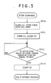
Fig. 5 is a flowchart illustrating operations performed when stopping the electric power generator; -
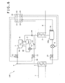
Fig. 6 is a diagram schematically illustrating the configuration of an electric power generator according to a third embodiment of the present invention. - Embodiments for carrying out the present invention will be described in detail hereinafter with reference to the drawings.
-
Fig. 1 illustrates the configuration of anelectric power generator 100 according to a first embodiment of a power generation apparatus according to the present invention. - The
electric power generator 100 includes a closed-loop circulating channel 6 in which are provided anexpander 1, anoil separator 2, a condenser (condensing means) 3, a workingmedium pump 4, and an evaporator (steam generator, steam generation means) 5. A Freon-based medium (for example, R245fa) is injected into the circulatingchannel 6 as a working medium. A medium with a lower boiling point than that of water is used, and theelectric power generator 100 according to the present embodiment is configured as a binary electric power generator. - The
expander 1 is disposed downstream from theevaporator 5 in the circulatingchannel 6, and obtains kinetic energy from the working medium by expanding the working medium evaporated by the evaporator 5 (vapor). Theexpander 1 is configured of, for example, a screw expander. This screw expander has a pair of male and female screw rotors (not shown) housed within a rotor chamber (not shown) formed in an expander casing, and rotates the screw rotors using the expansion force of the working medium supplied from anintake port 1s via the circulatingchannel 6. The working medium that has been expanded in the rotor chamber and whose pressure has dropped is then exhausted to the circulatingchannel 6 from anexhaust port 1d. - The
oil separator 2 is provided between theexpander 1 and thecondenser 3 in the circulatingchannel 6, and anoil flow channel 18 having anoil pump 17 is provided between theoil separator 2 and theexpander 1. Theoil separator 2 separates oil that is exhausted from theexpander 1 along with the working medium and holds the separated oil in its interior. The oil held in theoil separator 2 is supplied to the interior of theexpander 1 via theoil flow channel 18. The oil supplied to the interior of theexpander 1 functions as a sealant between the screw rotors and between the screw rotors and the rotor chamber, and works so as to prevent a drop in the efficiency of the expansion of the working medium. - An
electric generator 9 is connected to theexpander 1, and theelectric generator 9 is driven by the power generated by theexpander 1 being transmitted to theelectric generator 9. Theelectric generator 9 is configured so that a stator (not shown) and a rotor (not shown) are housed within the internal space of an electric generator casing (not shown). The rotor has a shaft that is integrated with the shaft of the screw rotors in theexpander 1, and by rotating along with the rotation of the screw rotors, causes a winding around the stator to generate electricity. Theexpander 1 and theelectric generator 9 configure an electricity generation means. - The
condenser 3 is disposed downstream from theexpander 1, and more specifically, is disposed downstream from theoil separator 2, in the circulatingchannel 6; the working medium that has been exhausted into the circulatingchannel 6 from theexhaust port 1d of theexpander 1, from which the oil has been separated and is thus in a gaseous state, is introduced into thecondenser 3. In thecondenser 3, the working medium is condensed through heat exchange with a coolant medium (for example, coolant water) that flows through acoolant medium channel 8 in a system separate from the circulatingchannel 6, thus becoming a liquid-state working medium. In other words, thecondenser 3 includes a channel through which the working medium flows and a channel through which the coolant medium flows, and condenses the working medium by instigating heat exchange between the gaseous working medium and the coolant medium. - The working medium that has become a liquid is pressurized by the
pump 4 to a predetermined pressure, and is then sent to theevaporator 5. - In the
evaporator 5, the working medium is heated through heat exchange with a thermal medium (for example, a low-pressure vapor) that flows through a thermalmedium channel 7 in a system separate from the circulatingchannel 6, thus becoming a saturated vapor (or a superheated vapor). In other words, theevaporator 5 includes a channel through which the working medium flows and a channel through which the thermal medium, which is supplied from an external heat source, flows, and vaporizes the working medium into a saturated vapor (or a superheated vapor) by instigating heat exchange between the working medium in a liquid state and the thermal medium. The working medium that has been turned into a saturated vapor (or a superheated vapor) by theevaporator 5 is once again supplied to theexpander 1. - In addition to vapor gathered from wells (steam wells) and excess heat exhausted from factories or the like, vapor generated by facilities such as a concentrator that uses solar heat as its heat source, a boiler that uses biomass, fossil fuels, and the like as its heat source, and so on can be considered as the thermal medium (heating medium) supplied to the
evaporator 5 via the thermalmedium channel 7. On the other hand, coolant water created by cooling towers can be considered as the coolant medium supplied to thecondenser 3 via thecoolant medium channel 8. - The
pump 4 is provided for circulating the working medium within the circulatingchannel 6, and is disposed downstream from thecondenser 3 in the circulatingchannel 6. In other words, thepump 4 is provided in the circulatingchannel 6 so as to connect thecondenser 3 and theevaporator 5, and takes in the working medium (liquid) from thecondenser 3 side and ejects the working medium to theevaporator 5 side. A centrifugal pump that uses an impeller as its rotor, a gear pump in which the rotor is configured of a pair of gears, or the like can be used favorably as thepump 4. - A first on/off valve 11 (V1) is provided between the
evaporator 5 and theexpander 1 in the circulatingchannel 6. Meanwhile, abypass channel 10 is provided in the circulatingchannel 6 so as to connect the area downstream from theevaporator 5 and the area upstream from thecondenser 3; more specifically, thebypass channel 10 is connected from between theevaporator 5 and the first on/offvalve 11 to between theexpander 1 and thecondenser 3. A second on/off valve 12 (V2) is provided in thebypass channel 10. Furthermore, a third on/off valve 13 (V3) is provided in the circulatingchannel 6 between thepump 4 and theevaporator 5. - A
check valve 14 that only allows a flow from theoil separator 2 to thecondenser 3 is provided upstream from thecondenser 3 in the circulatingchannel 6, in a location that is further upstream from the area where the circulatingchannel 6 and thebypass channel 10 are connected. In addition, acheck valve 15 that only allows a flow from the downstream side of theevaporator 5 toward the upstream of thecondenser 3 is provided downstream from the second on/offvalve 12 in thebypass channel 10. - The
electric power generator 100 includes a control unit (control means) 20. Thecontrol unit 20 includes an input/display means (not shown) such as a touch panel. Thecontrol unit 20 also includes a ROM, a RAM, a CPU, and so on, and can carry out predetermined functions by executing programs stored in the ROM. In other words, asetting unit 21, astart control unit 22, astop control unit 23, and adetermination unit 24 are included as functions of thecontrol unit 20. - The setting
unit 21 outputs a setting signal to the RAM so that a predetermined value of a timer, mentioned later, is set to a value inputted through the input/display means. The RAM receives the setting signal sent from the setting unit and stores the predetermined value. Thestart control unit 22 outputs a control signal for opening the first on/offvalve 11 and the third on/offvalve 13 and a control signal for starting theoil pump 17 and thepump 4 when a start command is generated through operations performed using the input/display means. Thestop control unit 23 outputs a control signal for closing the first on/offvalve 11, a control signal for stopping theoil pump 17 and thepump 4, and a control signal for closing the third on/offvalve 13, as well as a control signal for opening the second on/offvalve 12, when a stop command is generated through operations performed using the input/display means. Thedetermination unit 24 includes a timer that counts the time from when the start command is generated, and determines whether or not the timer value fulfills a predetermined condition set by the settingunit 21, or in other words, whether or not the predetermined value stored in the RAM has been reached. - Here, control operations performed when starting the
electric power generator 100 will be described with reference toFig. 2 . - When a start command is generated by the input/display means of the
control unit 20 being manipulated, thestart control unit 22 of thecontrol unit 20 opens the first on/offvalve 11 and the third on/off valve 13 (step ST1 and step ST2) and starts theoil pump 17 and the pump 4 (step ST3 and step ST4). Note that step ST1 through step ST4 may be carried out in any order, and may all be carried out simultaneously. - As a result, the liquid-state working medium sent from the
pump 4 is evaporated in theevaporator 5, becomes a saturated vapor (or a superheated vapor) as a result, is supplied to theexpander 1, and is expanded by theexpander 1. At this time, theelectric generator 9 obtains power from theexpander 1 and is driven as a result. The working medium exhausted from theexpander 1 is condensed by thecondenser 3, returns to a liquid state, and is taken in by thepump 4. The working medium is circulated through the circulatingchannel 6 in this manner. At this time, because the second on/offvalve 12 is a normally-closed on/off valve and is in a closed state at startup, the working medium does not flow through thebypass channel 10 at startup. - Next, control operations performed when stopping the
electric power generator 100 will be described with reference toFig. 3 . - When a stop command is generated by the input/display means of the
control unit 20 being manipulated, thestop control unit 23 of thecontrol unit 20 closes the first on/offvalve 11 and stops thepump 4 and oil pump 17 (step ST10), and also opens the second on/offvalve 12 and closes the third on/off valve 13 (step ST11). The timer in thedetermination unit 24 of thecontrol unit 20 is then started (step ST12). Note that step ST10 through step ST12 may be carried out in any order, and may all be carried out simultaneously. - After this, the
control unit 20 determines whether the value of the timer in thedetermination unit 24 has reached the predetermined value set in advance by the setting unit 21 (that is, determines whether or not a predetermined amount of time has passed after thepump 4 has been stopped, the second on/offvalve 12 has been opened, and the third on/offvalve 13 has been closed) (step ST13). - Step ST13 is repeated until the value of the timer reaches the predetermined value, and when it has been determined that the value of the timer has reached the predetermined value, the determination in step ST13 is YES, and the process moves to step ST14. Then, the second on/off
valve 12 is closed based on a control signal from the control unit 20 (step ST14), and the stopping process ends. - Now, the behavior of the working medium when the
pump 4 is stopped as described above will be discussed. When the first on/offvalve 11 and third on/offvalve 13 are closed and thepump 4 is stopped (step ST10, step ST11), the flow of the working medium is stopped in the section of the circulatingchannel 6 that spans from the exit of thecondenser 3 to the entrance of theevaporator 5. Through this, gaseous-state working medium and liquid-state working medium accumulate in both theevaporator 5 and thecondenser 3. At this time, the thermal medium continues to flow in the thermalmedium channel 7, and the coolant medium continues to flow in thecoolant medium channel 8. Accordingly, the working medium continues to be heated by the thermal medium in theevaporator 5, and thus the liquid-state working medium in theevaporator 5 continues to evaporate. As a result, the pressure within theevaporator 5 reaches a maximum vapor tension; for example, the temperature of the working medium within theevaporator 5 is 80°C, and a pressure P1 thereof is 0.789 MPa. On the other hand, the working medium continues to be cooled by the coolant medium in thecondenser 3, and thus the gaseous-state working medium in thecondenser 3 continues to condense. The temperature of the working medium within thecondenser 3 is, for example, 20°C, and a pressure P2 thereof is 0.124 MPa. At this time, the second on/offvalve 12 is open (step ST11), and thus due to the difference between the pressure in theevaporator 5 and the pressure in thecondenser 3, the working medium within theevaporator 5, which is primarily in a gaseous state, flows into thecondenser 3 through thebypass channel 10, and condenses in thecondenser 3. Furthermore, because the second on/offvalve 12 is opened only for the pre-set predetermined amount of time, a predetermined amount of liquid-state working medium accumulates in thecondenser 3 in that predetermined amount of time. Note that the predetermined amount of time changes depending on the size of theevaporator 5, the diameter and volume of the piping of the circulatingchannel 6 from thepump 4 to theevaporator 5, and so on. The predetermined amount of time is a time found through experimentation, analysis, or the like, and is a time that is set in advance by the settingunit 21 of thecontrol unit 20 as the amount of time required for the predetermined amount of working medium to accumulate in thecondenser 3 under a variety of conditions. - As described thus far, according to the present embodiment, after the second on/off
valve 12 is opened when stopping thepump 4, the working medium that has been heated by the thermal medium in theevaporator 5 and is thus in a gaseous state flows to thecondenser 3 through thebypass channel 10, is cooled by the coolant medium in thecondenser 3, and returns to a liquid state; thus by opening the second on/offvalve 12 for the predetermined amount of time until the predetermined amount of the liquid-state working medium has accumulated, the risk of cavitation occurring in the working medium taken in by thepump 4 can be reduced when starting thepump 4. -
Fig. 4 illustrates the configuration of anelectric power generator 100 according to a second embodiment of a power generation apparatus according to the present invention. Note that the second embodiment will describe only points that differ from the first embodiment, and descriptions of configurations, actions, and effects that are the same as in the first embodiment will be omitted. - In the
electric power generator 100 according to the second embodiment, in addition to the constituent elements of theelectric power generator 100 according to the first embodiment, thecondenser 3 is provided with a liquid surface meter (level gauge) 16 capable of detecting the height of the liquid surface therein. Furthermore, the settingunit 21 in thecontrol unit 20 outputs a setting signal to the RAM so that a predetermined value of the liquid surface meter (level gauge) 16 is set to a value inputted through the input/display means. Thedetermination unit 24 of the control unit determines whether or not the value detected by the liquid surface meter (level gauge) 16 fulfills a predetermined condition set in advance by the settingunit 21, or in other words, whether or not the predetermined value stored in the RAM has been reached. - Next, control operations performed in the present embodiment will be described. Here, control operations performed during stopping, which are different from those described in the first embodiment, will be described with reference to
Fig. 5 . - With the
electric power generator 100 according to the present embodiment, when stopping thepump 4, instead of step ST12 and step ST13 ofFig. 3 , which use the timer in the control operations performed when stopping theelectric power generator 100, step ST15, in which it is determined whether or not the detection value of the level gauge is greater than or equal to Hth (that is, whether or not the liquid surface has reached a predetermined liquid surface height), is executed. Here, Hth is a value found through experimentation, analysis, or the like, and is a value set in advance in thesetting unit 21 of thecontrol unit 20. - In other words, with the
electric power generator 100 according to the second embodiment, when a stop command is generated by the input/display means of thecontrol unit 20 being manipulated, thestop control unit 23 of thecontrol unit 20 closes the first on/offvalve 11 and stops thepump 4 and oil pump 17 (step ST10), and also opens the second on/offvalve 12 and closes the third on/off valve 13 (step ST11). Note that step ST10 and step ST11 may be carried out in any order, and may be carried out simultaneously. - After this, the
determination unit 24 of thecontrol unit 20 determines whether or not the value of the liquid surface meter (level gauge) 16 has reached the predetermined value Hth set in advance by the setting unit 21 (step ST15). - Step ST15 is repeated until the value of the liquid surface meter (level gauge) has reached the predetermined value Hth, and when it has been determined that the value of the liquid surface meter (level gauge) has reached the predetermined value Hth, the determination in step ST15, and the process moves to step ST14. Then, the second on/off
valve 12 is closed based on a control signal from the control unit 20 (step ST14), and the stopping process ends. - Although the behavior of the working medium when the
pump 4 is stopped as described above is the same in the present embodiment as in the first embodiment, in the present embodiment, it is objectively determined whether or not the channel upstream from thepump 4 is filled with liquid-state working medium based on the value detected by the liquid surface meter (level gauge) 16. Accordingly, a state where the channel upstream from thepump 4 is filled with liquid-state working medium can be ensured with more certainty than in the first embodiment, and the risk of cavitation occurring when starting the pump can be reduced even further. -
Fig. 6 illustrates the configuration of anelectric power generator 100 according to a third embodiment of a power generation apparatus according to the present invention. Note that the third embodiment will describe only points that differ from the second embodiment, and descriptions of configurations, actions, and effects that are the same as in the first embodiment and the second embodiment will be omitted. - In the
electric power generator 100 according to the third embodiment, in addition to the constituent elements of theelectric power generator 100 according to the second embodiment, aliquid tank 16a is provided in the circulatingchannel 6 between thecondenser 3 and thepump 4, and the liquid surface meter (level gauge) 16 is provided in theliquid tank 16a rather than in thecondenser 3. - The control operations performed when starting and stopping the
pump 4 of theelectric power generator 100 according to the present embodiment are the same as in the second embodiment. - Accordingly, in the present embodiment as well, a state where the channel upstream from the
pump 4 is filled with liquid-state working medium can be ensured with more certainty than in the first embodiment, and the risk of cavitation occurring when starting the pump can be reduced even further. Furthermore, because theliquid tank 16a is provided in the present embodiment, a greater amount of liquid working medium can be secured for the channel upstream from thepump 4 than in the second embodiment. - Note that the descriptions disclosed in the above embodiment are to be understood as being in all ways exemplary and in no way limiting. The scope of the present invention is defined by the appended claims rather than the descriptions of the aforementioned embodiments, and many modifications may be made within the same scope as the appended claims.
- For example, in the first through third embodiments, on/off valves may be provided in the thermal
medium channel 7 and thecoolant medium channel 8 in a manner that the on/off valves in thechannels valve 12 is opened. Alternatively, the on/off valves in the thermalmedium channel 7 and thecoolant medium channel 8 may be closed as thepump 4 is stopped. - Furthermore, the
oil separator 2 can be omitted depending on the type of theexpander 1. - Finally, the target of the driving performed by the power generation apparatus according to the present invention is not limited to electric generators.
- A power generation apparatus according to the present invention includes: a first on/off valve provided between a steam generation means and an expander in a circulating channel; a bypass channel connected between an area between the steam generation means and the first on/off valve and an area between the expander and a condensing means; a second on/off valve provided in the bypass channel; a third on/off valve provided between a pump and the steam generation means in the circulating channel; and a control means that carries out control for starting and stopping the pump and opening and closing the on/off valves. When stopping the pump, the control means outputs a control signal that stops the pump, a control signal that closes the first on/off valve, a control signal that opens the second on/off valve, and a control signal that closes the third on/off valve, and then, in the case where a predetermined condition has been met, outputs a control signal that closes the second on/off valve. With this configuration, the occurrence of cavitation in the pump that circulates the working medium can be suppressed without complicating the structure.
Claims (4)
- A power generation apparatus comprising:a steam generation means that evaporates a liquid working medium by heating the working medium using a thermal medium;an expander that expands the gaseous working medium and produces power as a result;a condensing means that condenses the gaseous working medium by cooling the working medium using a coolant medium;a pump that circulates the working medium;a closed-loop circulating channel in which said steam generation means, said expander, said condensing means, and said pump are connected in series;a first on/off valve provided in said circulating channel between said steam generation means and said expander;a bypass channel connected between an area in said circulating channel between said steam generation means and said first on/off valve and an area between said expander and said condensing means;a second on/off valve provided in said bypass channel;a third on/off valve provided in said circulating channel between said pump and said steam generation means; anda control means that carries out control for starting and stopping said pump and opening and closing said on/off valves,wherein when stopping said pump, said control means outputs a control signal that stops said pump, a control signal that closes said first on/off valve, a control signal that opens said second on/off valve, and a control signal that closes said third on/off valve, and then, in the case where a predetermined condition has been met, outputs a control signal that closes said second on/off valve.
- The power generation apparatus according to claim 1, wherein the predetermined condition is that an amount of time has been set in advance by said control means as an amount of time from when said second on/off valve is opened to when a predetermined amount of the liquid working medium has accumulated in said circulating channel upstream from said pump.
- The power generation apparatus according to claim 1, further comprising:a liquid surface meter, provided in said condensing means, that is capable of detecting a height of a liquid surface within said condensing means,wherein the predetermined condition is that a value of said liquid surface meter has reached a predetermined value.
- The power generation apparatus according to claim 1, further comprising:a liquid tank provided in said circulating channel between said condensing means and said pump and a liquid surface meter provided in said liquid tank, said liquid surface meter being capable of detecting a height of a liquid surface within said liquid tank,wherein the predetermined condition is that a value of said liquid surface meter has reached a predetermined value.
Applications Claiming Priority (1)
| Application Number | Priority Date | Filing Date | Title |
|---|---|---|---|
| JP2011129409A JP5597597B2 (en) | 2011-06-09 | 2011-06-09 | Power generator |
Publications (2)
| Publication Number | Publication Date |
|---|---|
| EP2532844A1 true EP2532844A1 (en) | 2012-12-12 |
| EP2532844B1 EP2532844B1 (en) | 2016-05-11 |
Family
ID=46148738
Family Applications (1)
| Application Number | Title | Priority Date | Filing Date |
|---|---|---|---|
| EP12169716.3A Not-in-force EP2532844B1 (en) | 2011-06-09 | 2012-05-29 | Power generation apparatus |
Country Status (5)
| Country | Link |
|---|---|
| US (1) | US8794001B2 (en) |
| EP (1) | EP2532844B1 (en) |
| JP (1) | JP5597597B2 (en) |
| KR (1) | KR101298821B1 (en) |
| CN (1) | CN102817649B (en) |
Cited By (1)
| Publication number | Priority date | Publication date | Assignee | Title |
|---|---|---|---|---|
| WO2014098843A1 (en) | 2012-12-19 | 2014-06-26 | Mack Trucks, Inc. | Apparatus and method of disabling a waste heat recovery apparatus working fluid flow |
Families Citing this family (20)
| Publication number | Priority date | Publication date | Assignee | Title |
|---|---|---|---|---|
| JP5715111B2 (en) * | 2012-12-12 | 2015-05-07 | 株式会社神戸製鋼所 | Power generation device and power generation system |
| JP5964229B2 (en) * | 2012-12-28 | 2016-08-03 | 三菱重工業株式会社 | Power generation system |
| NO335230B1 (en) * | 2013-02-19 | 2014-10-27 | Viking Heat Engines As | Device and method of operation and safety control of a heat power machine |
| JP2014171350A (en) * | 2013-03-05 | 2014-09-18 | Kobe Steel Ltd | Power generation device and power generation method |
| JP5957410B2 (en) | 2013-04-16 | 2016-07-27 | 株式会社神戸製鋼所 | Waste heat recovery device |
| JP6060040B2 (en) * | 2013-06-07 | 2017-01-11 | 株式会社神戸製鋼所 | Waste heat recovery device and operation control method of waste heat recovery device |
| US10060302B2 (en) * | 2013-10-21 | 2018-08-28 | Shanghai Jiaotong University | Passive low temperature heat sources organic working fluid power generation method |
| DE102014202487A1 (en) * | 2014-02-12 | 2015-08-13 | Robert Bosch Gmbh | Control unit, heat coupling circuit and method for operating such a heat coupling circuit |
| JP2015214922A (en) * | 2014-05-09 | 2015-12-03 | 株式会社神戸製鋼所 | Thermal energy recovery device and start method of the same |
| JP6423614B2 (en) * | 2014-05-13 | 2018-11-14 | 株式会社神戸製鋼所 | Thermal energy recovery device |
| JP6198673B2 (en) | 2014-05-15 | 2017-09-20 | 株式会社神戸製鋼所 | Thermal energy recovery device and control method |
| JP6190319B2 (en) * | 2014-05-22 | 2017-08-30 | 株式会社神戸製鋼所 | Thermal energy recovery device |
| CN104314631A (en) * | 2014-08-15 | 2015-01-28 | 国核柏斯顿新能源科技(北京)有限公司 | System for generating power in non heating season by low-temperature nuclear heat reactor and working method of system |
| JP6616235B2 (en) * | 2016-05-10 | 2019-12-04 | 株式会社神戸製鋼所 | Waste heat recovery system |
| CN105806093B (en) * | 2016-05-12 | 2017-12-26 | 张育仁 | A kind of temperature difference power cooling tower based on screw expander |
| JP2018009458A (en) * | 2016-07-11 | 2018-01-18 | 株式会社Ihi | Binary power generation system and actuation medium pump |
| JP6763797B2 (en) * | 2017-02-08 | 2020-09-30 | 株式会社神戸製鋼所 | Binary power generation system |
| JP6769888B2 (en) * | 2017-02-09 | 2020-10-14 | 株式会社神戸製鋼所 | Thermal energy recovery device |
| JP6763848B2 (en) * | 2017-12-04 | 2020-09-30 | 株式会社神戸製鋼所 | Thermal energy recovery device |
| GB2581770B (en) * | 2019-01-14 | 2023-01-18 | Gas Expansion Motors Ltd | Engine |
Citations (4)
| Publication number | Priority date | Publication date | Assignee | Title |
|---|---|---|---|---|
| DE10004187C1 (en) * | 2000-02-01 | 2001-10-18 | Siemens Ag | Gas-and-steam turbine plant operating method |
| US20050183421A1 (en) * | 2002-02-25 | 2005-08-25 | Kirell, Inc., Dba H & R Consulting. | System and method for generation of electricity and power from waste heat and solar sources |
| US20060112693A1 (en) * | 2004-11-30 | 2006-06-01 | Sundel Timothy N | Method and apparatus for power generation using waste heat |
| JP4557793B2 (en) | 2005-05-16 | 2010-10-06 | 株式会社荏原製作所 | Waste heat power generator |
Family Cites Families (11)
| Publication number | Priority date | Publication date | Assignee | Title |
|---|---|---|---|---|
| DE3509072A1 (en) * | 1985-03-14 | 1986-09-25 | Klaus Dipl.-Ing.(FH) 3200 Hildesheim Metzger | METHOD FOR SETTING THE CAVITATION |
| JPH08135404A (en) * | 1994-11-07 | 1996-05-28 | Toshiba Corp | Bypass steam introduction method for condenser and turbine plant |
| US20030213246A1 (en) * | 2002-05-15 | 2003-11-20 | Coll John Gordon | Process and device for controlling the thermal and electrical output of integrated micro combined heat and power generation systems |
| EP1441121A2 (en) * | 2003-01-27 | 2004-07-28 | Denso Corporation | Vapor-compression refrigerant cycle system with refrigeration cycle and rankine cycle |
| JP2008008217A (en) * | 2006-06-29 | 2008-01-17 | Ebara Corp | Power generator |
| US8528333B2 (en) * | 2007-03-02 | 2013-09-10 | Victor Juchymenko | Controlled organic rankine cycle system for recovery and conversion of thermal energy |
| JP4302759B2 (en) * | 2007-09-14 | 2009-07-29 | 株式会社デンソー | Waste heat utilization equipment |
| US7950230B2 (en) * | 2007-09-14 | 2011-05-31 | Denso Corporation | Waste heat recovery apparatus |
| CN201314546Y (en) * | 2008-10-17 | 2009-09-23 | 山东中德设备有限公司 | Condensate water reclaimer under pressure |
| CN103180554B (en) * | 2010-08-13 | 2016-01-20 | 康明斯知识产权公司 | Rankine Cycle Condenser Pressure Control Using Transducer Bypass Valve |
| JP5596631B2 (en) | 2011-06-30 | 2014-09-24 | 株式会社神戸製鋼所 | Binary power generator |
-
2011
- 2011-06-09 JP JP2011129409A patent/JP5597597B2/en not_active Expired - Fee Related
-
2012
- 2012-05-15 US US13/471,830 patent/US8794001B2/en not_active Expired - Fee Related
- 2012-05-29 EP EP12169716.3A patent/EP2532844B1/en not_active Not-in-force
- 2012-06-05 KR KR1020120060486A patent/KR101298821B1/en not_active Expired - Fee Related
- 2012-06-08 CN CN201210187912.5A patent/CN102817649B/en not_active Expired - Fee Related
Patent Citations (4)
| Publication number | Priority date | Publication date | Assignee | Title |
|---|---|---|---|---|
| DE10004187C1 (en) * | 2000-02-01 | 2001-10-18 | Siemens Ag | Gas-and-steam turbine plant operating method |
| US20050183421A1 (en) * | 2002-02-25 | 2005-08-25 | Kirell, Inc., Dba H & R Consulting. | System and method for generation of electricity and power from waste heat and solar sources |
| US20060112693A1 (en) * | 2004-11-30 | 2006-06-01 | Sundel Timothy N | Method and apparatus for power generation using waste heat |
| JP4557793B2 (en) | 2005-05-16 | 2010-10-06 | 株式会社荏原製作所 | Waste heat power generator |
Cited By (2)
| Publication number | Priority date | Publication date | Assignee | Title |
|---|---|---|---|---|
| WO2014098843A1 (en) | 2012-12-19 | 2014-06-26 | Mack Trucks, Inc. | Apparatus and method of disabling a waste heat recovery apparatus working fluid flow |
| EP2935818A4 (en) * | 2012-12-19 | 2016-07-27 | Mack Trucks | Apparatus and method of disabling a waste heat recovery apparatus working fluid flow |
Also Published As
| Publication number | Publication date |
|---|---|
| EP2532844B1 (en) | 2016-05-11 |
| CN102817649B (en) | 2015-05-13 |
| CN102817649A (en) | 2012-12-12 |
| JP5597597B2 (en) | 2014-10-01 |
| KR101298821B1 (en) | 2013-08-23 |
| KR20120137251A (en) | 2012-12-20 |
| US8794001B2 (en) | 2014-08-05 |
| US20120312021A1 (en) | 2012-12-13 |
| JP2012255400A (en) | 2012-12-27 |
Similar Documents
| Publication | Publication Date | Title |
|---|---|---|
| EP2532844B1 (en) | Power generation apparatus | |
| KR101482877B1 (en) | Power generation apparatus and control method thereof | |
| KR101482879B1 (en) | Power generating apparatus and operation method thereof | |
| EP2940255B1 (en) | Power generation system, power generation method | |
| KR101361253B1 (en) | Power generating apparatus | |
| KR101442425B1 (en) | System combining power generation apparatus and desalination apparatus | |
| KR101325350B1 (en) | Power generating apparatus | |
| US20150322821A1 (en) | Thermal energy recovery device and start-up method of thermal energy recovery device | |
| US20150377075A1 (en) | Recovery system using fluid coupling on power generating system | |
| JP5827480B2 (en) | Power generator | |
| JP6060029B2 (en) | Rotating machine drive system | |
| KR101482876B1 (en) | Power generation apparatus and control method thereof | |
| JP2011157855A (en) | Power generation facility and operating method for power generation facility | |
| US9358498B2 (en) | Mixed air removal device and power generator including the same | |
| JP5671442B2 (en) | Thermal energy utilization apparatus and operation method thereof | |
| CN105822369B (en) | A kind of control method of organic Rankine cycle power generation system | |
| KR101644547B1 (en) | Power generation plant including auxiliary power generation system |
Legal Events
| Date | Code | Title | Description |
|---|---|---|---|
| PUAI | Public reference made under article 153(3) epc to a published international application that has entered the european phase |
Free format text: ORIGINAL CODE: 0009012 |
|
| 17P | Request for examination filed |
Effective date: 20120529 |
|
| AK | Designated contracting states |
Kind code of ref document: A1 Designated state(s): AL AT BE BG CH CY CZ DE DK EE ES FI FR GB GR HR HU IE IS IT LI LT LU LV MC MK MT NL NO PL PT RO RS SE SI SK SM TR |
|
| AX | Request for extension of the european patent |
Extension state: BA ME |
|
| GRAP | Despatch of communication of intention to grant a patent |
Free format text: ORIGINAL CODE: EPIDOSNIGR1 |
|
| RIC1 | Information provided on ipc code assigned before grant |
Ipc: F01K 13/02 20060101AFI20151028BHEP |
|
| INTG | Intention to grant announced |
Effective date: 20151130 |
|
| GRAS | Grant fee paid |
Free format text: ORIGINAL CODE: EPIDOSNIGR3 |
|
| GRAA | (expected) grant |
Free format text: ORIGINAL CODE: 0009210 |
|
| AK | Designated contracting states |
Kind code of ref document: B1 Designated state(s): AL AT BE BG CH CY CZ DE DK EE ES FI FR GB GR HR HU IE IS IT LI LT LU LV MC MK MT NL NO PL PT RO RS SE SI SK SM TR |
|
| REG | Reference to a national code |
Ref country code: GB Ref legal event code: FG4D |
|
| REG | Reference to a national code |
Ref country code: CH Ref legal event code: EP |
|
| REG | Reference to a national code |
Ref country code: AT Ref legal event code: REF Ref document number: 798855 Country of ref document: AT Kind code of ref document: T Effective date: 20160515 |
|
| REG | Reference to a national code |
Ref country code: IE Ref legal event code: FG4D |
|
| REG | Reference to a national code |
Ref country code: FR Ref legal event code: PLFP Year of fee payment: 5 |
|
| REG | Reference to a national code |
Ref country code: DE Ref legal event code: R096 Ref document number: 602012018273 Country of ref document: DE |
|
| REG | Reference to a national code |
Ref country code: SE Ref legal event code: TRGR |
|
| REG | Reference to a national code |
Ref country code: LT Ref legal event code: MG4D |
|
| REG | Reference to a national code |
Ref country code: NL Ref legal event code: MP Effective date: 20160511 |
|
| PG25 | Lapsed in a contracting state [announced via postgrant information from national office to epo] |
Ref country code: LT Free format text: LAPSE BECAUSE OF FAILURE TO SUBMIT A TRANSLATION OF THE DESCRIPTION OR TO PAY THE FEE WITHIN THE PRESCRIBED TIME-LIMIT Effective date: 20160511 Ref country code: NO Free format text: LAPSE BECAUSE OF FAILURE TO SUBMIT A TRANSLATION OF THE DESCRIPTION OR TO PAY THE FEE WITHIN THE PRESCRIBED TIME-LIMIT Effective date: 20160811 Ref country code: FI Free format text: LAPSE BECAUSE OF FAILURE TO SUBMIT A TRANSLATION OF THE DESCRIPTION OR TO PAY THE FEE WITHIN THE PRESCRIBED TIME-LIMIT Effective date: 20160511 Ref country code: NL Free format text: LAPSE BECAUSE OF FAILURE TO SUBMIT A TRANSLATION OF THE DESCRIPTION OR TO PAY THE FEE WITHIN THE PRESCRIBED TIME-LIMIT Effective date: 20160511 |
|
| REG | Reference to a national code |
Ref country code: AT Ref legal event code: MK05 Ref document number: 798855 Country of ref document: AT Kind code of ref document: T Effective date: 20160511 |
|
| PG25 | Lapsed in a contracting state [announced via postgrant information from national office to epo] |
Ref country code: PT Free format text: LAPSE BECAUSE OF FAILURE TO SUBMIT A TRANSLATION OF THE DESCRIPTION OR TO PAY THE FEE WITHIN THE PRESCRIBED TIME-LIMIT Effective date: 20160912 Ref country code: RS Free format text: LAPSE BECAUSE OF FAILURE TO SUBMIT A TRANSLATION OF THE DESCRIPTION OR TO PAY THE FEE WITHIN THE PRESCRIBED TIME-LIMIT Effective date: 20160511 Ref country code: GR Free format text: LAPSE BECAUSE OF FAILURE TO SUBMIT A TRANSLATION OF THE DESCRIPTION OR TO PAY THE FEE WITHIN THE PRESCRIBED TIME-LIMIT Effective date: 20160812 Ref country code: ES Free format text: LAPSE BECAUSE OF FAILURE TO SUBMIT A TRANSLATION OF THE DESCRIPTION OR TO PAY THE FEE WITHIN THE PRESCRIBED TIME-LIMIT Effective date: 20160511 Ref country code: HR Free format text: LAPSE BECAUSE OF FAILURE TO SUBMIT A TRANSLATION OF THE DESCRIPTION OR TO PAY THE FEE WITHIN THE PRESCRIBED TIME-LIMIT Effective date: 20160511 Ref country code: LV Free format text: LAPSE BECAUSE OF FAILURE TO SUBMIT A TRANSLATION OF THE DESCRIPTION OR TO PAY THE FEE WITHIN THE PRESCRIBED TIME-LIMIT Effective date: 20160511 |
|
| PG25 | Lapsed in a contracting state [announced via postgrant information from national office to epo] |
Ref country code: IT Free format text: LAPSE BECAUSE OF FAILURE TO SUBMIT A TRANSLATION OF THE DESCRIPTION OR TO PAY THE FEE WITHIN THE PRESCRIBED TIME-LIMIT Effective date: 20160511 Ref country code: BE Free format text: LAPSE BECAUSE OF NON-PAYMENT OF DUE FEES Effective date: 20160531 |
|
| REG | Reference to a national code |
Ref country code: CH Ref legal event code: PL |
|
| PG25 | Lapsed in a contracting state [announced via postgrant information from national office to epo] |
Ref country code: LI Free format text: LAPSE BECAUSE OF NON-PAYMENT OF DUE FEES Effective date: 20160531 Ref country code: DK Free format text: LAPSE BECAUSE OF FAILURE TO SUBMIT A TRANSLATION OF THE DESCRIPTION OR TO PAY THE FEE WITHIN THE PRESCRIBED TIME-LIMIT Effective date: 20160511 Ref country code: SK Free format text: LAPSE BECAUSE OF FAILURE TO SUBMIT A TRANSLATION OF THE DESCRIPTION OR TO PAY THE FEE WITHIN THE PRESCRIBED TIME-LIMIT Effective date: 20160511 Ref country code: RO Free format text: LAPSE BECAUSE OF FAILURE TO SUBMIT A TRANSLATION OF THE DESCRIPTION OR TO PAY THE FEE WITHIN THE PRESCRIBED TIME-LIMIT Effective date: 20160511 Ref country code: CZ Free format text: LAPSE BECAUSE OF FAILURE TO SUBMIT A TRANSLATION OF THE DESCRIPTION OR TO PAY THE FEE WITHIN THE PRESCRIBED TIME-LIMIT Effective date: 20160511 Ref country code: CH Free format text: LAPSE BECAUSE OF NON-PAYMENT OF DUE FEES Effective date: 20160531 Ref country code: EE Free format text: LAPSE BECAUSE OF FAILURE TO SUBMIT A TRANSLATION OF THE DESCRIPTION OR TO PAY THE FEE WITHIN THE PRESCRIBED TIME-LIMIT Effective date: 20160511 |
|
| REG | Reference to a national code |
Ref country code: DE Ref legal event code: R097 Ref document number: 602012018273 Country of ref document: DE |
|
| REG | Reference to a national code |
Ref country code: IE Ref legal event code: MM4A |
|
| PG25 | Lapsed in a contracting state [announced via postgrant information from national office to epo] |
Ref country code: SM Free format text: LAPSE BECAUSE OF FAILURE TO SUBMIT A TRANSLATION OF THE DESCRIPTION OR TO PAY THE FEE WITHIN THE PRESCRIBED TIME-LIMIT Effective date: 20160511 Ref country code: PL Free format text: LAPSE BECAUSE OF FAILURE TO SUBMIT A TRANSLATION OF THE DESCRIPTION OR TO PAY THE FEE WITHIN THE PRESCRIBED TIME-LIMIT Effective date: 20160511 Ref country code: BE Free format text: LAPSE BECAUSE OF FAILURE TO SUBMIT A TRANSLATION OF THE DESCRIPTION OR TO PAY THE FEE WITHIN THE PRESCRIBED TIME-LIMIT Effective date: 20160511 Ref country code: AT Free format text: LAPSE BECAUSE OF FAILURE TO SUBMIT A TRANSLATION OF THE DESCRIPTION OR TO PAY THE FEE WITHIN THE PRESCRIBED TIME-LIMIT Effective date: 20160511 |
|
| PLBE | No opposition filed within time limit |
Free format text: ORIGINAL CODE: 0009261 |
|
| STAA | Information on the status of an ep patent application or granted ep patent |
Free format text: STATUS: NO OPPOSITION FILED WITHIN TIME LIMIT |
|
| PG25 | Lapsed in a contracting state [announced via postgrant information from national office to epo] |
Ref country code: MC Free format text: LAPSE BECAUSE OF FAILURE TO SUBMIT A TRANSLATION OF THE DESCRIPTION OR TO PAY THE FEE WITHIN THE PRESCRIBED TIME-LIMIT Effective date: 20160511 |
|
| REG | Reference to a national code |
Ref country code: FR Ref legal event code: PLFP Year of fee payment: 6 |
|
| 26N | No opposition filed |
Effective date: 20170214 |
|
| GBPC | Gb: european patent ceased through non-payment of renewal fee |
Effective date: 20160811 |
|
| PG25 | Lapsed in a contracting state [announced via postgrant information from national office to epo] |
Ref country code: IE Free format text: LAPSE BECAUSE OF NON-PAYMENT OF DUE FEES Effective date: 20160529 Ref country code: SI Free format text: LAPSE BECAUSE OF FAILURE TO SUBMIT A TRANSLATION OF THE DESCRIPTION OR TO PAY THE FEE WITHIN THE PRESCRIBED TIME-LIMIT Effective date: 20160511 |
|
| PG25 | Lapsed in a contracting state [announced via postgrant information from national office to epo] |
Ref country code: GB Free format text: LAPSE BECAUSE OF NON-PAYMENT OF DUE FEES Effective date: 20160811 |
|
| REG | Reference to a national code |
Ref country code: FR Ref legal event code: PLFP Year of fee payment: 7 |
|
| PG25 | Lapsed in a contracting state [announced via postgrant information from national office to epo] |
Ref country code: CY Free format text: LAPSE BECAUSE OF FAILURE TO SUBMIT A TRANSLATION OF THE DESCRIPTION OR TO PAY THE FEE WITHIN THE PRESCRIBED TIME-LIMIT Effective date: 20160511 Ref country code: HU Free format text: LAPSE BECAUSE OF FAILURE TO SUBMIT A TRANSLATION OF THE DESCRIPTION OR TO PAY THE FEE WITHIN THE PRESCRIBED TIME-LIMIT; INVALID AB INITIO Effective date: 20120529 |
|
| PG25 | Lapsed in a contracting state [announced via postgrant information from national office to epo] |
Ref country code: MK Free format text: LAPSE BECAUSE OF FAILURE TO SUBMIT A TRANSLATION OF THE DESCRIPTION OR TO PAY THE FEE WITHIN THE PRESCRIBED TIME-LIMIT Effective date: 20160511 Ref country code: IS Free format text: LAPSE BECAUSE OF FAILURE TO SUBMIT A TRANSLATION OF THE DESCRIPTION OR TO PAY THE FEE WITHIN THE PRESCRIBED TIME-LIMIT Effective date: 20160511 Ref country code: MT Free format text: LAPSE BECAUSE OF NON-PAYMENT OF DUE FEES Effective date: 20160531 Ref country code: TR Free format text: LAPSE BECAUSE OF FAILURE TO SUBMIT A TRANSLATION OF THE DESCRIPTION OR TO PAY THE FEE WITHIN THE PRESCRIBED TIME-LIMIT Effective date: 20160511 Ref country code: LU Free format text: LAPSE BECAUSE OF NON-PAYMENT OF DUE FEES Effective date: 20160529 |
|
| PG25 | Lapsed in a contracting state [announced via postgrant information from national office to epo] |
Ref country code: BG Free format text: LAPSE BECAUSE OF FAILURE TO SUBMIT A TRANSLATION OF THE DESCRIPTION OR TO PAY THE FEE WITHIN THE PRESCRIBED TIME-LIMIT Effective date: 20160511 |
|
| PG25 | Lapsed in a contracting state [announced via postgrant information from national office to epo] |
Ref country code: AL Free format text: LAPSE BECAUSE OF FAILURE TO SUBMIT A TRANSLATION OF THE DESCRIPTION OR TO PAY THE FEE WITHIN THE PRESCRIBED TIME-LIMIT Effective date: 20160511 |
|
| PGFP | Annual fee paid to national office [announced via postgrant information from national office to epo] |
Ref country code: DE Payment date: 20190514 Year of fee payment: 8 |
|
| PGFP | Annual fee paid to national office [announced via postgrant information from national office to epo] |
Ref country code: SE Payment date: 20190513 Year of fee payment: 8 Ref country code: FR Payment date: 20190410 Year of fee payment: 8 |
|
| REG | Reference to a national code |
Ref country code: DE Ref legal event code: R119 Ref document number: 602012018273 Country of ref document: DE |
|
| PG25 | Lapsed in a contracting state [announced via postgrant information from national office to epo] |
Ref country code: SE Free format text: LAPSE BECAUSE OF NON-PAYMENT OF DUE FEES Effective date: 20200530 |
|
| PG25 | Lapsed in a contracting state [announced via postgrant information from national office to epo] |
Ref country code: FR Free format text: LAPSE BECAUSE OF NON-PAYMENT OF DUE FEES Effective date: 20200531 |
|
| PG25 | Lapsed in a contracting state [announced via postgrant information from national office to epo] |
Ref country code: DE Free format text: LAPSE BECAUSE OF NON-PAYMENT OF DUE FEES Effective date: 20201201 |