EP2532819A1 - Türrahmen - Google Patents
Türrahmen Download PDFInfo
- Publication number
- EP2532819A1 EP2532819A1 EP12002729A EP12002729A EP2532819A1 EP 2532819 A1 EP2532819 A1 EP 2532819A1 EP 12002729 A EP12002729 A EP 12002729A EP 12002729 A EP12002729 A EP 12002729A EP 2532819 A1 EP2532819 A1 EP 2532819A1
- Authority
- EP
- European Patent Office
- Prior art keywords
- frame profile
- slide rail
- door frame
- frame
- door
- Prior art date
- Legal status (The legal status is an assumption and is not a legal conclusion. Google has not performed a legal analysis and makes no representation as to the accuracy of the status listed.)
- Withdrawn
Links
- 239000004033 plastic Substances 0.000 claims abstract description 11
- 230000005540 biological transmission Effects 0.000 claims abstract description 6
- 238000001125 extrusion Methods 0.000 claims abstract description 4
- 238000000034 method Methods 0.000 claims abstract description 4
- 239000002991 molded plastic Substances 0.000 claims 1
- 238000003801 milling Methods 0.000 description 3
- 241000238631 Hexapoda Species 0.000 description 2
- XAGFODPZIPBFFR-UHFFFAOYSA-N aluminium Chemical compound [Al] XAGFODPZIPBFFR-UHFFFAOYSA-N 0.000 description 2
- 229910052782 aluminium Inorganic materials 0.000 description 2
- 238000011161 development Methods 0.000 description 2
- 230000018109 developmental process Effects 0.000 description 2
- 238000009413 insulation Methods 0.000 description 2
- 230000010354 integration Effects 0.000 description 2
- 238000004519 manufacturing process Methods 0.000 description 2
- 238000000926 separation method Methods 0.000 description 2
- 229910000831 Steel Inorganic materials 0.000 description 1
- 150000001875 compounds Chemical class 0.000 description 1
- 238000010276 construction Methods 0.000 description 1
- 239000000356 contaminant Substances 0.000 description 1
- 238000011109 contamination Methods 0.000 description 1
- 230000001419 dependent effect Effects 0.000 description 1
- 238000012986 modification Methods 0.000 description 1
- 230000004048 modification Effects 0.000 description 1
- 230000035515 penetration Effects 0.000 description 1
- 239000010959 steel Substances 0.000 description 1
- 239000002023 wood Substances 0.000 description 1
Images


Classifications
-
- E—FIXED CONSTRUCTIONS
- E05—LOCKS; KEYS; WINDOW OR DOOR FITTINGS; SAFES
- E05F—DEVICES FOR MOVING WINGS INTO OPEN OR CLOSED POSITION; CHECKS FOR WINGS; WING FITTINGS NOT OTHERWISE PROVIDED FOR, CONCERNED WITH THE FUNCTIONING OF THE WING
- E05F3/00—Closers or openers with braking devices, e.g. checks; Construction of pneumatic or liquid braking devices
- E05F3/22—Additional arrangements for closers, e.g. for holding the wing in opened or other position
-
- E—FIXED CONSTRUCTIONS
- E05—LOCKS; KEYS; WINDOW OR DOOR FITTINGS; SAFES
- E05F—DEVICES FOR MOVING WINGS INTO OPEN OR CLOSED POSITION; CHECKS FOR WINGS; WING FITTINGS NOT OTHERWISE PROVIDED FOR, CONCERNED WITH THE FUNCTIONING OF THE WING
- E05F3/00—Closers or openers with braking devices, e.g. checks; Construction of pneumatic or liquid braking devices
- E05F3/22—Additional arrangements for closers, e.g. for holding the wing in opened or other position
- E05F3/227—Additional arrangements for closers, e.g. for holding the wing in opened or other position mounted at the top of wings, e.g. details related to closer housings, covers, end caps or rails therefor
-
- E—FIXED CONSTRUCTIONS
- E06—DOORS, WINDOWS, SHUTTERS, OR ROLLER BLINDS IN GENERAL; LADDERS
- E06B—FIXED OR MOVABLE CLOSURES FOR OPENINGS IN BUILDINGS, VEHICLES, FENCES OR LIKE ENCLOSURES IN GENERAL, e.g. DOORS, WINDOWS, BLINDS, GATES
- E06B1/00—Border constructions of openings in walls, floors, or ceilings; Frames to be rigidly mounted in such openings
- E06B1/04—Frames for doors, windows, or the like to be fixed in openings
- E06B1/32—Frames composed of parts made of different materials
- E06B1/325—Frames composed of parts made of different materials comprising insulation between two metal section members
-
- E—FIXED CONSTRUCTIONS
- E05—LOCKS; KEYS; WINDOW OR DOOR FITTINGS; SAFES
- E05F—DEVICES FOR MOVING WINGS INTO OPEN OR CLOSED POSITION; CHECKS FOR WINGS; WING FITTINGS NOT OTHERWISE PROVIDED FOR, CONCERNED WITH THE FUNCTIONING OF THE WING
- E05F3/00—Closers or openers with braking devices, e.g. checks; Construction of pneumatic or liquid braking devices
- E05F3/22—Additional arrangements for closers, e.g. for holding the wing in opened or other position
- E05F2003/228—Arrangements where the end of the closer arm is sliding in a track
-
- E—FIXED CONSTRUCTIONS
- E05—LOCKS; KEYS; WINDOW OR DOOR FITTINGS; SAFES
- E05Y—INDEXING SCHEME ASSOCIATED WITH SUBCLASSES E05D AND E05F, RELATING TO CONSTRUCTION ELEMENTS, ELECTRIC CONTROL, POWER SUPPLY, POWER SIGNAL OR TRANSMISSION, USER INTERFACES, MOUNTING OR COUPLING, DETAILS, ACCESSORIES, AUXILIARY OPERATIONS NOT OTHERWISE PROVIDED FOR, APPLICATION THEREOF
- E05Y2800/00—Details, accessories and auxiliary operations not otherwise provided for
- E05Y2800/26—Form or shape
- E05Y2800/29—Form or shape forming a unitary piece with another element
-
- E—FIXED CONSTRUCTIONS
- E05—LOCKS; KEYS; WINDOW OR DOOR FITTINGS; SAFES
- E05Y—INDEXING SCHEME ASSOCIATED WITH SUBCLASSES E05D AND E05F, RELATING TO CONSTRUCTION ELEMENTS, ELECTRIC CONTROL, POWER SUPPLY, POWER SIGNAL OR TRANSMISSION, USER INTERFACES, MOUNTING OR COUPLING, DETAILS, ACCESSORIES, AUXILIARY OPERATIONS NOT OTHERWISE PROVIDED FOR, APPLICATION THEREOF
- E05Y2800/00—Details, accessories and auxiliary operations not otherwise provided for
- E05Y2800/352—Frames; Posts
- E05Y2800/353—Frames; Posts fixed
- E05Y2800/356—Frames; Posts fixed horizontal frame members
-
- E—FIXED CONSTRUCTIONS
- E05—LOCKS; KEYS; WINDOW OR DOOR FITTINGS; SAFES
- E05Y—INDEXING SCHEME ASSOCIATED WITH SUBCLASSES E05D AND E05F, RELATING TO CONSTRUCTION ELEMENTS, ELECTRIC CONTROL, POWER SUPPLY, POWER SIGNAL OR TRANSMISSION, USER INTERFACES, MOUNTING OR COUPLING, DETAILS, ACCESSORIES, AUXILIARY OPERATIONS NOT OTHERWISE PROVIDED FOR, APPLICATION THEREOF
- E05Y2800/00—Details, accessories and auxiliary operations not otherwise provided for
- E05Y2800/45—Manufacturing
- E05Y2800/455—Extrusion
-
- E—FIXED CONSTRUCTIONS
- E05—LOCKS; KEYS; WINDOW OR DOOR FITTINGS; SAFES
- E05Y—INDEXING SCHEME ASSOCIATED WITH SUBCLASSES E05D AND E05F, RELATING TO CONSTRUCTION ELEMENTS, ELECTRIC CONTROL, POWER SUPPLY, POWER SIGNAL OR TRANSMISSION, USER INTERFACES, MOUNTING OR COUPLING, DETAILS, ACCESSORIES, AUXILIARY OPERATIONS NOT OTHERWISE PROVIDED FOR, APPLICATION THEREOF
- E05Y2900/00—Application of doors, windows, wings or fittings thereof
- E05Y2900/10—Application of doors, windows, wings or fittings thereof for buildings or parts thereof
- E05Y2900/13—Type of wing
- E05Y2900/132—Doors
-
- E—FIXED CONSTRUCTIONS
- E06—DOORS, WINDOWS, SHUTTERS, OR ROLLER BLINDS IN GENERAL; LADDERS
- E06B—FIXED OR MOVABLE CLOSURES FOR OPENINGS IN BUILDINGS, VEHICLES, FENCES OR LIKE ENCLOSURES IN GENERAL, e.g. DOORS, WINDOWS, BLINDS, GATES
- E06B3/00—Window sashes, door leaves, or like elements for closing wall or like openings; Layout of fixed or moving closures, e.g. windows in wall or like openings; Features of rigidly-mounted outer frames relating to the mounting of wing frames
- E06B3/04—Wing frames not characterised by the manner of movement
- E06B3/263—Frames with special provision for insulation
- E06B2003/26349—Details of insulating strips
- E06B2003/2635—Specific form characteristics
- E06B2003/26352—Specific form characteristics hollow
-
- E—FIXED CONSTRUCTIONS
- E06—DOORS, WINDOWS, SHUTTERS, OR ROLLER BLINDS IN GENERAL; LADDERS
- E06B—FIXED OR MOVABLE CLOSURES FOR OPENINGS IN BUILDINGS, VEHICLES, FENCES OR LIKE ENCLOSURES IN GENERAL, e.g. DOORS, WINDOWS, BLINDS, GATES
- E06B3/00—Window sashes, door leaves, or like elements for closing wall or like openings; Layout of fixed or moving closures, e.g. windows in wall or like openings; Features of rigidly-mounted outer frames relating to the mounting of wing frames
- E06B3/04—Wing frames not characterised by the manner of movement
- E06B3/263—Frames with special provision for insulation
- E06B2003/26349—Details of insulating strips
- E06B2003/2635—Specific form characteristics
- E06B2003/26361—Openings, incisions or indents
-
- E—FIXED CONSTRUCTIONS
- E06—DOORS, WINDOWS, SHUTTERS, OR ROLLER BLINDS IN GENERAL; LADDERS
- E06B—FIXED OR MOVABLE CLOSURES FOR OPENINGS IN BUILDINGS, VEHICLES, FENCES OR LIKE ENCLOSURES IN GENERAL, e.g. DOORS, WINDOWS, BLINDS, GATES
- E06B3/00—Window sashes, door leaves, or like elements for closing wall or like openings; Layout of fixed or moving closures, e.g. windows in wall or like openings; Features of rigidly-mounted outer frames relating to the mounting of wing frames
- E06B3/04—Wing frames not characterised by the manner of movement
- E06B3/263—Frames with special provision for insulation
- E06B2003/26349—Details of insulating strips
- E06B2003/26387—Performing extra functions
-
- E—FIXED CONSTRUCTIONS
- E06—DOORS, WINDOWS, SHUTTERS, OR ROLLER BLINDS IN GENERAL; LADDERS
- E06B—FIXED OR MOVABLE CLOSURES FOR OPENINGS IN BUILDINGS, VEHICLES, FENCES OR LIKE ENCLOSURES IN GENERAL, e.g. DOORS, WINDOWS, BLINDS, GATES
- E06B3/00—Window sashes, door leaves, or like elements for closing wall or like openings; Layout of fixed or moving closures, e.g. windows in wall or like openings; Features of rigidly-mounted outer frames relating to the mounting of wing frames
- E06B3/04—Wing frames not characterised by the manner of movement
- E06B3/263—Frames with special provision for insulation
- E06B2003/26349—Details of insulating strips
- E06B2003/26387—Performing extra functions
- E06B2003/2639—Provisions for fittings, e.g. locks or hinges
-
- E—FIXED CONSTRUCTIONS
- E06—DOORS, WINDOWS, SHUTTERS, OR ROLLER BLINDS IN GENERAL; LADDERS
- E06B—FIXED OR MOVABLE CLOSURES FOR OPENINGS IN BUILDINGS, VEHICLES, FENCES OR LIKE ENCLOSURES IN GENERAL, e.g. DOORS, WINDOWS, BLINDS, GATES
- E06B3/00—Window sashes, door leaves, or like elements for closing wall or like openings; Layout of fixed or moving closures, e.g. windows in wall or like openings; Features of rigidly-mounted outer frames relating to the mounting of wing frames
- E06B3/04—Wing frames not characterised by the manner of movement
- E06B3/263—Frames with special provision for insulation
- E06B3/26301—Frames with special provision for insulation with prefabricated insulating strips between two metal section members
- E06B3/26303—Frames with special provision for insulation with prefabricated insulating strips between two metal section members with thin strips, e.g. defining a hollow space between the metal section members
Definitions
- the present invention relates to a door frame consisting of a frame profile, wherein in the door frame a slide rail for a door closer is arranged.
- a door closer is to be used in a door frame consisting of a frame profile, as a rule the door closer in the door leaf and the slide rail in the door frame are installed.
- the reverse case is possible, d. H.
- the door closer is installed in the door frame and the slide rail in the door leaf.
- the areas for the door closer and the slide rail are usually milled by the door manufacturer before they are mounted by means of mounting accessories in the door frame and in the door leaf,
- a door frame consisting of a frame profile, wherein a slide rail for a door closer is arranged in the door frame, that the slide rail is an integral part of the frame profile.
- the solution according to the invention offers the advantage that the slide rail is produced immediately during the production of the frame profile.
- the frame profile has an area which can later be used as a slide rail.
- the operation of the milling can be omitted, moreover, the frame profile is not weakened by the cutouts and also eliminates the costly attachment of the slide, since this is already an integral part of the frame profile.
- the slide rail is formed integrally with the frame profile. This represents a particularly simple and cost-effective integration of the slide rail in the frame profile.
- the frame profile is advantageously produced by means of an extrusion process. Using this method, a one-piece integration of the slide can be realized in the frame profile in a particularly simple manner.
- the frame profile has according to a preferred embodiment, at least within the slide on an anodized surface.
- An anodized surface is particularly recommended as a friction partner for a run in the slide rail slider or a provided as a force and motion transmission element of the door closer role.
- the slide rail is provided with an opening according to an advantageous development.
- the opening is advantageously closable with a plug or lid to prevent the ingress of contaminants, insects, etc.
- the slide rail can also consist of a molded into the frame profile plastic channel. This plastic channel can be integrated directly in the production or subsequently in the frame profile.
- a plurality of slide rails may be integrated into the frame profile, which may each be equipped with different functional element.
- the slider are guided while in another slide, z. B. in a web of the frame profile, functional elements of a closing sequence control are housed.
- functional elements of an opening limitation can be provided.
- a plurality of slide rails are provided in the frame profile, all may be formed integrally with the frame profile. Alternatively, all may consist of molded into the frame profile plastic channels. However, it is particularly advantageous if at least one slide rail is formed integrally with the frame profile in the case of a plurality of slide rails, and at least one slide rail consists of a plastic channel molded into the frame profile. As a result, a thermal separation between different frame parts can be realized in a simple manner.
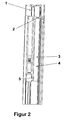
- a part of a frame profile 1 of a door frame is shown in a view and in section.
- the frame profile 1 consists in the present case of aluminum and is produced by extrusion. But it can also consist of steel, wood or a wood-plastic compound.
- a slide rail 2 is integrated, which is formed integrally with the frame profile 1 and cooperates with a arranged in a door leaf door closer.
- a slider 3 is guided, in addition, a buffer 4 is arranged in the slide rail 2, which serves as a stop limit.
- the frame profile 1 has at least within the slide rail 2 an anodized surface, which recommends itself as a friction partner for the slider 3 or provided as a force and motion transmission element of the door closer role.
- the slide rail 2 is provided with an opening 5, which is closed with a plug or cover 6 to the penetration to prevent contamination, insects, etc.
- the slide rail 2 also consist of a molded into the frame profile 1 plastic channel.
- a plurality of slide rails 2 may be integrated into the frame profile 1, which may each be equipped with different functional element.
- z. B. in an inner channel 2 a of the frame profile 1 the slider 3 are guided while in another slide, z. B. in a preferably made of plastic insulation web 2b of the frame profile 1, functional elements of a closing sequence control are housed.
- z. B. in an outer channel 2c of the frame profile 1 functional elements an opening limit, as the buffer 4 may be provided.
- a plurality of slide rails 2 are provided in the frame profile 1, all may be formed integrally with the frame profile 1. Alternatively, all may consist of molded into the frame profile 1 plastic channels. However, it is particularly advantageous if, in the case of a plurality of slide rails 2, at least one slide rail is formed integrally with the frame profile 1 and at least one slide rail consists of a plastic channel molded into the frame profile 1. As a result, a thermal separation between different frame parts can be realized in a simple manner.
- the invention described above can be used in both single-leaf and double-wing door systems.
Landscapes
- Engineering & Computer Science (AREA)
- Civil Engineering (AREA)
- Structural Engineering (AREA)
- Door And Window Frames Mounted To Openings (AREA)
- Wing Frames And Configurations (AREA)
Abstract
Description
- Die vorliegende Erfindung betrifft einen Türrahmen, bestehend aus einem Rahmenprofil, wobei in dem Türrahmen eine Gleitschiene für einen Türschließer angeordnet ist.
- Wenn bei einem aus einem Rahmenprofil bestehenden Türrahmen ein Türschließer verwendet werden soll, wird in aller Regel der Türschließer im Türblatt und die Gleitschiene im Türrahmen verbaut. Auch der umgekehrte Fall ist möglich, d. h. der Türschließer wird im Türrahmen und die Gleitschiene im Türblatt verbaut.
- Die Bereiche für den Türschließer und die Gleitschiene werden in der Regel vom Türenbauer frei gefräst, bevor diese mittels Befestigungszubehör im Türrahmen und im Türblatt montiert werden,
- Durch dieses Freifräsen wird jedoch der aus einem Rahmenprofil bestehende Türrahmen geschwächt. Dies führt zu einem Stabilitätsverlust der gesamten Türkonstruktion. Darüber hinaus ist das Ausfräsen der Aluprofile und Stege sowie das Befestigen mittels Befestigungszubehör aufwändig.
- Es ist daher Aufgabe der vorliegenden Erfindung, hier Abhilfe zu schaffen.
- Diese Aufgabe wird bei einem Türrahmen, bestehend aus einem Rahmenprofil, wobei in dem Türrahmen eine Gleitschiene für einen Türschließer angeordnet ist, erfindungsgemäß dadurch gelöst, dass die Gleitschiene integrierter Bestandteil des Rahmenprofils ist.
- Die erfindungsgemäße Lösung bietet den Vorteil, dass die Gleitschiene gleich bei der Herstellung des Rahmenprofils erzeugt wird. Dazu weist das Rahmenprofil einen Bereich auf, der später als Gleitschiene verwendet werden kann. Durch diese Maßnahme kann der Arbeitsgang des Ausfräsens entfallen, darüber hinaus wird das Rahmenprofil nicht durch die Ausfräsungen geschwächt und auch die aufwändige Befestigung der Gleitschiene entfällt, da diese bereist integrierter Bestandteil des Rahmenprofils ist.
- Die Unteransprüche haben vorteilhafte Weiterbildungen der Erfindung zum Inhalt.
- Gemäß einer bevorzugten Weiterbildung ist die Gleitschiene einstückig mit dem Rahmenprofils ausgebildet. Dies stellt eine besonders einfache und kostengünstige Integration der Gleitschiene in das Rahmenprofil dar.
- Das Rahmenprofil ist vorteilhafterweise mittels eines Extrusionsverfahrens hergestellt. Mithilfe dieses Verfahrens kann in besonders einfacher Weise eine einstückige Integration der Gleitschiene in das Rahmenprofils realisiert werden.
- Das Rahmenprofil weist gemäß einer bevorzugten Ausgestaltung zumindest innerhalb der Gleitschiene eine eloxierte Oberfläche auf. Eine eloxierte Oberfläche empfiehlt sich besonders als Reibpartner für ein in der Gleitschiene geführtes Gleitstück oder eine als Kraft- und Bewegungsübertragungselement des Türschließers vorgesehene Rolle.
- Um die Übertragungselemente, z. B. ein Gleitstück sowie Zubehör, wie Öffnungsbegrenzungspuffer, Feststellelemente usw. leicht und einfach in die Gleitschiene einbringen zu können, ist nach einer vorteilhaften Weiterbildung die Gleitschiene mit einer Öffnung versehen.
- Die Öffnung ist vorteilhafterweise mit einem Stopfen oder Deckel verschließbar, um das Eindringen von Verunreinigungen, Insekten usw. zu verhindern.
- Statt die Gleitschiene einstückig mit dem Rahmenprofil auszubilden, kann nach einer alternativen Ausgestaltung die Gleitschiene auch aus einem in das Rahmenprofil eingeformten Kunststoffkanal bestehen. Dieser Kunststoffkanal kann direkt bei der Herstellung oder auch nachträglich in das Rahmenprofil integriert werden.
- Nach einer weiteren vorteilhaften Ausgestaltung können auch mehrere Gleitschienen in das Rahmenprofil integriert sein, die jeweils mit unterschiedlichen Funktionselement bestückt sein können. Beispielsweise kann in einer Gleitschiene, z. B. in einem Innenkanal des Rahmenprofils, das Gleitstück geführt werden, während in einer anderen Gleitschiene, z. B. in einem Steg des Rahmenprofils, Funktionselemente einer Schließfolgeregelung untergebracht sind. In einer weiteren Gleitschiene, z. B. in einem Außenkanal des Rahmenprofils, können Funktionselemente einer Öffnungsbegrenzung vorgesehen sein.
- Wenn mehrere Gleitschienen in dem Rahmenprofil vorgesehen sind, können alle einstückig mit dem Rahmenprofil ausgebildet sein. Alternativ können auch alle aus in das Rahmenprofil eingeformten Kunststoffkanälen bestehen. Besonders vorteilhaft ist es jedoch, wenn bei mehreren Gleitschienen mindestens eine Gleitschiene einstückig mit dem Rahmenprofils ausgebildet ist und mindestens eine Gleitschiene aus einem in das Rahmenprofil eingeformten Kunststoffkanal besteht. Hierdurch kann auf einfache Weise eine thermische Trennung zwischen verschiedenen Rahmenteilen realisiert werden.
- Weitere Einzelheiten, Merkmale und Vorteile der Erfindung ergeben sich aus der nachfolgenden Beschreibung anhand der Zeichnungen. Es zeigen:
- Figur 1
- einen perspektivische Ansicht eines erfindungemäßen Türrahmens,
- Figur 2
- einen Schnitt durch den Türrahmen gemäß
Figur 1 , und - Figur 3
- einen Querschnitt durch den erfindungsgemäßen Türrahmen.
- In den Figuren ist ein Teil eines Rahmenprofils 1 eines Türrahmens in einer Ansicht und im Schnitt dargestellt.
- Das Rahmenprofil 1 besteht im vorliegenden Fall aus Aluminium und ist im Extrusionsverfahren hergestellt. Es kann aber auch aus Stahl, Holz oder einem Holz-Kunststoffcompound bestehen.
- In das Rahmenprofil 1 ist eine Gleitschiene 2 integriert, die einstückig mit dem Rahmenprofil 1 ausgebildet ist und mit einem in einem Türblatt angeordneten Türschließer zusammenwirkt.
- In der Gleitschiene 2 ist ein Gleitstück 3 geführt, außerdem ist in der Gleitschiene 2 ein Puffer 4 angeordnet, der als Anschlagsbegrenzung dient. Das Rahmenprofil 1 weist zumindest innerhalb der Gleitschiene 2 eine eloxierte Oberfläche auf, die sich besonders als Reibpartner für das Gleitstück 3 oder eine als Kraft- und Bewegungsübertragungselement des Türschließers vorgesehene Rolle empfiehlt.
- Um die Übertragungselemente, z. B. das Gleitstück 3 sowie Zubehör, wie den Puffer 4, Feststellelemente usw. leicht und einfach in die Glekschiene 2 einbringen zu können, ist die Gleitschiene 2 mit einer Öffnung 5 versehen, weiche mit einem Stopfen oder Deckel 6 verschließbar ist, um das Eindringen von Verunreinigungen, Insekten usw. zu verhindern.
- Alternativ kann die Gleitschiene 2 auch aus einem in das Rahmenprofil 1 eingeformten Kunststoffkanal bestehen. Darüber hinaus können auch mehrere Gleitschienen 2 in das Rahmenprofil 1 integriert sein, die jeweils mit unterschiedlichen Funktionselement bestückt sein können. Beispielsweise kann in einer Gleitschiene, z. B. in einem Innenkanal 2a des Rahmenprofils 1, das Gleitstück 3 geführt werden, während in einer anderen Gleitschiene, z. B. in einem vorzugsweise aus Kunststoff gefertigten Isolationssteg 2b des Rahmenprofils 1, Funktionselemente einer Schließfolgeregelung untergebracht sind. In einer weiteren Gleitschiene, z. B. in einem Außenkanal 2c des Rahmenprofils 1, können Funktionselemente einer Öffnungsbegrenzung, wie der Puffer 4 vorgesehen sein.
- Wenn mehrere Gleitschienen 2 in dem Rahmenprofil 1 vorgesehen sind, können alle einstückig mit dem Rahmenprofil 1 ausgebildet sein. Alternativ können auch alle aus in das Rahmenprofil 1 eingeformten Kunststoffkanälen bestehen. Besonders vorteilhaft ist es jedoch, wenn bei mehreren Gleitschienen 2 mindestens eine Gleitschiene einstückig mit dem Rahmenprofils 1 ausgebildet ist und mindestens eine Gleitschiene aus einem in das Rahmenprofil 1 eingeformten Kunststoffkanal besteht. Hierdurch kann auf einfache Weise eine thermische Trennung zwischen verschiedenen Rahmenteilen realisiert werden.
- Die vorstehend beschriebene Erfindung kann sowohl bei einflügeligen als auch bei doppelflügellgen Türsystemen verwendet werden.
- Die vorhergehende Beschreibung der vorliegenden Erfindung dient nur zu illustrativen Zwecken und nicht zum Zwecke der Beschränkung der Erfindung. Im Rahmen der Erfindung sind verschiedene Änderungen und Modifikationen möglich, ohne den Umfang der Erfindung sowie ihrer Äquivalente zu verlassen.
-
- 1
- Rahmenprofil
- 2
- Gleitschiene
- 2a
- Innenkanal
- 2b
- Isolationssteg
- 2c
- Außenkanal
- 3
- Gleitstück
- 4
- Puffer
- 5
- Öffnung
- 6
- Stopfen oder Deckel
Claims (9)
- Türrahmen, bestehend aus einem Rahmenprofil, wobei in dem Türrahmen eine Gleitschiene für einen Türschließer angeordnet ist, dadurch gekennzeichnet, dass die Gleitschiene (2) integrierter Bestandteil des Rahmenprofils (1) ist.
- Türrahmen nach Anspruch 1, dadurch gekennzeichnet, dass die Gleitschiene (2) einstückig mit dem Rahmenprofils (1) ausgebildet ist.
- Türrahmen nach Anspruch 1 oder 2, dadurch gekennzeichnet, dass das Rahmenprofil (1) mittels eines Extrusionsverfahrens hergestellt ist.
- Türrahmen nach einem der Ansprüche 1 bis 3, dadurch gekennzeichnet, dass das Rahmenprofil (1) zumindest innerhalb der Gleitschiene (2) eine eloxierte Oberfläche aufweist.
- Türrahmen nach einem der Ansprüche 1 bis 3, dadurch gekennzeichnet, dass die Gleitschiene (2) mit einer Öffnung (5) versehen ist, um Übertragungselemente, Zubehör usw. in die Gleitschiene (2) einzubringen.
- Türrahmen nach Anspruch 5, dadurch gekennzeichnet, dass die Öffnung (6) mit einem Stopfen oder Deckel (6) verschließbar ist.
- Türrahmen nach Anspruch 1, dadurch gekennzeichnet, dass die Gleitschiene (2) aus einem in das Rahmenprofil (1) eingeformten Kunststoffkanal besteht.
- Türrahmen nach einem der Ansprüche 1 bis 7, dadurch gekennzeichnet, dass mehrere Gleitschienen (2) in dem Rahmenprofil (1) vorgesehen sind.
- Türrahmen nach Anspruch 8, dadurch gekennzeichnet, dass bei mehreren Gleitschienen (2) mindestens eine Gleitschiene einstückig mit dem Rahmenprofils (1) ausgebildet ist und mindestens eine Gleitschiene aus einem in das Rahmenprofil (1) eingeformten Kunststoffkanal besteht.
Applications Claiming Priority (1)
| Application Number | Priority Date | Filing Date | Title |
|---|---|---|---|
| DE201110050854 DE102011050854A1 (de) | 2011-06-06 | 2011-06-06 | Türrahmen |
Publications (1)
| Publication Number | Publication Date |
|---|---|
| EP2532819A1 true EP2532819A1 (de) | 2012-12-12 |
Family
ID=46045656
Family Applications (1)
| Application Number | Title | Priority Date | Filing Date |
|---|---|---|---|
| EP12002729A Withdrawn EP2532819A1 (de) | 2011-06-06 | 2012-04-19 | Türrahmen |
Country Status (2)
| Country | Link |
|---|---|
| EP (1) | EP2532819A1 (de) |
| DE (1) | DE102011050854A1 (de) |
Cited By (1)
| Publication number | Priority date | Publication date | Assignee | Title |
|---|---|---|---|---|
| FR3020086A1 (fr) * | 2014-04-18 | 2015-10-23 | Somfy Sas | Installation de volet battant |
Citations (5)
| Publication number | Priority date | Publication date | Assignee | Title |
|---|---|---|---|---|
| DE20014920U1 (de) * | 2000-08-29 | 2000-10-19 | Hettich-Heinze GmbH & Co. KG, 32139 Spenge | Schiebetürführung |
| DE10064952A1 (de) * | 2000-12-23 | 2002-06-27 | Geze Gmbh | Tür, vorzugsweise Brandschutztür, mit einer Antriebseinrichtung |
| DE29522429U1 (de) * | 1995-02-07 | 2003-09-11 | Dorma Gmbh + Co. Kg, 58256 Ennepetal | Brand- bzw. Feuerschutztür |
| EP1437478A2 (de) * | 2003-01-10 | 2004-07-14 | SCHÜCO International KG | Wärmegedämmtes Verbundprofil |
| DE102008012555A1 (de) * | 2008-03-04 | 2009-09-10 | Eco Schulte Gmbh & Co. Kg | Kunststoffgleitschiene mit Verstärkungselement |
-
2011
- 2011-06-06 DE DE201110050854 patent/DE102011050854A1/de not_active Withdrawn
-
2012
- 2012-04-19 EP EP12002729A patent/EP2532819A1/de not_active Withdrawn
Patent Citations (5)
| Publication number | Priority date | Publication date | Assignee | Title |
|---|---|---|---|---|
| DE29522429U1 (de) * | 1995-02-07 | 2003-09-11 | Dorma Gmbh + Co. Kg, 58256 Ennepetal | Brand- bzw. Feuerschutztür |
| DE20014920U1 (de) * | 2000-08-29 | 2000-10-19 | Hettich-Heinze GmbH & Co. KG, 32139 Spenge | Schiebetürführung |
| DE10064952A1 (de) * | 2000-12-23 | 2002-06-27 | Geze Gmbh | Tür, vorzugsweise Brandschutztür, mit einer Antriebseinrichtung |
| EP1437478A2 (de) * | 2003-01-10 | 2004-07-14 | SCHÜCO International KG | Wärmegedämmtes Verbundprofil |
| DE102008012555A1 (de) * | 2008-03-04 | 2009-09-10 | Eco Schulte Gmbh & Co. Kg | Kunststoffgleitschiene mit Verstärkungselement |
Cited By (1)
| Publication number | Priority date | Publication date | Assignee | Title |
|---|---|---|---|---|
| FR3020086A1 (fr) * | 2014-04-18 | 2015-10-23 | Somfy Sas | Installation de volet battant |
Also Published As
| Publication number | Publication date |
|---|---|
| DE102011050854A1 (de) | 2012-12-06 |
Similar Documents
| Publication | Publication Date | Title |
|---|---|---|
| EP2631414B1 (de) | Führungsschiene für Senkrechtmarkise und Senkrechtmarkise | |
| DE202009003392U1 (de) | Mehrteiliges Schwellenprofil für eine Hebeschiebetür | |
| EP3112577B1 (de) | Absenkdichtung | |
| DE202016102808U1 (de) | Möbel mit einem an einem Laufprofil verfahrbaren Schiebeelement und einer Führungseinrichtung | |
| DE102016216835B4 (de) | Aushebesicherung für einen verschiebbaren und zum Verschieben anhebbaren Flügel | |
| EP3978714A1 (de) | Ortsveränderbares torblatt sowie sektionsabschlusselement eines torblattes | |
| DE102011050854A1 (de) | Türrahmen | |
| DE102014224811B3 (de) | Glasschiebetür für eine Duschkabine | |
| EP2369115A2 (de) | Aushebesicherung für Schiebefenster oder Schiebetüren | |
| EP2354431A2 (de) | Rollladenkasten mit Lamellenführungsteilen | |
| CH702394B1 (de) | Schiebewand mit wenigstens zwei Flügeln. | |
| EP3715576B1 (de) | Universeller schwellenverbinder mit wechselelement | |
| DE202012004988U1 (de) | Bauelement | |
| EP2072744B1 (de) | Zargenprofil für eine Hebe-Schiebetür | |
| DE102011010773A1 (de) | Rahmenkonstruktion für ein Fenster oder eine Tür | |
| EP3282079B1 (de) | Absenkdichtungseinheit für eine schwellenlose tür | |
| WO2005088053A1 (de) | Kassette zur kraftübertragung in einem fensterheber | |
| EP3770362B1 (de) | Vorrichtung zum verschliessen von gebäudeöffnungen mit schiebewänden und entsprechendes herstellungsverfahren | |
| EP3196395B1 (de) | Tür mit einem griffprofil | |
| EP2532822A2 (de) | Türrahmen | |
| DE20300786U1 (de) | Seitenlauftor | |
| DE102009049951B4 (de) | Führungsschiene für einen Seilzug-Fensterheber eines Kraftfahrzeuges sowie Fensterheber | |
| EP3156578B1 (de) | Sektionaltor | |
| EP3199733A1 (de) | Vorrichtung zum verschliessen von gebäudeöffnungen | |
| DE1979530U (de) | Zentralverschluss, insbesondere fuer schwingfluegel- und wendefluegelfenster. |
Legal Events
| Date | Code | Title | Description |
|---|---|---|---|
| PUAI | Public reference made under article 153(3) epc to a published international application that has entered the european phase |
Free format text: ORIGINAL CODE: 0009012 |
|
| AK | Designated contracting states |
Kind code of ref document: A1 Designated state(s): AL AT BE BG CH CY CZ DE DK EE ES FI FR GB GR HR HU IE IS IT LI LT LU LV MC MK MT NL NO PL PT RO RS SE SI SK SM TR |
|
| AX | Request for extension of the european patent |
Extension state: BA ME |
|
| 17P | Request for examination filed |
Effective date: 20130612 |
|
| RBV | Designated contracting states (corrected) |
Designated state(s): AL AT BE BG CH CY CZ DE DK EE ES FI FR GB GR HR HU IE IS IT LI LT LU LV MC MK MT NL NO PL PT RO RS SE SI SK SM TR |
|
| RAP1 | Party data changed (applicant data changed or rights of an application transferred) |
Owner name: DORMA DEUTSCHLAND GMBH |
|
| 17Q | First examination report despatched |
Effective date: 20160224 |
|
| STAA | Information on the status of an ep patent application or granted ep patent |
Free format text: STATUS: THE APPLICATION IS DEEMED TO BE WITHDRAWN |
|
| 18D | Application deemed to be withdrawn |
Effective date: 20160706 |