EP2532813A1 - Gear rack - Google Patents
Gear rack Download PDFInfo
- Publication number
- EP2532813A1 EP2532813A1 EP11169100A EP11169100A EP2532813A1 EP 2532813 A1 EP2532813 A1 EP 2532813A1 EP 11169100 A EP11169100 A EP 11169100A EP 11169100 A EP11169100 A EP 11169100A EP 2532813 A1 EP2532813 A1 EP 2532813A1
- Authority
- EP
- European Patent Office
- Prior art keywords
- rack
- coupling means
- drive
- drive rod
- recess
- Prior art date
- Legal status (The legal status is an assumption and is not a legal conclusion. Google has not performed a legal analysis and makes no representation as to the accuracy of the status listed.)
- Granted
Links
Images

Classifications
-
- E—FIXED CONSTRUCTIONS
- E05—LOCKS; KEYS; WINDOW OR DOOR FITTINGS; SAFES
- E05B—LOCKS; ACCESSORIES THEREFOR; HANDCUFFS
- E05B63/00—Locks or fastenings with special structural characteristics
- E05B63/0056—Locks with adjustable or exchangeable lock parts
-
- E—FIXED CONSTRUCTIONS
- E05—LOCKS; KEYS; WINDOW OR DOOR FITTINGS; SAFES
- E05C—BOLTS OR FASTENING DEVICES FOR WINGS, SPECIALLY FOR DOORS OR WINDOWS
- E05C9/00—Arrangements of simultaneously actuated bolts or other securing devices at well-separated positions on the same wing
- E05C9/02—Arrangements of simultaneously actuated bolts or other securing devices at well-separated positions on the same wing with one sliding bar for fastening when moved in one direction and unfastening when moved in opposite direction; with two sliding bars moved in the same direction when fastening or unfastening
- E05C9/021—Arrangements of simultaneously actuated bolts or other securing devices at well-separated positions on the same wing with one sliding bar for fastening when moved in one direction and unfastening when moved in opposite direction; with two sliding bars moved in the same direction when fastening or unfastening with rack and pinion mechanism
Definitions
- the invention relates to a rack for a drive rod fitting which has at least on its upper side a plurality of drive recesses for engagement of a drive pinion.
- a drive rod of the espagnolette fitting is displaced by a drive pinion, which engages in drive recesses of the drive rod.
- the drive pinion is rotated via a mandrel, which is connected, for example, with an actuating element, such as a handle.
- the measure between the pivot point of the drive pinion and the underside of the drive rod is referred to as a backset.
- the backset is typically between 11 mm and 15 mm. The backset is so far specified for each espagnolette fitting. If a different backset on one wing is desired, then another can not be another Drive pinion can be used with a different diameter.
- the invention is therefore based on the object to provide a device with which different backset dimensions can be realized when using the same drive rod and the same drive pinion.
- a rack for a drive rod fitting having at least on its upper side a plurality of drive recesses for engagement of a drive pinion, wherein the rack at its top side opposite the underside at least a first coupling means for coupling the rack with a drive rod of the espagnolette or a has another rack.
- the toothed rack can be arranged on the drive rod by the first coupling means.
- the drive pinion then no longer engages in the drive recesses of the drive rod but in the drive recesses of the rack. If a smaller backset is desired, the rack between the drive pinion and the drive rod can be removed again.
- the rack on its upper side at least a second coupling means for coupling with another rack on the top of the rack.
- a second coupling means for coupling with another rack on the top of the rack.
- the first and / or second coupling means may be formed as a recess or projection.
- Recesses and projections can be particularly simple and inexpensive, e.g. by embossing, are made.
- At least one projection and / or at least one recess preferably have a round cross-section. Round projections and recesses can be made very easy. Furthermore, by avoiding sharp edges, the risk of injury to the user when handling the rack decreases.
- the first coupling means and the second coupling means are coordinated.
- the first coupling means and the second coupling means are preferably arranged opposite one another.
- the individual racks can thereby be arranged in any order to each other.
- coupling means in the form of recesses and projections are used, they are preferably arranged such that at least one recess provided on the upper side, or at least one projection provided on the upper side with a projection provided on the underside of the rack, or one on the underside of the rack provided recess, aligned.
- the rack is preferably via the first and / or second coupling means positively and / or non-positively connected to a further rack.
- the racks can be arranged so free of play to each other.
- the arranged on the drive rod rack is arranged without play on the drive rod. An actuation of the actuating element and thus of the drive pinion can be transmitted directly to the locking elements.
- the rack preferably has two first and second coupling means. By the two “coupling means pairs" several racks can be arranged rotationally fixed to each other.
- the first and second coupling means may be provided in the region of the longitudinal ends of the rack.
- racks are so particularly rotatable to each other can be arranged.
- end-side arrangement of the coupling means remains space for the drive recesses in the central region of the rack.
- the coupling means may be provided symmetrically to the central, perpendicular to the top of the rack extending symmetry axis.
- the coupling means may be provided symmetrically to this axis of symmetry.
- the rack can be rotated about this axis of symmetry, without changing the arrangement possibility of the other rack (s) or the drive rod, changed. Therefore, when the rack is arranged, the user does not need to pay any attention to the orientation of the rack around this axis of symmetry.
- the rack may extend both along a first longitudinal direction Driving rod as well as rotated by 180 ° to be arranged. The arrangement of the rack is thereby particularly simple.
- the top and bottom of the rack are preferably flat except for the coupling means and the drive recesses. As a result, several racks can be stacked form-fitting.
- the rack is integrally formed. This results in particularly low production costs for the rack.
- the invention further relates to a method for producing a previously described rack, in which at least one recess is embossed in an upper side or underside of the rack such that a projection aligned with the recess is formed on the opposite upper side or lower side.
- Recess and projection can be produced with a single manufacturing step.
- all recesses or recesses and drive recesses of the rack are produced in a single manufacturing step.
- the rack is so particularly inexpensive to produce.
- the invention further relates to a drive rod fitting, with a provided with at least one rack coupling means drive rod and at least one rack previously described.
- the drive rod of the espagnolette preferably has two rack coupling means for coupling to a rack.
- the rack in particular play, be connected to the drive rod.
- the drive rod may have at its, the rack-facing top, drive recesses to be used without a rack can.
- At least two racks are provided, each with different heights.
- the height of a single rack is preferably chosen smaller than 3 mm. The user can thus realize in a simple manner by means of a combination of one or more racks a desired backset.
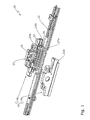
- FIG. 1 illustrates an espagnolette 10 according to the invention for actuating locking elements of a door leaf (not shown).
- the espagnolette fitting 10 has a drive rod 12 and a Drive housing 14 on.
- the drive housing 14 comprises two drive housing shells 14a, 14b.
- the drive housing shells 14a, 14b respectively have guide projections 16a, 16b which engage behind the drive rod 12 in order to guide the drive rod 12 in the drive housing 14.
- the espagnolette fitting 10 furthermore has a drive pinion 18.
- the drive pinion 18 is guided in recesses, not shown, of the drive housing shells 14a, 14b.
- the drive pinion 18 has a substantially square edged mandrel recess 20 for a with a actuator (not shown) coupled in cross-section rectangular mandrel.
- the mandrel recess 20 represents the axis of rotation of the drive pinion 18.
- An actuation of the actuating element coupled to a mandrel therefore leads to a rotation of the drive
- the rotation of the drive pinion 18 leads to a displacement of a first rack 22 according to the invention.
- the first rack 22 has a plurality of drive recesses, of which, for reasons of clarity, only a first drive recess 24a is provided with a reference numeral.
- the drive pinion 18 has a plurality of unspecified teeth for displacement of the first rack 22, which engage in the drive recesses of the first rack 22.
- a movement of the first rack 22 is transmitted to a second rack 26, which is identical to the first rack 22 formed. From the second rack 26, the movement is further transmitted to the drive rod 12.
- the drive rod 12 itself has drive recesses, of which, for reasons of clarity, only a first drive recess 27a is provided with a reference numeral.
- the drive pinion 18 could therefore, when using a corresponding housing, engage directly in the drive recesses of the drive rod 12.
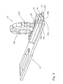
- FIG. 2 shows the drive pinion 18 with drive pinion projections 28a, 28b, which engage in corresponding recesses of the FIG. 2
- Drive housing shells not shown can be used.
- the first rack 22 is shown partially cut.
- a first coupling means 30a designed in the form of a round projection can be seen.
- the first coupling means 30 a is formed on the underside 32 of the first rack 22.
- a second coupling means 36a is formed in the form of a round recess or depression.
- the first coupling means 30a has the shape of a protrusion with a round diameter.
- the first coupling means 30a is inserted in a second coupling means 38a of the second rack 26.
- a first coupling means 40a of the second rack 26 is in turn inserted into a first rack coupling means 42a of the drive rod 12.
- the coupling means 30a, 40a designed as projections here are aligned with the coupling means 36a, 38a, 42a which are designed as recesses.
- the diameters of the coupling means 30a, 36a, 38a, 40a, 42a are further adapted to each other such that an interference fit between the first rack 22, the second rack 26 and the drive rod 12 is formed.
- the first rack 22 can thereby be attached to the second rack 26.
- the second rack 26 can be plugged onto the drive rod 12. A tool for fixed arrangement of the first rack 22 on the second rack 26 and this on the drive rod 12 is therefore not needed.
- the first rack 22 and the second rack 26 can be removed without tools from the
- FIG. 3 shows a second drive rod fitting 10 'according to the invention with a drive pinion 18', whose movement is transmitted to a drive rod 12 '.
- a drive pinion 18' To move the drive pinion 18 ', this is rotated about an axis of rotation 44 by means of an actuating element, not shown.
- the first rack 22 ' has first coupling means 30a', 30b and second coupling means 36a ', 36b.
- the first coupling means 30a ', 30b are formed as projections with a round cross-section.
- the second coupling means 36a ', 36b are formed as recesses with a round cross-section.
- the first coupling means 30a ', 30b are provided symmetrically to a central axis of symmetry 46 extending perpendicularly to an upper side 34' of the first rack 22 '.
- the second coupling means 36a ', 36b are formed symmetrically to the axis 46.
- the first rack 22 'can thus also, as indicated by an arrow 48, are used rotated by 180 °.
- the first rack 22 ' has a plurality of drive recesses, of which, for reasons of clarity, only a first drive recess 24a' is provided with a reference numeral.
- the upper side 34 ' is flat except for the drive recesses and the second coupling means 36a', 36b.
- a bottom 32 'of the first rack 22' is flat except for the first coupling means 30a ', 30b.
- the second rack 26 ' is identical to the first rack 22' is formed. Due to the essentially flat training of the first Rack 22 'and the second rack 26' they can be easily stacked one above the other. Furthermore, the second rack 26 'can be easily placed on the drive rod 12'.
- the coupling means 30a ', 30b, 36a', 36b are coordinated so that a plurality of racks 22 ', 26' can be positively inserted into one another.
- the distance between the pivot point 44 of the drive pinion 18 'and a bottom 50 of the drive rod 12' is referred to as a backset in the context of the invention.
- the backset according to the arrangement of the espagnolette 10 'is designated by a first dimension 52. If the espagnolette fitting 10 'is now inserted on another wing (not shown) having a smaller backset, the first rack 22' and / or the second rack 26 'can be removed from the espagnolette fitting 10'.
- the drive pinion 18 'can now be arranged closer to the drive rod 12', resulting in a smaller backset.
- the at a removal of the first rack 22 'and the second rack 26' resulting backset is in Fig. 3 represented by a second dimension 54.
Landscapes
- Engineering & Computer Science (AREA)
- Structural Engineering (AREA)
- Mechanical Engineering (AREA)
- Transmission Devices (AREA)
- Labeling Devices (AREA)
Abstract
Description
Die Erfindung betrifft eine Zahnstange für einen Treibstangenbeschlag die zumindest an ihrer Oberseite mehrere Antriebsvertiefungen zum Eingriff eines Antriebsritzels aufweist.The invention relates to a rack for a drive rod fitting which has at least on its upper side a plurality of drive recesses for engagement of a drive pinion.
Es ist bekannt, einen Fenster- oder Türflügel mit einem Treibstangenbeschlag zur Steuerung von Verriegelungselementen des Flügels zu versehen. Eine Treibstange des Treibstangenbeschlags wird dabei durch ein Antriebsritzel verschoben, das in Antriebsvertiefungen der Treibstange eingreift. Das Antriebsritzel wird über einen Dorn gedreht, der beispielsweise mit einem Betätigungselement, wie einem Griff, verbunden ist. Das Maß zwischen dem Drehpunkt des Antriebsritzels und der Unterseite der Treibstange wird als Dornmaß bezeichnet. Das Dornmaß beträgt typischerweise zwischen 11 mm und 15 mm. Das Dornmaß ist bislang für jeden Treibstangenbeschlag genau festgelegt. Wird ein anderes Dornmaß an einem Flügel gewünscht, so kann nicht einfach ein anderes Antriebsritzel mit einem anderen Durchmesser verwendet werden. Bei Verwendung eines anderen Antriebsritzel würde nämlich der Treibstangenbeschlag bei Betätigung des Betätigungselements einen anderen Weg zurücklegen. Die Verriegelungselemente würden dann nicht mehr in derselben Position des Betätigungselements verriegeln, wie bei Verwendung des ursprünglichen Antriebsritzels. Eine Vorrichtung, mit der unterschiedliche Dornmaß bei Verwendung des gleichen Antriebsritzels realisiert werden können, ist bislang nicht bekannt.It is known to provide a window or door leaf with a drive rod fitting for controlling locking elements of the wing. A drive rod of the espagnolette fitting is displaced by a drive pinion, which engages in drive recesses of the drive rod. The drive pinion is rotated via a mandrel, which is connected, for example, with an actuating element, such as a handle. The measure between the pivot point of the drive pinion and the underside of the drive rod is referred to as a backset. The backset is typically between 11 mm and 15 mm. The backset is so far specified for each espagnolette fitting. If a different backset on one wing is desired, then another can not be another Drive pinion can be used with a different diameter. When using a different drive pinion namely the drive rod fitting would cover a different way when operating the actuator. The locking elements would then no longer lock in the same position of the actuating element as when using the original drive pinion. A device with which different backset can be realized using the same drive pinion is not yet known.
Der Erfindung liegt daher die Aufgabe zugrunde, eine Vorrichtung bereit zu stellen, mit der bei Verwendung der gleichen Treibstange und des gleichen Antriebsritzels verschiedene Dornmaße realisiert werden können.The invention is therefore based on the object to provide a device with which different backset dimensions can be realized when using the same drive rod and the same drive pinion.
Diese Aufgabe wird erfindungsgemäß durch eine Zahnstange für einen Treibstangenbeschlag, die zumindest an ihrer Oberseite mehrere Antriebsvertiefungen zum Eingriff eines Antriebsritzels aufweist, gelöst, wobei die Zahnstange an ihrer der Oberseite gegenüberliegenden Unterseite zumindest ein erstes Kupplungsmittel zur Kopplung der Zahnstange mit einer Treibstange des Treibstangenbeschlags oder einer weiteren Zahnstange aufweist.This object is achieved by a rack for a drive rod fitting having at least on its upper side a plurality of drive recesses for engagement of a drive pinion, wherein the rack at its top side opposite the underside at least a first coupling means for coupling the rack with a drive rod of the espagnolette or a has another rack.
Wird für den Treibstangenbeschlag ein größeres Dornmaß als bislang vorgesehen gewünscht, so kann die Zahnstange durch das erste Kupplungsmittel an der Treibstange angeordnet werden. Das Antriebsritzel greift dann nicht mehr in die Antriebsvertiefungen der Treibstange sondern in die Antriebsvertiefungen der Zahnstange ein. Wird ein kleineres Dornmaß gewünscht, so kann die Zahnstange zwischen dem Antriebsritzel und der Treibstange wieder entnommen werden.If a larger backset than previously provided is desired for the espagnolette fitting, then the toothed rack can be arranged on the drive rod by the first coupling means. The drive pinion then no longer engages in the drive recesses of the drive rod but in the drive recesses of the rack. If a smaller backset is desired, the rack between the drive pinion and the drive rod can be removed again.
In bevorzugter Ausgestaltung der Erfindung weist die Zahnstange an ihrer Oberseite zumindest ein zweites Kopplungsmittel zur Kopplung mit einer weiteren Zahnstange an der Oberseite der Zahnstange auf. Zusätzlich zu der ersten Zahnstange können so weitere Zahnstangen zwischen das Antriebsritzel und die Treibstange eingebracht werden, um noch größere Dornmaße realisieren zu können.In a preferred embodiment of the invention, the rack on its upper side at least a second coupling means for coupling with another rack on the top of the rack. In addition to the first rack so more racks between the drive pinion and the drive rod can be introduced to realize even larger backstroke can.
Das erste und/oder zweite Kopplungsmittel können als Ausnehmung oder Vorsprung ausgebildet sein. Ausnehmungen und Vorsprünge können dabei besonders einfach und kostengünstig, z.B. durch Prägen, gefertigt werden.The first and / or second coupling means may be formed as a recess or projection. Recesses and projections can be particularly simple and inexpensive, e.g. by embossing, are made.
Zumindest ein Vorsprung und/oder zumindest eine Ausnehmung weisen vorzugsweise einen runden Querschnitt auf. Runde Vorsprünge und Ausnehmungen können dabei besonders einfach gefertigt werden. Ferner sinkt durch die Vermeidung scharfer Kanten die Verletzungsgefahr des Benutzers beim Hantieren der Zahnstange.At least one projection and / or at least one recess preferably have a round cross-section. Round projections and recesses can be made very easy. Furthermore, by avoiding sharp edges, the risk of injury to the user when handling the rack decreases.
In bevorzugter Ausgestaltung der Erfindung sind das erste Kupplungsmittel und das zweite Kopplungsmittel aufeinander abgestimmt. Das erste Kopplungsmittel und das zweite Kupplungsmittel sind dabei vorzugsweise einander gegenüberliegend angeordnet. Bei der Verwendung mehrerer Zahnstangen zur Realisierung eines großen Dornmaßes können die einzelnen Zahnstangen dadurch in beliebiger Reihenfolge zueinander angeordnet werden. Werden Kopplungsmittel in Form von Ausnehmungen und Vorsprüngen eingesetzt, werden diese vorzugsweise so angeordnet, dass zumindest eine auf der Oberseite vorgesehene Ausnehmung, oder zumindest ein auf der Oberseite vorgesehener Vorsprung mit einem auf der Unterseite der Zahnstange vorgesehenen Vorsprung, oder einer auf der Unterseite der Zahnstange vorgesehenen Ausnehmung, fluchtet.In a preferred embodiment of the invention, the first coupling means and the second coupling means are coordinated. The first coupling means and the second coupling means are preferably arranged opposite one another. When using multiple racks to realize a large backset the individual racks can thereby be arranged in any order to each other. If coupling means in the form of recesses and projections are used, they are preferably arranged such that at least one recess provided on the upper side, or at least one projection provided on the upper side with a projection provided on the underside of the rack, or one on the underside of the rack provided recess, aligned.
Die Zahnstange ist vorzugsweise über das erste und/oder zweite Kupplungsmittel form- und/oder kraftschlüssig mit einer weiteren Zahnstange verbindbar. Die Zahnstangen können so spielfrei zueinander angeordnet werden. Vorzugsweise ist auch die an der Treibstange angeordnete Zahnstange spielfrei an der Treibstange angeordnet. Eine Betätigung des Betätigungselements und somit des Antriebsritzels kann dadurch direkt auf die Verriegelungselemente übertragen werden.The rack is preferably via the first and / or second coupling means positively and / or non-positively connected to a further rack. The racks can be arranged so free of play to each other. Preferably, the arranged on the drive rod rack is arranged without play on the drive rod. An actuation of the actuating element and thus of the drive pinion can be transmitted directly to the locking elements.
Die Zahnstange weist vorzugsweise zwei erste und zweite Kopplungsmittel auf. Durch die beiden "Kopplungsmittel-Paare" können mehrere Zahnstangen drehfest zueinander angeordnet werden.The rack preferably has two first and second coupling means. By the two "coupling means pairs" several racks can be arranged rotationally fixed to each other.
Die ersten und zweiten Kupplungsmittel können im Bereich der längsseitigen Enden der Zahnstange vorgesehen sein. Mehrere Zahnstangen sind so besonders drehfest zueinander anordenbar. Weiterhin bleibt durch die endseitige Anordnung der Kopplungsmittel Platz für die Antriebsvertiefungen im mittleren Bereich der Zahnstange.The first and second coupling means may be provided in the region of the longitudinal ends of the rack. Several racks are so particularly rotatable to each other can be arranged. Furthermore, by the end-side arrangement of the coupling means remains space for the drive recesses in the central region of the rack.
Die Kopplungsmittel können symmetrisch zur mittigen, senkrecht zur Oberseite der Zahnstange verlaufenden Symmetrieachse vorgesehen sein. Durch die Mitte der Zahnstange kann dabei eine Symmetrieachse gedacht werden, die senkrecht auf der Oberseite der Zahnstange steht. Die Kopplungsmittel können symmetrisch zu dieser Symmetrieachse vorgesehen sein. In diesem Fall kann die Zahnstange um diese Symmetrieachse gedreht werden, ohne dass sich die Anordnungsmöglichkeit der anderen Zahnstange(n) oder der Treibstange, verändert. Um diese Symmetrieachse muss der Benutzer bei Anordnung der Zahnstange daher keine Orientierung der Zahnstange beachten: Die Zahnstange kann sowohl in eine erste Längsrichtung entlang der Treibstange als auch um 180° verdreht dazu angeordnet werden. Die Anordnung der Zahnstange wird dadurch besonders einfach.The coupling means may be provided symmetrically to the central, perpendicular to the top of the rack extending symmetry axis. By the center of the rack while an axis of symmetry can be thought, which is perpendicular to the top of the rack. The coupling means may be provided symmetrically to this axis of symmetry. In this case, the rack can be rotated about this axis of symmetry, without changing the arrangement possibility of the other rack (s) or the drive rod, changed. Therefore, when the rack is arranged, the user does not need to pay any attention to the orientation of the rack around this axis of symmetry. The rack may extend both along a first longitudinal direction Driving rod as well as rotated by 180 ° to be arranged. The arrangement of the rack is thereby particularly simple.
Die Oberseite und Unterseite der Zahnstange sind vorzugsweise bis auf die Kupplungsmittel und die Antriebsvertiefungen eben ausgebildet. Hierdurch können mehrere Zahnstangen formschlüssig gestapelt werden.The top and bottom of the rack are preferably flat except for the coupling means and the drive recesses. As a result, several racks can be stacked form-fitting.
In bevorzugter Ausgestaltung der Erfindung ist die Zahnstange einteilig ausgebildet. Hierdurch ergeben sich besonders niedrige Fertigungskosten für die Zahnstange.In a preferred embodiment of the invention, the rack is integrally formed. This results in particularly low production costs for the rack.
Die Erfindung betrifft weiterhin ein Verfahren zur Herstellung einer zuvor beschriebenen Zahnstange, bei dem zumindest eine Ausnehmung derart in eine Oberseite oder Unterseite der Zahnstange geprägt wird, dass ein mit der Ausnehmung fluchtender Vorsprung an der gegenüberliegenden Oberseite oder Unterseite ausgeprägt wird. Ausnehmung und Vorsprung können so mit einem einzigen Fertigungsschritt hergestellt werden. Vorzugsweise werden alle Ausnehmungen bzw. Vertiefungen sowie Antriebsvertiefungen der Zahnstange in einem einzigen Fertigungsschritt hergestellt. Die Zahnstange ist so besonders kostengünstig herstellbar.The invention further relates to a method for producing a previously described rack, in which at least one recess is embossed in an upper side or underside of the rack such that a projection aligned with the recess is formed on the opposite upper side or lower side. Recess and projection can be produced with a single manufacturing step. Preferably, all recesses or recesses and drive recesses of the rack are produced in a single manufacturing step. The rack is so particularly inexpensive to produce.
Die Erfindung betrifft weiterhin einen Treibstangenbeschlag, mit einer mit zumindest einem Zahnstangenkopplungsmittel versehenen Treibstange und zumindest einer zuvor beschriebenen Zahnstange.The invention further relates to a drive rod fitting, with a provided with at least one rack coupling means drive rod and at least one rack previously described.
Die Treibstange des Treibstangenbeschlags weist vorzugsweise zwei Zahnstangenkopplungsmittel zur Kopplung mit einer Zahnstange auf. Durch die Zahnstangenkopplungsmittel kann die Zahnstange, insbesondere spielfrei, mit der Treibstange verbunden werden.The drive rod of the espagnolette preferably has two rack coupling means for coupling to a rack. By the rack coupling means, the rack, in particular play, be connected to the drive rod.
Die Treibstange kann an ihrer, der Zahnstange zugewandten Oberseite, Antriebsvertiefungen aufweisen, um ohne Zahnstange eingesetzt werden zu können.The drive rod may have at its, the rack-facing top, drive recesses to be used without a rack can.
In bevorzugter Ausgestaltung der Erfindung sind zumindest zwei Zahnstangen mit jeweils unterschiedlichen Höhen vorgesehen. Die Höhe einer einzelnen Zahnstange ist vorzugsweise kleiner als 3 mm gewählt. Der Benutzer kann so auf einfache Art und Weise mittels einer Kombination einer oder mehrerer Zahnstangen ein gewünschtes Dornmaß realisieren.In a preferred embodiment of the invention, at least two racks are provided, each with different heights. The height of a single rack is preferably chosen smaller than 3 mm. The user can thus realize in a simple manner by means of a combination of one or more racks a desired backset.
Weitere Vorteile ergeben sich aus der Zeichnung, die zwei bevorzugte Ausführungsbeispiele erfindungsgemäßer Treibstangenbeschläge und Zahnstangen darstellt.Further advantages will become apparent from the drawing, which represents two preferred embodiments of the invention driving rod fittings and racks.
Es zeigen:
- Figur 1
- eine Explosionsdarstellung eines ersten Treibstangenbeschlags;
- Figur 2
- eine perspektivische, teilweise geschnittene Ansicht von Teilen des Treibstangenbeschlags aus
Figur 1 ; und - Figur 3
- eine seitliche Schnittansicht eines zweiten Treibstangenbeschlags.
- FIG. 1
- an exploded view of a first espagnolette fitting;
- FIG. 2
- a perspective, partially sectioned view of parts of the espagnolette
FIG. 1 ; and - FIG. 3
- a side sectional view of a second espagnolette fitting.
Die Drehung des Antriebsritzels 18 führt zu einer Verschiebung einer ersten erfindungsgemäßen Zahnstange 22. Die erste Zahnstange 22 weist mehrere Antriebsvertiefungen auf, von denen aus Gründen der Übersichtlichkeit lediglich eine erste Antriebsvertiefung 24a mit einem Bezugszeichen versehen ist. Das Antriebsritzel 18 weist zur Verschiebung der ersten Zahnstange 22 mehrere nicht näher bezeichnete Zähne auf, die in die Antriebsvertiefungen der ersten Zahnstange 22 eingreifen.The rotation of the
Eine Bewegung der ersten Zahnstange 22 wird auf eine zweite Zahnstange 26 übertragen, die identisch zur ersten Zahnstange 22 ausgebildet ist. Von der zweiten Zahnstange 26 wird die Bewegung weiter auf die Treibstange 12 übertragen. Die Treibstange 12 weist selbst Antriebsvertiefungen auf, von denen aus Gründen der Übersichtlichkeit lediglich eine erste Antriebsvertiefung 27a mit einem Bezugszeichen versehen ist. Das Antriebsritzel 18 könnte daher, bei Verwendung eines entsprechenden Gehäuses, direkt in die Antriebsvertiefungen der Treibstange 12 eingreifen.A movement of the
Die Anordnung wesentlicher zuvor beschriebener Elemente ist aus der perspektivischen Darstellung gemäß
Das erste Kupplungsmittel 30a weist die Form eines Vorsprungs mit rundem Durchmesser auf. Das erste Kopplungsmittel 30a ist in ein zweites Kupplungsmittel 38a der zweiten Zahnstange 26 eingeführt. Ein erstes Kopplungsmittel 40a der zweiten Zahnstange 26 ist wiederum in ein erstes Zahnstangenkopplungsmittel 42a der Treibstange 12 eingeführt. Die als Vorsprünge ausgebildeten Kopplungsmittel 30a, 40a fluchten dabei mit den als Ausnehmungen ausgebildeten Kopplungsmitteln 36a, 38a, 42a. Die Durchmesser der Kupplungsmittel 30a, 36a, 38a, 40a, 42a sind weiterhin derart aufeinander abgestimmt, dass eine Presspassung zwischen der ersten Zahnstange 22, der zweiten Zahnstange 26 sowie der Treibstange 12 entsteht. Die erste Zahnstange 22 kann dadurch auf die zweite Zahnstange 26 aufgesteckt werden. Weiterhin kann die zweite Zahnstange 26 auf die Treibstange 12 aufgesteckt werden. Ein Werkzeug zur festen Anordnung der ersten Zahnstange 22 auf der zweiten Zahnstange 26 und dieser auf der Treibstange 12 wird daher nicht benötigt. Weiterhin können die erste Zahnstange 22 sowie die zweite Zahnstange 26 werkzeugfrei von der Treibstange 12 abgenommen werden.The first coupling means 30a has the shape of a protrusion with a round diameter. The first coupling means 30a is inserted in a second coupling means 38a of the
Durch den Einsatz unterschiedlich vieler Zahnstangen können unterschiedliche Dornmaße erzielt werden. Dies ist aus
Die erste Zahnstange 22' weist mehrere Antriebsvertiefungen auf, von denen aus Gründen der Übersichtlichkeit lediglich eine erste Antriebsvertiefung 24a' mit einem Bezugszeichen versehen ist. Die Oberseite 34' ist bis auf die Antriebsvertiefungen und die zweiten Kopplungsmittel 36a', 36b eben ausgebindet. Ebenso ist eine Unterseite 32' der ersten Zahnstange 22' bis auf die ersten Kopplungsmittel 30a', 30b eben ausgebildet.The first rack 22 'has a plurality of drive recesses, of which, for reasons of clarity, only a
Die zweite Zahnstange 26' ist identisch zur ersten Zahnstange 22' ausgebildet. Durch die im Wesentlichen ebene Ausbildung der ersten Zahnstange 22' sowie der zweiten Zahnstange 26' können diese einfach übereinander gestapelt werden. Weiterhin kann die zweite Zahnstange 26' einfach auf die Treibstange 12' aufgelegt werden. Die Kupplungsmittel 30a', 30b, 36a', 36b sind so aufeinander abgestimmt, dass mehrere Zahnstangen 22', 26' formschlüssig ineinander gesteckt werden können.The second rack 26 'is identical to the first rack 22' is formed. Due to the essentially flat training of the first Rack 22 'and the second rack 26' they can be easily stacked one above the other. Furthermore, the second rack 26 'can be easily placed on the drive rod 12'. The coupling means 30a ', 30b, 36a', 36b are coordinated so that a plurality of racks 22 ', 26' can be positively inserted into one another.
Der Abstand zwischen dem Drehpunkt 44 des Antriebsritzels 18' und einer Unterseite 50 der Treibstange 12' wird im Sinne der Erfindung als Dornmaß bezeichnet. Das Dornmaß gemäß der Anordnung des Treibstangenbeschlags 10' ist mit einer ersten Bemaßung 52 bezeichnet. Wird der Treibstangenbeschlag 10' nun an einem anderen Flügel (nicht gezeigt) eingesetzt, der ein kleineres Dornmaß aufweist, so kann die erste Zahnstange 22' und/oder die zweite Zahnstange 26' dem Treibstangenbeschlag 10' entnommen werden. Das Antriebsritzel 18' kann nun näher an der Treibstange 12' angeordnet werden, wodurch sich ein kleineres Dornmaß ergibt. Das sich bei einer Entnahme der ersten Zahnstange 22' und der zweiten Zahnstange 26' ergebende Dornmaß ist in
Es versteht sich, dass zusätzlich zu der ersten Zahnstange 22' und der zweiten Zahnstange 26' weitere Zahnstangen zwischen das Antriebsritzel 18' und die Treibstange. 12' angeordnet werden können, um größere Dornmaß zu realisieren.It is understood that in addition to the first rack 22 'and the second rack 26' further racks between the drive pinion 18 'and the drive rod. 12 'can be arranged to realize greater backset.
Mit den erfindungsgemäßen Treibstangenbeschlägen können durch den Einsatz unterschiedlich vieler Zahnstangen verschiedene Dornmaße realisiert werden.With the espagnolette fittings according to the invention different mandrel dimensions can be realized by the use of different numbers of racks.
Claims (15)
Priority Applications (4)
| Application Number | Priority Date | Filing Date | Title |
|---|---|---|---|
| EP11169100.2A EP2532813B1 (en) | 2011-06-08 | 2011-06-08 | Gear rack |
| SI201130274T SI2532813T1 (en) | 2011-06-08 | 2011-06-08 | Gear rack |
| PL11169100T PL2532813T3 (en) | 2011-06-08 | 2011-06-08 | Gear rack |
| CN201210188554.XA CN102817993B (en) | 2011-06-08 | 2012-06-08 | Tooth bar |
Applications Claiming Priority (1)
| Application Number | Priority Date | Filing Date | Title |
|---|---|---|---|
| EP11169100.2A EP2532813B1 (en) | 2011-06-08 | 2011-06-08 | Gear rack |
Publications (2)
| Publication Number | Publication Date |
|---|---|
| EP2532813A1 true EP2532813A1 (en) | 2012-12-12 |
| EP2532813B1 EP2532813B1 (en) | 2014-09-10 |
Family
ID=44907671
Family Applications (1)
| Application Number | Title | Priority Date | Filing Date |
|---|---|---|---|
| EP11169100.2A Not-in-force EP2532813B1 (en) | 2011-06-08 | 2011-06-08 | Gear rack |
Country Status (4)
| Country | Link |
|---|---|
| EP (1) | EP2532813B1 (en) |
| CN (1) | CN102817993B (en) |
| PL (1) | PL2532813T3 (en) |
| SI (1) | SI2532813T1 (en) |
Cited By (2)
| Publication number | Priority date | Publication date | Assignee | Title |
|---|---|---|---|---|
| EP3822439A1 (en) * | 2019-11-12 | 2021-05-19 | Gretsch Unitas Limited | A locking mechanism |
| GB2602145A (en) * | 2020-12-21 | 2022-06-22 | Assa Abloy Ltd | Multi-point lock |
Citations (4)
| Publication number | Priority date | Publication date | Assignee | Title |
|---|---|---|---|---|
| DE1284871B (en) * | 1962-07-26 | 1968-12-05 | Jaeger Kg Frank | Gear for espagnolette locks or the like. |
| FR2131736A5 (en) * | 1971-03-31 | 1972-11-10 | Siegenia Frank Kg | |
| US5642909A (en) * | 1996-03-01 | 1997-07-01 | Federal-Hoffman, Inc. | Latch system |
| WO2008088157A1 (en) * | 2007-01-17 | 2008-07-24 | Lg Chem, Ltd. | Casement type window comprising locking device |
Family Cites Families (2)
| Publication number | Priority date | Publication date | Assignee | Title |
|---|---|---|---|---|
| CN101289915A (en) * | 2007-04-19 | 2008-10-22 | 潘中延 | Lift type hollow, vacuum glass energy-saving window opening-closing device possessing seal function |
| KR100910157B1 (en) * | 2007-11-26 | 2009-07-31 | 주식회사 3지테크놀러지 | Height adjusting device of rack of apparatus for automatic opening and shutting of window |
-
2011
- 2011-06-08 PL PL11169100T patent/PL2532813T3/en unknown
- 2011-06-08 SI SI201130274T patent/SI2532813T1/en unknown
- 2011-06-08 EP EP11169100.2A patent/EP2532813B1/en not_active Not-in-force
-
2012
- 2012-06-08 CN CN201210188554.XA patent/CN102817993B/en not_active Expired - Fee Related
Patent Citations (4)
| Publication number | Priority date | Publication date | Assignee | Title |
|---|---|---|---|---|
| DE1284871B (en) * | 1962-07-26 | 1968-12-05 | Jaeger Kg Frank | Gear for espagnolette locks or the like. |
| FR2131736A5 (en) * | 1971-03-31 | 1972-11-10 | Siegenia Frank Kg | |
| US5642909A (en) * | 1996-03-01 | 1997-07-01 | Federal-Hoffman, Inc. | Latch system |
| WO2008088157A1 (en) * | 2007-01-17 | 2008-07-24 | Lg Chem, Ltd. | Casement type window comprising locking device |
Cited By (3)
| Publication number | Priority date | Publication date | Assignee | Title |
|---|---|---|---|---|
| EP3822439A1 (en) * | 2019-11-12 | 2021-05-19 | Gretsch Unitas Limited | A locking mechanism |
| GB2602145A (en) * | 2020-12-21 | 2022-06-22 | Assa Abloy Ltd | Multi-point lock |
| EP4026966A3 (en) * | 2020-12-21 | 2022-09-21 | Assa Abloy Limited | Multi-point lock |
Also Published As
| Publication number | Publication date |
|---|---|
| SI2532813T1 (en) | 2014-11-28 |
| CN102817993A (en) | 2012-12-12 |
| CN102817993B (en) | 2016-07-13 |
| EP2532813B1 (en) | 2014-09-10 |
| PL2532813T3 (en) | 2015-03-31 |
Similar Documents
| Publication | Publication Date | Title |
|---|---|---|
| EP1712714B1 (en) | Combination of a flat key and a cylinder lock | |
| AT506955B1 (en) | CYLINDER LOCK WITH CYLINDER HOUSING AND FLAT KEY FOR A CYLINDER LOCK | |
| DE2515542C3 (en) | Length-adjustable connection for rods | |
| DE202007015503U1 (en) | A drive | |
| EP2532813A1 (en) | Gear rack | |
| EP2172606B2 (en) | Handle device | |
| EP2281985A2 (en) | Key and cylinder lock | |
| DE4304604A1 (en) | Locking system consisting of locking cylinders and keys | |
| DE4217748C2 (en) | Coupling device for abutting faceplate sections and method for completing such a coupling device, as well as tool for carrying out the method | |
| EP1671001B1 (en) | Lock | |
| EP2801684B1 (en) | Modular gear unit system | |
| DE10010501C2 (en) | Integrated lock / handle arrangement | |
| EP3162994B1 (en) | Drive gear for an espagnolette fitting | |
| DE1284871B (en) | Gear for espagnolette locks or the like. | |
| EP2532816B1 (en) | Actuation device for a fitting on a connecting rod | |
| EP1566509B1 (en) | Adapter for fitting and lock mechanism for a door, a window or the like | |
| EP2317036A1 (en) | Box shaped insert with door handle | |
| EP2218852B1 (en) | Drive unit for a fitting on a connecting rod | |
| DE14535C (en) | Adjustable handle pin for door handle | |
| EP3246499A1 (en) | Fitting part intended for assembly in a fitting groove comprising an undercut | |
| DE102017206653B4 (en) | Locking segment for a switchgear and method for producing a locking segment for a switchgear | |
| EP1452676B1 (en) | Gear mechanism for a window or similar with catch means, in particular expanding gear mechanism | |
| DE202006004589U1 (en) | Connecting rod drive for window or door fittings, has sliding unit to convert movement of one connecting rod in one direction into movement of other rod and lock one rod when unit is shifted, where unit protrudes via recess in rods | |
| EP3235980A1 (en) | Fitting for a window, door or similar | |
| DE10010363C2 (en) | Recodable lock with tumblers |
Legal Events
| Date | Code | Title | Description |
|---|---|---|---|
| PUAI | Public reference made under article 153(3) epc to a published international application that has entered the european phase |
Free format text: ORIGINAL CODE: 0009012 |
|
| 17P | Request for examination filed |
Effective date: 20120921 |
|
| AK | Designated contracting states |
Kind code of ref document: A1 Designated state(s): AL AT BE BG CH CY CZ DE DK EE ES FI FR GB GR HR HU IE IS IT LI LT LU LV MC MK MT NL NO PL PT RO RS SE SI SK SM TR |
|
| AX | Request for extension of the european patent |
Extension state: BA ME |
|
| RIC1 | Information provided on ipc code assigned before grant |
Ipc: E05B 63/00 20060101AFI20130307BHEP Ipc: E05C 9/02 20060101ALI20130307BHEP |
|
| GRAP | Despatch of communication of intention to grant a patent |
Free format text: ORIGINAL CODE: EPIDOSNIGR1 |
|
| INTG | Intention to grant announced |
Effective date: 20131017 |
|
| GRAP | Despatch of communication of intention to grant a patent |
Free format text: ORIGINAL CODE: EPIDOSNIGR1 |
|
| INTG | Intention to grant announced |
Effective date: 20140416 |
|
| GRAS | Grant fee paid |
Free format text: ORIGINAL CODE: EPIDOSNIGR3 |
|
| GRAA | (expected) grant |
Free format text: ORIGINAL CODE: 0009210 |
|
| AK | Designated contracting states |
Kind code of ref document: B1 Designated state(s): AL AT BE BG CH CY CZ DE DK EE ES FI FR GB GR HR HU IE IS IT LI LT LU LV MC MK MT NL NO PL PT RO RS SE SI SK SM TR |
|
| REG | Reference to a national code |
Ref country code: GB Ref legal event code: FG4D Free format text: NOT ENGLISH |
|
| REG | Reference to a national code |
Ref country code: CH Ref legal event code: EP |
|
| REG | Reference to a national code |
Ref country code: RO Ref legal event code: EPE |
|
| REG | Reference to a national code |
Ref country code: IE Ref legal event code: FG4D Free format text: LANGUAGE OF EP DOCUMENT: GERMAN |
|
| REG | Reference to a national code |
Ref country code: AT Ref legal event code: REF Ref document number: 686793 Country of ref document: AT Kind code of ref document: T Effective date: 20141015 |
|
| REG | Reference to a national code |
Ref country code: DE Ref legal event code: R096 Ref document number: 502011004314 Country of ref document: DE Effective date: 20141023 |
|
| PG25 | Lapsed in a contracting state [announced via postgrant information from national office to epo] |
Ref country code: NO Free format text: LAPSE BECAUSE OF FAILURE TO SUBMIT A TRANSLATION OF THE DESCRIPTION OR TO PAY THE FEE WITHIN THE PRESCRIBED TIME-LIMIT Effective date: 20141210 Ref country code: LT Free format text: LAPSE BECAUSE OF FAILURE TO SUBMIT A TRANSLATION OF THE DESCRIPTION OR TO PAY THE FEE WITHIN THE PRESCRIBED TIME-LIMIT Effective date: 20140910 Ref country code: SE Free format text: LAPSE BECAUSE OF FAILURE TO SUBMIT A TRANSLATION OF THE DESCRIPTION OR TO PAY THE FEE WITHIN THE PRESCRIBED TIME-LIMIT Effective date: 20140910 Ref country code: ES Free format text: LAPSE BECAUSE OF FAILURE TO SUBMIT A TRANSLATION OF THE DESCRIPTION OR TO PAY THE FEE WITHIN THE PRESCRIBED TIME-LIMIT Effective date: 20140910 Ref country code: FI Free format text: LAPSE BECAUSE OF FAILURE TO SUBMIT A TRANSLATION OF THE DESCRIPTION OR TO PAY THE FEE WITHIN THE PRESCRIBED TIME-LIMIT Effective date: 20140910 Ref country code: GR Free format text: LAPSE BECAUSE OF FAILURE TO SUBMIT A TRANSLATION OF THE DESCRIPTION OR TO PAY THE FEE WITHIN THE PRESCRIBED TIME-LIMIT Effective date: 20141211 |
|
| REG | Reference to a national code |
Ref country code: SK Ref legal event code: T3 Ref document number: E 17556 Country of ref document: SK |
|
| REG | Reference to a national code |
Ref country code: NL Ref legal event code: VDEP Effective date: 20140910 |
|
| REG | Reference to a national code |
Ref country code: LT Ref legal event code: MG4D |
|
| PG25 | Lapsed in a contracting state [announced via postgrant information from national office to epo] |
Ref country code: CY Free format text: LAPSE BECAUSE OF FAILURE TO SUBMIT A TRANSLATION OF THE DESCRIPTION OR TO PAY THE FEE WITHIN THE PRESCRIBED TIME-LIMIT Effective date: 20140910 Ref country code: HR Free format text: LAPSE BECAUSE OF FAILURE TO SUBMIT A TRANSLATION OF THE DESCRIPTION OR TO PAY THE FEE WITHIN THE PRESCRIBED TIME-LIMIT Effective date: 20140910 Ref country code: LV Free format text: LAPSE BECAUSE OF FAILURE TO SUBMIT A TRANSLATION OF THE DESCRIPTION OR TO PAY THE FEE WITHIN THE PRESCRIBED TIME-LIMIT Effective date: 20140910 Ref country code: RS Free format text: LAPSE BECAUSE OF FAILURE TO SUBMIT A TRANSLATION OF THE DESCRIPTION OR TO PAY THE FEE WITHIN THE PRESCRIBED TIME-LIMIT Effective date: 20140910 |
|
| PG25 | Lapsed in a contracting state [announced via postgrant information from national office to epo] |
Ref country code: NL Free format text: LAPSE BECAUSE OF FAILURE TO SUBMIT A TRANSLATION OF THE DESCRIPTION OR TO PAY THE FEE WITHIN THE PRESCRIBED TIME-LIMIT Effective date: 20140910 |
|
| REG | Reference to a national code |
Ref country code: PL Ref legal event code: T3 |
|
| PG25 | Lapsed in a contracting state [announced via postgrant information from national office to epo] |
Ref country code: IS Free format text: LAPSE BECAUSE OF FAILURE TO SUBMIT A TRANSLATION OF THE DESCRIPTION OR TO PAY THE FEE WITHIN THE PRESCRIBED TIME-LIMIT Effective date: 20150110 Ref country code: PT Free format text: LAPSE BECAUSE OF FAILURE TO SUBMIT A TRANSLATION OF THE DESCRIPTION OR TO PAY THE FEE WITHIN THE PRESCRIBED TIME-LIMIT Effective date: 20150112 Ref country code: EE Free format text: LAPSE BECAUSE OF FAILURE TO SUBMIT A TRANSLATION OF THE DESCRIPTION OR TO PAY THE FEE WITHIN THE PRESCRIBED TIME-LIMIT Effective date: 20140910 |
|
| REG | Reference to a national code |
Ref country code: HU Ref legal event code: AG4A Ref document number: E022654 Country of ref document: HU |
|
| REG | Reference to a national code |
Ref country code: DE Ref legal event code: R097 Ref document number: 502011004314 Country of ref document: DE |
|
| PLBE | No opposition filed within time limit |
Free format text: ORIGINAL CODE: 0009261 |
|
| STAA | Information on the status of an ep patent application or granted ep patent |
Free format text: STATUS: NO OPPOSITION FILED WITHIN TIME LIMIT |
|
| PG25 | Lapsed in a contracting state [announced via postgrant information from national office to epo] |
Ref country code: DK Free format text: LAPSE BECAUSE OF FAILURE TO SUBMIT A TRANSLATION OF THE DESCRIPTION OR TO PAY THE FEE WITHIN THE PRESCRIBED TIME-LIMIT Effective date: 20140910 |
|
| 26N | No opposition filed |
Effective date: 20150611 |
|
| PG25 | Lapsed in a contracting state [announced via postgrant information from national office to epo] |
Ref country code: IT Free format text: LAPSE BECAUSE OF FAILURE TO SUBMIT A TRANSLATION OF THE DESCRIPTION OR TO PAY THE FEE WITHIN THE PRESCRIBED TIME-LIMIT Effective date: 20140910 |
|
| PG25 | Lapsed in a contracting state [announced via postgrant information from national office to epo] |
Ref country code: MC Free format text: LAPSE BECAUSE OF FAILURE TO SUBMIT A TRANSLATION OF THE DESCRIPTION OR TO PAY THE FEE WITHIN THE PRESCRIBED TIME-LIMIT Effective date: 20140910 |
|
| REG | Reference to a national code |
Ref country code: CH Ref legal event code: PL |
|
| GBPC | Gb: european patent ceased through non-payment of renewal fee |
Effective date: 20150608 |
|
| PG25 | Lapsed in a contracting state [announced via postgrant information from national office to epo] |
Ref country code: LU Free format text: LAPSE BECAUSE OF FAILURE TO SUBMIT A TRANSLATION OF THE DESCRIPTION OR TO PAY THE FEE WITHIN THE PRESCRIBED TIME-LIMIT Effective date: 20150608 |
|
| REG | Reference to a national code |
Ref country code: IE Ref legal event code: MM4A |
|
| REG | Reference to a national code |
Ref country code: FR Ref legal event code: ST Effective date: 20160229 |
|
| PG25 | Lapsed in a contracting state [announced via postgrant information from national office to epo] |
Ref country code: LI Free format text: LAPSE BECAUSE OF NON-PAYMENT OF DUE FEES Effective date: 20150630 Ref country code: GB Free format text: LAPSE BECAUSE OF NON-PAYMENT OF DUE FEES Effective date: 20150608 Ref country code: IE Free format text: LAPSE BECAUSE OF NON-PAYMENT OF DUE FEES Effective date: 20150608 Ref country code: CH Free format text: LAPSE BECAUSE OF NON-PAYMENT OF DUE FEES Effective date: 20150630 |
|
| PG25 | Lapsed in a contracting state [announced via postgrant information from national office to epo] |
Ref country code: FR Free format text: LAPSE BECAUSE OF NON-PAYMENT OF DUE FEES Effective date: 20150630 |
|
| PG25 | Lapsed in a contracting state [announced via postgrant information from national office to epo] |
Ref country code: MT Free format text: LAPSE BECAUSE OF FAILURE TO SUBMIT A TRANSLATION OF THE DESCRIPTION OR TO PAY THE FEE WITHIN THE PRESCRIBED TIME-LIMIT Effective date: 20140910 |
|
| PG25 | Lapsed in a contracting state [announced via postgrant information from national office to epo] |
Ref country code: BG Free format text: LAPSE BECAUSE OF FAILURE TO SUBMIT A TRANSLATION OF THE DESCRIPTION OR TO PAY THE FEE WITHIN THE PRESCRIBED TIME-LIMIT Effective date: 20140910 Ref country code: SM Free format text: LAPSE BECAUSE OF FAILURE TO SUBMIT A TRANSLATION OF THE DESCRIPTION OR TO PAY THE FEE WITHIN THE PRESCRIBED TIME-LIMIT Effective date: 20140910 |
|
| PG25 | Lapsed in a contracting state [announced via postgrant information from national office to epo] |
Ref country code: BE Free format text: LAPSE BECAUSE OF NON-PAYMENT OF DUE FEES Effective date: 20150630 |
|
| REG | Reference to a national code |
Ref country code: AT Ref legal event code: MM01 Ref document number: 686793 Country of ref document: AT Kind code of ref document: T Effective date: 20160608 |
|
| PG25 | Lapsed in a contracting state [announced via postgrant information from national office to epo] |
Ref country code: AT Free format text: LAPSE BECAUSE OF NON-PAYMENT OF DUE FEES Effective date: 20160608 |
|
| PG25 | Lapsed in a contracting state [announced via postgrant information from national office to epo] |
Ref country code: MK Free format text: LAPSE BECAUSE OF FAILURE TO SUBMIT A TRANSLATION OF THE DESCRIPTION OR TO PAY THE FEE WITHIN THE PRESCRIBED TIME-LIMIT Effective date: 20140910 |
|
| PGFP | Annual fee paid to national office [announced via postgrant information from national office to epo] |
Ref country code: SK Payment date: 20180531 Year of fee payment: 8 Ref country code: CZ Payment date: 20180531 Year of fee payment: 8 |
|
| PGFP | Annual fee paid to national office [announced via postgrant information from national office to epo] |
Ref country code: BE Payment date: 20180426 Year of fee payment: 8 |
|
| PGFP | Annual fee paid to national office [announced via postgrant information from national office to epo] |
Ref country code: HU Payment date: 20180528 Year of fee payment: 8 |
|
| PG25 | Lapsed in a contracting state [announced via postgrant information from national office to epo] |
Ref country code: AL Free format text: LAPSE BECAUSE OF FAILURE TO SUBMIT A TRANSLATION OF THE DESCRIPTION OR TO PAY THE FEE WITHIN THE PRESCRIBED TIME-LIMIT Effective date: 20140910 |
|
| PGFP | Annual fee paid to national office [announced via postgrant information from national office to epo] |
Ref country code: PL Payment date: 20190520 Year of fee payment: 9 |
|
| PGFP | Annual fee paid to national office [announced via postgrant information from national office to epo] |
Ref country code: TR Payment date: 20190530 Year of fee payment: 9 |
|
| PG25 | Lapsed in a contracting state [announced via postgrant information from national office to epo] |
Ref country code: CZ Free format text: LAPSE BECAUSE OF NON-PAYMENT OF DUE FEES Effective date: 20190608 Ref country code: RO Free format text: LAPSE BECAUSE OF NON-PAYMENT OF DUE FEES Effective date: 20190608 |
|
| PG25 | Lapsed in a contracting state [announced via postgrant information from national office to epo] |
Ref country code: SI Free format text: LAPSE BECAUSE OF NON-PAYMENT OF DUE FEES Effective date: 20190609 |
|
| REG | Reference to a national code |
Ref country code: SI Ref legal event code: KO00 Effective date: 20200116 |
|
| REG | Reference to a national code |
Ref country code: SK Ref legal event code: MM4A Ref document number: E 17556 Country of ref document: SK Effective date: 20190608 |
|
| PG25 | Lapsed in a contracting state [announced via postgrant information from national office to epo] |
Ref country code: HU Free format text: LAPSE BECAUSE OF NON-PAYMENT OF DUE FEES Effective date: 20190609 |
|
| PG25 | Lapsed in a contracting state [announced via postgrant information from national office to epo] |
Ref country code: SK Free format text: LAPSE BECAUSE OF NON-PAYMENT OF DUE FEES Effective date: 20190608 |
|
| PGFP | Annual fee paid to national office [announced via postgrant information from national office to epo] |
Ref country code: DE Payment date: 20200625 Year of fee payment: 10 |
|
| REG | Reference to a national code |
Ref country code: DE Ref legal event code: R119 Ref document number: 502011004314 Country of ref document: DE |
|
| PG25 | Lapsed in a contracting state [announced via postgrant information from national office to epo] |
Ref country code: DE Free format text: LAPSE BECAUSE OF NON-PAYMENT OF DUE FEES Effective date: 20220101 |
|
| PG25 | Lapsed in a contracting state [announced via postgrant information from national office to epo] |
Ref country code: TR Free format text: LAPSE BECAUSE OF NON-PAYMENT OF DUE FEES Effective date: 20200608 |
|
| PG25 | Lapsed in a contracting state [announced via postgrant information from national office to epo] |
Ref country code: PL Free format text: LAPSE BECAUSE OF NON-PAYMENT OF DUE FEES Effective date: 20200608 |