EP2532214B1 - Hohltrichterförmiger plasmagenerator - Google Patents
Hohltrichterförmiger plasmagenerator Download PDFInfo
- Publication number
- EP2532214B1 EP2532214B1 EP10788326.6A EP10788326A EP2532214B1 EP 2532214 B1 EP2532214 B1 EP 2532214B1 EP 10788326 A EP10788326 A EP 10788326A EP 2532214 B1 EP2532214 B1 EP 2532214B1
- Authority
- EP
- European Patent Office
- Prior art keywords
- frusto
- conical shell
- shaped wall
- shaped
- plasma generator
- Prior art date
- Legal status (The legal status is an assumption and is not a legal conclusion. Google has not performed a legal analysis and makes no representation as to the accuracy of the status listed.)
- Not-in-force
Links
Images


Classifications
-
- H—ELECTRICITY
- H05—ELECTRIC TECHNIQUES NOT OTHERWISE PROVIDED FOR
- H05H—PLASMA TECHNIQUE; PRODUCTION OF ACCELERATED ELECTRICALLY-CHARGED PARTICLES OR OF NEUTRONS; PRODUCTION OR ACCELERATION OF NEUTRAL MOLECULAR OR ATOMIC BEAMS
- H05H1/00—Generating plasma; Handling plasma
- H05H1/24—Generating plasma
- H05H1/2406—Generating plasma using dielectric barrier discharges, i.e. with a dielectric interposed between the electrodes
Definitions
- the invention relates to a plasma generator with the features of the preamble of independent claim 1.
- a plasma generator is to be understood here as a device with which a physical plasma, ie. H. an energetic excited state of a gas supplied to the plasma generator can be caused.
- a physical plasma exiting the plasma generator can be used, for example, to activate surfaces.
- Particulate or filamentary material can be treated with the plasma within the plasma generator.
- the gas supplied to the plasma generator itself may be the object of the plasma treatment.
- a plasma generator is known. It is a plasma spray gun having a tubular anode with partially truncated cone-shaped inner surfaces and a coaxially arranged in the tubular anode cathode.
- the cathode is solid and has at its free end behind a rounded tip on one of the truncated cone-shaped portions of the tubular cathode opposite frusto-conical surface.
- In front of the free end of the cathode is a portion of the tubular anode of cylindrical free cross-section which is longer than any truncated cone-shaped portion of the tubular anode.
- This plasma renal is in the DE 694 08 502 T2 as state of the art.
- the portion of the tubular anode disposed about the truncated cone surface of the cathode is in the shape of a cylinder barrel.
- a plasma generator with a solid electrode on the axis of the gas guide channel, which is designed here as an anode, and with a portion of the .Gas exchangeskanals with cylindrical free cross-section, which adjoins the free end of the electrode, is also from the EP 0 342 388 A2 known.
- a plasma spray method is known in which first a plasma is generated, which is then mixed in a nozzle assembly with a carrier gas in which particles are dispersed.
- This nozzle arrangement has for the carrier gas to a hollow funnel, which tapers to the mouth of an expansion nozzle, from which the plasma exits.
- a plasma generator for generating a collimated plasma jet in which means for generating a vortex flow around the axis of the gas guide channel are formed in a gas guide channel formed around a pin electrode.
- the gas guide channel Before the free end of the pin electrode, the gas guide channel has a portion with a truncated cone-shaped wall until it ends at an annular counter electrode.
- WO 2007/080102 A1 is a method for treating a surface, in particular to rid it of impurities, known, wherein the surface is simultaneously exposed to laser light and a high voltage induced by electrical plasma.
- the laser light is directed together with a free working gas flow between two electrodes of the plasma source into the treatment area.
- the electrodes are rod-shaped and aligned parallel to each other and parallel to the surface.
- the plasma generator has an electrode plate with a central opening. This opening forms the output of the plasma generator for plasma and at the same time an exit for a high-energy jet, which is coupled upstream into the plasma generator and which is intended to shield the plasma in the radial direction.
- a plasma ejector formed around the central opening through which ejector gas flows.
- This plasma ejector has a gas guide channel between an outer truncated cone-shaped wall and an inner truncated cone-shaped wall, wherein both frustoconical walls are formed by the electrode plate and wherein the cone angle of the outer truncated cone-shaped wall is smaller than that of the inner truncated cone-shaped wall.
- the plasma serves to shield a high-energy beam, for example from a laser.
- the plasma itself is encased behind the plasma ejector in a vortex generator with a rotating vortex of another fluid.
- a combined laser and plasma arc welding torch having the features of the preamble of independent patent claim 1 is known from US 5,705,785 A known.
- a hollow cathode is coaxially disposed within a first nozzle, which in turn is disposed coaxially within an outer shielding nozzle.
- the hollow cathode and the nozzles are bounded at their front ends by frustoconical walls.
- a laser beam is passed, which partially heats the tip of the cathode and partially emerges from the front of the cathode.
- a plasma gas is supplied between the hollow cathode and the first nozzle, and a shielding gas is supplied between the first nozzle and the scarfing nozzle.
- the plasma is generated by a discharge arc between the cathode and a workpiece or between the cathode and the shielding diode under the simultaneous action of the laser beam.
- a reactor for producing hydrogen and carbon from natural gas or methane using a non-thermal plasma generated by a dielectrically impeded discharge has a truncated cone-shaped outer wall made of a dielectric, on which an outer electrode is arranged.
- An inner electrode is formed by a basically frusto-conical core, in the surface of which the frustoconical wall is opposed, a spiral groove is inserted.
- the core is rotated, and by axial displacement of the core, the distance of its surface from the wall can be varied.
- Non-thermal disinfection of biological fluids using a non-thermal plasma known.
- This can be a reactor with a be used upwardly tapered hollow funnel-shaped reaction space, which is bounded by walls of a dielectric and over which an alternating voltage is applied between a frusto-conical inner electrode and a Kegelsturüpfmantelförmigen outer electrode.
- a reaction space to be treated liquid-gas mixture flows to u its lower end of larger diameter.
- the invention has for its object to provide a plasma generator with the features of the preamble of independent claim 1, in which the area of the emerging from the mouth of the gas guide channel plasma is accessible without disturbing the plasma.
- the coaxially disposed within the truncated mantle wall shaped electrode extends annularly around the axis along which the gas guide channel extends in its end region and on which the gas guide channel ends.
- the truncated cone-shaped surface delimiting the gas guide channel within the truncated cone-shaped wall is the surface of an annular element, this annular element being able to be the electrode.
- a working channel transparent at least for light of a wavelength extends on the axis through the electrode to the gas guide channel. About this working channel and the preceding section of the gas guide channel, the area in which the plasma exits the gas guide channel, accessible from behind at least for the light of this one wavelength.
- the light can be used simultaneously with the plasma to treat a surface. In the opposite direction, light of this wavelength can be out of range the plasma can be registered to monitor the plasma or a treatment of a surface with the plasma; or the light can give information about the material of the surface.
- the working channel is transparent not only to light of one wavelength, but to light in a wider range of wavelengths. It is even more preferable if the working channel has a free cross section up to the gas guide channel.
- gases or particles can also be injected into the gas guide channel or introduced into a plasma formed there via the working channel.
- the working channel has a free cross-section
- it is preferable to have a cone angle of the truncated cone-shaped wall defining the gas guide channel, a cone angle of the truncated cone-shaped surface disposed inside the truncated cone-shaped wall, a distance of the truncated cone-shaped wall from the truncated cone-shaped surface, and a free end cross section of the truncated cone-shaped wall Select that no or at most a small gas flow from the gas guide channel in the working channel forms compared to the total gas flow into it. Ideally, therefore, no stagnation point is formed in the gas guide channel, from which a pressure gradient runs to and into the working channel.
- Measures that contribute to avoiding or at least reducing such a stagnation point consist in a sufficiently small opening angle of the frustoconical wall and the truncated cone-shaped surface and in a sufficiently free end cross-section of the truncated cone-shaped wall.
- This free end cross section should not be smaller than the free cross section of the working channel.
- the truncated cone-shaped wall facing, in turn truncated cone-shaped surface may be at least partially formed by the annular electrode or arranged on the annular electrode dielectric.
- the electrode is provided at least at the free end of the truncated cone-shaped surface.
- it can also extend over the entire extent of the truncated cone-shaped surface along the axis of the gas-carrying duct, possibly under a dielectric covering it.
- the truncated cone-shaped wall of the new plasma generator limiting the gas guide channel to the outside is preferably formed from a dielectric.
- the truncated cone-shaped counterelectrode can be arranged outside on at least one part of the truncated cone-shaped wall.
- the plasma in the new plasma generator may be formed between the electrode and the counter electrode and thus in the hollow funnel-shaped portion of the gas guide channel between the truncated cone-shaped surface and the truncated cone-shaped wall.
- the truncated cone-shaped wall and the truncated cone-shaped surface have at least approximately the same cone angle, so that the distance of the truncated cone-shaped wall from the truncated cone-shaped surface is substantially constant and correspondingly over the entire length of the gas guide channel in its hollow funnel-shaped section about the same field strengths of the electric field form between the electrodes.
- the gas guide channel of the new plasma generator can end directly with the truncated cone-shaped wall.
- a stable free jet of the gas flowing through the gas guide channel then also sets in, in which the plasma is formed.
- the exit point of this free jet is only slightly removed from the place of generation of the plasma between the electrode and a counterelectrode arranged in the region of the truncated cone-shaped wall, so that many energetically excited species of the plasma are obtained in the free jet and do not already undergo re-agitation.
- At least one gas supply channel with a tangential component can open into the gas guide channel in order to influence the flow conditions in the gas guide channel in this way.
- the at least one gas supply channel can, for example, open directly into the end region of the gas guide channel designed according to the invention or else into an annular space arranged upstream thereof.
- gas guide elements may be provided in the end region of the gas guide channel, which have a guide component in the circumferential direction about the axis of the gas guide channel.
- the new plasma generator requires an AC high voltage generator to operate, which supplies the electrode with a high voltage alternating voltage.
- the alternating high voltage preferably has bipolar voltage pulses. Applying the AC high voltage generator voltage pulses for the electrode to earth, against a arranged in the region of the truncated cone-shaped wall of the gas guide channel counter electrode or against a surface to be treated with the plasma.
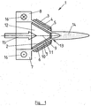
- Fig. 1 sketched plasma generator 1 is shown without a necessary for its operation alternating high voltage generator.
- This alternating high-voltage generator applies a high alternating voltage between a funnel-shaped, ie more precisely truncated cone-shaped electrode 2 and a likewise funnel-shaped, ie more precisely frost-shaped, counter-electrode 3.
- a corresponding funnel-shaped dielectric 4 and a hollow funnel-shaped discharge space 5 are arranged between the electrodes 2 and 3, specifically in front of the counterelectrode 3.
- the alternating high voltage therefore causes a dielectrically impeded discharge in a gas 6 flowing through the discharge space 5.
- the discharge space 5 is at the same time a gas guide channel 7 for the gas 6, which starts here from an annular space 8, extends along an axis 9 and ends on this axis 9.
- the gas guide channel 7 is limited to the outside by the dielectric 4 as a truncated cone-shaped wall 10 and inwardly through this wall 10 opposite frustoconical surface 11 of the electrode 2.
- the electrode 2 is arranged annularly around the axis 9 and leaves in the region of this axis. 9 a free working channel 12, which extends with a free cross section up to the gas guide channel 7, specifically up to the end 13, at the free end of the truncated cone-shaped wall 10.
- a gas flow from the annular space 8 through the gas guide channel 7 forms before the end 13 of a free jet 14, which contains plasma-typical energetically excited species.
- a further gas to be treated or to be added to a plasma treatment particles and / or electromagnetic radiation can be supplied.
- electromagnetic radiation from the area of the free jet 14 can also be received and analyzed.
- Fig. 1 indicated that in the annular space 8, a ring flow 16 of the gas 7 is formed to hereby take on the flow of the gas guide channel 7 with the gas 6 influence.
- the plasma generator 1 according to Fig. 1 used to treat a surface 17 of an object 18.
- the surface 17 is electrically conductive and at ground potential - between the surface 17 and the electrode 2 one or more discharge filaments 19 from.
- the plasma-generating discharge can also be focused entirely on the area between the electrode 2 and the surface 17 by applying the AC high voltage with the AC high voltage generator therebetween and dispense with a connection of the counter electrode 3 with the AC high voltage generator.
- the surface 17 can be treated simultaneously with the plasma with laser light, or with the optical fiber 20 light is received from the area of the treatment of the surface 17 with the plasma, for example, to monitor this treatment.
- Fig. 3 sketched a concrete embodiment of the plasma generator 1.
- the truncated cone-shaped wall and the opposite this truncated cone-shaped surface 11 of the electrode 2 each have a cone angle of 60 °.
- the free diameter of the working channel 12 at its free end is also the same size as the free inner diameter of the truncated cone-shaped wall 10 at its free end.
- the distance of the truncated cone-shaped wall 10 is matched to the truncated cone-shaped surface 11 so that in the entire gas guide channel 7 to the end 13 no stagnation point is created by the larger amounts of gas 6 would be pressed into the working channel 12.
- the embodiment of the plasma generator 1 according to Fig. 4 differs from the one according to Fig. 3 in the detail that adjoins the truncated cone-shaped wall 10 an opening 21 of the gas guide channel 7 with a cylindrical free cross-section.
- a free jet emerging from the plasma generator 1 can be further stabilized, which, however, is generally not required given favorable flow conditions of the gas 7 by the plasma generator 1.
- Such an orifice 21 of the gas guide channel 7 with a cylindrical free cross-section can also be useful for other reasons than beam stabilization, z. B. to provide security against contact with the internal electrode 2 or maintain a desired working distance.
Landscapes
- Physics & Mathematics (AREA)
- Engineering & Computer Science (AREA)
- Plasma & Fusion (AREA)
- Spectroscopy & Molecular Physics (AREA)
- Plasma Technology (AREA)
Description
- Die Erfindung bezieht sich auf einen Plasmagenerator mit den Merkmalen des Oberbegriffs des unabhängigen Patentanspruchs 1.
- Unter einem Plasmagenerator ist hier eine Vorrichtung zu verstehen, mit der ein physikalisches Plasma, d. h. ein energetisch angeregter Zustand eines Gases, das dem Plasmagenerator zugeführt wird, hervorgerufen werden kann. Ein solches aus dem Plasmagenerator austretendes physikalisches Plasma kann zum Beispiel zur Aktivierung von Oberflächen verwendet werden. Innerhalb des Plasmagenerators kann teilchen- oder fadenförmiges Gut mit dem Plasma behandelt werden. Auch das dem Plasmagenerator zugeführte Gas selbst kann das Objekt der Plasmabehandlung sein.
- Aus der
DE 694 08 502 T2 ist ein Plasmagenerator bekannt. Es handelt sich um eine Plasmaspritzpistole, die eine rohrförmige Anode mit abschnittsweise kegelstumpfmantelförmigen Innenflächen und eine koaxial in der rohrförmigen Anode angeordnete Kathode aufweist. Die Kathode ist massiv ausgebildet und weist an ihrem freien Ende hinter einer abgerundeten Spitze eine einem der kegelstumpfmantelförmigen Abschnitte der rohrförmigen Kathode gegenüberliegende kegelstumpfmantelförmige Oberfläche auf. Vor dem freien Ende der Kathode befindet sich ein Abschnitt der rohrförmigen Anode mit zylindrischem freiem Querschnitt, der länger als jeder kegelstumpfmantelförmige Abschnitt der rohrförmigen Anode ist. Dieser Plasmageneraior wird in derDE 694 08 502 T2 als Stand der Technik angegeben. - Bei der dort als Erfindung beschriebenen Plasmaspritzpistole weist der Abschnitt der rohrförmigen Anode, der um die kegelstumpfmantelförmige Oberfläche der Kathode angeordnet ist, die Form eines Zylindermantels auf.
- Ein Plasmagenerator mit einer massiven Elektrode auf der Achse des Gasführungskänals, die hier als Anode ausgebildet ist, und mit einem Abschnitt des .Gasführungskanals mit zylindrischem freiem Querschnitt, der an das freie Ende der Elektrode anschließt, ist auch aus der
EP 0 342 388 A2 bekannt. - Aus der
US 6,986,471 B1 ist ein Plasmasprühverfahren bekannt, bei dem zunächst ein Plasma generiert wird, das dann in einer Düsenanordnung mit einem Trägergas vermischt wird, in welchem Partikel dispergiert sind. Diese Düsenanordnung weist für das Trägergas einen Hohltrichter auf, der auf die Mündung einer Expansionsdüse zuläuft, aus welcher das Plasma austritt. - Aus der
DE 20 2009 000 537 U1 ist ein Plasmagenerator zur Erzeugung eines gebündelten Plasmastrahls bekannt, bei dem in einem um eine Stiftelektrode herum ausgebildeten Gasführungskanal Mittel zur Erzeugung einer Wirbelströmung um die Achse des Gasführungskanals herum ausgebildet sind. Vor dem freien Ende der Stiftelektrode weist der Gasführungskanal einen Abschnitt mit einer kegelstumpfmantelförmigen Wandung auf, bis er an einer ringförmigen Gegenelektrode endet. - Aus der
WO 2007/080102 A1 ist ein Verfahren zur Behandlung einer Oberfläche, insbesondere um diese von Verunreinigungen zu befreien, bekannt, wobei die Oberfläche gleichzeitig Laserlicht und einem durch elektrische Hochspannung induzierten physikalischen Plasma ausgesetzt wird. Dabei wird das Laserlicht zusammen mit einem freien Arbeitsgasstrom zwischen zwei Elektroden der Plasmaquelle hindurch in den Behandlungsbereich gerichtet. Die Elektroden sind stabförmig und parallel zueinander sowie parallel zu der Oberfläche ausgerichtet. - Aus der
US 2006/0043075 A1 ist eine Vorrichtung mit einem Plasmagenerator bekannt. Der Plasmagenerator weist eine Elektrodenplatte mit einer zentralen Öffnung auf. Diese Öffnung bildet den Augang des Plasmagenerators für Plasma und zugleich einen Austritt für einen einergiereichen Strahl aus, der stromauf in den Plasmagenerätor eingekoppelt wird und den das Plasma in radialer Richtung abschirmen soll. In der Elektrodenplatte ist ein Plasmaejektor um die zentrale Öffnung ausgebildet, der von Ejektorgas durchströmt wird. Dieser Plasmaejektor weist einen Gasführungskanal zwischen einer äußeren kegelstumpfmantelförmigen Wandung und einer inneren kegelstumpfmantelförmigen Wandung auf, wobei beide kegelstumpfmantelförmigen Wandungen von der Elektrodenplatte ausgebildet sind und wobei der Kegelwinkel der äußeren kegelstumpfmantelförmigen Wandung kleiner ist als derjenige der inneren kegelstumpfmantelförmigen Wandung. Bei der bekannten Vorrichtung dient das Plasma zur Abschirmung eines energiereichen Strahls beispielsweise von einem Laser. Das Plasma selbst wird hinter dem Plasmajektor in einem Wirbelgenerator mit einem umlaufenden Wirbel aus einem weiteren Fluid ummantelt. - Ein kombinierter Laser- und Plasmabogenschweißbrenner, der die Merkmale des Oberbegriffs des unabhängigen Patentspruchs 1 aufweist, ist aus der
US 5,705,785 A bekannt. Hier ist eine hohle Kathode koaxial innerhalb einer ersten Düse angeordnet, die wiederum koaxial innerhalb einer äußeren Abschirmdüse angeordnet ist. Die hohle Kathode und die Düsen werden an ihren vorderen Enden durch kegelstumpfmantelförmige Wandungen begrenzt. Durch die hohle Kathode wird ein Laserstrahl geführt, der zum Teil die Spitze der Kathode erhitzt und zum Teil vorne aus der Kathode austritt. Zwischen der hohlen Kathode und der ersten Düse wird ein Plasmagas zugeführt, und zwischen der ersten Düse und der Abschirnndüse wird ein Schutzgas zugeführt. Das Plasma wird durch einen Entladungsbogen zwischen der Kathode und einem Werkstück oder zwischen der Kathode und der Abschirmdiode unter gleichzeitiger Einwirkung des Laserstrahls erzeugt. - Aus der
WO 03/010088 A1 - Aus der
US 2004/022669 A1 ist eine nichtthermische Desinfektion von biologischen Fluiden unter Anwendung eines nicht thermischen Plasmas bekannt. Dazu kann ein Reaktor mit einem sich nach oben verjüngenden hohltrichterförmigen Reaktionsraum verwendet werden, der durch Wandungen aus einem Dielektrikum begrenzt wird und über den zwischen einer kegelstumpfmantelförmigen inneren Elektrode und einer kegelsturüpfmantelförmigen äußeren Elektrode eine Wechselspannung angelegt wird. Durch den Reaktionsraum fließt ein zu behandelndes Flüssigkeits-Gas-Gemisch bis u seinem unteren Ende von größerem Durchmesser. - Der Erfindung liegt die Aufgabe zugrunde, einen Plasmagenerator mit den Merkmalen des Oberbegriffs des unabhängigen Patentanspruchs 1 aufzuzeigen, bei dem der Bereich des aus der Mündung des Gasführungskanals austretenden Plasmas ohne Störung des Plasmas zugänglich ist.
- Die Aufgabe der Erfindung wird durch einen Plasmagenerator mit den Merkmalen des unabhängigen Patentanspruchs 1 gelöst. Bevorzugte Ausführungsformen des neuen Plasmagenerators sind in den abhängigen Patentansprüchen definiert.
- Bei dem neuen Plasmagenerator erstreckt sich die koaxial innerhalb der kegelstumpfmantetförmigen Wandung angeordnete Elektrode ringförmig um die Achse, längs derer der Gasführungskanal in seinem Endbereich verläuft und auf der der Gasführungskanal endet. Dies ist hier gleichbedeutend damit, dass die den Gasführungskanal innerhalb der kegelstumpfmantelförmigen Wandung begrenzende kegelstumpfmantelförmige Oberfläche die Oberfläche eines ringförmigen Elements ist, wobei dieses ringförmige Element die Elektrode sein kann. In jedem Fall erstreckt sich ein zumindest für Licht einer Wellenlänge transparenter Arbeitskanal auf der Achse durch die Elektrode bis zu dem Gasführungskanal. Über diesen Arbeitskanal und den davor liegenden Abschnitt des Gasführungskanals ist der Bereich, in dem das Plasma aus dem Gasführungskanal austritt, von hinten her zumindest für das Licht dieser einen Wellenlänge zugänglich. Das Licht kann zeitgleich mit dem Plasma zur Behandlung einer Oberfläche verwendet werden. In umgekehrter Richtung kann Licht dieser Wellenlänge aus dem Bereich des Plasmas registriert werden, um das Plasma oder eine Behandlung einer Oberfläche mit dem Plasma zu überwachen; oder das Licht kann Informationen über das Material der Oberfläche geben.
- Vorzugsweise ist der Arbeitskanal nicht nur für Licht einer Wellenlänge transparent, sondern für Licht in einem größeren Bereich von Wellenlängen. Noch mehr bevorzugt ist es, wenn der Arbeitskanal bis zu dem Gasführungskanal einen freien Querschnitt aufweist. Damit können über den Arbeitskanal beispielsweise auch Gase oder Partikel in den Gasführungskanal injiziert bzw. in ein dort ausgebildetes Plasma eingebracht werden.
- Wenn der Arbeitskanal einen freien Querschnitt aufweist, ist es bevorzugt, einen Kegelwinkel der den Gasführungskanal begrenzenden kegelstumpfmantelförmigen Wandung, einen Kegelwinkel der innerhalb der kegelstumpfmantelförmigen Wandung angeordneten kegelstumpfmantelförmigen Oberfläche, einen Abstand der kegelstumpfmantelförmigen Wandung von der kegelstumpfmantelförmigen Oberfläche und einen freien Endquerschnitt der kegelstumpfmantelförmige Wandung so zu wählen, dass sich keine oder allenfalls eine verglichen mit der Gesamtgasströmung nur kleine Gasströmung aus dem Gasführungskanal in den Arbeitskanals hinein ausbildet. Idealerweise bildet sich daher kein Staupunkt in dem Gasführungskanal aus, von dem aus ein Druckgefälle zu dem und in den Arbeitskanal verläuft. Maßnahmen, die zur Vermeidung oder zumindest Reduzierung eines solchen Staupunkts beitragen, bestehen in einem ausreichend kleinen Öffnungswinkel der kegelstumpfmantelförmigen Wandung und der kegelstumpfmantelförmigen Oberfläche sowie in einem ausreichend freien Endquerschnitt der kegelstumpfmantelförmigen Wandung. Dieser freie Endquerschnitt sollte auch nicht kleiner als der freie Querschnitt des Arbeitskanals sein.
- Die der kegelstumpfmantelförmigen Wandung zugewandte, ihrerseits kegelstumpfmantelförmige Oberfläche kann zumindest teilweise von der ringförmigen Elektrode oder einem auf der ringförmigen Elektrode angeordneten Dielektrikum ausgebildet sein. Vorzugsweise ist die Elektrode zumindest an dem freien Ende der kegelstumpfmantelförmigen Oberfläche vorgesehen. Sie kann sich aber auch - ggf. unterhalb eines sie bedeckenden Dielektrikums - über die gesamte Erstreckung der kegelstumpfmantelförmigen Oberfläche längs der Achse des Gasführüngskanals erstrecken.
- Die den Gasführungskanal nach außen begrenzende, kegelstumpfmantelförmige Wandung des neuen Plasmagenerators ist vorzugsweise aus einem Dielektrikum ausgebildet. Dabei kann die kegelstumpfmantelförmige Gegenelektrode außen auf zumindest einem Teil der kegelstumpfmantelförmigen Wandung angeordnet sein. Im Fall des Vorhandenseins einer solchen Gegenelektrode kann das Plasma in dem neuen Plasmagenerator zwischen der Elektrode und der Gegenelektrode und damit in dem hohltrichterförmigen Abschnitt des Gasführungskanals zwischen der kegelstumpfmantelförmigen Oberfläche und der kegelstumpfmantelförmigen Wandung ausgebildet werden.
- Die kegelstumpfmantelförmige Wandung und die kegelstumpfmantelförmige Oberfläche weisen einen zumindest in etwa gleichen Kegelwinkel auf, so dass der Abstand der kegelstumpfmantelförmigen Wandung von der kegelstumpfmantelförmigen Oberfläche im Wesentlichen konstant ist und sich entsprechend über die gesamte Länge des Gasführungskanals in seinem hohltrichterförmigen Abschnitt etwa gleiche Feldstärken des elektrischen Felds zwischen den Elektroden ausbilden.
- Der Gasführungskanal des neuen Plasmagenerators kann unmittelbar mit der kegelstumpfmantelförmigen Wandung enden. Überraschenderweise stellt sich auch dann ein stabiler Freistrahl des den Gasführungskanal durchströmenden Gases ein, in dem das Plasma ausgebildet wird. Dabei ist der Austrittspunkt dieses Freistrahls nur wenig von dem Ort der Erzeugung des Plasmas zwischen der Elektrode und einer im Bereich der kegelstumpfmantelförmigen Wandung angeordneten Gegenelektrode entfernt, so dass sich viele energetisch angeregte Spezies des Plasmas in dem Freistrahl erhalten und nicht bereits zuvor eine Wiederabregung erfahren.
- Bei dem neuen Plasmagenerator kann mindestens ein Gaszufuhrkanal mit einer Tangentialkomponente in den Gasführungskanal einmünden, um auf diese Weise die Strömungsverhältnisse in dem Gasführungskanal zu beeinflussen. Der mindestens eine Gaszufuhrkanal kann zum Beispiel unmittelbar in den erfindungsgemäß ausgebildeten Endbereich des Gasführungskanals oder aber in einen stromauf davon angeordneten Ringraum einmünden. Zusätzlich oder alternativ können in dem Endbereich des Gasführungskanals Gasführungselemente vorgesehen sein, die eine Führungskomponente in Umfangsrichtung um die Achse des Gasführungskanals aufweisen.
- Neben seinem bisher beschriebenen physikalischen Aufbau benötigt der neue Plasmagenerator zu seinem Betrieb einen Wechselhochspannungsgenerator, der die Elektrode mit einer Wechselhochspannung beaufschlagt. Vorzugsweise weist die Wechselhochspannung bipolare Spannungspulse auf. Aufbringen kann der Wechselhochspannungsgenerator Spannungspulse für die Elektrode gegenüber Erde, gegenüber einer im Bereich der kegelstumpfmantelförmigen Wandung des Gasführungskanals angeordneten Gegenelektrode oder gegenüber einer mit dem Plasma zu behandelnden Oberfläche.
- Vorteilhafte Weiterbildungen der Erfindung ergeben sich aus den Patentansprüchen, der Beschreibung und den Zeichnungen. Die in der Beschreibungseinleitung genannten Vorteile von Merkmalen und von Kombinationen mehrerer Merkmale sind lediglich beispielhaft und können alternativ oder kumulativ zur Wirkung kommen, ohne dass die Vorteile zwingend von erfindungsgemäßen Ausführungsformen erzielt werden müssen. Weitere Merkmale sind den Zeichnungen - insbesondere den dargestellten Geometrien und den relativen Abmessungen mehrerer Bauteile zueinander sowie deren relativer Anordnung und Wirkverbindung - zu entnehmen. Die Kombination von Merkmalen unterschiedlicher Ausführungsformen der Erfindung oder von Merkmalen unterschiedlicher Patentansprüche ist ebenfalls abweichend von den gewählten Rückbeziehungen der Patentansprüche möglich und wird hiermit angeregt. Dies betrifft auch solche Merkmale, die in separaten Zeichnungen dargestellt sind oder bei deren Beschreibung genannt werden. Diese Merkmale können auch mit Merkmalen unterschiedlicher Patentansprüche kombiniert werden. Ebenso können in den Patentansprüchen aufgeführte Merkmale für weitere Ausführungsformen der Erfindung entfallen.
- Die Erfindung wird im Folgenden anhand von Ausführungsbeispielen unter Bezugnahme auf die beigefügten Zeichnungen näher erläutert und beschrieben.
- Fig.1
- skizziert eine erste Ausführungsform des neuen Plasmagenerators in einer ersten Betriebsweise.
- Fig. 2
- skizziert die Ausführungsform des Plasmagenerators gemäß
Fig. 1 in einer zweiten Betriebsweise. - Fig. 3
- skizziert eine zweite Ausführungsform des neuen Plasmagenerators; und
- Fig. 4
- skizziert eine dritte Ausführungsform des neuen Plasmagenerators.
- Der in
Fig. 1 skizzierte Plasmagenerator 1 ist ohne einen zu seinem Betrieb notwendigen Wechselhochspannungsgenerator dargestellt. Dieser Wechselhochspannungsgenerator legt eine Wechselhochspannung zwischen einer trichterförmigen, d. h. genauer kegelstumpfmantelförmigen Elektrode 2 und einer ebenfalls trichterförmigen, d. h. genauer kegetstumpfmanteförmigen Gegenelektrode 3 an. Dabei sind zwischen den Elektroden 2 und 3, hier konkret vor der Gegenelektrode 3, ein entsprechend trichterförmiges Dielektrikum 4 und ein hohltrichterförmiger Entladungsraum 5 angeordnet. Die Wechselhochspannung ruft daher in einem durch den Entladungsraum 5 strömenden Gas 6 eine dielektrisch behinderte Entladung hervor. Der Entladungsraum 5 ist zugleich ein Gasführungskanal 7 für das Gas 6, der hier von einem Ringraum 8 ausgeht, sich längs einer Achse 9 erstreckt und auf dieser Achse 9 endet. Dabei wird der Gasführungskanal 7 nach außen durch das Dielektrikum 4 als kegelstumpfmantelförmige Wandung 10 begrenzt und nach innen durch die dieser Wandung 10 gegenüberliegende kegelstumpfmantelförmige Oberfläche 11 der Elektrode 2. Die Elektrode 2 ist ringförmig um die Achse 9 herum angeordnet und belässt im Bereich dieser Achse 9 einen freien Arbeitskanal 12, der sich mit freiem Querschnitt bis zu dem Gasführungskanal 7, konkret bis zu dessen Ende 13, am freien Ende der kegelstumpfmantelförmigen Wandung 10 erstreckt. Bei einer Gasströmung aus dem Ringraum 8 durch den Gasführungskanal 7 bildet sich vor dem Ende 13 ein Freistrahl 14 aus, der Plasma-typische energetisch angeregte Spezies enthält. Über den Arbeitskanal 12 können in Richtung eines Pfeils 15 ein weiteres Gas, zu behandelnde oder einer Plasmabehandlung hinzuzufügende Partikel und/oder elektromagnetische Strahlung zugeführt werden. In umgekehrter Richtung zu dem Pfeil 15 kann auch elektromagnetische Strahlung aus dem Bereich des Freistrahls 14 empfangen und analysiert werden. Weiter ist inFig. 1 angedeutet, dass in dem Ringraum 8 eine Ringströmung 16 des Gases 7 ausgebildet wird, um hiermit auf die Durchströmung des Gasführungskanals 7 mit dem Gas 6 Einfluss zu nehmen. - Gemäß
Fig. 2 wird der Plasmagenerator 1 gemäßFig. 1 zum Behandeln einer Oberfläche 17 eines Objekts 18 verwendet. Dabei bilden sich - insbesondere dann, wenn die Oberfläche 17 elektrisch leitend ist und auf Erdpotential liegt - zwischen der Oberfläche 17 und der Elektrode 2 ein oder mehrere Entladungsfilamente 19 aus. Die Plasma generierende Entladung kann auch ganz auf den Bereich zwischen der Elektrode 2 und der Oberfläche 17 fokussiert werden, indem die Wechselhochspannung mit dem Wechselhochspannungsgenerator dazwischen angelegt wird und auf eine Verbindung der Gegenelektrode 3 mit dem Wechselhochspannungsgenerator verzichtet wird. Über eine optische Faser 20 kann die Oberfläche 17 gleichzeitig mit dem Plasma mit Laserlicht behandelt werden, oder mit der optischen Faser 20 wird Licht aus dem Bereich der Behandlung der Oberfläche 17 mit dem Plasma empfangen, um beispielsweise diese Behandlung zu überwachen. -
Fig. 3 skizziert eine konkrete Ausführungsform des Plasmagenerators 1. Hier weisen die kegelstumpfmantelförmige Wandung die und die dieser gegenüberliegenden kegelstumpfmantelförmige Oberfläche 11 der Elektrode 2 jeweils einen Kegelwinkel von 60° auf. Der freie Durchmesser des Arbeitskanals 12 an seinem freien Ende ist zudem genauso groß wie der freie Innendurchmesser der kegelstumpfmantelförmigen Wandung 10 an deren freiem Ende. Zudem ist der Abstand der kegelstumpfmantelförmigen Wandung 10 zu der kegelstumpfmantelförmigen Oberfläche 11 so abgestimmt, dass in dem gesamten Gasführungskanal 7 bis zu dem Ende 13 kein Staupunkt entsteht, durch den größere Mengen des Gases 6 in den Arbeitskanal 12 gedrückt würde. - Die Ausführungsform des Plasmagenerators 1 gemäß
Fig. 4 unterscheidet sich von derjenigen gemäßFig. 3 in dem Detail, dass sich an die kegelstumpfmantelförmige Wandung 10 eine Mündung 21 des Gasführungskanals 7 mit zylindrischem freiem Querschnitt anschließt. Hiermit kann ein aus dem Plasmagenerator 1 austretender Freistrahl weiter stabilisiert werden, was jedoch bei günstigen Strömungsverhältnissen des Gases 7 durch den Plasmagenerator 1 in der Regel nicht erforderlich ist. Eine solche Mündung 21 des Gasführungskanals 7 mit zylindrischem freiem Querschnitt kann aber auch aus anderen Gründen als einer Strahlstabilisierung sinnvoll sein, z. B. um Sicherheit gegen einen Kontakt mit der innen liegenden Elektrode 2 bereitzustellen oder einen gewünschten Arbeitsabstand einzuhalten. -
- 1
- Plasmagenerators
- 2
- Elektrode
- 3
- Gegenelektrode
- 4
- Dielektrikum
- 5
- Entladungsraum
- 6
- Gas
- 7
- Gasführungskanal
- 8
- Ringraum
- 9
- Achse
- 10
- Wandung
- 11
- Oberfläche
- 12
- Arbeitskanal
- 13
- Ende
- 14
- Freistrahl
- 15
- Pfeil
- 16
- Ringströmung
- 17
- Oberfläche
- 18
- Objekt
- 19
- Entladungsfilament
- 20
- optische Faser
- 21
- Mündung
Claims (11)
- Plasmagenerator (1) mit einem Gasführungskanal (7), der in einem Endbereich längs einer Achse (9) verläuft und mit einem Ende (13) auf dieser Achse (9) endet, mit einer zumindest einen Abschnitt des Endbereichs des Gasführungskanals (7) radial nach außen begrenzenden, kegelstumpfmantelförmigen Wandung (10), mit einer koaxial innerhalb der kegelstumpfmantelförmigen Wandung (10) angeordneten kegelstumpfmantelförmigen Elektrode (2), mit einer im Bereich der kegelstumpfmantelförmigen Wandung (10) angeordneten kegelstumpfmantelförmigen Gegenelektrode (3) und mit einem Hochspannungsgenerator, der die Elektrode (2) gegenüber der Gegenelektrode (3) mit einer Hochspannung beaufschlagt, wobei der Gasführungskanal (7) zumindest in dem Abschnitt des Endbereichs nach innen durch eine der kegelstumpfmantelförmigen Wandung (10) zugewandte, koaxial zu dieser angeordnete, kegelstumpfmantelförmige Oberfläche (11) begrenzt ist, wobei sich die Elektrode (2) ringförmig um die Achse (9) erstreckt und wobei sich ein zumindest für Licht einer Wellenlänge transparenter Arbeitskanal (12) auf der Achse (9) durch die Elektrode (2) bis zu dem Gasführungskanal (7) erstreckt, dadurch gekennzeichnet,- dass die kegelstumpfmantelförmige Wandung (10) und die kegelstumpfmantelförmige Oberfläche (11) einen gleichen Kegelwinkel aufweisen und einen hohltrichterförmigen Entladungsraum (5) begrenzen,- dass ein auf der Elektrode (2) angeordnetes Dielektrikum die der kegelstumpfmantelförmigen Wandung (10) zugewandte, kegelstumpfmantelförmige Oberfläche (11) ausbildet und/oder die kegelstumpfmantelförmige Wandung (10) aus einem Dielektrikum (4) ausgebildet ist und- dass der Hochspannungsgenerator ein Wechselhochspannungsgenerator ist und eine Wechselhochspannung zwischen der Elektrode (2) und der Gegenelektrode (3) anlegt, die in einem durch den Entladungsraum (5) strömenden Gas (6) eine dielektrisch behinderte Entladung hervorruft, so dass am Ende (13) des Gasführungskanals (7) ein Freistrahl austritt, der Plasma-typische energetisch angeregte Spezies enthält.
- Plasmagenerator (1) nach Anspruch 1, dadurch gekennzeichnet, dass der Arbeitskanal (12) bis zu dem Gasführungskanal (7) einen freien Querschnitt aufweist.
- Plasmagenerator (1) nach Anspruch 2, dadurch gekennzeichnet, dass der Kegelwinkel der kegelstumpfmantelförmigen Wandung (10) und der kegelstumpfmantelförmigen Oberfläche (11), ein Abstand der kegelstumpfmantelförmigen Oberfläche (11) von der kegelstumpfmantelförmigen Wandung (10) und ein freier Endquerschnitt der kegelstumpfmantelförmigen Wandung (10) so gewählt sind, dass sich keine Gasströmung aus dem Gasführungskanal (7) in den Arbeitskanal (12) hinein ausbildet.
- Plasmagenerator (1) nach einem der vorhergehenden Ansprüche, wobei die kegelstumpfmantelförmige Wandung (10) aus einem Dielektrikum (4) ausgebildet ist, dadurch gekennzeichnet, dass die kegelstumpfmantelförmige Gegenelektrode (3) außen auf der kegelstumpfmantelförmigen Wandung (10) angeordnet ist.
- Plasmagenerator (1) nach einem der vorhergehenden Ansprüche 1 bis 3, wobei ein auf der Elektrode (2) angeordnetes Dielektrikum die der kegelstumpfmantelförmigen Wandung (10) zugewandte, kegelstumpfmantelförmige Oberfläche (11) ausbildet, dadurch gekennzeichnet, dass die kegelstumpfmantelförmige Wandung (10) als Gegenelektrode (3) ausgebildet ist.
- Plasmagenerator (1) nach einem der vorhergehenden Ansprüche, dadurch gekennzeichnet, dass der Gasführungskanal (7) mit der kegelstumpfmantelförmigen Wandung (10) endet.
- Plasmagenerator (1) nach einem der vorhergehenden Ansprüche 1 bis 5, dadurch gekennzeichnet, dass sich eine Mündung (21) des Gasführungskanals (6) mit zylindrischem freiem Querschnitt an die kegelstumpfmantelförmige Wandung (10) anschließt, wobei ein Innendurchmesser der Mündung und ein minimaler Innendurchmesser der kegelstumpfmantelförmigen Wandung (10) gleich groß sind.
- Plasmagenerator (1) nach einem der vorhergehenden Ansprüche, dadurch gekennzeichnet, dass mindestens ein Gaszufuhrkanal mit einer Tangentialkomponente in den Gasführungskanal (7) einmündet.
- Plasmagenerator (1) nach Anspruch 8, dadurch gekennzeichnet, dass der mindestens eine Gaszufuhrkanal in den Endbereich des Gasführungskanals (6) oder in einen stromauf davon angeordneten Ringraum (8) einmündet.
- Plasmagenerator (1) nach einem der vorhergehenden Ansprüche, dadurch gekennzeichnet, dass in dem Endbereich Gasführungselemente mit einer Führungskomponente in Umfangsrichtung um die Achse (9) vorgesehen sind.
- Plasmagenerator (1) nach einem der vorhergehenden Ansprüche, dadurch gekennzeichnet, dass der Wechselhochspannungsgenerator die Elektrode (2) mit bipolaren Spannungspulsen beaufschlagt.
Applications Claiming Priority (2)
| Application Number | Priority Date | Filing Date | Title |
|---|---|---|---|
| DE102010001606A DE102010001606A1 (de) | 2010-02-04 | 2010-02-04 | Hohltrichterförmiger Plasmagenerator |
| PCT/EP2010/069123 WO2011095245A1 (de) | 2010-02-04 | 2010-12-08 | Hohltrichterförmiger plasmagenerator |
Publications (2)
| Publication Number | Publication Date |
|---|---|
| EP2532214A1 EP2532214A1 (de) | 2012-12-12 |
| EP2532214B1 true EP2532214B1 (de) | 2016-03-23 |
Family
ID=43827574
Family Applications (1)
| Application Number | Title | Priority Date | Filing Date |
|---|---|---|---|
| EP10788326.6A Not-in-force EP2532214B1 (de) | 2010-02-04 | 2010-12-08 | Hohltrichterförmiger plasmagenerator |
Country Status (3)
| Country | Link |
|---|---|
| EP (1) | EP2532214B1 (de) |
| DE (1) | DE102010001606A1 (de) |
| WO (1) | WO2011095245A1 (de) |
Families Citing this family (2)
| Publication number | Priority date | Publication date | Assignee | Title |
|---|---|---|---|---|
| DE102017118652A1 (de) | 2017-08-16 | 2019-02-21 | Hochschule Für Angewandte Wissenschaft Und Kunst Hildesheim/Holzminden/Göttingen | Plasmageneratormodul und dessen Verwendung |
| JP2022538202A (ja) * | 2020-05-22 | 2022-09-01 | フン リ,チャン | 大気圧プラズマ発生装置を用いた円筒状及び環状の被処理物の表面処理システム及び方法 |
Family Cites Families (12)
| Publication number | Priority date | Publication date | Assignee | Title |
|---|---|---|---|---|
| US3719829A (en) * | 1970-04-10 | 1973-03-06 | Versar Inc | Laser beam techniques |
| US4841114A (en) | 1987-03-11 | 1989-06-20 | Browning James A | High-velocity controlled-temperature plasma spray method and apparatus |
| US5444209A (en) | 1993-08-11 | 1995-08-22 | Miller Thermal, Inc. | Dimensionally stable subsonic plasma arc spray gun with long wearing electrodes |
| US5705785A (en) * | 1994-12-30 | 1998-01-06 | Plasma-Laser Technologies Ltd | Combined laser and plasma arc welding torch |
| DE10065629C1 (de) * | 2000-12-21 | 2002-08-29 | Fraunhofer Ges Forschung | Vorrichtung zur Beschichtung eines Substrates mit einem Plasmabrenner |
| US7011790B2 (en) * | 2001-05-07 | 2006-03-14 | Regents Of The University Of Minnesota | Non-thermal disinfection of biological fluids using non-thermal plasma |
| CA2353752A1 (en) * | 2001-07-25 | 2003-01-25 | Precisionh2 Inc. | Production of hydrogen and carbon from natural gas or methane using barrier discharge non-thermal plasma |
| US6986471B1 (en) | 2002-01-08 | 2006-01-17 | Flame Spray Industries, Inc. | Rotary plasma spray method and apparatus for applying a coating utilizing particle kinetics |
| JP2006515708A (ja) * | 2003-01-31 | 2006-06-01 | ダウ・コーニング・アイルランド・リミテッド | プラズマ発生アセンブリ |
| US7075030B2 (en) * | 2004-08-30 | 2006-07-11 | Brookhaven Science Associates, Llc | Shielded beam delivery apparatus and method |
| DE102006001891B3 (de) | 2006-01-14 | 2007-12-20 | Fachhochschule Hildesheim/Holzminden/Göttingen | Verfahren und Vorrichtung zur Behandlung einer Oberfläche, insbesondere um diese von Verunreinigungen zu befreien |
| DE202009000537U1 (de) | 2009-01-14 | 2009-04-02 | Reinhausen Plasma Gmbh | Strahlgenerator zur Erzeugung eines gebündelten Plasmastrahls |
-
2010
- 2010-02-04 DE DE102010001606A patent/DE102010001606A1/de not_active Withdrawn
- 2010-12-08 EP EP10788326.6A patent/EP2532214B1/de not_active Not-in-force
- 2010-12-08 WO PCT/EP2010/069123 patent/WO2011095245A1/de not_active Ceased
Also Published As
| Publication number | Publication date |
|---|---|
| WO2011095245A1 (de) | 2011-08-11 |
| DE102010001606A1 (de) | 2011-08-04 |
| EP2532214A1 (de) | 2012-12-12 |
Similar Documents
| Publication | Publication Date | Title |
|---|---|---|
| DE3851965T2 (de) | Plasma-Operationsmesser. | |
| EP1236380B1 (de) | Plasmadüse | |
| DE102008018827B4 (de) | Vorrichtung zur Erzeugung eines Atmosphärendruck-Plasmas | |
| EP3387886B1 (de) | Vorrichtung zum erzeugen eines atmosphärischen plasmastrahls und verfahren zur behandlung der oberfläche eines werkstücks | |
| EP1994807B1 (de) | Vorrichtung zur erzeugung eines plasma-jets | |
| DE2059594A1 (de) | Verfahren und Vorrichtung zum elektrostatischen Aufstreuen von Farbstoffen,Pulvermaterial,Faserstoffen u.dgl. | |
| EP0994637A2 (de) | Verfahren zur Plasmabehandlung von stab- oder fadenförmigem Material | |
| DE102007011235A1 (de) | Verfahren und Vorrichtung zur Behandlung einer Oberfläche eines Werkstückes | |
| DE602004007126T2 (de) | Vorrichtung und verfahren zur bildung eines plasmas | |
| EP2382460B1 (de) | Verfahren und vorrichtung zur detektion von ionisierbaren gasen | |
| DE4340224A1 (de) | Einrichtung zum Erzeugen von Plasma mittels Mikrowellenstrahlung | |
| DE19962160C2 (de) | Vorrichtungen zur Erzeugung von Extrem-Ultraviolett- und weicher Röntgenstrahlung aus einer Gasentladung | |
| EP2130414B1 (de) | Vorrichtung und verfahren zur erzeugung eines plasmastrahls | |
| EP1767068A2 (de) | Vorrichtung zur bearbeitung eines substrates mittels mindestens eines plasma-jets | |
| DE202007018327U1 (de) | Vorrichtung zum Erzeugen eines Plasmas | |
| DE69603550T2 (de) | Plasmabrennerkopf und diesen enthaltender Plasmabrenner | |
| DE1660592A1 (de) | Blasstrahlduese zum Foerdern und/oder Behandeln textiler Fadengebilde | |
| EP2209354B1 (de) | Strahlgenerator zur Erzeugung eines gebündelten Plasmastrahls | |
| WO2011095245A1 (de) | Hohltrichterförmiger plasmagenerator | |
| DE202009000537U1 (de) | Strahlgenerator zur Erzeugung eines gebündelten Plasmastrahls | |
| DE102009004968B4 (de) | Strahlgenerator zur Erzeugung eines gebündelten Plasmastrahls | |
| DE10303402A1 (de) | Vorrichtung zum Erzeugen eines breiten Aktivgasstrahls auf Basis eines Gasentladungsplasmas | |
| DE1907530C3 (de) | Elektrostatische Spritzpistole | |
| DE102016201738A1 (de) | Beschichtungsvorrichtung | |
| DE1564123A1 (de) | Einrichtung zum Erzeugen eines heissen Plasmastrahles |
Legal Events
| Date | Code | Title | Description |
|---|---|---|---|
| PUAI | Public reference made under article 153(3) epc to a published international application that has entered the european phase |
Free format text: ORIGINAL CODE: 0009012 |
|
| 17P | Request for examination filed |
Effective date: 20120831 |
|
| AK | Designated contracting states |
Kind code of ref document: A1 Designated state(s): AL AT BE BG CH CY CZ DE DK EE ES FI FR GB GR HR HU IE IS IT LI LT LU LV MC MK MT NL NO PL PT RO RS SE SI SK SM TR |
|
| RAP1 | Party data changed (applicant data changed or rights of an application transferred) |
Owner name: FRAUNHOFER-GESELLSCHAFT ZUR FOERDERUNG DER ANGEWAN |
|
| DAX | Request for extension of the european patent (deleted) | ||
| RIC1 | Information provided on ipc code assigned before grant |
Ipc: H05H 1/24 20060101AFI20150630BHEP |
|
| GRAP | Despatch of communication of intention to grant a patent |
Free format text: ORIGINAL CODE: EPIDOSNIGR1 |
|
| INTG | Intention to grant announced |
Effective date: 20150902 |
|
| GRAS | Grant fee paid |
Free format text: ORIGINAL CODE: EPIDOSNIGR3 |
|
| GRAA | (expected) grant |
Free format text: ORIGINAL CODE: 0009210 |
|
| RAP1 | Party data changed (applicant data changed or rights of an application transferred) |
Owner name: FRAUNHOFER-GESELLSCHAFT ZUR FOERDERUNG DER ANGEWAN |
|
| RIN1 | Information on inventor provided before grant (corrected) |
Inventor name: WIENEKE, STEPHAN Inventor name: DAMM, ROLAND Inventor name: VIOEL, WOLFGANG Inventor name: BRUECKNER, STEPHAN |
|
| INTG | Intention to grant announced |
Effective date: 20160125 |
|
| AK | Designated contracting states |
Kind code of ref document: B1 Designated state(s): AL AT BE BG CH CY CZ DE DK EE ES FI FR GB GR HR HU IE IS IT LI LT LU LV MC MK MT NL NO PL PT RO RS SE SI SK SM TR |
|
| REG | Reference to a national code |
Ref country code: GB Ref legal event code: FG4D Free format text: NOT ENGLISH |
|
| REG | Reference to a national code |
Ref country code: CH Ref legal event code: EP |
|
| REG | Reference to a national code |
Ref country code: AT Ref legal event code: REF Ref document number: 784259 Country of ref document: AT Kind code of ref document: T Effective date: 20160415 |
|
| REG | Reference to a national code |
Ref country code: IE Ref legal event code: FG4D Free format text: LANGUAGE OF EP DOCUMENT: GERMAN |
|
| REG | Reference to a national code |
Ref country code: DE Ref legal event code: R096 Ref document number: 502010011285 Country of ref document: DE |
|
| REG | Reference to a national code |
Ref country code: LT Ref legal event code: MG4D |
|
| REG | Reference to a national code |
Ref country code: NL Ref legal event code: MP Effective date: 20160323 |
|
| PG25 | Lapsed in a contracting state [announced via postgrant information from national office to epo] |
Ref country code: FI Free format text: LAPSE BECAUSE OF FAILURE TO SUBMIT A TRANSLATION OF THE DESCRIPTION OR TO PAY THE FEE WITHIN THE PRESCRIBED TIME-LIMIT Effective date: 20160323 Ref country code: GR Free format text: LAPSE BECAUSE OF FAILURE TO SUBMIT A TRANSLATION OF THE DESCRIPTION OR TO PAY THE FEE WITHIN THE PRESCRIBED TIME-LIMIT Effective date: 20160624 Ref country code: NO Free format text: LAPSE BECAUSE OF FAILURE TO SUBMIT A TRANSLATION OF THE DESCRIPTION OR TO PAY THE FEE WITHIN THE PRESCRIBED TIME-LIMIT Effective date: 20160623 Ref country code: HR Free format text: LAPSE BECAUSE OF FAILURE TO SUBMIT A TRANSLATION OF THE DESCRIPTION OR TO PAY THE FEE WITHIN THE PRESCRIBED TIME-LIMIT Effective date: 20160323 |
|
| PG25 | Lapsed in a contracting state [announced via postgrant information from national office to epo] |
Ref country code: NL Free format text: LAPSE BECAUSE OF FAILURE TO SUBMIT A TRANSLATION OF THE DESCRIPTION OR TO PAY THE FEE WITHIN THE PRESCRIBED TIME-LIMIT Effective date: 20160323 Ref country code: LV Free format text: LAPSE BECAUSE OF FAILURE TO SUBMIT A TRANSLATION OF THE DESCRIPTION OR TO PAY THE FEE WITHIN THE PRESCRIBED TIME-LIMIT Effective date: 20160323 Ref country code: LT Free format text: LAPSE BECAUSE OF FAILURE TO SUBMIT A TRANSLATION OF THE DESCRIPTION OR TO PAY THE FEE WITHIN THE PRESCRIBED TIME-LIMIT Effective date: 20160323 Ref country code: RS Free format text: LAPSE BECAUSE OF FAILURE TO SUBMIT A TRANSLATION OF THE DESCRIPTION OR TO PAY THE FEE WITHIN THE PRESCRIBED TIME-LIMIT Effective date: 20160323 Ref country code: SE Free format text: LAPSE BECAUSE OF FAILURE TO SUBMIT A TRANSLATION OF THE DESCRIPTION OR TO PAY THE FEE WITHIN THE PRESCRIBED TIME-LIMIT Effective date: 20160323 |
|
| PG25 | Lapsed in a contracting state [announced via postgrant information from national office to epo] |
Ref country code: EE Free format text: LAPSE BECAUSE OF FAILURE TO SUBMIT A TRANSLATION OF THE DESCRIPTION OR TO PAY THE FEE WITHIN THE PRESCRIBED TIME-LIMIT Effective date: 20160323 Ref country code: PL Free format text: LAPSE BECAUSE OF FAILURE TO SUBMIT A TRANSLATION OF THE DESCRIPTION OR TO PAY THE FEE WITHIN THE PRESCRIBED TIME-LIMIT Effective date: 20160323 Ref country code: IS Free format text: LAPSE BECAUSE OF FAILURE TO SUBMIT A TRANSLATION OF THE DESCRIPTION OR TO PAY THE FEE WITHIN THE PRESCRIBED TIME-LIMIT Effective date: 20160723 |
|
| PG25 | Lapsed in a contracting state [announced via postgrant information from national office to epo] |
Ref country code: SM Free format text: LAPSE BECAUSE OF FAILURE TO SUBMIT A TRANSLATION OF THE DESCRIPTION OR TO PAY THE FEE WITHIN THE PRESCRIBED TIME-LIMIT Effective date: 20160323 Ref country code: CZ Free format text: LAPSE BECAUSE OF FAILURE TO SUBMIT A TRANSLATION OF THE DESCRIPTION OR TO PAY THE FEE WITHIN THE PRESCRIBED TIME-LIMIT Effective date: 20160323 Ref country code: RO Free format text: LAPSE BECAUSE OF FAILURE TO SUBMIT A TRANSLATION OF THE DESCRIPTION OR TO PAY THE FEE WITHIN THE PRESCRIBED TIME-LIMIT Effective date: 20160323 Ref country code: PT Free format text: LAPSE BECAUSE OF FAILURE TO SUBMIT A TRANSLATION OF THE DESCRIPTION OR TO PAY THE FEE WITHIN THE PRESCRIBED TIME-LIMIT Effective date: 20160725 Ref country code: ES Free format text: LAPSE BECAUSE OF FAILURE TO SUBMIT A TRANSLATION OF THE DESCRIPTION OR TO PAY THE FEE WITHIN THE PRESCRIBED TIME-LIMIT Effective date: 20160323 Ref country code: SK Free format text: LAPSE BECAUSE OF FAILURE TO SUBMIT A TRANSLATION OF THE DESCRIPTION OR TO PAY THE FEE WITHIN THE PRESCRIBED TIME-LIMIT Effective date: 20160323 |
|
| REG | Reference to a national code |
Ref country code: FR Ref legal event code: PLFP Year of fee payment: 7 |
|
| PG25 | Lapsed in a contracting state [announced via postgrant information from national office to epo] |
Ref country code: IT Free format text: LAPSE BECAUSE OF FAILURE TO SUBMIT A TRANSLATION OF THE DESCRIPTION OR TO PAY THE FEE WITHIN THE PRESCRIBED TIME-LIMIT Effective date: 20160323 |
|
| REG | Reference to a national code |
Ref country code: DE Ref legal event code: R097 Ref document number: 502010011285 Country of ref document: DE |
|
| PLBE | No opposition filed within time limit |
Free format text: ORIGINAL CODE: 0009261 |
|
| STAA | Information on the status of an ep patent application or granted ep patent |
Free format text: STATUS: NO OPPOSITION FILED WITHIN TIME LIMIT |
|
| PG25 | Lapsed in a contracting state [announced via postgrant information from national office to epo] |
Ref country code: DK Free format text: LAPSE BECAUSE OF FAILURE TO SUBMIT A TRANSLATION OF THE DESCRIPTION OR TO PAY THE FEE WITHIN THE PRESCRIBED TIME-LIMIT Effective date: 20160323 |
|
| PG25 | Lapsed in a contracting state [announced via postgrant information from national office to epo] |
Ref country code: BG Free format text: LAPSE BECAUSE OF FAILURE TO SUBMIT A TRANSLATION OF THE DESCRIPTION OR TO PAY THE FEE WITHIN THE PRESCRIBED TIME-LIMIT Effective date: 20160623 |
|
| 26N | No opposition filed |
Effective date: 20170102 |
|
| PG25 | Lapsed in a contracting state [announced via postgrant information from national office to epo] |
Ref country code: BE Free format text: LAPSE BECAUSE OF NON-PAYMENT OF DUE FEES Effective date: 20161231 Ref country code: SI Free format text: LAPSE BECAUSE OF FAILURE TO SUBMIT A TRANSLATION OF THE DESCRIPTION OR TO PAY THE FEE WITHIN THE PRESCRIBED TIME-LIMIT Effective date: 20160323 |
|
| REG | Reference to a national code |
Ref country code: CH Ref legal event code: PL |
|
| PG25 | Lapsed in a contracting state [announced via postgrant information from national office to epo] |
Ref country code: MC Free format text: LAPSE BECAUSE OF FAILURE TO SUBMIT A TRANSLATION OF THE DESCRIPTION OR TO PAY THE FEE WITHIN THE PRESCRIBED TIME-LIMIT Effective date: 20160323 |
|
| REG | Reference to a national code |
Ref country code: IE Ref legal event code: MM4A |
|
| PG25 | Lapsed in a contracting state [announced via postgrant information from national office to epo] |
Ref country code: LI Free format text: LAPSE BECAUSE OF NON-PAYMENT OF DUE FEES Effective date: 20161231 Ref country code: CH Free format text: LAPSE BECAUSE OF NON-PAYMENT OF DUE FEES Effective date: 20161231 Ref country code: LU Free format text: LAPSE BECAUSE OF NON-PAYMENT OF DUE FEES Effective date: 20161208 |
|
| PG25 | Lapsed in a contracting state [announced via postgrant information from national office to epo] |
Ref country code: IE Free format text: LAPSE BECAUSE OF NON-PAYMENT OF DUE FEES Effective date: 20161208 |
|
| REG | Reference to a national code |
Ref country code: FR Ref legal event code: PLFP Year of fee payment: 8 |
|
| REG | Reference to a national code |
Ref country code: BE Ref legal event code: MM Effective date: 20161231 |
|
| REG | Reference to a national code |
Ref country code: AT Ref legal event code: MM01 Ref document number: 784259 Country of ref document: AT Kind code of ref document: T Effective date: 20161208 |
|
| PG25 | Lapsed in a contracting state [announced via postgrant information from national office to epo] |
Ref country code: HU Free format text: LAPSE BECAUSE OF FAILURE TO SUBMIT A TRANSLATION OF THE DESCRIPTION OR TO PAY THE FEE WITHIN THE PRESCRIBED TIME-LIMIT; INVALID AB INITIO Effective date: 20101208 Ref country code: AT Free format text: LAPSE BECAUSE OF NON-PAYMENT OF DUE FEES Effective date: 20161208 Ref country code: CY Free format text: LAPSE BECAUSE OF FAILURE TO SUBMIT A TRANSLATION OF THE DESCRIPTION OR TO PAY THE FEE WITHIN THE PRESCRIBED TIME-LIMIT Effective date: 20160323 |
|
| PG25 | Lapsed in a contracting state [announced via postgrant information from national office to epo] |
Ref country code: MK Free format text: LAPSE BECAUSE OF FAILURE TO SUBMIT A TRANSLATION OF THE DESCRIPTION OR TO PAY THE FEE WITHIN THE PRESCRIBED TIME-LIMIT Effective date: 20160323 Ref country code: TR Free format text: LAPSE BECAUSE OF FAILURE TO SUBMIT A TRANSLATION OF THE DESCRIPTION OR TO PAY THE FEE WITHIN THE PRESCRIBED TIME-LIMIT Effective date: 20160323 |
|
| PG25 | Lapsed in a contracting state [announced via postgrant information from national office to epo] |
Ref country code: MT Free format text: LAPSE BECAUSE OF FAILURE TO SUBMIT A TRANSLATION OF THE DESCRIPTION OR TO PAY THE FEE WITHIN THE PRESCRIBED TIME-LIMIT Effective date: 20160323 |
|
| PG25 | Lapsed in a contracting state [announced via postgrant information from national office to epo] |
Ref country code: AL Free format text: LAPSE BECAUSE OF FAILURE TO SUBMIT A TRANSLATION OF THE DESCRIPTION OR TO PAY THE FEE WITHIN THE PRESCRIBED TIME-LIMIT Effective date: 20160323 |
|
| PGFP | Annual fee paid to national office [announced via postgrant information from national office to epo] |
Ref country code: GB Payment date: 20221222 Year of fee payment: 13 Ref country code: FR Payment date: 20221219 Year of fee payment: 13 |
|
| PGFP | Annual fee paid to national office [announced via postgrant information from national office to epo] |
Ref country code: DE Payment date: 20221221 Year of fee payment: 13 |
|
| P01 | Opt-out of the competence of the unified patent court (upc) registered |
Effective date: 20230524 |
|
| REG | Reference to a national code |
Ref country code: DE Ref legal event code: R119 Ref document number: 502010011285 Country of ref document: DE |
|
| GBPC | Gb: european patent ceased through non-payment of renewal fee |
Effective date: 20231208 |
|
| PG25 | Lapsed in a contracting state [announced via postgrant information from national office to epo] |
Ref country code: DE Free format text: LAPSE BECAUSE OF NON-PAYMENT OF DUE FEES Effective date: 20240702 |
|
| PG25 | Lapsed in a contracting state [announced via postgrant information from national office to epo] |
Ref country code: GB Free format text: LAPSE BECAUSE OF NON-PAYMENT OF DUE FEES Effective date: 20231208 |
|
| PG25 | Lapsed in a contracting state [announced via postgrant information from national office to epo] |
Ref country code: FR Free format text: LAPSE BECAUSE OF NON-PAYMENT OF DUE FEES Effective date: 20231231 |
|
| PG25 | Lapsed in a contracting state [announced via postgrant information from national office to epo] |
Ref country code: GB Free format text: LAPSE BECAUSE OF NON-PAYMENT OF DUE FEES Effective date: 20231208 Ref country code: FR Free format text: LAPSE BECAUSE OF NON-PAYMENT OF DUE FEES Effective date: 20231231 Ref country code: DE Free format text: LAPSE BECAUSE OF NON-PAYMENT OF DUE FEES Effective date: 20240702 |