EP2531759B1 - Gasdruckregler - Google Patents
Gasdruckregler Download PDFInfo
- Publication number
- EP2531759B1 EP2531759B1 EP11706009.5A EP11706009A EP2531759B1 EP 2531759 B1 EP2531759 B1 EP 2531759B1 EP 11706009 A EP11706009 A EP 11706009A EP 2531759 B1 EP2531759 B1 EP 2531759B1
- Authority
- EP
- European Patent Office
- Prior art keywords
- central body
- silencing device
- gas
- pressure regulator
- annular
- Prior art date
- Legal status (The legal status is an assumption and is not a legal conclusion. Google has not performed a legal analysis and makes no representation as to the accuracy of the status listed.)
- Active
Links
Images
Classifications
-
- F—MECHANICAL ENGINEERING; LIGHTING; HEATING; WEAPONS; BLASTING
- F16—ENGINEERING ELEMENTS AND UNITS; GENERAL MEASURES FOR PRODUCING AND MAINTAINING EFFECTIVE FUNCTIONING OF MACHINES OR INSTALLATIONS; THERMAL INSULATION IN GENERAL
- F16K—VALVES; TAPS; COCKS; ACTUATING-FLOATS; DEVICES FOR VENTING OR AERATING
- F16K47/00—Means in valves for absorbing fluid energy
- F16K47/08—Means in valves for absorbing fluid energy for decreasing pressure or noise level and having a throttling member separate from the closure member, e.g. screens, slots, labyrinths
-
- Y—GENERAL TAGGING OF NEW TECHNOLOGICAL DEVELOPMENTS; GENERAL TAGGING OF CROSS-SECTIONAL TECHNOLOGIES SPANNING OVER SEVERAL SECTIONS OF THE IPC; TECHNICAL SUBJECTS COVERED BY FORMER USPC CROSS-REFERENCE ART COLLECTIONS [XRACs] AND DIGESTS
- Y10—TECHNICAL SUBJECTS COVERED BY FORMER USPC
- Y10T—TECHNICAL SUBJECTS COVERED BY FORMER US CLASSIFICATION
- Y10T137/00—Fluid handling
- Y10T137/0318—Processes
- Y10T137/0396—Involving pressure control
-
- Y—GENERAL TAGGING OF NEW TECHNOLOGICAL DEVELOPMENTS; GENERAL TAGGING OF CROSS-SECTIONAL TECHNOLOGIES SPANNING OVER SEVERAL SECTIONS OF THE IPC; TECHNICAL SUBJECTS COVERED BY FORMER USPC CROSS-REFERENCE ART COLLECTIONS [XRACs] AND DIGESTS
- Y10—TECHNICAL SUBJECTS COVERED BY FORMER USPC
- Y10T—TECHNICAL SUBJECTS COVERED BY FORMER US CLASSIFICATION
- Y10T137/00—Fluid handling
- Y10T137/8376—Combined
-
- Y—GENERAL TAGGING OF NEW TECHNOLOGICAL DEVELOPMENTS; GENERAL TAGGING OF CROSS-SECTIONAL TECHNOLOGIES SPANNING OVER SEVERAL SECTIONS OF THE IPC; TECHNICAL SUBJECTS COVERED BY FORMER USPC CROSS-REFERENCE ART COLLECTIONS [XRACs] AND DIGESTS
- Y10—TECHNICAL SUBJECTS COVERED BY FORMER USPC
- Y10T—TECHNICAL SUBJECTS COVERED BY FORMER US CLASSIFICATION
- Y10T137/00—Fluid handling
- Y10T137/8593—Systems
- Y10T137/86493—Multi-way valve unit
- Y10T137/86718—Dividing into parallel flow paths with recombining
- Y10T137/86759—Reciprocating
Definitions
- This invention addresses the technical sector relating to gas regulators.
- the invention relates to a gas pressure regulator equipped with a silencing device.
- One prior art gas regulator comprises a central body in which an internal cavity is formed.
- the central body is connected to a first, gas inlet pipe and a second, gas outlet pipe.
- the regulator also comprises a shutter which is slidably fitted inside the cavity in the central body.
- the shutter is mobile in the direction of its axis to adjust the opening of the gas passage section.
- the shutter is mobile between a fully open position, where it allows the maximum flow of gas between the inlet pipe and the outlet pipe, and a closed position, where it engages with a seal which is inserted inside the central body and which is made of a compliant material (for example, rubber), to prevent the gas from flowing between the inlet pipe and the outlet pipe.
- a compliant material for example, rubber
- the pressure regulator also comprises a silencing device designed to reduce the noise generated in the gas regulator by known physical phenomena such as gas acceleration to a speed faster than sound, the formation of shock waves, etc.
- the silencing device comprises a mesh ring consisting of thin wire mesh and a pair of U-shaped edges on one side, which close the mesh.
- the wire mesh is securely crimped within the U-shaped section of the respective pair of edges.
- the silencing device thus made is mounted inside the central body, supported by a supporting element fixed to the central body.
- the mesh ring forms a forced passage for the gas between the inlet pipe and the outlet pipe.
- the mesh the ring is made from is not strong enough to resist high gas speeds and soon breaks.
- solid particles (such as dust or other debris) which may be carried by the gas leads to mesh wear and failure of the silencing device.
- This type of pressure regulator is not therefore suitable for gas flowing at high speeds or containing solid particles, even small diameter particles (where the expression "small diameter” includes particles even smaller than 5 ⁇ m in diameter).
- the mesh ring silencing device is replaced with a more robust silencing device capable of resisting high gas speeds.
- the silencing device consists of a hollow cylinder made from a section bar or a single block, suitably machined, with a plurality of holes for the passage of the gas made on its outer peripheral surface usually by drilling with a machine tool.
- This invention therefore has for an aim to propose a technical solution that can overcome these drawbacks, that is to say, to propose a gas pressure regulator equipped with a silencing device which can operate effectively and reliably with, and is suitable for, gas flowing at high speeds and gas carrying dirt and/or debris, and which is also inexpensive to make.
- Another aim of the invention is to propose a gas pressure regulator equipped with a silencing device which is limited in size and reduced in weight.
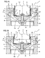
- the gas pressure regulator 1 comprises a central body 2 in which a first, gas inlet pipe 3 and a second, gas outlet pipe 4 are fitted ( Figures 1A and 1B do not show the part where the pipes are fitted in the central body).
- FIGS 1A and 1B illustrate only part of the central body 2 limited to the relevant central portion.
- the central body 2 comprises a first half-part 21 and a second half-part 22 which are connected to each other in sealed manner.
- the central body 2 has an internal cavity 24 for connecting the pipes 3 and 4.
- the regulator 1 also comprises a shutter 5 which is slidably mounted inside the central body 2.
- the shutter 5 comprises a hollow cylindrical body 25 having a respective central axis Y.
- the hollow cylindrical body 25 of the shutter is mobile relative to the central body 2 in a direction X coinciding with the central axis Y between a position B, illustrated in Figure 1B , in which a gas passage section 6 is fully open, and a position A, illustrated in Figure 1A , in which the gas passage section 6 is closed.
- the gas flows in the central body 2 substantially in a direction X parallel with the central axis Y of the hollow cylindrical body 25 of the shutter 5; in effect, the gas from the inlet pipe 3 flows through the region inside the hollow cylindrical body 25 of the shutter.
- the pressure regulator 1 also comprises a silencing device 7 housed in the cavity 24 in the central body 2 and designed to reduce the noise generated by the operation of the regulator 1.
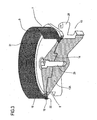
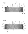
- the silencing device 7 comprises a cylindrical metal plate 9, which is perforated to allow the gas to pass through it, and an annular base 10 for supporting and stiffening the cylindrical plate 9.
- the cylindrical plate 9 and the annular base 10 are assembled in a single piece.
- the cylindrical plate 9 has on its lateral surface 30 a plurality of holes 12 sized to allow the gas to pass through it while at the same time reducing the noise created by the passage of the gas in the regulator 1.
- the holes 12 are distributed over the entire lateral surface 30 of the cylindrical plate 9.
- Figure 5 shows only some of the holes 12.
- the cylindrical plate 9 is a perforated metal plate advantageously made from a strip portion whose end edges are welded together to form an uninterrupted cylindrical lateral surface 30.
- the cylindrical plate 9 is thus welded to form an uninterrupted cylindrical lateral surface 30 which guarantees excellent stiffness of the silencing device 7 and uniform noise reduction.
- the numeral 33 denotes the weld line on the cylindrical plate 9 where the end edges of the of the strip of plate are welded to form the cylindrical plate 9.
- the cylindrical plate 9 thus obtained is economical since the steps in the process for its production are quick and easy for an operator to perform, even manually.
- cylindrical plate 9 and the annular base 10 are assembled in such a way as to form a single piece.
- the cylindrical plate 9 and the annular base 10 are welded to each other.
- the uninterrupted cylindrical plate 9 has considerable radial stiffness and the annular base 10 further stiffens the plate 9.
- the silencing device 7 thus obtained can resist high gas speeds.
- the cylindrical plate 9 has a central axis K, an upper circumferential edge 31 and a lower circumferential edge 32.
- the annular base 10 has an L-shaped section comprising a short side 35 and a long side 36.
- the cylindrical plate 9 is preferably welded to the short side 35 of the L-shaped section in the vicinity of its lower circumferential edge 32.
- the long side 36 of the L-shaped section of the annular base 10 projects radially towards the central axis K of the cylindrical plate 9.
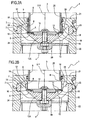
- the pressure regulator 1 comprises a silencing device 7 supporting element 13 located in the cavity 24 and on which the annular base 10 of the silencing device rests in the cavity 24.
- the supporting element 13 is in turn fixed to the central body 2 within the cavity 24.
- the supporting element 13 is removably fixed to the central body 2, for example by one or more screws.
- the supporting element 13 is made as a single piece with the central body 2.
- the supporting element 13 of the silencing device 7 comprises a frustoconical body 13A from which a plurality of radial arms 28 extend.
- the radial arms 28 are designed to engage in respective seats 23 formed between the half parts 21, 22.
- the regulator 1 also comprises an annular element 8 inserted in the cavity 24 of the central body 2 and resting on the supporting element 13.
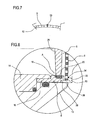
- the long side 36 of the L-shaped section of the annular base 10 forms an engagement zone 26, shown more clearly in Figure 8 , designed to make contact with a jutting portion 20 of the annular element 8.
- the jutting portion 20 of the annular element 8 is shaped to match the engagement zone 26 of the annular base 10.
- the jutting portion 20 of the annular element 8 is designed to make contact with the engagement zone 26 of the annular base 10 so as to constrain the silencing device 7 in the radial and axial directions relative to the central body 2.
- the annular element 8 is also fitted at the top of it with a gasket 16, preferably of rubber or plastic material, designed to engage the shutter 5 in sealed manner when the latter is in the closed position A.
- the gasket is fitted at the bottom of the hollow cylindrical body of the shutter and the annular element comprises a contact portion, facing the hollow cylindrical body and with which the shutter gasket comes into contact in sealed manner when the cylindrical body is in the closed position.
- the regulator 1 further comprises a disc 14 designed to make contact with an inside portion 15 of the annular element 8.
- the disc 14 is connected at the top to the supporting element 13 by a screw 29 and engages the annular element 8 to lock the angular element 8 to the supporting element 13.
- the annular element 8 and the disc 14 thus constitute means 11 for fastening the silencing device 7 to the central body 2.
- the screw 29 is inserted from above into a respective through hole in the disc 14 and screwed into the supporting element 13, whilst in Figures 1A, 1B , 2A and 2B the screw 29 is inserted from below into a respective through hole in the supporting element 13 and screwed into the disc 14.
- the regulator 1 does not comprise the disc 14 and the annular element 8 is fixed to the supporting element 13 by gluing or by an interference fit or, alternatively, by a shape fit or by screw means.
- the annular element 8 comprises an annular threaded portion designed to engage a corresponding annular threaded portion formed on the supporting element 13.
- the annular element 8 is screwed to the supporting element 13 in such a way as to provide the removable fastening of the annular element 8 to the supporting element 13.
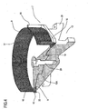
- the silencing device 7 comprises a plurality of uprights 18.
- the uprights 18 are fixed to the cylindrical plate 9, for example by welding, in order to stiffen the cylindrical plate 9.
- these uprights 18 are fixed to the lateral surface 30 of the cylindrical plate 9.
- the uprights 18 are fixed to the base 10 preferably by welding.
- the uprights 18 can be screwed to the annular base 10 or made as a single piece.
- the uprights are fixed only to the cylindrical plate.
- the uprights are fixed to the lateral inside surface of the cylindrical plate.
- the uprights 18 of the silencing device 7 illustrated in Figure 4 differ from the uprights of the silencing device 7 illustrated in Figures 2A, 2B and 6 .
- the uprights 18 of the silencing device 7 of Figure 4 have a substantially cylindrical shape and extend vertically to the upper circumferential edge 31 of the cylindrical plate 9 whilst the uprights 18 of the silencing device 7 of Figures 2A, 2B and 6 have an enlarged upper portion 18S and extend to a predetermined height of the cylindrical plate 9.
- the uprights 18 constitute elements 18 for stiffening the cylindrical plate 9 in a substantially radial direction.
- the stiffening elements 18 make it possible to strengthen the silencing device 7 in such a way that the regulator 1 can operate at very high differential pressures (generated by high gas speeds).
- the uprights 18 cover a very limited portion of the lateral surface 30 of the cylindrical plate 9 and thus, advantageously, do not significantly reduce the area of gas passage through the holes 12 in the cylindrical plate 9.
- the uprights 18 are preferably positioned at equal angular intervals so as to stiffen the cylindrical plate 9 uniformly.
- the description set out above thus defines a gas pressure regulator 1 equipped with a silencing device 7 which can operate reliably with gas flowing at high speeds and with gas carrying dirt and/or debris and which is also inexpensive to make.
- the silencing device 7 is also light and compact at the same time.
- the regulator 1 proposed herein therefore advantageously has a reduced weight and limited size.
- the method comprises the steps of:
- the step of fastening the silencing device 7 to the inside of the central body 2 comprises the following steps:
- the proposed method allows the performance of known pressure regulators to be improved at considerably reduced costs.
- the proposed method offers a simple and low-cost solution to improve the reliability of a regulator.
- Improved performance can be achieved by simply substituting the existing silencing device with a silencing device capable of operating reliably even with gas flowing at high speed and sized to suit the actual dimensions of the housing.
Landscapes
- Engineering & Computer Science (AREA)
- General Engineering & Computer Science (AREA)
- Mechanical Engineering (AREA)
- Control Of Fluid Pressure (AREA)
- Exhaust Silencers (AREA)
- Details Of Valves (AREA)
- Sampling And Sample Adjustment (AREA)
Claims (12)
- Gasdruckregler (1), umfassend:- einen zentralen Körper (2), aufweisend eine erste Gaszuführungsleitung (3) und eine zweite Gasableitungsleitung (4);- einen Verschluss (5), der mindestens zum Teil im zentralen Körper (2) untergebracht und beweglich ist, um die Öffnung eines Abschnitts (6) für den Durchlass des Gases zwischen einer Position (B), in welcher der Abschnitt (6) vollständig geöffnet ist, und einer Position (A), in welcher der Abschnitt (6) geschlossen ist, anzupassen;- eine Dämpfungsvorrichtung (7), die im zentralen Körper (2) am Durchlassabschnitt (6) liegt, zum Verringern des Geräusches, das durch den Durchlass des Gases verursacht wird;- Mittel (11) zum Befestigen der Dämpfungsvorrichtung (7) am zentralen Körper (2), wobei die Dämpfungsvorrichtung (7) Folgendes umfasst:- eine zylindrische, perforierte Platte (9) zum Gestatten des Durchlasses des Gases;- eine ringförmige Basis (10) zum Tragen und Versteifen der zylindrischen Platte (9) und aufweisend einen Bereich (26) zum Eingreifen in die Mittel (11) zum Befestigen der Dämpfungsvorrichtung (7) am zentralen Körper (2), wobei die zylindrische Platte (9) und die ringförmige Basis (10) einstückig zusammengebaut sind, wobei der Regler (1) dadurch gekennzeichnet ist, dass die Befestigungsmittel (11) ein ringförmiges Element (8) umfassen, aufweisend einen vorspringenden Teil (20), wobei der vorspringende Teil (20) so gestaltet ist, dass er mit dem Eingriffsbereich (26) der ringförmigen Basis (10) zusammenpasst, um in den Eingriffsbereich (26) einzugreifen und die Dämpfungsvorrichtung (7) am zentralen Körper (2) festzuhalten, und dadurch, dass das ringförmige Element (8) eine Dichtung (16) trägt, mit der der Verschluss (5) in der geschlossenen Position (A) abdichtend in Eingriff steht.
- Druckregler nach Anspruch 1, dadurch gekennzeichnet, dass der Verschluss (5) eine Dichtung trägt und das ringförmige Element (8) einen Kontaktteil umfasst, mit dem die Dichtung des Verschlusses (5) abdichtend in Eingriff steht, wenn dieser in der geschlossenen Position (A) ist.
- Druckregler nach einem der Ansprüche 1 bis 2, dadurch gekennzeichnet, dass die zylindrische Platte (9) mit der Basis (10) verschweißt ist, um das eine einzige Stück zu bilden.
- Druckregler nach einem der Ansprüche 1 bis 3, dadurch gekennzeichnet, dass sich die zylindrische Platte (9) kreisförmig ohne Unterbrechungen erstreckt.
- Druckregler nach einem der Ansprüche 1 bis 4, dadurch gekennzeichnet, dass er Elemente (18) zum Versteifen der zylindrischen Platte (9) umfasst.
- Druckregler nach Anspruch 5, dadurch gekennzeichnet, dass die Versteifungselemente (18) mit der ringförmigen Basis (10) verbunden sind.
- Druckregler nach Anspruch 5 oder 6, dadurch gekennzeichnet, dass sich die Versteifungselemente (18) außerhalb der zylindrischen Platte (9) in eine Richtung erstrecken, die im Wesentlichen parallel zu einer Zentralachse (K) der zylindrischen Platte (9) ist.
- Druckregler nach einem der Ansprüche 1 bis 7, dadurch gekennzeichnet, dass er ein Trägerelement (13) der Dämpfungsvorrichtung (7) umfasst, das im zentralen Körper (2) liegt und dazu konzipiert ist, die Dämpfungsvorrichtung (7) und das ringförmige Element (8) zu tragen, und dass das ringförmige Element (8) einen Gewindeteil umfasst, der dazu konzipiert ist, in das Trägerelement (13) einzugreifen, um das ringförmige Element (8) am Trägerelement (13) zu befestigen.
- Druckregler nach einem der Ansprüche 1 bis 8, dadurch gekennzeichnet, dass er Folgendes umfasst:- ein Trägerelement (13) der Dämpfungsvorrichtung (7), das im zentralen Körper (2) liegt und dazu konzipiert ist, die Dämpfungsvorrichtung (7) und das ringförmige Element (8) zu tragen, wobei die Befestigungsmittel (11) ferner eine Scheibe (14) umfassen, die am Trägerelement (13) anbringbar ist und dazu konzipiert ist, mindestens in einen Teil (15) des ringförmigen Elements (8) einzugreifen.
- Druckregler nach Anspruch 9, dadurch gekennzeichnet, dass die Scheibe (14) durch Schraubenmittel (29) am Trägerelement (13) befestigt ist, um das ringförmige Element (8) am Trägerelement (13) zu fixieren.
- Verfahren zur Verbesserung der Leistung eines Gasdruckreglers, umfassend:- einen zentralen Körper, aufweisend eine erste Gaszuführungsleitung und eine zweite Gasableitungsleitung;- einen Verschluss, der mindestens zum Teil im zentralen Körper untergebracht ist;- eine vorhandene Dämpfungsvorrichtung, die im zentralen Körper liegt, zum Verringern des Geräusches, das durch den Durchlass des Gases verursacht wird; wobei das Verfahren dadurch gekennzeichnet ist, dass es die folgenden Schritte umfasst:Entfernen der vorhandenen Dämpfungsvorrichtung;- Bereitstellen einer Dämpfungsvorrichtung (7) zum Ersetzen der vorhandenen Dämpfungsvorrichtung, umfassend: eine zylindrische, perforierte Platte (9) zum Gestatten des Durchlasses des Gases und eine ringförmige Basis (10) zum Tragen und Versteifen der zylindrischen Platte (9) und aufweisend einen Bereich (26) zum Eingreifen in die Mittel (11) zum Befestigen der Dämpfungsvorrichtung (7) am zentralen Körper, wobei die zylindrische Platte (9) und die ringförmige Basis (10) einstückig zusammengebaut sind;- Befestigen der Dämpfungsvorrichtung (7) an der Innenseite des zentralen Körpers (2) mithilfe von Befestigungsmitteln (11), umfassend ein ringförmiges Element (8), aufweisend einen vorspringenden Teil (20), der so gestaltet ist, dass er mit dem Eingriffsbereich (26) der ringförmigen Basis (10) zusammenpasst, um in den Eingriffsbereich (26) einzugreifen und die Dämpfungsvorrichtung(7) am zentralen Körper (2) festzuhalten, wobei das ringförmige Element (8) eine Dichtung (16) trägt, mit der der Verschluss (5) in der geschlossenen Position (A) abdichtend in Eingriff steht.
- Verfahren nach Anspruch 11, dadurch gekennzeichnet, dass der Schritt des Befestigens der Dämpfungsvorrichtung (7) an der Innenseite des zentralen Körpers die folgenden Schritte umfasst:- Bereitstellen von Befestigungsmitteln (11), umfassend ein ringförmiges Element (8), aufweisend einen vorspringenden Teil (20), der so gestaltet ist, dass er mit dem Eingriffsbereich (26) der ringförmigen Basis (10) zusammenpasst;- Einfügen der Dämpfungsvorrichtung (7) in den zentralen Körper;- Einfügen des ringförmigen Elements (8) in den zentralen Körper auf solch eine Art und Weise, dass es in den Eingriffsbereich (26) der ringförmigen Basis (10) eingreift;- Befestigen des ringförmigen Elements (8) am zentralen Körper.
Applications Claiming Priority (2)
| Application Number | Priority Date | Filing Date | Title |
|---|---|---|---|
| ITBO2010A000063A IT1397828B1 (it) | 2010-02-04 | 2010-02-04 | Regolatore di pressione per gas |
| PCT/IB2011/050314 WO2011095911A1 (en) | 2010-02-04 | 2011-01-25 | Gas pressure regulator |
Publications (2)
| Publication Number | Publication Date |
|---|---|
| EP2531759A1 EP2531759A1 (de) | 2012-12-12 |
| EP2531759B1 true EP2531759B1 (de) | 2015-11-04 |
Family
ID=42677237
Family Applications (1)
| Application Number | Title | Priority Date | Filing Date |
|---|---|---|---|
| EP11706009.5A Active EP2531759B1 (de) | 2010-02-04 | 2011-01-25 | Gasdruckregler |
Country Status (9)
| Country | Link |
|---|---|
| US (1) | US8671983B2 (de) |
| EP (1) | EP2531759B1 (de) |
| JP (1) | JP2013519146A (de) |
| CN (1) | CN102884351B (de) |
| BR (1) | BR112012018574B8 (de) |
| CA (1) | CA2784719C (de) |
| IT (1) | IT1397828B1 (de) |
| RU (1) | RU2560085C2 (de) |
| WO (1) | WO2011095911A1 (de) |
Families Citing this family (2)
| Publication number | Priority date | Publication date | Assignee | Title |
|---|---|---|---|---|
| CN103363296B (zh) * | 2012-03-28 | 2016-03-02 | 中联煤层气有限责任公司 | 一种煤层气选井装置 |
| DE102015016902A1 (de) * | 2015-12-29 | 2017-06-29 | Samson Aktiengesellschaft | Ventilkäfig zum Aufnehmen eines Ventilglieds und Verfahren zum Betätigen eines Stellventils mit einem Ventilkäfig und einem Ventilglied |
Family Cites Families (24)
| Publication number | Priority date | Publication date | Assignee | Title |
|---|---|---|---|---|
| SU478158A1 (ru) * | 1970-12-07 | 1975-07-25 | Предприятие П/Я Г-4534 | Регул тор давлени газа |
| US3821968A (en) * | 1973-01-26 | 1974-07-02 | Acf Ind Inc | Control valve structure having double ports |
| US4041982A (en) * | 1976-01-09 | 1977-08-16 | Kieley & Mueller, Inc. | Double wall plug control valve |
| EP0035073B1 (de) * | 1980-02-28 | 1984-06-13 | BBC Aktiengesellschaft Brown, Boveri & Cie. | Ventil mit einer Einrichtung zur Dämpfung von durch das Arbeitsmedium selbsterregten akustischen Schwingungen |
| US4402485A (en) * | 1981-06-11 | 1983-09-06 | Fisher Controls Company, Inc. | Eccentrically nested tube gas line silencer |
| US4617963A (en) * | 1983-06-23 | 1986-10-21 | Mcgraw-Edison Company | Control valve with anticavitation trim |
| US4558844A (en) * | 1985-04-11 | 1985-12-17 | Appliance Valves Corporation | Direct acting valve assembly |
| US4766932A (en) * | 1987-05-14 | 1988-08-30 | Westinghouse Electric Corp. | Steam control valve |
| US4860993A (en) * | 1988-01-14 | 1989-08-29 | Teledyne Industries, Inc. | Valve design to reduce cavitation and noise |
| US5018703A (en) * | 1988-01-14 | 1991-05-28 | Teledyne Industries, Inc. | Valve design to reduce cavitation and noise |
| US4834133A (en) * | 1988-09-28 | 1989-05-30 | Westinghouse Electric Corp. | Control valve |
| US4938450A (en) * | 1989-05-31 | 1990-07-03 | Target Rock Corporation | Programmable pressure reducing apparatus for throttling fluids under high pressure |
| US5236014A (en) * | 1992-06-01 | 1993-08-17 | Fisher Controls International, Inc. | Trim for ANSI class V shut off of valves |
| DE69422713D1 (de) * | 1993-06-28 | 2000-02-24 | Lanworth Asia Ltd | Hilfsventil |
| JP3359430B2 (ja) * | 1994-09-20 | 2002-12-24 | 株式会社山武 | 弁装置 |
| US5772178A (en) * | 1995-12-22 | 1998-06-30 | Rotatrol Ag | Rotary noise attenuating valve |
| JP2004028195A (ja) * | 2002-06-25 | 2004-01-29 | Toshiba Corp | 蒸気弁 |
| DE20312048U1 (de) * | 2003-07-30 | 2003-12-18 | Südmo Holding GmbH | Schalldämpfer für Stellventile |
| US7448409B2 (en) * | 2005-03-17 | 2008-11-11 | Fisher Controls International Llc | Fluid flow control device having a throttling element seal |
| ITBO20050197A1 (it) * | 2005-03-25 | 2006-09-26 | Omt Off Mecc Tartarini | Regolatore di pressione per gas e relativo metodo di montaggio e smontaggio |
| US7802592B2 (en) * | 2006-04-18 | 2010-09-28 | Fisher Controls International, Llc | Fluid pressure reduction devices |
| ITBO20060400A1 (it) * | 2006-05-24 | 2007-11-25 | Omt Off Mecc Tartarini | Regolatore di pressione per gas perfezionato. |
| US8740179B2 (en) * | 2007-04-18 | 2014-06-03 | Fisher Controls International, Llc | Two-piece trim for use with fluid regulators |
| JP2009209976A (ja) * | 2008-02-29 | 2009-09-17 | Osaka Gas Co Ltd | サイレンサおよびこれを備える圧力制御装置 |
-
2010
- 2010-02-04 IT ITBO2010A000063A patent/IT1397828B1/it active
-
2011
- 2011-01-21 US US13/010,861 patent/US8671983B2/en active Active
- 2011-01-25 BR BR112012018574A patent/BR112012018574B8/pt active IP Right Grant
- 2011-01-25 CA CA2784719A patent/CA2784719C/en active Active
- 2011-01-25 JP JP2012551710A patent/JP2013519146A/ja active Pending
- 2011-01-25 RU RU2012127622/06A patent/RU2560085C2/ru active
- 2011-01-25 CN CN201180008381.2A patent/CN102884351B/zh active Active
- 2011-01-25 WO PCT/IB2011/050314 patent/WO2011095911A1/en not_active Ceased
- 2011-01-25 EP EP11706009.5A patent/EP2531759B1/de active Active
Also Published As
| Publication number | Publication date |
|---|---|
| WO2011095911A1 (en) | 2011-08-11 |
| JP2013519146A (ja) | 2013-05-23 |
| BR112012018574A2 (pt) | 2016-04-05 |
| CN102884351A (zh) | 2013-01-16 |
| EP2531759A1 (de) | 2012-12-12 |
| CN102884351B (zh) | 2014-03-26 |
| BR112012018574B1 (pt) | 2020-12-01 |
| RU2560085C2 (ru) | 2015-08-20 |
| CA2784719C (en) | 2017-10-17 |
| ITBO20100063A1 (it) | 2011-08-05 |
| US20110186140A1 (en) | 2011-08-04 |
| BR112012018574B8 (pt) | 2022-07-12 |
| IT1397828B1 (it) | 2013-02-04 |
| US8671983B2 (en) | 2014-03-18 |
| RU2012127622A (ru) | 2014-03-10 |
| CA2784719A1 (en) | 2011-08-11 |
Similar Documents
| Publication | Publication Date | Title |
|---|---|---|
| EP2531759B1 (de) | Gasdruckregler | |
| US20130062273A1 (en) | Enhanced Filter Support Basket | |
| RU2012122829A (ru) | Способ и устройство для обработки уплотнительной поверхности запорной арматуры | |
| KR20120027147A (ko) | 도관 내부에 회전가능한 플랩퍼 밸브를 설치하는 방법 | |
| JP2016070464A (ja) | 弁装置 | |
| CN1990967B (zh) | 垃圾处理装置的飞溅防护件 | |
| CN202123305U (zh) | 仿形切割机 | |
| JPWO2016120961A1 (ja) | 不断流工法 | |
| EP3214337B1 (de) | Stossdämpfer | |
| CN201565746U (zh) | 自动环焊机自定心夹具 | |
| JP4494225B2 (ja) | 不断水制水体設置装置 | |
| JP5367473B2 (ja) | 工具ホルダ | |
| JP4536045B2 (ja) | 封止構造 | |
| JP2016020701A (ja) | 緩衝器 | |
| JP2019070445A (ja) | 弁装置 | |
| KR20170141041A (ko) | 배관용 필터 | |
| JP4714506B2 (ja) | 被削材のビビリ及び撓み抑制装置 | |
| JP2002098287A (ja) | 分岐開口形成装置およびこれを用いる分岐開口形成工法 | |
| JP2010007627A (ja) | ストレーナ | |
| CN205533110U (zh) | 一种空压机用一体式中心托架 | |
| CN104002122A (zh) | 汽车机油冷却器水管接头的防位置偏差的压装机构 | |
| CN207642546U (zh) | 带有调节装置双工位焊接夹持设备 | |
| KR20110047147A (ko) | 가스 터빈 배기 지주 개조 | |
| CN107186267B (zh) | 一种滤清器壳体加工设备 | |
| CN200968378Y (zh) | 气缸密封装置 |
Legal Events
| Date | Code | Title | Description |
|---|---|---|---|
| PUAI | Public reference made under article 153(3) epc to a published international application that has entered the european phase |
Free format text: ORIGINAL CODE: 0009012 |
|
| 17P | Request for examination filed |
Effective date: 20120731 |
|
| AK | Designated contracting states |
Kind code of ref document: A1 Designated state(s): AL AT BE BG CH CY CZ DE DK EE ES FI FR GB GR HR HU IE IS IT LI LT LU LV MC MK MT NL NO PL PT RO RS SE SI SK SM TR |
|
| DAX | Request for extension of the european patent (deleted) | ||
| 17Q | First examination report despatched |
Effective date: 20130604 |
|
| GRAP | Despatch of communication of intention to grant a patent |
Free format text: ORIGINAL CODE: EPIDOSNIGR1 |
|
| INTG | Intention to grant announced |
Effective date: 20150520 |
|
| GRAS | Grant fee paid |
Free format text: ORIGINAL CODE: EPIDOSNIGR3 |
|
| GRAA | (expected) grant |
Free format text: ORIGINAL CODE: 0009210 |
|
| AK | Designated contracting states |
Kind code of ref document: B1 Designated state(s): AL AT BE BG CH CY CZ DE DK EE ES FI FR GB GR HR HU IE IS IT LI LT LU LV MC MK MT NL NO PL PT RO RS SE SI SK SM TR |
|
| REG | Reference to a national code |
Ref country code: GB Ref legal event code: FG4D |
|
| REG | Reference to a national code |
Ref country code: CH Ref legal event code: EP |
|
| REG | Reference to a national code |
Ref country code: AT Ref legal event code: REF Ref document number: 759448 Country of ref document: AT Kind code of ref document: T Effective date: 20151115 |
|
| REG | Reference to a national code |
Ref country code: IE Ref legal event code: FG4D |
|
| REG | Reference to a national code |
Ref country code: DE Ref legal event code: R096 Ref document number: 602011021129 Country of ref document: DE |
|
| REG | Reference to a national code |
Ref country code: FR Ref legal event code: PLFP Year of fee payment: 6 |
|
| REG | Reference to a national code |
Ref country code: NL Ref legal event code: MP Effective date: 20151104 |
|
| REG | Reference to a national code |
Ref country code: LT Ref legal event code: MG4D |
|
| REG | Reference to a national code |
Ref country code: AT Ref legal event code: MK05 Ref document number: 759448 Country of ref document: AT Kind code of ref document: T Effective date: 20151104 |
|
| PG25 | Lapsed in a contracting state [announced via postgrant information from national office to epo] |
Ref country code: NL Free format text: LAPSE BECAUSE OF FAILURE TO SUBMIT A TRANSLATION OF THE DESCRIPTION OR TO PAY THE FEE WITHIN THE PRESCRIBED TIME-LIMIT Effective date: 20151104 Ref country code: IS Free format text: LAPSE BECAUSE OF FAILURE TO SUBMIT A TRANSLATION OF THE DESCRIPTION OR TO PAY THE FEE WITHIN THE PRESCRIBED TIME-LIMIT Effective date: 20160304 Ref country code: ES Free format text: LAPSE BECAUSE OF FAILURE TO SUBMIT A TRANSLATION OF THE DESCRIPTION OR TO PAY THE FEE WITHIN THE PRESCRIBED TIME-LIMIT Effective date: 20151104 Ref country code: HR Free format text: LAPSE BECAUSE OF FAILURE TO SUBMIT A TRANSLATION OF THE DESCRIPTION OR TO PAY THE FEE WITHIN THE PRESCRIBED TIME-LIMIT Effective date: 20151104 Ref country code: LT Free format text: LAPSE BECAUSE OF FAILURE TO SUBMIT A TRANSLATION OF THE DESCRIPTION OR TO PAY THE FEE WITHIN THE PRESCRIBED TIME-LIMIT Effective date: 20151104 Ref country code: NO Free format text: LAPSE BECAUSE OF FAILURE TO SUBMIT A TRANSLATION OF THE DESCRIPTION OR TO PAY THE FEE WITHIN THE PRESCRIBED TIME-LIMIT Effective date: 20160204 |
|
| PG25 | Lapsed in a contracting state [announced via postgrant information from national office to epo] |
Ref country code: AT Free format text: LAPSE BECAUSE OF FAILURE TO SUBMIT A TRANSLATION OF THE DESCRIPTION OR TO PAY THE FEE WITHIN THE PRESCRIBED TIME-LIMIT Effective date: 20151104 Ref country code: PT Free format text: LAPSE BECAUSE OF FAILURE TO SUBMIT A TRANSLATION OF THE DESCRIPTION OR TO PAY THE FEE WITHIN THE PRESCRIBED TIME-LIMIT Effective date: 20160304 Ref country code: LV Free format text: LAPSE BECAUSE OF FAILURE TO SUBMIT A TRANSLATION OF THE DESCRIPTION OR TO PAY THE FEE WITHIN THE PRESCRIBED TIME-LIMIT Effective date: 20151104 Ref country code: PL Free format text: LAPSE BECAUSE OF FAILURE TO SUBMIT A TRANSLATION OF THE DESCRIPTION OR TO PAY THE FEE WITHIN THE PRESCRIBED TIME-LIMIT Effective date: 20151104 Ref country code: GR Free format text: LAPSE BECAUSE OF FAILURE TO SUBMIT A TRANSLATION OF THE DESCRIPTION OR TO PAY THE FEE WITHIN THE PRESCRIBED TIME-LIMIT Effective date: 20160205 Ref country code: BE Free format text: LAPSE BECAUSE OF NON-PAYMENT OF DUE FEES Effective date: 20160131 Ref country code: RS Free format text: LAPSE BECAUSE OF FAILURE TO SUBMIT A TRANSLATION OF THE DESCRIPTION OR TO PAY THE FEE WITHIN THE PRESCRIBED TIME-LIMIT Effective date: 20151104 Ref country code: FI Free format text: LAPSE BECAUSE OF FAILURE TO SUBMIT A TRANSLATION OF THE DESCRIPTION OR TO PAY THE FEE WITHIN THE PRESCRIBED TIME-LIMIT Effective date: 20151104 Ref country code: SE Free format text: LAPSE BECAUSE OF FAILURE TO SUBMIT A TRANSLATION OF THE DESCRIPTION OR TO PAY THE FEE WITHIN THE PRESCRIBED TIME-LIMIT Effective date: 20151104 |
|
| PG25 | Lapsed in a contracting state [announced via postgrant information from national office to epo] |
Ref country code: CZ Free format text: LAPSE BECAUSE OF FAILURE TO SUBMIT A TRANSLATION OF THE DESCRIPTION OR TO PAY THE FEE WITHIN THE PRESCRIBED TIME-LIMIT Effective date: 20151104 |
|
| REG | Reference to a national code |
Ref country code: DE Ref legal event code: R097 Ref document number: 602011021129 Country of ref document: DE |
|
| PG25 | Lapsed in a contracting state [announced via postgrant information from national office to epo] |
Ref country code: SM Free format text: LAPSE BECAUSE OF FAILURE TO SUBMIT A TRANSLATION OF THE DESCRIPTION OR TO PAY THE FEE WITHIN THE PRESCRIBED TIME-LIMIT Effective date: 20151104 Ref country code: LU Free format text: LAPSE BECAUSE OF FAILURE TO SUBMIT A TRANSLATION OF THE DESCRIPTION OR TO PAY THE FEE WITHIN THE PRESCRIBED TIME-LIMIT Effective date: 20160125 Ref country code: RO Free format text: LAPSE BECAUSE OF FAILURE TO SUBMIT A TRANSLATION OF THE DESCRIPTION OR TO PAY THE FEE WITHIN THE PRESCRIBED TIME-LIMIT Effective date: 20151104 Ref country code: EE Free format text: LAPSE BECAUSE OF FAILURE TO SUBMIT A TRANSLATION OF THE DESCRIPTION OR TO PAY THE FEE WITHIN THE PRESCRIBED TIME-LIMIT Effective date: 20151104 Ref country code: SK Free format text: LAPSE BECAUSE OF FAILURE TO SUBMIT A TRANSLATION OF THE DESCRIPTION OR TO PAY THE FEE WITHIN THE PRESCRIBED TIME-LIMIT Effective date: 20151104 Ref country code: DK Free format text: LAPSE BECAUSE OF FAILURE TO SUBMIT A TRANSLATION OF THE DESCRIPTION OR TO PAY THE FEE WITHIN THE PRESCRIBED TIME-LIMIT Effective date: 20151104 |
|
| REG | Reference to a national code |
Ref country code: CH Ref legal event code: PL |
|
| PLBE | No opposition filed within time limit |
Free format text: ORIGINAL CODE: 0009261 |
|
| STAA | Information on the status of an ep patent application or granted ep patent |
Free format text: STATUS: NO OPPOSITION FILED WITHIN TIME LIMIT |
|
| PG25 | Lapsed in a contracting state [announced via postgrant information from national office to epo] |
Ref country code: MC Free format text: LAPSE BECAUSE OF FAILURE TO SUBMIT A TRANSLATION OF THE DESCRIPTION OR TO PAY THE FEE WITHIN THE PRESCRIBED TIME-LIMIT Effective date: 20151104 |
|
| 26N | No opposition filed |
Effective date: 20160805 |
|
| PG25 | Lapsed in a contracting state [announced via postgrant information from national office to epo] |
Ref country code: CH Free format text: LAPSE BECAUSE OF NON-PAYMENT OF DUE FEES Effective date: 20160131 Ref country code: LI Free format text: LAPSE BECAUSE OF NON-PAYMENT OF DUE FEES Effective date: 20160131 |
|
| REG | Reference to a national code |
Ref country code: IE Ref legal event code: MM4A |
|
| PG25 | Lapsed in a contracting state [announced via postgrant information from national office to epo] |
Ref country code: SI Free format text: LAPSE BECAUSE OF FAILURE TO SUBMIT A TRANSLATION OF THE DESCRIPTION OR TO PAY THE FEE WITHIN THE PRESCRIBED TIME-LIMIT Effective date: 20151104 |
|
| PG25 | Lapsed in a contracting state [announced via postgrant information from national office to epo] |
Ref country code: BE Free format text: LAPSE BECAUSE OF FAILURE TO SUBMIT A TRANSLATION OF THE DESCRIPTION OR TO PAY THE FEE WITHIN THE PRESCRIBED TIME-LIMIT Effective date: 20151104 |
|
| REG | Reference to a national code |
Ref country code: FR Ref legal event code: PLFP Year of fee payment: 7 |
|
| PG25 | Lapsed in a contracting state [announced via postgrant information from national office to epo] |
Ref country code: IE Free format text: LAPSE BECAUSE OF NON-PAYMENT OF DUE FEES Effective date: 20160125 |
|
| PG25 | Lapsed in a contracting state [announced via postgrant information from national office to epo] |
Ref country code: MT Free format text: LAPSE BECAUSE OF FAILURE TO SUBMIT A TRANSLATION OF THE DESCRIPTION OR TO PAY THE FEE WITHIN THE PRESCRIBED TIME-LIMIT Effective date: 20151104 |
|
| REG | Reference to a national code |
Ref country code: FR Ref legal event code: PLFP Year of fee payment: 8 |
|
| PG25 | Lapsed in a contracting state [announced via postgrant information from national office to epo] |
Ref country code: HU Free format text: LAPSE BECAUSE OF FAILURE TO SUBMIT A TRANSLATION OF THE DESCRIPTION OR TO PAY THE FEE WITHIN THE PRESCRIBED TIME-LIMIT; INVALID AB INITIO Effective date: 20110125 Ref country code: CY Free format text: LAPSE BECAUSE OF FAILURE TO SUBMIT A TRANSLATION OF THE DESCRIPTION OR TO PAY THE FEE WITHIN THE PRESCRIBED TIME-LIMIT Effective date: 20151104 |
|
| PG25 | Lapsed in a contracting state [announced via postgrant information from national office to epo] |
Ref country code: MK Free format text: LAPSE BECAUSE OF FAILURE TO SUBMIT A TRANSLATION OF THE DESCRIPTION OR TO PAY THE FEE WITHIN THE PRESCRIBED TIME-LIMIT Effective date: 20151104 Ref country code: TR Free format text: LAPSE BECAUSE OF FAILURE TO SUBMIT A TRANSLATION OF THE DESCRIPTION OR TO PAY THE FEE WITHIN THE PRESCRIBED TIME-LIMIT Effective date: 20151104 Ref country code: MT Free format text: LAPSE BECAUSE OF FAILURE TO SUBMIT A TRANSLATION OF THE DESCRIPTION OR TO PAY THE FEE WITHIN THE PRESCRIBED TIME-LIMIT Effective date: 20160131 |
|
| PG25 | Lapsed in a contracting state [announced via postgrant information from national office to epo] |
Ref country code: BG Free format text: LAPSE BECAUSE OF FAILURE TO SUBMIT A TRANSLATION OF THE DESCRIPTION OR TO PAY THE FEE WITHIN THE PRESCRIBED TIME-LIMIT Effective date: 20151104 |
|
| PG25 | Lapsed in a contracting state [announced via postgrant information from national office to epo] |
Ref country code: AL Free format text: LAPSE BECAUSE OF FAILURE TO SUBMIT A TRANSLATION OF THE DESCRIPTION OR TO PAY THE FEE WITHIN THE PRESCRIBED TIME-LIMIT Effective date: 20151104 |
|
| REG | Reference to a national code |
Ref country code: DE Ref legal event code: R082 Ref document number: 602011021129 Country of ref document: DE Representative=s name: MANITZ FINSTERWALD PATENT- UND RECHTSANWALTSPA, DE Ref country code: DE Ref legal event code: R081 Ref document number: 602011021129 Country of ref document: DE Owner name: EMERSON PROCESS MANAGEMENT S.R.L., IT Free format text: FORMER OWNER: O.M.T. OFFICINA MECCANICA TARTARINI S.R.L., CASTEL MAGGIORE, IT |
|
| REG | Reference to a national code |
Ref country code: GB Ref legal event code: 732E Free format text: REGISTERED BETWEEN 20201105 AND 20201111 |
|
| P01 | Opt-out of the competence of the unified patent court (upc) registered |
Effective date: 20230526 |
|
| PGFP | Annual fee paid to national office [announced via postgrant information from national office to epo] |
Ref country code: DE Payment date: 20241218 Year of fee payment: 15 |
|
| PGFP | Annual fee paid to national office [announced via postgrant information from national office to epo] |
Ref country code: IT Payment date: 20250107 Year of fee payment: 15 |
|
| PGFP | Annual fee paid to national office [announced via postgrant information from national office to epo] |
Ref country code: GB Payment date: 20251220 Year of fee payment: 16 |
|
| PGFP | Annual fee paid to national office [announced via postgrant information from national office to epo] |
Ref country code: FR Payment date: 20251218 Year of fee payment: 16 |