EP2531748B1 - Autonome hydraulische drehmoment-modulierungsvorrichtung - Google Patents
Autonome hydraulische drehmoment-modulierungsvorrichtung Download PDFInfo
- Publication number
- EP2531748B1 EP2531748B1 EP11740262.8A EP11740262A EP2531748B1 EP 2531748 B1 EP2531748 B1 EP 2531748B1 EP 11740262 A EP11740262 A EP 11740262A EP 2531748 B1 EP2531748 B1 EP 2531748B1
- Authority
- EP
- European Patent Office
- Prior art keywords
- clutch
- case
- differential
- piston
- coupling device
- Prior art date
- Legal status (The legal status is an assumption and is not a legal conclusion. Google has not performed a legal analysis and makes no representation as to the accuracy of the status listed.)
- Active
Links
Images
Classifications
-
- F—MECHANICAL ENGINEERING; LIGHTING; HEATING; WEAPONS; BLASTING
- F16—ENGINEERING ELEMENTS AND UNITS; GENERAL MEASURES FOR PRODUCING AND MAINTAINING EFFECTIVE FUNCTIONING OF MACHINES OR INSTALLATIONS; THERMAL INSULATION IN GENERAL
- F16H—GEARING
- F16H48/00—Differential gearings
- F16H48/06—Differential gearings with gears having orbital motion
- F16H48/08—Differential gearings with gears having orbital motion comprising bevel gears
-
- F—MECHANICAL ENGINEERING; LIGHTING; HEATING; WEAPONS; BLASTING
- F16—ENGINEERING ELEMENTS AND UNITS; GENERAL MEASURES FOR PRODUCING AND MAINTAINING EFFECTIVE FUNCTIONING OF MACHINES OR INSTALLATIONS; THERMAL INSULATION IN GENERAL
- F16H—GEARING
- F16H48/00—Differential gearings
- F16H48/20—Arrangements for suppressing or influencing the differential action, e.g. locking devices
- F16H48/22—Arrangements for suppressing or influencing the differential action, e.g. locking devices using friction clutches or brakes
-
- F—MECHANICAL ENGINEERING; LIGHTING; HEATING; WEAPONS; BLASTING
- F16—ENGINEERING ELEMENTS AND UNITS; GENERAL MEASURES FOR PRODUCING AND MAINTAINING EFFECTIVE FUNCTIONING OF MACHINES OR INSTALLATIONS; THERMAL INSULATION IN GENERAL
- F16H—GEARING
- F16H48/00—Differential gearings
- F16H48/20—Arrangements for suppressing or influencing the differential action, e.g. locking devices
- F16H48/30—Arrangements for suppressing or influencing the differential action, e.g. locking devices using externally-actuatable means
- F16H48/32—Arrangements for suppressing or influencing the differential action, e.g. locking devices using externally-actuatable means using fluid pressure actuators
Definitions
- the present invention relates to clutch units, and more particularly to a self-contained clutch device that can be attached between two axle shafts.
- Clutch devices are often used to modulate torque between two shafts, such as two axle shafts in a vehicle.
- hydraulic pressure is applied to a piston in the device, which in turn applies pressure to the clutch to allow torque transfer between the two shafts.
- the axle housing, axle bearings, and other gear drive interfaces tend to have complex configurations to accommodate these forces. This complexity may also add to the size of the unit, which is undesirable given the trend toward smaller units with greater functionality.
- a torque-coupling device comprising a hydraulically actuated friction clutch pack and a gerotor pump provided for generating hydraulic pressure actuating the friction clutch pack.
- the gerotor pump is selectively actuated by a device external to the gerotor pump and the friction clutch pack.
- the externally driven gerotor pump may be further provided with torque-multiplication gearing, and/or an electronic controller to modulate the actuation of the pump in order to provide flexible control of the hydraulic pressure generated by the gerotor pump.
- EP 1 574 737 A1 there is disclosed a system as it is defined in the pre-characterizing portion of claim 1.
- the present invention is a system having a differential disposed in a bore of an axle housing, a first shaft and a second shaft coupled to the differential, as it is defined in claim 1.
- One embodiment of the invention is a torque modulating coupling device having a case and a clutch and a piston disposed in the case.
- the coupling device operatively links a first shaft and a second shaft in an axle system.
- the piston selectively applies force to the clutch in response to hydraulic pressure to engage the clutch.
- the device also includes a keyed feature adapted to couple with a corresponding keyed feature associated with at least one of the shafts in the system when the clutch engages.
- the coupling device may be formed with two cases that form an enclosure for the clutch and the piston, trapping the piston forces between the cases.
- the two-case embodiment allows the device to also act as an axle housing cover, allowing the axle system to have a smaller profile.
- the device is formed with a single case designed to bolt directly to an axle housing cover, trapping piston forces between the case and the cover.
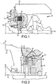
- FIG. 1 is a cross sectional view of a torque modulating coupling device 10 according to one embodiment of the invention.
- the coupling device 10 may be attached with a bolt 12 or other fastener to an axle housing 14, wherein the coupling device 10 is provided between the axle housing 14 and a differential 16 having a first, output shaft 40 and a second, output shaft 41, disposed in a bore 18 of the axle housing 14.
- the coupling device 10 can be attached between other structures in a drive system, such as an output shaft, a second axle shaft, two axle housings, etc. instead of between an axle housing 14 and a differential 16 without departing from the scope of the invention.
- the coupling device 10 includes a first case 20 and a second case 22.
- the first and second cases 20, 22 together form an enclosure for components in the device 10.
- the components which will be described in greater detail below, include a clutch 24 and a piston 26 that selectively applies force to the clutch 24.
- the coupling device 10 includes one or more keyed features that engage with corresponding keyed features on the structure(s) that the coupling device 10 is attached to.
- the keyed features on the coupling device 10 include an outer diameter spline coupling 32 that engages with an outer spline portion of the differential 16 and an inner diameter spline coupling 36 that engages with an outer spline portion of the output shaft 40.
- the spline couplings 32, 36 in this embodiment are formed as part of the clutch 24.
- the keyed features may be modified and/or be incorporated in another part of the coupling device 10 to engage securely with corresponding keyed features of the other structure.
- the coupling device 10 is self-contained and can be easily bolted on to a drive system without requiring complex modifications of any of the drive system components.
- the coupling device 10 itself, and particularly any keyed features that provide an engagement function similar to the spline couplings 32, 36, may be easily modified to accommodate the specific drive configuration that the coupling device 10 will be attached to.
- the forces applied by the piston 26 are captured between the first and second cases 20, 22.
- the piston 26 can generate massive forces, and if these forces are not contained, the size and cost of other components in the system, such as the axle bearings, may increase to accommodate these forces.
- the coupling device 10 can accommodate these large forces without requiring any changes to components outside the coupling device 10.
- the coupling device 10 shown in Figure 1 makes the overall system more compact because it acts as part of the axle housing 14 and also supports a bearing in the differential 16. If a customer wished to offer the system without the coupling device 10, it would need to replace the coupling device 10 with a solid cover to support the differential.
- integrating the coupling device 10 with the axle housing 14 as shown in Figure 1 allows the coupling device 10 to act as a cover as well, providing multiple functions in a compact design.
- hydraulic pressure is applied to the piston 26 by routing hydraulic fluid into the coupling device 10, which applies a force to a ring 30 that in turn applies a force to the piston 26.
- the piston 26 applies a force to the clutch 24, which engages the keyed features (e.g., the spline couplings 32, 36 with the corresponding keyed features in the differential 16 and output shaft 40) to couple the coupling device 10 to the differential 16.
- This engagement and the force from the clutch 24 generate a torque linking the differential 16 with the output shaft 40, causing the differential 16 and output shaft 40 to approach the same rotational speed and modulating torque between the output shaft 40 and the second output shaft 41 based on the amount of clutch force applied.
- the coupling device 10 may directly link the differential 16 to an output shaft or other structure without departing from the scope of the invention.
- Figure 2 illustrates the coupling device 10 according to another embodiment of the invention.
- This embodiment does not have the second case 22 shown in the previous embodiment, and as a result the components of the coupling device 10 are enclosed between the first case 20 and a solid cover 42 attached to the axle housing 14.
- the coupling device 10 according to this embodiment is still a complete, self-contained unit and can simply be attached to the cover, 42, axle housing 14 or other drive system component without requiring complex modification of the drive component itself.
- the complex modification of the drive component itself is bolted onto the cover 42 rather than acting as a cover itself.
- this embodiment may result in a less compact profile than the embodiment in Figure 1 .
- it also may allow a customer to offer a system both with and without the coupling device 10 with minimal or no modification of the drive system.
- the other components of the coupling device 10 are similar to those in Figure 1 .
- the coupling device 10 couples the output shaft 40 to the differential 16 via the outer diameter spline coupling 32, which couples the differential 16 to the plates in the clutch 24, and the inner diameter spline coupling 36, which couples the clutch 24 to a corresponding portion that is in turn splined to the output shaft 40.
Landscapes
- Engineering & Computer Science (AREA)
- General Engineering & Computer Science (AREA)
- Mechanical Engineering (AREA)
- Retarders (AREA)
- Hydraulic Clutches, Magnetic Clutches, Fluid Clutches, And Fluid Joints (AREA)
- Arrangement And Mounting Of Devices That Control Transmission Of Motive Force (AREA)
- Arrangement Of Transmissions (AREA)
Claims (6)
- System mit einem Differential (16), das in einer Bohrung (18) eines Achsgehäuses (14) angeordnet ist, einer ersten Welle (40) und einer zweiten Welle (41), die mit dem Differential (16) gekoppelt sind, umfassend:
eine Kopplungsvorrichtung (10), die zwischen dem Achsgehäuse (14) und dem Differential (16) vorgesehen ist und das Drehmoment zwischen der ersten und der zweiten Welle moduliert, dadurch gekennzeichnet, dass die Kopplungsvorrichtung Folgendes umfasst:ein Gehäuse mit einem ersten Abschnitt (20) und einem zweiten Abschnitt (22; 42), wobei das Gehäuse eine Umhüllung bildet, die konfiguriert ist, um Kolbenkräfte zwischen dem ersten Abschnitt und dem zweiten Abschnitt einzufangen,eine Kupplung (24), die in dem Gehäuse angeordnet ist,einen Kolben (26), der in dem Gehäuse angeordnet ist, wobei der Kolben als Reaktion auf den Hydraulikdruck in dem Gehäuse selektiv Kraft auf die Kupplung (24) ausübt, um die Kupplung in Eingriff zu bringen, undeine Außendurchmesser-Keilwellenkupplung (32) und eine Innendurchmesser-Keilwellenkupplung (36), wobei die Außendurchmesser-Keilwellenkupplung (32) und die Innendurchmesser-Keilwellenkupplung (36) dazu ausgelegt sind, das Differential (16) mit mindestens einer der ersten Welle (40) und der zweiten Welle (41) zu koppeln, wenn die Kupplung (24) eingreift. - System nach Anspruch 1, wobei die Umhüllung die Kupplung (24) und den Kolben (26) umschließt.
- System nach Anspruch 2, wobei mindestens eines von dem ersten Gehäuse (20) und dem zweiten Gehäuse (22) als eine Abdeckung 42 fungiert, die an dem Achsgehäuse 14 für das System angebracht ist.
- System nach Anspruch 1, ferner umfassend eine Abdeckung (42), die an dem Achsgehäuse (14) befestigt ist, und
wobei das Gehäuse konfiguriert ist, um an der Abdeckung (42) befestigt zu werden, um die Kupplung (24) und den Kolben (26) zwischen dem Gehäuse und der Abdeckung (42) zu umschließen. - System nach Anspruch 1, wobei die Kopplungsvorrichtung (10) ferner mindestens eines aus einem Ring (30) und einer Vielzahl von Stiften (46) einschließt, die hydraulisch betätigt werden, um selektiv Kraft auf den Kolben (26) auszuüben.
- System nach Anspruch 1, wobei
die Außendurchmesser-Keilwellenkupplung (32) in einen Außenkeilwellenabschnitt des Differentials (16) eingreift; und
die Innendurchmesser-Keilwellenkupplung (36) in einen Keilwellenabschnitt des Differentials (16) eingreift.
Applications Claiming Priority (2)
| Application Number | Priority Date | Filing Date | Title |
|---|---|---|---|
| US30056410P | 2010-02-02 | 2010-02-02 | |
| PCT/US2011/023361 WO2011097237A1 (en) | 2010-02-02 | 2011-02-01 | Self-contained hydraulic torque modulating device |
Publications (3)
| Publication Number | Publication Date |
|---|---|
| EP2531748A1 EP2531748A1 (de) | 2012-12-12 |
| EP2531748A4 EP2531748A4 (de) | 2013-08-07 |
| EP2531748B1 true EP2531748B1 (de) | 2021-01-06 |
Family
ID=44342147
Family Applications (1)
| Application Number | Title | Priority Date | Filing Date |
|---|---|---|---|
| EP11740262.8A Active EP2531748B1 (de) | 2010-02-02 | 2011-02-01 | Autonome hydraulische drehmoment-modulierungsvorrichtung |
Country Status (6)
| Country | Link |
|---|---|
| US (1) | US8550952B2 (de) |
| EP (1) | EP2531748B1 (de) |
| KR (1) | KR20120135242A (de) |
| CN (1) | CN102812269B (de) |
| RU (1) | RU2012137232A (de) |
| WO (1) | WO2011097237A1 (de) |
Families Citing this family (1)
| Publication number | Priority date | Publication date | Assignee | Title |
|---|---|---|---|---|
| KR102681100B1 (ko) * | 2022-11-23 | 2024-07-04 | 현대트랜시스 주식회사 | 차량용 디스커넥터장치 |
Family Cites Families (18)
| Publication number | Priority date | Publication date | Assignee | Title |
|---|---|---|---|---|
| US4679463A (en) * | 1984-08-31 | 1987-07-14 | Nissan Motor Co., Ltd. | Limited slip differential |
| DE3819702A1 (de) | 1988-06-09 | 1989-12-14 | Porsche Ag | Hydraulisch betaetigte doppelkupplung fuer ein kraftfahrzeug |
| EP0395247B1 (de) | 1989-04-27 | 1993-09-08 | Fuji Jukogyo Kabushiki Kaisha | Kraftübertragungssystem für ein vierradgetriebenes Kraftfahrzeug |
| IT1250886B (it) * | 1991-12-20 | 1995-04-21 | Fiat Ricerche | Sistema per il controllo della ripartizione della coppia motrice tra le ruote di uno stesso assale di un veicolo. |
| US5582557A (en) * | 1995-06-07 | 1996-12-10 | Titan Wheel International, Inc. | Hydraulically-operable locking differential with in-line piston means |
| US6076646A (en) | 1997-11-07 | 2000-06-20 | New Venture Gear, Inc. | Self-contained hydraulic coupling |
| AT407077B (de) * | 1997-11-25 | 2000-12-27 | Steyr Daimler Puch Ag | Antriebseinheit mit drehzahldifferenzabhängiger hydraulischer kupplung für den antriebsstrang von fahrzeugen |
| US6161643A (en) | 1997-12-10 | 2000-12-19 | Daimlerchrysler Corporation | System of controlling torque transfer in a motor vehicle and related method |
| AU766974B2 (en) * | 1999-12-28 | 2003-10-30 | Hyundai Motor Company | Power train for automatic transmissions |
| US6536560B1 (en) * | 2001-11-27 | 2003-03-25 | Dana Corporation | Single braking assembly for a drive axle |
| US20050026732A1 (en) * | 2003-08-01 | 2005-02-03 | Krisher James A. | Limited slip differential assembly |
| US7051857B2 (en) * | 2004-03-08 | 2006-05-30 | Eaton Corporation | Coupling device and improved method of controlling torque transmission |
| AT8015U1 (de) * | 2005-02-25 | 2005-12-15 | Magna Steyr Fahrzeugtechnik Ag | Differentialgetriebeeinheit für kraftfahrzeuge mit aktiver steuerung der antriebskraftverteilung |
| US7318511B2 (en) * | 2005-06-27 | 2008-01-15 | Eaton Corporation | Coupling device independent of differential speed |
| US7452301B2 (en) * | 2006-02-15 | 2008-11-18 | Dana Automotive Systems Group, Llc | Externally actuated torque coupling for drivetrain |
| US20080103009A1 (en) | 2006-10-31 | 2008-05-01 | Jungho Park | Self-contained torque-coupling assembly |
| CA2680733A1 (en) * | 2007-03-19 | 2008-09-25 | Eaton Corporation | Idle-able power transfer unit |
| US8596436B2 (en) * | 2008-12-16 | 2013-12-03 | Eaton Corporation | Idle-able auxiliary drive system |
-
2011
- 2011-02-01 EP EP11740262.8A patent/EP2531748B1/de active Active
- 2011-02-01 WO PCT/US2011/023361 patent/WO2011097237A1/en not_active Ceased
- 2011-02-01 CN CN201180008274.XA patent/CN102812269B/zh active Active
- 2011-02-01 KR KR1020127022610A patent/KR20120135242A/ko not_active Withdrawn
- 2011-02-01 US US13/019,006 patent/US8550952B2/en active Active
- 2011-02-01 RU RU2012137232/11A patent/RU2012137232A/ru not_active Application Discontinuation
Non-Patent Citations (1)
| Title |
|---|
| None * |
Also Published As
| Publication number | Publication date |
|---|---|
| US8550952B2 (en) | 2013-10-08 |
| RU2012137232A (ru) | 2014-03-10 |
| EP2531748A1 (de) | 2012-12-12 |
| WO2011097237A1 (en) | 2011-08-11 |
| CN102812269A (zh) | 2012-12-05 |
| EP2531748A4 (de) | 2013-08-07 |
| KR20120135242A (ko) | 2012-12-12 |
| CN102812269B (zh) | 2015-10-14 |
| US20110190088A1 (en) | 2011-08-04 |
Similar Documents
| Publication | Publication Date | Title |
|---|---|---|
| US7247117B2 (en) | Drive axle with a work drive that can be driven by the electric motor of a traction drive | |
| EP2373902B1 (de) | Antriebsmechanismus für ein fahrzeug | |
| EP3133310B1 (de) | Doppelkupplungsvorrichtung | |
| US9328779B2 (en) | Clutch housing and assembly | |
| EP1837544A1 (de) | Abtriebswelle mit axial beweglichem Lager | |
| CN103423441B (zh) | 离合器装置和双速变速箱 | |
| EP2820326B1 (de) | Mehrgängige antriebseinheit | |
| US10723215B2 (en) | Clutch device for a hybrid drive system | |
| EP2531748B1 (de) | Autonome hydraulische drehmoment-modulierungsvorrichtung | |
| US20180339586A1 (en) | Planetary-stage automatic transmission having an alternative auxiliary power take-off assembly | |
| US7361117B2 (en) | Differential limiter | |
| EP3449144B1 (de) | Verfahren zur steuerung einer kupplungsanordnung in einem getriebe | |
| US9103389B2 (en) | Transmission brake hub | |
| EP4283151A1 (de) | Betätigungssystem für eine mehrkammerkupplung mit kraftverstärkung für zapfwelle | |
| WO1999041099A2 (en) | Power take-off unit having integral pump mounting flange | |
| EP2297482B1 (de) | Kompaktes getriebe mit einem planetenradsatz | |
| JP4162559B2 (ja) | 作業車の作業用伝動構造 | |
| EP2871388B1 (de) | Getriebeantriebseinheit für Industriemaschinen | |
| CN107001008A (zh) | 液压装置 | |
| EP2956327B1 (de) | Kombinierte zapfwellen- und synchronisierereinheit | |
| CN107848412A (zh) | 用于动力输出装置的离合器组 | |
| JP2015140863A (ja) | 自動変速機用の動力伝達用クラッチの遠心キャンセル構造 |
Legal Events
| Date | Code | Title | Description |
|---|---|---|---|
| PUAI | Public reference made under article 153(3) epc to a published international application that has entered the european phase |
Free format text: ORIGINAL CODE: 0009012 |
|
| 17P | Request for examination filed |
Effective date: 20120809 |
|
| AK | Designated contracting states |
Kind code of ref document: A1 Designated state(s): AL AT BE BG CH CY CZ DE DK EE ES FI FR GB GR HR HU IE IS IT LI LT LU LV MC MK MT NL NO PL PT RO RS SE SI SK SM TR |
|
| DAX | Request for extension of the european patent (deleted) | ||
| A4 | Supplementary search report drawn up and despatched |
Effective date: 20130710 |
|
| RIC1 | Information provided on ipc code assigned before grant |
Ipc: F16H 48/22 20060101AFI20130704BHEP Ipc: F16H 48/32 20120101ALI20130704BHEP Ipc: F16H 48/08 20060101ALI20130704BHEP |
|
| 17Q | First examination report despatched |
Effective date: 20150907 |
|
| STAA | Information on the status of an ep patent application or granted ep patent |
Free format text: STATUS: EXAMINATION IS IN PROGRESS |
|
| GRAP | Despatch of communication of intention to grant a patent |
Free format text: ORIGINAL CODE: EPIDOSNIGR1 |
|
| STAA | Information on the status of an ep patent application or granted ep patent |
Free format text: STATUS: GRANT OF PATENT IS INTENDED |
|
| INTG | Intention to grant announced |
Effective date: 20200318 |
|
| GRAJ | Information related to disapproval of communication of intention to grant by the applicant or resumption of examination proceedings by the epo deleted |
Free format text: ORIGINAL CODE: EPIDOSDIGR1 |
|
| STAA | Information on the status of an ep patent application or granted ep patent |
Free format text: STATUS: EXAMINATION IS IN PROGRESS |
|
| INTC | Intention to grant announced (deleted) | ||
| RAP1 | Party data changed (applicant data changed or rights of an application transferred) |
Owner name: EATON CORPORATION |
|
| GRAP | Despatch of communication of intention to grant a patent |
Free format text: ORIGINAL CODE: EPIDOSNIGR1 |
|
| STAA | Information on the status of an ep patent application or granted ep patent |
Free format text: STATUS: GRANT OF PATENT IS INTENDED |
|
| RAP1 | Party data changed (applicant data changed or rights of an application transferred) |
Owner name: EATON CORPORATION |
|
| INTG | Intention to grant announced |
Effective date: 20200722 |
|
| RAP1 | Party data changed (applicant data changed or rights of an application transferred) |
Owner name: EATON INTELLIGENT POWER LIMITED |
|
| GRAS | Grant fee paid |
Free format text: ORIGINAL CODE: EPIDOSNIGR3 |
|
| GRAA | (expected) grant |
Free format text: ORIGINAL CODE: 0009210 |
|
| STAA | Information on the status of an ep patent application or granted ep patent |
Free format text: STATUS: THE PATENT HAS BEEN GRANTED |
|
| AK | Designated contracting states |
Kind code of ref document: B1 Designated state(s): AL AT BE BG CH CY CZ DE DK EE ES FI FR GB GR HR HU IE IS IT LI LT LU LV MC MK MT NL NO PL PT RO RS SE SI SK SM TR |
|
| REG | Reference to a national code |
Ref country code: GB Ref legal event code: FG4D |
|
| REG | Reference to a national code |
Ref country code: AT Ref legal event code: REF Ref document number: 1352723 Country of ref document: AT Kind code of ref document: T Effective date: 20210115 Ref country code: CH Ref legal event code: EP |
|
| REG | Reference to a national code |
Ref country code: DE Ref legal event code: R096 Ref document number: 602011069872 Country of ref document: DE |
|
| REG | Reference to a national code |
Ref country code: IE Ref legal event code: FG4D |
|
| REG | Reference to a national code |
Ref country code: NL Ref legal event code: MP Effective date: 20210106 |
|
| REG | Reference to a national code |
Ref country code: AT Ref legal event code: MK05 Ref document number: 1352723 Country of ref document: AT Kind code of ref document: T Effective date: 20210106 |
|
| REG | Reference to a national code |
Ref country code: LT Ref legal event code: MG9D |
|
| PG25 | Lapsed in a contracting state [announced via postgrant information from national office to epo] |
Ref country code: PT Free format text: LAPSE BECAUSE OF FAILURE TO SUBMIT A TRANSLATION OF THE DESCRIPTION OR TO PAY THE FEE WITHIN THE PRESCRIBED TIME-LIMIT Effective date: 20210506 Ref country code: LT Free format text: LAPSE BECAUSE OF FAILURE TO SUBMIT A TRANSLATION OF THE DESCRIPTION OR TO PAY THE FEE WITHIN THE PRESCRIBED TIME-LIMIT Effective date: 20210106 Ref country code: GR Free format text: LAPSE BECAUSE OF FAILURE TO SUBMIT A TRANSLATION OF THE DESCRIPTION OR TO PAY THE FEE WITHIN THE PRESCRIBED TIME-LIMIT Effective date: 20210407 Ref country code: FI Free format text: LAPSE BECAUSE OF FAILURE TO SUBMIT A TRANSLATION OF THE DESCRIPTION OR TO PAY THE FEE WITHIN THE PRESCRIBED TIME-LIMIT Effective date: 20210106 Ref country code: HR Free format text: LAPSE BECAUSE OF FAILURE TO SUBMIT A TRANSLATION OF THE DESCRIPTION OR TO PAY THE FEE WITHIN THE PRESCRIBED TIME-LIMIT Effective date: 20210106 Ref country code: BG Free format text: LAPSE BECAUSE OF FAILURE TO SUBMIT A TRANSLATION OF THE DESCRIPTION OR TO PAY THE FEE WITHIN THE PRESCRIBED TIME-LIMIT Effective date: 20210406 Ref country code: NO Free format text: LAPSE BECAUSE OF FAILURE TO SUBMIT A TRANSLATION OF THE DESCRIPTION OR TO PAY THE FEE WITHIN THE PRESCRIBED TIME-LIMIT Effective date: 20210406 Ref country code: NL Free format text: LAPSE BECAUSE OF FAILURE TO SUBMIT A TRANSLATION OF THE DESCRIPTION OR TO PAY THE FEE WITHIN THE PRESCRIBED TIME-LIMIT Effective date: 20210106 |
|
| PG25 | Lapsed in a contracting state [announced via postgrant information from national office to epo] |
Ref country code: SE Free format text: LAPSE BECAUSE OF FAILURE TO SUBMIT A TRANSLATION OF THE DESCRIPTION OR TO PAY THE FEE WITHIN THE PRESCRIBED TIME-LIMIT Effective date: 20210106 Ref country code: AT Free format text: LAPSE BECAUSE OF FAILURE TO SUBMIT A TRANSLATION OF THE DESCRIPTION OR TO PAY THE FEE WITHIN THE PRESCRIBED TIME-LIMIT Effective date: 20210106 Ref country code: PL Free format text: LAPSE BECAUSE OF FAILURE TO SUBMIT A TRANSLATION OF THE DESCRIPTION OR TO PAY THE FEE WITHIN THE PRESCRIBED TIME-LIMIT Effective date: 20210106 Ref country code: LV Free format text: LAPSE BECAUSE OF FAILURE TO SUBMIT A TRANSLATION OF THE DESCRIPTION OR TO PAY THE FEE WITHIN THE PRESCRIBED TIME-LIMIT Effective date: 20210106 |
|
| PG25 | Lapsed in a contracting state [announced via postgrant information from national office to epo] |
Ref country code: IS Free format text: LAPSE BECAUSE OF FAILURE TO SUBMIT A TRANSLATION OF THE DESCRIPTION OR TO PAY THE FEE WITHIN THE PRESCRIBED TIME-LIMIT Effective date: 20210506 |
|
| REG | Reference to a national code |
Ref country code: DE Ref legal event code: R097 Ref document number: 602011069872 Country of ref document: DE |
|
| REG | Reference to a national code |
Ref country code: BE Ref legal event code: MM Effective date: 20210228 |
|
| PG25 | Lapsed in a contracting state [announced via postgrant information from national office to epo] |
Ref country code: EE Free format text: LAPSE BECAUSE OF FAILURE TO SUBMIT A TRANSLATION OF THE DESCRIPTION OR TO PAY THE FEE WITHIN THE PRESCRIBED TIME-LIMIT Effective date: 20210106 Ref country code: CZ Free format text: LAPSE BECAUSE OF FAILURE TO SUBMIT A TRANSLATION OF THE DESCRIPTION OR TO PAY THE FEE WITHIN THE PRESCRIBED TIME-LIMIT Effective date: 20210106 Ref country code: LU Free format text: LAPSE BECAUSE OF NON-PAYMENT OF DUE FEES Effective date: 20210201 Ref country code: LI Free format text: LAPSE BECAUSE OF NON-PAYMENT OF DUE FEES Effective date: 20210228 Ref country code: MC Free format text: LAPSE BECAUSE OF FAILURE TO SUBMIT A TRANSLATION OF THE DESCRIPTION OR TO PAY THE FEE WITHIN THE PRESCRIBED TIME-LIMIT Effective date: 20210106 Ref country code: SM Free format text: LAPSE BECAUSE OF FAILURE TO SUBMIT A TRANSLATION OF THE DESCRIPTION OR TO PAY THE FEE WITHIN THE PRESCRIBED TIME-LIMIT Effective date: 20210106 Ref country code: CH Free format text: LAPSE BECAUSE OF NON-PAYMENT OF DUE FEES Effective date: 20210228 |
|
| PLBE | No opposition filed within time limit |
Free format text: ORIGINAL CODE: 0009261 |
|
| STAA | Information on the status of an ep patent application or granted ep patent |
Free format text: STATUS: NO OPPOSITION FILED WITHIN TIME LIMIT |
|
| PG25 | Lapsed in a contracting state [announced via postgrant information from national office to epo] |
Ref country code: DK Free format text: LAPSE BECAUSE OF FAILURE TO SUBMIT A TRANSLATION OF THE DESCRIPTION OR TO PAY THE FEE WITHIN THE PRESCRIBED TIME-LIMIT Effective date: 20210106 Ref country code: ES Free format text: LAPSE BECAUSE OF FAILURE TO SUBMIT A TRANSLATION OF THE DESCRIPTION OR TO PAY THE FEE WITHIN THE PRESCRIBED TIME-LIMIT Effective date: 20210106 Ref country code: SK Free format text: LAPSE BECAUSE OF FAILURE TO SUBMIT A TRANSLATION OF THE DESCRIPTION OR TO PAY THE FEE WITHIN THE PRESCRIBED TIME-LIMIT Effective date: 20210106 Ref country code: RO Free format text: LAPSE BECAUSE OF FAILURE TO SUBMIT A TRANSLATION OF THE DESCRIPTION OR TO PAY THE FEE WITHIN THE PRESCRIBED TIME-LIMIT Effective date: 20210106 |
|
| 26N | No opposition filed |
Effective date: 20211007 |
|
| GBPC | Gb: european patent ceased through non-payment of renewal fee |
Effective date: 20210406 |
|
| PG25 | Lapsed in a contracting state [announced via postgrant information from national office to epo] |
Ref country code: AL Free format text: LAPSE BECAUSE OF FAILURE TO SUBMIT A TRANSLATION OF THE DESCRIPTION OR TO PAY THE FEE WITHIN THE PRESCRIBED TIME-LIMIT Effective date: 20210106 Ref country code: FR Free format text: LAPSE BECAUSE OF NON-PAYMENT OF DUE FEES Effective date: 20210306 Ref country code: GB Free format text: LAPSE BECAUSE OF NON-PAYMENT OF DUE FEES Effective date: 20210406 Ref country code: IE Free format text: LAPSE BECAUSE OF NON-PAYMENT OF DUE FEES Effective date: 20210201 |
|
| PG25 | Lapsed in a contracting state [announced via postgrant information from national office to epo] |
Ref country code: SI Free format text: LAPSE BECAUSE OF FAILURE TO SUBMIT A TRANSLATION OF THE DESCRIPTION OR TO PAY THE FEE WITHIN THE PRESCRIBED TIME-LIMIT Effective date: 20210106 |
|
| PG25 | Lapsed in a contracting state [announced via postgrant information from national office to epo] |
Ref country code: IT Free format text: LAPSE BECAUSE OF FAILURE TO SUBMIT A TRANSLATION OF THE DESCRIPTION OR TO PAY THE FEE WITHIN THE PRESCRIBED TIME-LIMIT Effective date: 20210106 |
|
| PG25 | Lapsed in a contracting state [announced via postgrant information from national office to epo] |
Ref country code: IS Free format text: LAPSE BECAUSE OF FAILURE TO SUBMIT A TRANSLATION OF THE DESCRIPTION OR TO PAY THE FEE WITHIN THE PRESCRIBED TIME-LIMIT Effective date: 20210506 |
|
| PG25 | Lapsed in a contracting state [announced via postgrant information from national office to epo] |
Ref country code: BE Free format text: LAPSE BECAUSE OF NON-PAYMENT OF DUE FEES Effective date: 20210228 |
|
| PG25 | Lapsed in a contracting state [announced via postgrant information from national office to epo] |
Ref country code: RS Free format text: LAPSE BECAUSE OF FAILURE TO SUBMIT A TRANSLATION OF THE DESCRIPTION OR TO PAY THE FEE WITHIN THE PRESCRIBED TIME-LIMIT Effective date: 20210106 Ref country code: HU Free format text: LAPSE BECAUSE OF FAILURE TO SUBMIT A TRANSLATION OF THE DESCRIPTION OR TO PAY THE FEE WITHIN THE PRESCRIBED TIME-LIMIT; INVALID AB INITIO Effective date: 20110201 Ref country code: CY Free format text: LAPSE BECAUSE OF FAILURE TO SUBMIT A TRANSLATION OF THE DESCRIPTION OR TO PAY THE FEE WITHIN THE PRESCRIBED TIME-LIMIT Effective date: 20210106 |
|
| P01 | Opt-out of the competence of the unified patent court (upc) registered |
Effective date: 20230521 |
|
| PG25 | Lapsed in a contracting state [announced via postgrant information from national office to epo] |
Ref country code: MK Free format text: LAPSE BECAUSE OF FAILURE TO SUBMIT A TRANSLATION OF THE DESCRIPTION OR TO PAY THE FEE WITHIN THE PRESCRIBED TIME-LIMIT Effective date: 20210106 |
|
| PG25 | Lapsed in a contracting state [announced via postgrant information from national office to epo] |
Ref country code: MT Free format text: LAPSE BECAUSE OF FAILURE TO SUBMIT A TRANSLATION OF THE DESCRIPTION OR TO PAY THE FEE WITHIN THE PRESCRIBED TIME-LIMIT Effective date: 20210106 |
|
| PGFP | Annual fee paid to national office [announced via postgrant information from national office to epo] |
Ref country code: DE Payment date: 20250122 Year of fee payment: 15 |
|
| PG25 | Lapsed in a contracting state [announced via postgrant information from national office to epo] |
Ref country code: TR Free format text: LAPSE BECAUSE OF FAILURE TO SUBMIT A TRANSLATION OF THE DESCRIPTION OR TO PAY THE FEE WITHIN THE PRESCRIBED TIME-LIMIT Effective date: 20210106 |