EP2531456B1 - Roller cleaning device - Google Patents
Roller cleaning device Download PDFInfo
- Publication number
- EP2531456B1 EP2531456B1 EP11705032.8A EP11705032A EP2531456B1 EP 2531456 B1 EP2531456 B1 EP 2531456B1 EP 11705032 A EP11705032 A EP 11705032A EP 2531456 B1 EP2531456 B1 EP 2531456B1
- Authority
- EP
- European Patent Office
- Prior art keywords
- roller
- predisposed
- cleaning element
- cleaning
- contact
- Prior art date
- Legal status (The legal status is an assumption and is not a legal conclusion. Google has not performed a legal analysis and makes no representation as to the accuracy of the status listed.)
- Active
Links
Images

Classifications
-
- C—CHEMISTRY; METALLURGY
- C03—GLASS; MINERAL OR SLAG WOOL
- C03B—MANUFACTURE, SHAPING, OR SUPPLEMENTARY PROCESSES
- C03B35/00—Transporting of glass products during their manufacture, e.g. hot glass lenses, prisms
- C03B35/14—Transporting hot glass sheets or ribbons, e.g. by heat-resistant conveyor belts or bands
- C03B35/16—Transporting hot glass sheets or ribbons, e.g. by heat-resistant conveyor belts or bands by roller conveyors
- C03B35/168—Means for cleaning the rollers
-
- B—PERFORMING OPERATIONS; TRANSPORTING
- B08—CLEANING
- B08B—CLEANING IN GENERAL; PREVENTION OF FOULING IN GENERAL
- B08B1/00—Cleaning by methods involving the use of tools
- B08B1/30—Cleaning by methods involving the use of tools by movement of cleaning members over a surface
-
- B—PERFORMING OPERATIONS; TRANSPORTING
- B65—CONVEYING; PACKING; STORING; HANDLING THIN OR FILAMENTARY MATERIAL
- B65G—TRANSPORT OR STORAGE DEVICES, e.g. CONVEYORS FOR LOADING OR TIPPING, SHOP CONVEYOR SYSTEMS OR PNEUMATIC TUBE CONVEYORS
- B65G45/00—Lubricating, cleaning, or clearing devices
- B65G45/10—Cleaning devices
-
- F—MECHANICAL ENGINEERING; LIGHTING; HEATING; WEAPONS; BLASTING
- F27—FURNACES; KILNS; OVENS; RETORTS
- F27B—FURNACES, KILNS, OVENS OR RETORTS IN GENERAL; OPEN SINTERING OR LIKE APPARATUS
- F27B9/00—Furnaces through which the charge is moved mechanically, e.g. of tunnel type; Similar furnaces in which the charge moves by gravity
- F27B9/14—Furnaces through which the charge is moved mechanically, e.g. of tunnel type; Similar furnaces in which the charge moves by gravity characterised by the path of the charge during treatment; characterised by the means by which the charge is moved during treatment
- F27B9/20—Furnaces through which the charge is moved mechanically, e.g. of tunnel type; Similar furnaces in which the charge moves by gravity characterised by the path of the charge during treatment; characterised by the means by which the charge is moved during treatment the charge moving in a substantially straight path
- F27B9/24—Furnaces through which the charge is moved mechanically, e.g. of tunnel type; Similar furnaces in which the charge moves by gravity characterised by the path of the charge during treatment; characterised by the means by which the charge is moved during treatment the charge moving in a substantially straight path being carried by a conveyor
- F27B9/2407—Furnaces through which the charge is moved mechanically, e.g. of tunnel type; Similar furnaces in which the charge moves by gravity characterised by the path of the charge during treatment; characterised by the means by which the charge is moved during treatment the charge moving in a substantially straight path being carried by a conveyor the conveyor being constituted by rollers (roller hearth furnace)
-
- F—MECHANICAL ENGINEERING; LIGHTING; HEATING; WEAPONS; BLASTING
- F27—FURNACES; KILNS; OVENS; RETORTS
- F27B—FURNACES, KILNS, OVENS OR RETORTS IN GENERAL; OPEN SINTERING OR LIKE APPARATUS
- F27B9/00—Furnaces through which the charge is moved mechanically, e.g. of tunnel type; Similar furnaces in which the charge moves by gravity
- F27B9/30—Details, accessories or equipment specially adapted for furnaces of these types
-
- F—MECHANICAL ENGINEERING; LIGHTING; HEATING; WEAPONS; BLASTING
- F27—FURNACES; KILNS; OVENS; RETORTS
- F27D—DETAILS OR ACCESSORIES OF FURNACES, KILNS, OVENS OR RETORTS, IN SO FAR AS THEY ARE OF KINDS OCCURRING IN MORE THAN ONE KIND OF FURNACE
- F27D25/00—Devices or methods for removing incrustations, e.g. slag, metal deposits, dust; Devices or methods for preventing the adherence of slag
- F27D25/001—Devices or methods for removing incrustations, e.g. slag, metal deposits, dust; Devices or methods for preventing the adherence of slag comprising breaking tools, e.g. hammers, drills, scrapers
Definitions
- the invention relates to a device for cleaning rollers, in particular for roller conveyor planes.
- Roller conveyors are widely present in many technical sectors, known also as roller planes, by means of which objects of various natures are advanced along a determined direction.
- a field in which roller planes are widely used is in kilns for heat treatment of glass sheets where the sheets are directly rested on rollers. In the production cycle, the glass sheets are transported on roller plane conveyors, in particular during the heat treatment performed inside the kilns.
- Roller plane conveyors comprise a plurality of rollers which are parallel and flanked to one another along a conveying direction. At least some of the rollers are motorised.
- a particularly relevant problem in all sectors of use is the difficulty in cleaning the rollers which make up the conveyor planes.
- the cleaning of the rollers is performed by hand by one or more operatives who have to move along the whole conveyor plane in order to reach all the rollers.
- the operation also involves a certain degree of risk, as the rollers have to be activated in rotation during the cleaning operation in order that the whole surface of the rollers can be carefully cleaned.
- the above-described drawbacks are considerably accentuated when it becomes necessary to clean a roller conveyor plane located internally of a kiln for heat treatment of glass sheets where the sheets are directly rested on the rollers. In this case, the kiln has to be turned off and cooled almost down to ambient temperature in order to enable access by the operatives.
- Document US 4,042,364 discloses an apparatus for the cleaning of conveyor rolls of a float glass furnace, comprising a carriage with a rotating brush mounted thereto, the carriage being reciprocally movable throughout the length of the working surfaces of the conveyor rolls.
- the brush can be retracted from the roll surface by means of a power cylinder.
- An aim of the present invention is to provide a device for cleaning rollers, in particular for roller conveyor planes, which enables the rollers to be cleaned easily and carefully, but without the need for any operatives to enter into contact with the actual rollers.
- the invention also exhibits the important characteristic of not requiring removal of the rollers from the kiln. It is used with the rollers still in their seatings internally of the kiln.
- the device for cleaning rollers according to the present invention is particularly suitable for cleaning rollers which form a roller conveyor plane, such as for example roller planes used in kilns for heat treatment of glass sheets where the sheets are directly rested on the roller device. It comprises at least a cleaning element 2, predisposed to enter into contact with the surface of at least a roller 100 and perform cleaning thereof. Motor means 30, 31, 32 are predisposed to activate the cleaning element 2 and slide at least along a longitudinal direction x of a roller 100.
- the motor means 30, 31, 32 are predisposed such as to activate the cleaning element 2 to move also along a first transversal direction y, perpendicular to the longitudinal direction x, between an active position, in which the cleaning element 2 is in contact with the surface of the roller 100, and an inactive position, in which the cleaning element 2 is distanced from the roller surface 100.
- the motor means 30, 31, 32 are further predisposed to activate the cleaning element 2 to move along a second transversal direction z, perpendicular to the longitudinal direction x and to the first transversal direction y.
- the motor means 30, 31, 32 enable the cleaning element to be moved above the roller 100 such that cleaning the surface of the roller is possible along the whole extension thereof.
- the cleaning of the surface of a roller 100 comprises that the cleaning element, initially located above an end portion of the roller, is made to descend from the inactive position into the active position. In the active position, the cleaning element 2 is made to slide along the longitudinal direction x on the surface of the roller 100 which is activated in rotation. The sliding velocity of the cleaning element 2 is such that each section of the roller 100 passes into contact with the cleaning element 2. After having reached the other end portion of the roller 100, the cleaning element is raised towards the inactive position and translates towards another roller 100, placing itself above an end portion thereof. From this position the cleaning element 2 descends towards the active position in which it enters into contact with the surface of the new roller 100 and begins to slide in a way that is similar to what has already been described.
- the said motor means 30, 31, 32 comprise a straight guide 30, arranged parallel to the longitudinal direction x, along which a carriage 31 is slidable, to which carriage 30 the cleaning element 2 is associated.
- the straight guide 30 is preferably provided, at end zones thereof, with rest wheels 32 destined to be arranged in contact with the surface of the roller 100 such as to enable a predetermined positioning of the straight guide 30 with respect to the roller 100.
- the motor means 30, 31, 32 further comprise a device for translating the straight guide 30 along the second transversal direction z, such as to enable the cleaning element 2 to displace from a roller to the other rollers which make up the roller plane.
- a further device can be provided to translate the straight guide 30 along the first transversal direction y, such as to displace the cleaning element between the active position and the inactive position.
- the device comprises at least two cleaning elements 2, 2a distanced from one another in a parallel direction to the longitudinal direction x and predisposed to be positioned in contact with two distinct zones of the roller 100.
- the device comprises two further cleaning elements 2b, 2c, distanced from one another in a parallel direction to the longitudinal direction x and predisposed to be positioned in contact with two distinct zones of a second roller 100a. All the cleaning elements, whether two or four in number, can be associated to a same carriage 31, such as to displace between the rollers 100 in synchrony. In the active position, the cleaning elements are arranged contemporaneously in contact with two rollers 100, 100a, which are therefore contemporaneously cleaned.
- a first pair of cleaning elements 2, 2a can advantageously be provided with characteristics of a certain type, for example the first couple can be suitable for performing a first general cleaning of the roller surfaces.
- the second pair of cleaning elements 2b, 2c can be more suitable for a more complete cleaning of the roller surface.
- the cleaning element 2 like the other cleaning elements 2a, 2b, 2c if present, comprises a support plate 3, predisposed to accommodate and retain an insert 4 destined to enter into contact with the surface of the roller 100 in order to clean it.
- the insert 4 can be made for example of an abrasive material.
- Presser means 5, preferably a helix spring, are predisposed to exert a thrusting action on the support plate 3, which presses the insert 4 into contact with the roller 100 surface. Thanks to the presence of the presser means 5, which are preferably elastic, the insert 4 is pressed elastically into contact with the surface of the roller 100. In this way the cleaning element 2 is able to remain in contact with the roller surface 100, even where there are surface irregularities which might be present on the surface of the insert 4 as well as on that of the roller 100.
- At least a linear actuator can be predisposed (not illustrated) on board the carriage 31.
- the linear actuator can be associated to the cleaning element 2, and to the other cleaning elements 2a, 2b, 2c if present, such as to translate the cleaning element 2 with respect to the carriage 31 along the first transversal direction y.
- the device according to the present invention can be provided with an aspirating device 7, 8 predisposed to remove the residues of the cleaning operation of the contact zone between the cleaning element 2 and the other cleaning elements 2a, 2b, 2c if present, and the rollers 100.
- the aspirating device comprises at least a conduit 7 which sets in communication an aspirating machine with a body 8 provided with as many aspirating mouths 81, 82, 83, 84 as there are cleaning elements.
- the device according to the present invention provides important advantages. First and foremost it guarantees careful and efficient cleaning of the rollers.
- the device is further able to function completely autonomously, without any need for an operative to participate in the cleaning operations apart from checking the device from a remote location.
- the use of several cleaning elements enables the cleaning of the rollers to be made more rapid, and, if there are inserts of different materials, enables the rollers to be cleaned particularly carefully.
- the invention further exhibits the characteristic, of crucial significance, of not requiring the removal of the rollers from the kiln. It is used with rollers in their seatings internally of the kiln.
Landscapes
- Engineering & Computer Science (AREA)
- Mechanical Engineering (AREA)
- Chemical & Material Sciences (AREA)
- General Engineering & Computer Science (AREA)
- Materials Engineering (AREA)
- Organic Chemistry (AREA)
- Cleaning In General (AREA)
- Tunnel Furnaces (AREA)
- Rolls And Other Rotary Bodies (AREA)
- Spinning Or Twisting Of Yarns (AREA)
Description
- The invention relates to a device for cleaning rollers, in particular for roller conveyor planes.
- Roller conveyors are widely present in many technical sectors, known also as roller planes, by means of which objects of various natures are advanced along a determined direction. A field in which roller planes are widely used is in kilns for heat treatment of glass sheets where the sheets are directly rested on rollers. In the production cycle, the glass sheets are transported on roller plane conveyors, in particular during the heat treatment performed inside the kilns.
- Roller plane conveyors comprise a plurality of rollers which are parallel and flanked to one another along a conveying direction. At least some of the rollers are motorised.
- A particularly relevant problem in all sectors of use is the difficulty in cleaning the rollers which make up the conveyor planes. The cleaning of the rollers is performed by hand by one or more operatives who have to move along the whole conveyor plane in order to reach all the rollers. Apart from being long and laborious, the operation also involves a certain degree of risk, as the rollers have to be activated in rotation during the cleaning operation in order that the whole surface of the rollers can be carefully cleaned. The above-described drawbacks are considerably accentuated when it becomes necessary to clean a roller conveyor plane located internally of a kiln for heat treatment of glass sheets where the sheets are directly rested on the rollers. In this case, the kiln has to be turned off and cooled almost down to ambient temperature in order to enable access by the operatives.
- Document
US 4,042,364 discloses an apparatus for the cleaning of conveyor rolls of a float glass furnace, comprising a carriage with a rotating brush mounted thereto, the carriage being reciprocally movable throughout the length of the working surfaces of the conveyor rolls. The brush can be retracted from the roll surface by means of a power cylinder. - An aim of the present invention is to provide a device for cleaning rollers, in particular for roller conveyor planes, which enables the rollers to be cleaned easily and carefully, but without the need for any operatives to enter into contact with the actual rollers.
- The invention also exhibits the important characteristic of not requiring removal of the rollers from the kiln. It is used with the rollers still in their seatings internally of the kiln.
- Further characteristics and advantages of the present invention will clearly emerge from the following nonlimiting description, of a preferred but not exclusive embodiment of the invention, as illustrated in the accompanying drawings, in which:
-
figure 1 illustrates a part of a transversal section of a roller kiln for heat treatment of glass sheets; -
figure 2 illustrates a part of a view from above offigure 1 ; -
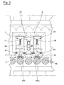
figure 3 shows, in enlarged scale, part of a section made along a perpendicular plane to the rollers. - The device for cleaning rollers according to the present invention is particularly suitable for cleaning rollers which form a roller conveyor plane, such as for example roller planes used in kilns for heat treatment of glass sheets where the sheets are directly rested on the roller device. It comprises at least a
cleaning element 2, predisposed to enter into contact with the surface of at least aroller 100 and perform cleaning thereof. Motor means 30, 31, 32 are predisposed to activate thecleaning element 2 and slide at least along a longitudinal direction x of aroller 100. - The motor means 30, 31, 32 are predisposed such as to activate the
cleaning element 2 to move also along a first transversal direction y, perpendicular to the longitudinal direction x, between an active position, in which thecleaning element 2 is in contact with the surface of theroller 100, and an inactive position, in which thecleaning element 2 is distanced from theroller surface 100. The motor means 30, 31, 32 are further predisposed to activate thecleaning element 2 to move along a second transversal direction z, perpendicular to the longitudinal direction x and to the first transversal direction y. - The motor means 30, 31, 32 enable the cleaning element to be moved above the
roller 100 such that cleaning the surface of the roller is possible along the whole extension thereof. In particular, the cleaning of the surface of aroller 100 comprises that the cleaning element, initially located above an end portion of the roller, is made to descend from the inactive position into the active position. In the active position, thecleaning element 2 is made to slide along the longitudinal direction x on the surface of theroller 100 which is activated in rotation. The sliding velocity of thecleaning element 2 is such that each section of theroller 100 passes into contact with thecleaning element 2. After having reached the other end portion of theroller 100, the cleaning element is raised towards the inactive position and translates towardsanother roller 100, placing itself above an end portion thereof. From this position thecleaning element 2 descends towards the active position in which it enters into contact with the surface of thenew roller 100 and begins to slide in a way that is similar to what has already been described. - In the preferred embodiment of the device, the said motor means 30, 31, 32 comprise a
straight guide 30, arranged parallel to the longitudinal direction x, along which acarriage 31 is slidable, to whichcarriage 30 thecleaning element 2 is associated. Thestraight guide 30 is preferably provided, at end zones thereof, withrest wheels 32 destined to be arranged in contact with the surface of theroller 100 such as to enable a predetermined positioning of thestraight guide 30 with respect to theroller 100. The motor means 30, 31, 32 further comprise a device for translating thestraight guide 30 along the second transversal direction z, such as to enable thecleaning element 2 to displace from a roller to the other rollers which make up the roller plane. A further device can be provided to translate thestraight guide 30 along the first transversal direction y, such as to displace the cleaning element between the active position and the inactive position. - According to a first embodiment, the device comprises at least two
cleaning elements roller 100. According to a second embodiment, the device comprises twofurther cleaning elements second roller 100a. All the cleaning elements, whether two or four in number, can be associated to asame carriage 31, such as to displace between therollers 100 in synchrony. In the active position, the cleaning elements are arranged contemporaneously in contact with tworollers cleaning elements cleaning elements - Preferably, the
cleaning element 2, like theother cleaning elements support plate 3, predisposed to accommodate and retain aninsert 4 destined to enter into contact with the surface of theroller 100 in order to clean it. Theinsert 4 can be made for example of an abrasive material. Presser means 5, preferably a helix spring, are predisposed to exert a thrusting action on thesupport plate 3, which presses theinsert 4 into contact with theroller 100 surface. Thanks to the presence of the presser means 5, which are preferably elastic, theinsert 4 is pressed elastically into contact with the surface of theroller 100. In this way thecleaning element 2 is able to remain in contact with theroller surface 100, even where there are surface irregularities which might be present on the surface of theinsert 4 as well as on that of theroller 100. - As an alternative solution to the translation of the
straight guide 30 along the first transversal direction y, at least a linear actuator can be predisposed (not illustrated) on board thecarriage 31. The linear actuator can be associated to thecleaning element 2, and to theother cleaning elements cleaning element 2 with respect to thecarriage 31 along the first transversal direction y. - The device according to the present invention can be provided with an
aspirating device 7, 8 predisposed to remove the residues of the cleaning operation of the contact zone between thecleaning element 2 and theother cleaning elements rollers 100. The aspirating device comprises at least a conduit 7 which sets in communication an aspirating machine with abody 8 provided with as many aspiratingmouths - The device according to the present invention provides important advantages. First and foremost it guarantees careful and efficient cleaning of the rollers. The device is further able to function completely autonomously, without any need for an operative to participate in the cleaning operations apart from checking the device from a remote location. The use of several cleaning elements enables the cleaning of the rollers to be made more rapid, and, if there are inserts of different materials, enables the rollers to be cleaned particularly carefully.
- The invention further exhibits the characteristic, of crucial significance, of not requiring the removal of the rollers from the kiln. It is used with rollers in their seatings internally of the kiln.
Claims (10)
- A roller cleaning device, in particular for roller kilns, comprising a cleaning element (2), predisposed to enter into contact with a surface of at least a roller (100) and to clean the said surface; motor means, predisposed to activate the cleaning element (2) to slide at least along a longitudinal direction (x) of the roller (100), characterized in that the motor means are predisposed to activate the cleaning element (2) to move along a first transversal direction (y), perpendicular to the longitudinal direction (x), between an active position, in which the cleaning element (2) is in contact with the surface of the roller (100), and an inactive position, in which the cleaning element (2) is removed from the surface of the roller (100, the motor means being predisposed to activate the cleaning element (2) in movement along a second transversal direction (z), perpendicular to the longitudinal direction (x) and to the first transversal direction (y).
- The device of claim 1, wherein the motor means comprise a straight guide (30) arranged parallel to the longitudinal direction (x), along which a carriage (31) slides, to which carriage (31) the cleaning element (2) is associated.
- The device of claim 2, wherein the straight guide (30) is provided at end zones thereof with rest wheels (32) destined to come into contact with the surface of the roller (100) in order to enable a predetermined positioning of the straight guide (30) with respect to the roller (100).
- The device of claim 2 or 3, wherein the motor means comprise a device for translating the straight guide (30) along the second transversal direction (z).
- The device of one of claims from 2 to 4, wherein the motor means comprise a device for translating the straight guide (30) along the first transversal direction (y).
- The device of one of claims from 2 to 4, wherein the motor means comprise at least a linear actuator associated to the carriage (31) and predisposed to translate the cleaning element (2) along the first transversal direction (y).
- The device of one of the preceding claims, wherein the cleaning element (2) comprises: a support plate (3), predisposed to receive and retain an insert (4) destined to enter into contact with the surface of the roller (100) in order to clean the roller (100); presser means (5), predisposed to exert a thrust action on the support plate (3) which presses the insert (4) into contact with the surface of the roller (100).
- The device of one of the preceding claims, comprising at least two cleaning elements (2,2a) which are reciprocally distanced in a parallel direction to the longitudinal direction (x) and predisposed to be positioned in contact with two distinct zones of the roller (100).
- The device of claim 7, comprising two further rollers (2b, 2c) which are reciprocally distanced in a parallel direction to the longitudinal direction (x) and predisposed to be positioned in contact with two distinct zones of a second roller (100a).
- The device of one of the preceding claims, comprising an aspirating device (7, 8) predisposed to remove residues of cleaning from the contact zone between the cleaning element (2) and the other cleaning elements (2a, 2b, 2c) if present, and the rollers (100).
Priority Applications (1)
| Application Number | Priority Date | Filing Date | Title |
|---|---|---|---|
| PL11705032T PL2531456T3 (en) | 2010-02-02 | 2011-01-18 | Roller cleaning device |
Applications Claiming Priority (2)
| Application Number | Priority Date | Filing Date | Title |
|---|---|---|---|
| IT000020A ITMO20100020A1 (en) | 2010-02-02 | 2010-02-02 | ROLLER CLEANING DEVICE. |
| PCT/IB2011/050204 WO2011095906A1 (en) | 2010-02-02 | 2011-01-18 | Roller cleaning device |
Publications (2)
| Publication Number | Publication Date |
|---|---|
| EP2531456A1 EP2531456A1 (en) | 2012-12-12 |
| EP2531456B1 true EP2531456B1 (en) | 2014-12-10 |
Family
ID=42732638
Family Applications (1)
| Application Number | Title | Priority Date | Filing Date |
|---|---|---|---|
| EP11705032.8A Active EP2531456B1 (en) | 2010-02-02 | 2011-01-18 | Roller cleaning device |
Country Status (11)
| Country | Link |
|---|---|
| US (1) | US8806701B2 (en) |
| EP (1) | EP2531456B1 (en) |
| CN (1) | CN102741180B (en) |
| BR (1) | BR112012017365B1 (en) |
| ES (1) | ES2533387T3 (en) |
| IT (1) | ITMO20100020A1 (en) |
| PL (1) | PL2531456T3 (en) |
| PT (1) | PT2531456E (en) |
| RU (1) | RU2549527C2 (en) |
| SM (1) | SMT201500128B (en) |
| WO (1) | WO2011095906A1 (en) |
Cited By (1)
| Publication number | Priority date | Publication date | Assignee | Title |
|---|---|---|---|---|
| IT201700109013A1 (en) * | 2017-09-28 | 2019-03-28 | Keraglass Ind S R L | DEVICE FOR CLEANING THE ROLLERS |
Families Citing this family (20)
| Publication number | Priority date | Publication date | Assignee | Title |
|---|---|---|---|---|
| CN102633099A (en) * | 2012-01-19 | 2012-08-15 | 西南交通大学 | Architectural ceramic body conveying roller |
| EP2754524B1 (en) | 2013-01-15 | 2015-11-25 | Corning Laser Technologies GmbH | Method of and apparatus for laser based processing of flat substrates being wafer or glass element using a laser beam line |
| EP2781296B1 (en) | 2013-03-21 | 2020-10-21 | Corning Laser Technologies GmbH | Device and method for cutting out contours from flat substrates using a laser |
| US10293436B2 (en) | 2013-12-17 | 2019-05-21 | Corning Incorporated | Method for rapid laser drilling of holes in glass and products made therefrom |
| US11556039B2 (en) | 2013-12-17 | 2023-01-17 | Corning Incorporated | Electrochromic coated glass articles and methods for laser processing the same |
| CN103935735A (en) * | 2014-03-14 | 2014-07-23 | 嘉兴市博宏新型建材有限公司 | Sticky material cleaner of belt conveyor |
| CN103968676A (en) * | 2014-04-21 | 2014-08-06 | 鞍钢股份有限公司 | Method for removing paraffin on bottom roller of heat treatment furnace |
| KR102445217B1 (en) | 2014-07-08 | 2022-09-20 | 코닝 인코포레이티드 | Method and apparatus for laser processing material |
| LT3169477T (en) | 2014-07-14 | 2020-05-25 | Corning Incorporated | System for and method of processing transparent materials using laser beam focal lines adjustable in length and diameter |
| WO2016154284A1 (en) | 2015-03-24 | 2016-09-29 | Corning Incorporated | Laser cutting and processing of display glass compositions |
| CN104829106A (en) * | 2015-05-19 | 2015-08-12 | 蚌埠硅基材料产业技术研究院有限公司 | Scrubbing device of quartz ceramic roller in glass tempering furnace |
| CN106081561A (en) * | 2016-06-28 | 2016-11-09 | 昆山国显光电有限公司 | Wet process equipment cleaning device and wet process equipment |
| IT201600094514A1 (en) * | 2016-09-21 | 2018-03-21 | Cefla Soc Cooperativa | APPARATUS AND METHOD FOR CLEANING AND RECOVERY OF VARNISH IN PAINTING SYSTEMS |
| WO2018064409A1 (en) | 2016-09-30 | 2018-04-05 | Corning Incorporated | Apparatuses and methods for laser processing transparent workpieces using non-axisymmetric beam spots |
| LT3529214T (en) | 2016-10-24 | 2021-02-25 | Corning Incorporated | SUBSTRATE PROCESSING STATION FOR LASER MACHINERY OF SHEET SHAPE GLASS SUBSTRATES |
| US20180118602A1 (en) * | 2016-11-01 | 2018-05-03 | Corning Incorporated | Glass sheet transfer apparatuses for laser-based machining of sheet-like glass substrates |
| KR101928197B1 (en) | 2017-06-22 | 2018-12-11 | 현대제철 주식회사 | Foreign substance removing device for roller of furnace |
| CN108482980B (en) * | 2018-04-24 | 2019-12-03 | 京东方科技集团股份有限公司 | A surface treatment device for a transmission wheel in a transmission device |
| CN209038590U (en) * | 2018-11-14 | 2019-06-28 | 惠科股份有限公司 | Cleaner and glass move and carry machine |
| CN111977317B (en) * | 2020-09-15 | 2022-08-12 | 唐山奥名机械设备制造有限公司 | An automatic cleaning mechanism for conveying rollers of brick extrusion conveying rack |
Family Cites Families (9)
| Publication number | Priority date | Publication date | Assignee | Title |
|---|---|---|---|---|
| GB1152491A (en) * | 1966-01-24 | 1969-05-21 | Pilkington Brothers Ltd | Improvements in or relating to Cleaning Tools For Conveyor Rollers |
| SU628056A1 (en) * | 1972-03-24 | 1978-10-15 | Научно-исследовательский институт по проблемам Курской магнитной аномалии им.Л.Д.Шевякова | Conveyer belt cleaning device |
| US4042364A (en) * | 1976-04-08 | 1977-08-16 | Libbey-Owens-Ford Company | Cleaning apparatus for conveyor rolls |
| SU955649A1 (en) * | 1978-04-27 | 1982-12-07 | Ленинградский Ордена Ленина,Ордена Октябрьской Революции И Ордена Трудового Красного Знамени Горный Институт Им.Г.В.Плеханова | Device for cleaning conveyor belt |
| US4208754A (en) * | 1979-06-06 | 1980-06-24 | Libbey-Owens-Ford Company | Cleaning apparatus for conveyor rolls |
| SU899429A1 (en) * | 1980-05-23 | 1982-01-23 | Государственный Проектный Институт "Ярославский Промстройпроект" | Device for cleaning conveyor belt |
| KR940000720B1 (en) * | 1991-11-29 | 1994-01-28 | 주식회사 금강 | Cleaning device and cleaning method for slow roller feed roller |
| US6170293B1 (en) * | 1999-01-25 | 2001-01-09 | New Hudson Corporation | Lehr roll cleaning apparatus |
| FI20000532A0 (en) * | 2000-03-08 | 2000-03-08 | Process Team Finland Oy | Method and apparatus for treating a moving surface |
-
2010
- 2010-02-02 IT IT000020A patent/ITMO20100020A1/en unknown
-
2011
- 2011-01-18 BR BR112012017365-0A patent/BR112012017365B1/en active IP Right Grant
- 2011-01-18 WO PCT/IB2011/050204 patent/WO2011095906A1/en not_active Ceased
- 2011-01-18 EP EP11705032.8A patent/EP2531456B1/en active Active
- 2011-01-18 RU RU2012126401/03A patent/RU2549527C2/en active
- 2011-01-18 CN CN201180006600.3A patent/CN102741180B/en active Active
- 2011-01-18 PT PT11705032T patent/PT2531456E/en unknown
- 2011-01-18 ES ES11705032.8T patent/ES2533387T3/en active Active
- 2011-01-18 US US13/574,184 patent/US8806701B2/en active Active
- 2011-01-18 PL PL11705032T patent/PL2531456T3/en unknown
-
2015
- 2015-06-01 SM SM201500128T patent/SMT201500128B/en unknown
Cited By (2)
| Publication number | Priority date | Publication date | Assignee | Title |
|---|---|---|---|---|
| IT201700109013A1 (en) * | 2017-09-28 | 2019-03-28 | Keraglass Ind S R L | DEVICE FOR CLEANING THE ROLLERS |
| EP3461798A1 (en) * | 2017-09-28 | 2019-04-03 | KERAGLASS INDUSTRIES S.r.l. | Rollers cleaning device |
Also Published As
| Publication number | Publication date |
|---|---|
| ES2533387T3 (en) | 2015-04-09 |
| PL2531456T3 (en) | 2015-05-29 |
| EP2531456A1 (en) | 2012-12-12 |
| RU2549527C2 (en) | 2015-04-27 |
| SMT201500128B (en) | 2015-07-09 |
| BR112012017365B1 (en) | 2021-11-23 |
| US8806701B2 (en) | 2014-08-19 |
| PT2531456E (en) | 2015-03-23 |
| RU2012126401A (en) | 2014-03-10 |
| WO2011095906A1 (en) | 2011-08-11 |
| ITMO20100020A1 (en) | 2011-08-03 |
| CN102741180B (en) | 2015-07-22 |
| BR112012017365A2 (en) | 2017-06-27 |
| US20120297568A1 (en) | 2012-11-29 |
| CN102741180A (en) | 2012-10-17 |
Similar Documents
| Publication | Publication Date | Title |
|---|---|---|
| US8806701B2 (en) | Roller cleaning device | |
| CN102152963B (en) | Transfer machine and flocking removing and drying system with same | |
| CN110607431B (en) | Automatic line equipment for quenching and tempering hub bearings | |
| CN107954185B (en) | Panel upset machine and numerical control cutting production line thereof | |
| EP2400246B1 (en) | Apparatus for treating rollers | |
| EP3050657B1 (en) | Automated apparatus for processing panels made of wood-like material | |
| CN202046715U (en) | Transfer machine and fluff removal and drying system employing same | |
| KR101078547B1 (en) | Apparatus for removing slags | |
| US20150125237A1 (en) | Production line oven | |
| CN109573528B (en) | Roller cleaning device | |
| CN104275946A (en) | Marking device | |
| CN104526380A (en) | Novel clamp capable of clamping arc-shaped plate | |
| CN105060696A (en) | Glass tube cutting device | |
| CN109397850B (en) | Automatic printing device of duplex position | |
| CN102615200B (en) | Multi-station scattered mold conveying device | |
| DE102014218310B4 (en) | Transport device for to be processed in a processing machine and processed there objects | |
| CN211140779U (en) | Feeding and cleaning device for flat glass sheets | |
| KR101557723B1 (en) | Apparatus for processing rolling materials | |
| CN205852386U (en) | A kind of Automatic-feeding grabbing device | |
| JP6387810B2 (en) | Work transfer device | |
| CN213770409U (en) | Transfer device and processing equipment | |
| EP1867407B1 (en) | Closing method and closing machine | |
| CN217254290U (en) | Automatic assembly device of temperature controller knob insulator screw | |
| CN107673063B (en) | One seed sand mould carries automated warehouse system | |
| CN215945938U (en) | A servo electric cylinder centering machine for rock plate transfer chain |
Legal Events
| Date | Code | Title | Description |
|---|---|---|---|
| PUAI | Public reference made under article 153(3) epc to a published international application that has entered the european phase |
Free format text: ORIGINAL CODE: 0009012 |
|
| 17P | Request for examination filed |
Effective date: 20120607 |
|
| AK | Designated contracting states |
Kind code of ref document: A1 Designated state(s): AL AT BE BG CH CY CZ DE DK EE ES FI FR GB GR HR HU IE IS IT LI LT LU LV MC MK MT NL NO PL PT RO RS SE SI SK SM TR |
|
| AX | Request for extension of the european patent |
Extension state: BA ME |
|
| RIN1 | Information on inventor provided before grant (corrected) |
Inventor name: SPEZZANI, STEFANO |
|
| REG | Reference to a national code |
Ref country code: DE Ref legal event code: R079 Ref document number: 602011012092 Country of ref document: DE Free format text: PREVIOUS MAIN CLASS: C03B0035160000 Ipc: B08B0001000000 |
|
| GRAP | Despatch of communication of intention to grant a patent |
Free format text: ORIGINAL CODE: EPIDOSNIGR1 |
|
| RIC1 | Information provided on ipc code assigned before grant |
Ipc: B65G 45/10 20060101ALI20140624BHEP Ipc: F27B 9/30 20060101ALI20140624BHEP Ipc: F27D 25/00 20100101ALI20140624BHEP Ipc: C03B 35/16 20060101ALI20140624BHEP Ipc: B08B 1/00 20060101AFI20140624BHEP |
|
| INTG | Intention to grant announced |
Effective date: 20140708 |
|
| GRAS | Grant fee paid |
Free format text: ORIGINAL CODE: EPIDOSNIGR3 |
|
| GRAA | (expected) grant |
Free format text: ORIGINAL CODE: 0009210 |
|
| RAP1 | Party data changed (applicant data changed or rights of an application transferred) |
Owner name: EUROS MECCANICA S.R.L. CON UNICO SOCIO |
|
| AK | Designated contracting states |
Kind code of ref document: B1 Designated state(s): AL AT BE BG CH CY CZ DE DK EE ES FI FR GB GR HR HU IE IS IT LI LT LU LV MC MK MT NL NO PL PT RO RS SE SI SK SM TR |
|
| AX | Request for extension of the european patent |
Extension state: BA ME |
|
| REG | Reference to a national code |
Ref country code: GB Ref legal event code: FG4D |
|
| REG | Reference to a national code |
Ref country code: CH Ref legal event code: EP |
|
| REG | Reference to a national code |
Ref country code: IE Ref legal event code: FG4D |
|
| REG | Reference to a national code |
Ref country code: AT Ref legal event code: REF Ref document number: 700391 Country of ref document: AT Kind code of ref document: T Effective date: 20150115 |
|
| REG | Reference to a national code |
Ref country code: DE Ref legal event code: R096 Ref document number: 602011012092 Country of ref document: DE Effective date: 20150122 |
|
| REG | Reference to a national code |
Ref country code: RO Ref legal event code: EPE |
|
| REG | Reference to a national code |
Ref country code: CH Ref legal event code: NV Representative=s name: SCHNEITER AND VUILLE, CH |
|
| REG | Reference to a national code |
Ref country code: PT Ref legal event code: SC4A Free format text: AVAILABILITY OF NATIONAL TRANSLATION Effective date: 20150310 |
|
| REG | Reference to a national code |
Ref country code: ES Ref legal event code: FG2A Ref document number: 2533387 Country of ref document: ES Kind code of ref document: T3 Effective date: 20150409 |
|
| REG | Reference to a national code |
Ref country code: AT Ref legal event code: MK05 Ref document number: 700391 Country of ref document: AT Kind code of ref document: T Effective date: 20141210 Ref country code: NL Ref legal event code: VDEP Effective date: 20141210 |
|
| REG | Reference to a national code |
Ref country code: NL Ref legal event code: VDEP Effective date: 20141210 |
|
| PG25 | Lapsed in a contracting state [announced via postgrant information from national office to epo] |
Ref country code: FI Free format text: LAPSE BECAUSE OF FAILURE TO SUBMIT A TRANSLATION OF THE DESCRIPTION OR TO PAY THE FEE WITHIN THE PRESCRIBED TIME-LIMIT Effective date: 20141210 Ref country code: LT Free format text: LAPSE BECAUSE OF FAILURE TO SUBMIT A TRANSLATION OF THE DESCRIPTION OR TO PAY THE FEE WITHIN THE PRESCRIBED TIME-LIMIT Effective date: 20141210 Ref country code: NO Free format text: LAPSE BECAUSE OF FAILURE TO SUBMIT A TRANSLATION OF THE DESCRIPTION OR TO PAY THE FEE WITHIN THE PRESCRIBED TIME-LIMIT Effective date: 20150310 |
|
| REG | Reference to a national code |
Ref country code: LT Ref legal event code: MG4D |
|
| PG25 | Lapsed in a contracting state [announced via postgrant information from national office to epo] |
Ref country code: RS Free format text: LAPSE BECAUSE OF FAILURE TO SUBMIT A TRANSLATION OF THE DESCRIPTION OR TO PAY THE FEE WITHIN THE PRESCRIBED TIME-LIMIT Effective date: 20141210 Ref country code: HR Free format text: LAPSE BECAUSE OF FAILURE TO SUBMIT A TRANSLATION OF THE DESCRIPTION OR TO PAY THE FEE WITHIN THE PRESCRIBED TIME-LIMIT Effective date: 20141210 Ref country code: AT Free format text: LAPSE BECAUSE OF FAILURE TO SUBMIT A TRANSLATION OF THE DESCRIPTION OR TO PAY THE FEE WITHIN THE PRESCRIBED TIME-LIMIT Effective date: 20141210 Ref country code: GR Free format text: LAPSE BECAUSE OF FAILURE TO SUBMIT A TRANSLATION OF THE DESCRIPTION OR TO PAY THE FEE WITHIN THE PRESCRIBED TIME-LIMIT Effective date: 20150311 Ref country code: SE Free format text: LAPSE BECAUSE OF FAILURE TO SUBMIT A TRANSLATION OF THE DESCRIPTION OR TO PAY THE FEE WITHIN THE PRESCRIBED TIME-LIMIT Effective date: 20141210 Ref country code: LV Free format text: LAPSE BECAUSE OF FAILURE TO SUBMIT A TRANSLATION OF THE DESCRIPTION OR TO PAY THE FEE WITHIN THE PRESCRIBED TIME-LIMIT Effective date: 20141210 |
|
| REG | Reference to a national code |
Ref country code: PL Ref legal event code: T3 |
|
| PG25 | Lapsed in a contracting state [announced via postgrant information from national office to epo] |
Ref country code: NL Free format text: LAPSE BECAUSE OF FAILURE TO SUBMIT A TRANSLATION OF THE DESCRIPTION OR TO PAY THE FEE WITHIN THE PRESCRIBED TIME-LIMIT Effective date: 20141210 |
|
| REG | Reference to a national code |
Ref country code: DE Ref legal event code: R026 Ref document number: 602011012092 Country of ref document: DE |
|
| PLBI | Opposition filed |
Free format text: ORIGINAL CODE: 0009260 |
|
| PG25 | Lapsed in a contracting state [announced via postgrant information from national office to epo] |
Ref country code: EE Free format text: LAPSE BECAUSE OF FAILURE TO SUBMIT A TRANSLATION OF THE DESCRIPTION OR TO PAY THE FEE WITHIN THE PRESCRIBED TIME-LIMIT Effective date: 20141210 Ref country code: CZ Free format text: LAPSE BECAUSE OF FAILURE TO SUBMIT A TRANSLATION OF THE DESCRIPTION OR TO PAY THE FEE WITHIN THE PRESCRIBED TIME-LIMIT Effective date: 20141210 Ref country code: SK Free format text: LAPSE BECAUSE OF FAILURE TO SUBMIT A TRANSLATION OF THE DESCRIPTION OR TO PAY THE FEE WITHIN THE PRESCRIBED TIME-LIMIT Effective date: 20141210 |
|
| 26 | Opposition filed |
Opponent name: EUROTECH WAY S.R.L. Effective date: 20150722 |
|
| PG25 | Lapsed in a contracting state [announced via postgrant information from national office to epo] |
Ref country code: IS Free format text: LAPSE BECAUSE OF FAILURE TO SUBMIT A TRANSLATION OF THE DESCRIPTION OR TO PAY THE FEE WITHIN THE PRESCRIBED TIME-LIMIT Effective date: 20150410 Ref country code: LU Free format text: LAPSE BECAUSE OF FAILURE TO SUBMIT A TRANSLATION OF THE DESCRIPTION OR TO PAY THE FEE WITHIN THE PRESCRIBED TIME-LIMIT Effective date: 20150118 |
|
| PG25 | Lapsed in a contracting state [announced via postgrant information from national office to epo] |
Ref country code: MC Free format text: LAPSE BECAUSE OF FAILURE TO SUBMIT A TRANSLATION OF THE DESCRIPTION OR TO PAY THE FEE WITHIN THE PRESCRIBED TIME-LIMIT Effective date: 20141210 |
|
| PLAX | Notice of opposition and request to file observation + time limit sent |
Free format text: ORIGINAL CODE: EPIDOSNOBS2 |
|
| PG25 | Lapsed in a contracting state [announced via postgrant information from national office to epo] |
Ref country code: DK Free format text: LAPSE BECAUSE OF FAILURE TO SUBMIT A TRANSLATION OF THE DESCRIPTION OR TO PAY THE FEE WITHIN THE PRESCRIBED TIME-LIMIT Effective date: 20141210 |
|
| REG | Reference to a national code |
Ref country code: IE Ref legal event code: MM4A |
|
| PG25 | Lapsed in a contracting state [announced via postgrant information from national office to epo] |
Ref country code: IT Free format text: LAPSE BECAUSE OF FAILURE TO SUBMIT A TRANSLATION OF THE DESCRIPTION OR TO PAY THE FEE WITHIN THE PRESCRIBED TIME-LIMIT Effective date: 20141210 |
|
| REG | Reference to a national code |
Ref country code: FR Ref legal event code: PLFP Year of fee payment: 6 |
|
| PG25 | Lapsed in a contracting state [announced via postgrant information from national office to epo] |
Ref country code: IE Free format text: LAPSE BECAUSE OF NON-PAYMENT OF DUE FEES Effective date: 20150118 |
|
| PLBB | Reply of patent proprietor to notice(s) of opposition received |
Free format text: ORIGINAL CODE: EPIDOSNOBS3 |
|
| PG25 | Lapsed in a contracting state [announced via postgrant information from national office to epo] |
Ref country code: SI Free format text: LAPSE BECAUSE OF FAILURE TO SUBMIT A TRANSLATION OF THE DESCRIPTION OR TO PAY THE FEE WITHIN THE PRESCRIBED TIME-LIMIT Effective date: 20141210 |
|
| REG | Reference to a national code |
Ref country code: CH Ref legal event code: PUE Owner name: KERAGLASS INDUSTRIES S.R.L., CH Free format text: FORMER OWNER: EUROS MECCANICA S.R.L. CON UNICO SOCIO, IT |
|
| REG | Reference to a national code |
Ref country code: PT Ref legal event code: PC4A Owner name: , IT Effective date: 20160229 |
|
| RAP2 | Party data changed (patent owner data changed or rights of a patent transferred) |
Owner name: KERAGLASS INDUSTRIES S.R.L. |
|
| REG | Reference to a national code |
Ref country code: DE Ref legal event code: R082 Ref document number: 602011012092 Country of ref document: DE Representative=s name: PUSCHMANN BORCHERT KAISER KLETTNER PATENTANWAE, DE Ref country code: DE Ref legal event code: R082 Ref document number: 602011012092 Country of ref document: DE Representative=s name: PUSCHMANN BORCHERT BARDEHLE PATENTANWAELTE PAR, DE Ref country code: DE Ref legal event code: R081 Ref document number: 602011012092 Country of ref document: DE Owner name: KERAGLASS INDUSTRIES S.R.L., IT Free format text: FORMER OWNER: EUROS MECCANICA S.R.L. CON UNICO SOCIO, SCANDIANO, IT |
|
| REG | Reference to a national code |
Ref country code: GB Ref legal event code: 732E Free format text: REGISTERED BETWEEN 20160407 AND 20160413 |
|
| PG25 | Lapsed in a contracting state [announced via postgrant information from national office to epo] |
Ref country code: BE Free format text: LAPSE BECAUSE OF FAILURE TO SUBMIT A TRANSLATION OF THE DESCRIPTION OR TO PAY THE FEE WITHIN THE PRESCRIBED TIME-LIMIT Effective date: 20141210 |
|
| PG25 | Lapsed in a contracting state [announced via postgrant information from national office to epo] |
Ref country code: MT Free format text: LAPSE BECAUSE OF FAILURE TO SUBMIT A TRANSLATION OF THE DESCRIPTION OR TO PAY THE FEE WITHIN THE PRESCRIBED TIME-LIMIT Effective date: 20141210 |
|
| REG | Reference to a national code |
Ref country code: FR Ref legal event code: PLFP Year of fee payment: 7 |
|
| PG25 | Lapsed in a contracting state [announced via postgrant information from national office to epo] |
Ref country code: BG Free format text: LAPSE BECAUSE OF FAILURE TO SUBMIT A TRANSLATION OF THE DESCRIPTION OR TO PAY THE FEE WITHIN THE PRESCRIBED TIME-LIMIT Effective date: 20141210 Ref country code: HU Free format text: LAPSE BECAUSE OF FAILURE TO SUBMIT A TRANSLATION OF THE DESCRIPTION OR TO PAY THE FEE WITHIN THE PRESCRIBED TIME-LIMIT; INVALID AB INITIO Effective date: 20110118 |
|
| PG25 | Lapsed in a contracting state [announced via postgrant information from national office to epo] |
Ref country code: CY Free format text: LAPSE BECAUSE OF FAILURE TO SUBMIT A TRANSLATION OF THE DESCRIPTION OR TO PAY THE FEE WITHIN THE PRESCRIBED TIME-LIMIT Effective date: 20141210 |
|
| RDAF | Communication despatched that patent is revoked |
Free format text: ORIGINAL CODE: EPIDOSNREV1 |
|
| STAA | Information on the status of an ep patent application or granted ep patent |
Free format text: STATUS: THE PATENT HAS BEEN GRANTED |
|
| APAH | Appeal reference modified |
Free format text: ORIGINAL CODE: EPIDOSCREFNO |
|
| APBM | Appeal reference recorded |
Free format text: ORIGINAL CODE: EPIDOSNREFNO |
|
| APBP | Date of receipt of notice of appeal recorded |
Free format text: ORIGINAL CODE: EPIDOSNNOA2O |
|
| APBQ | Date of receipt of statement of grounds of appeal recorded |
Free format text: ORIGINAL CODE: EPIDOSNNOA3O |
|
| REG | Reference to a national code |
Ref country code: FR Ref legal event code: PLFP Year of fee payment: 8 |
|
| PLBP | Opposition withdrawn |
Free format text: ORIGINAL CODE: 0009264 |
|
| PG25 | Lapsed in a contracting state [announced via postgrant information from national office to epo] |
Ref country code: MK Free format text: LAPSE BECAUSE OF FAILURE TO SUBMIT A TRANSLATION OF THE DESCRIPTION OR TO PAY THE FEE WITHIN THE PRESCRIBED TIME-LIMIT Effective date: 20141210 |
|
| APBU | Appeal procedure closed |
Free format text: ORIGINAL CODE: EPIDOSNNOA9O |
|
| PLBD | Termination of opposition procedure: decision despatched |
Free format text: ORIGINAL CODE: EPIDOSNOPC1 |
|
| REG | Reference to a national code |
Ref country code: DE Ref legal event code: R100 Ref document number: 602011012092 Country of ref document: DE |
|
| PG25 | Lapsed in a contracting state [announced via postgrant information from national office to epo] |
Ref country code: SM Free format text: LAPSE BECAUSE OF NON-PAYMENT OF DUE FEES Effective date: 20190806 |
|
| PLBM | Termination of opposition procedure: date of legal effect published |
Free format text: ORIGINAL CODE: 0009276 |
|
| 27C | Opposition proceedings terminated |
Effective date: 20191028 |
|
| REG | Reference to a national code |
Ref country code: DE Ref legal event code: R081 Ref document number: 602011012092 Country of ref document: DE Owner name: KERAGLASS S.R.L., IT Free format text: FORMER OWNER: KERAGLASS INDUSTRIES S.R.L., BAISO, IT Ref country code: DE Ref legal event code: R082 Ref document number: 602011012092 Country of ref document: DE Representative=s name: LORENZ & KOLLEGEN PATENTANWAELTE PARTNERSCHAFT, DE |
|
| REG | Reference to a national code |
Ref country code: CH Ref legal event code: PK Free format text: BERICHTIGUNGEN |
|
| REG | Reference to a national code |
Ref country code: ES Ref legal event code: PC2A Owner name: KERAGLASS S.R.L. Effective date: 20230620 |
|
| P01 | Opt-out of the competence of the unified patent court (upc) registered |
Effective date: 20230705 |
|
| PGFP | Annual fee paid to national office [announced via postgrant information from national office to epo] |
Ref country code: AL Payment date: 20250117 Year of fee payment: 15 |
|
| REG | Reference to a national code |
Ref country code: CH Ref legal event code: U11 Free format text: ST27 STATUS EVENT CODE: U-0-0-U10-U11 (AS PROVIDED BY THE NATIONAL OFFICE) Effective date: 20260201 |
|
| PGFP | Annual fee paid to national office [announced via postgrant information from national office to epo] |
Ref country code: SM Payment date: 20260112 Year of fee payment: 16 |
|
| PGFP | Annual fee paid to national office [announced via postgrant information from national office to epo] |
Ref country code: GB Payment date: 20260127 Year of fee payment: 16 |
|
| PGFP | Annual fee paid to national office [announced via postgrant information from national office to epo] |
Ref country code: ES Payment date: 20260202 Year of fee payment: 16 |
|
| PGFP | Annual fee paid to national office [announced via postgrant information from national office to epo] |
Ref country code: DE Payment date: 20260128 Year of fee payment: 16 |
|
| PGFP | Annual fee paid to national office [announced via postgrant information from national office to epo] |
Ref country code: RO Payment date: 20260113 Year of fee payment: 16 |
|
| PGFP | Annual fee paid to national office [announced via postgrant information from national office to epo] |
Ref country code: FR Payment date: 20260126 Year of fee payment: 16 |
|
| PGFP | Annual fee paid to national office [announced via postgrant information from national office to epo] |
Ref country code: TR Payment date: 20260116 Year of fee payment: 16 |
|
| PGFP | Annual fee paid to national office [announced via postgrant information from national office to epo] |
Ref country code: PT Payment date: 20260106 Year of fee payment: 16 Ref country code: CH Payment date: 20260201 Year of fee payment: 16 |
|
| PGFP | Annual fee paid to national office [announced via postgrant information from national office to epo] |
Ref country code: PL Payment date: 20260107 Year of fee payment: 16 |