EP2530952A2 - Tonverarbeitungsvorrichtung und Parametereinstellverfahren - Google Patents
Tonverarbeitungsvorrichtung und Parametereinstellverfahren Download PDFInfo
- Publication number
- EP2530952A2 EP2530952A2 EP12003931A EP12003931A EP2530952A2 EP 2530952 A2 EP2530952 A2 EP 2530952A2 EP 12003931 A EP12003931 A EP 12003931A EP 12003931 A EP12003931 A EP 12003931A EP 2530952 A2 EP2530952 A2 EP 2530952A2
- Authority
- EP
- European Patent Office
- Prior art keywords
- processing
- sound
- frequency characteristic
- audio signal
- unit
- Prior art date
- Legal status (The legal status is an assumption and is not a legal conclusion. Google has not performed a legal analysis and makes no representation as to the accuracy of the status listed.)
- Granted
Links
Images


Classifications
-
- H—ELECTRICITY
- H04—ELECTRIC COMMUNICATION TECHNIQUE
- H04S—STEREOPHONIC SYSTEMS
- H04S7/00—Indicating arrangements; Control arrangements, e.g. balance control
- H04S7/30—Control circuits for electronic adaptation of the sound field
- H04S7/307—Frequency adjustment, e.g. tone control
-
- H—ELECTRICITY
- H04—ELECTRIC COMMUNICATION TECHNIQUE
- H04R—LOUDSPEAKERS, MICROPHONES, GRAMOPHONE PICK-UPS OR LIKE ACOUSTIC ELECTROMECHANICAL TRANSDUCERS; DEAF-AID SETS; PUBLIC ADDRESS SYSTEMS
- H04R3/00—Circuits for transducers, loudspeakers or microphones
- H04R3/04—Circuits for transducers, loudspeakers or microphones for correcting frequency response
-
- H—ELECTRICITY
- H04—ELECTRIC COMMUNICATION TECHNIQUE
- H04S—STEREOPHONIC SYSTEMS
- H04S1/00—Two-channel systems
- H04S1/002—Non-adaptive circuits, e.g. manually adjustable or static, for enhancing the sound image or the spatial distribution
-
- H—ELECTRICITY
- H04—ELECTRIC COMMUNICATION TECHNIQUE
- H04S—STEREOPHONIC SYSTEMS
- H04S7/00—Indicating arrangements; Control arrangements, e.g. balance control
- H04S7/30—Control circuits for electronic adaptation of the sound field
- H04S7/301—Automatic calibration of stereophonic sound system, e.g. with test microphone
-
- H—ELECTRICITY
- H04—ELECTRIC COMMUNICATION TECHNIQUE
- H04S—STEREOPHONIC SYSTEMS
- H04S7/00—Indicating arrangements; Control arrangements, e.g. balance control
- H04S7/30—Control circuits for electronic adaptation of the sound field
- H04S7/305—Electronic adaptation of stereophonic audio signals to reverberation of the listening space
Definitions
- the present invention relates to a technology of reducing an influence of indirect sound that is formed by sound which is output from a speaker and reflected on a wall of a room or the like, and then reaches a listener.
- the sound that is output from a speaker not only directly reaches a sound receiving point at which a listener is located but also indirectly reaches the sound receiving point after it is reflected on a wall surface of a room or the like.
- the indirect sound that indirectly reaches as described above is mixed with the direct sound that directly reaches, so that the listener hears sound that is different from the sound actually output from the speaker.
- the indirect sound which reaches later than the direct sound by time shorter than a temporal resolution of an auditory sense, is heard as sound having different sound quality, rather than reverberant sound of the room.
- the correction processing can reduce the influence of the indirect sound that is exerted on the sound quality, it also changes a frequency characteristic of the sound that the listener hears. Therefore, the listener has an impression as if an energy feeling of the sound were changed in a frequency band in which the characteristic is largely changed depending on whether the correction processing has been performed or not. When a level is lowered in a specific frequency band, the listener feels that there is something lacking, depending on the frequency band.
- An object of the invention is to suppress a change in frequency characteristic of listening sound, which is caused when adjusting an influence of indirect sound to be exerted on a sound quality.
- a first aspect of the present invention provides a sound processing apparatus, including: a processing unit that is configured to acquire an audio signal, to perform a correction processing on the acquired audio signal and to output the correction-processed audio signal to a sound emitting unit, the correction processing including an indirect sound adjusting processing in which a given signal processing is performed on an audio signal so as to adjust an influence of an indirect sound to be heard at a sound receiving point among a sound emitted by the sound emitting unit and the audio signal on which the given signal processing is performed is added to the acquired audio signal, and a frequency characteristic adjusting processing in which a frequency characteristic of an audio signal is adjusted, wherein a frequency characteristic for the frequency characteristic adjusting processing is determined so that a frequency characteristic of an impulse response at the sound receiving point in a case where the correction processing is performed comes closer to that in a case where the correction processing is not performed, as compared with that in a case where the indirect sound adjusting processing of the correction processing is performed.
- a second aspect of the present invention provides a sound processing apparatus, including: a processing unit that is configured to acquire an audio signal, to perform a correction processing on the acquired audio signal and to output the correction-processed audio signal to a sound emitting unit, the correction processing including an indirect sound adjusting processing in which a given signal processing is performed on an audio signal so as to adjust an influence of an indirect sound to be heard at a sound receiving point among a sound emitted by the sound emitting unit and the audio signal on which the given signal processing is performed is added to the acquired audio signal, and a frequency characteristic adjusting processing in which a frequency characteristic of an audio signal is adjusted, wherein a frequency characteristic for the frequency characteristic adjusting processing is determined based on a frequency characteristic of the indirect sound adjusting processing.
- the sound processing apparatus may be configured so that at least a part of the frequency characteristic for the frequency characteristic adjusting processing is set to be a reverse characteristic of the frequency characteristic of the indirect sound adjusting processing.
- the sound processing apparatus may be configured so that a characteristic dip part of the frequency characteristic for the frequency characteristic adjusting processing is set to be a reverse characteristic of the frequency characteristic of the indirect sound adjusting processing.
- the sound processing apparatus may be configured so that a characteristic dip part around 100 Hz of the frequency characteristic for the frequency characteristic adjusting processing is set to be a reverse characteristic of the frequency characteristic of the indirect sound adjusting processing.
- the sound processing apparatus may be configured so that the given signal processing performed in the indirect sound adjusting processing is implemented using a multi-tap delay.
- the sound processing apparatus may be configured so that a maximum delay time in the multi-tap delay is set to be 50 milliseconds or less.
- a third aspect of the present invention provides a method for setting a parameter in a sound processing apparatus that includes a processing unit that is configured to acquire an audio signal, to perform a correction processing on the acquired audio signal and to output the correction-processed audio signal to a sound emitting unit, the correction processing including an indirect sound adjusting processing in which a given signal processing is performed on an audio signal based on a first parameter so as to adjust an influence of an indirect sound to be heard at a sound receiving point among a sound emitted by the sound emitting unit and the audio signal on which the given signal processing is performed is added to the acquired audio signal, and a frequency characteristic adjusting processing in which a frequency characteristic of an audio signal is adjusted based on a second parameter, the method including: causing the sound emitting unit to output a measuring sound and measuring an impulse response at the sound receiving point; analyzing the measured impulse response, and calculating an impulse response at the sound receiving point when an audio signal that indicates the measuring sound is input into the sound processing apparatus and a sound is output from the sound emitting unit in correspondence to
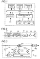
- FIG. 1 is a block diagram illustrating a configuration of a speaker apparatus 1 in an embodiment of the invention.
- the speaker apparatus 1 includes a control unit 2, a storage unit 3, an operation unit 4, an interface 5 and a sound processing unit 10.
- the respective constitutional elements are connected via buses.
- the sound processing unit 10 is connected with a speaker unit 21 and a microphone unit 22.
- the control unit 2 has a CPU (Central Processing Unit), a RAM (Random Access Memory), a ROM (Read Only Memory) and the like.
- the control unit 2 executes a control program stored in the storage unit 3 or ROM, thereby controlling the respective parts of the speaker apparatus 1 via the bus.
- the control unit 2 controls the sound processing unit 10, thereby implementing respective configurations for performing correction processing and measuring processing in the sound processing unit 10.
- the correction processing is performed in the speaker apparatus 1 so as to reduce an influence of indirect sound from sound that is output from the speaker apparatus 1 and then a listener hears at a sound receiving point.
- the measuring processing is performed in the sound processing unit 10 when the control unit 2 performs setting processing of setting parameters that are used in the correction processing.
- the setting processing is performed when changing an environment such as a provision position of the speaker apparatus 1, a room in which the speaker apparatus is provided, a sound receiving position and the like, and starts as a user operates the operation unit 4.
- the storage unit 3 corresponds to storage means such as non-volatile memory and stores a setting parameter and the like that are used in the control of the control unit 2.
- the setting parameter includes parameters that are set in a correction processing unit 102 (an indirect sound adjusting unit 1021, a frequency characteristic adjusting unit 1022), which will be described later.
- the operation unit 4 has an operation means such as a volume for adjusting a volume level and an operation button for inputting an instruction to change a setting, and the operation unit 4 outputs information indicating operation contents to the control unit 2.
- the interface 5 indicates an input terminal for acquiring an audio signal Sin from the outside, and the like.
- the speaker unit 21 corresponds to sound emission means that outputs an input audio signal as sound, and has a digital/analog conversion unit (D/A) 211 that converts an audio signal of the input digital signal into an analog signal, an amplification unit 212 that amplifies and outputs the input audio signal and a speaker unit 213 that outputs the input audio signal as sound (refer to FIGS. 2 and 4 ).
- the sets of the respective configurations of the speaker unit 21 are provided in correspondence to the number of channels capable of making an output. When each configuration of the speaker unit 21 is two sets, each set corresponds to an L channel and an R channel of the audio signal, for example.
- the speaker unit 213 may be a speaker array consisting of a plurality of speaker units, other than a single speaker unit.
- the microphone unit 22 has a substantially non-directional microphone 221 that outputs input sound as an audio signal and an analog/digital conversion unit (A/D) 222 that converts the audio signal of the input analog signal into a digital signal (refer to FIG. 4 ).
- A/D analog/digital conversion unit
- the sound processing unit 10 performs a variety of processing for the audio signal in response to the control of the control unit 2. In the below, the respective configurations of the sound processing unit 10 for performing the correction processing are described.
- FIG. 2 is a block diagram illustrating a configuration of the sound processing unit 10 for performing correction processing in the embodiment of the invention.
- the correction processing in the sound processing unit 10 is implemented by a signal processing unit 101 and a correction processing unit 102.
- the correction processing unit 102 operates, based on parameters that are set under control of the control unit 2.
- the parameters are set by setting processing, and the setting content thereof is stored in the storage unit 3, as described above.
- the sound processing unit 10 may have a memory that stores the setting content.
- the signal processing unit 101 acquires the audio signal Sin input to the interface 5, performs a variety of signal processing such as decode processing, equalizer processing, sound effect processing and the like for the audio signal and outputs the same.
- the correction processing unit 102 performs the correction processing for the audio signal output from the signal processing unit 101 and then outputs the same to the speaker unit 21.
- correction processing unit 102 The detailed configuration of the correction processing unit 102 is described with reference to FIG. 3 .
- FIG. 3 is a block diagram illustrating a configuration of the correction processing unit 102 in the embodiment of the invention.
- the correction processing unit 102 has an indirect sound adjusting unit 1021 that performs indirect sound adjusting processing for the audio signal and a frequency characteristic adjusting unit (EQ) 1022 that performs frequency characteristic adjusting processing for the audio signal.
- EQ frequency characteristic adjusting unit
- an output signal from the indirect sound adjusting unit 1021 is input to the frequency characteristic adjusting unit 1022.
- the indirect sound adjusting processing and the frequency characteristic adjusting processing are linear processing, respectively, a structure may be also possible in which an output signal from the frequency characteristic adjusting unit 1022 is input to the indirect sound adjusting unit 1021. That is, the processing in the indirect sound adjusting unit 1021 and the frequency characteristic adjusting unit 1022 is preferably performed in a cascade manner for the audio signal input to the correction processing unit 102.
- the indirect sound adjusting unit 1021 performs the processing for the input audio signal with a low-pass filter (LPF) and a multi-tap delay having a plurality of delay processing units, adds the processed audio signal to the original audio signal and outputs the same.
- the series of processing is referred to as indirect sound adjusting processing.
- the indirect sound adjusting unit 1021 includes an input level adjusting unit 111, a low-pass filter 112, a delay unit 113 having a plurality of taps, level adjusting units 114-1, 114-2, ..., 114-n and an adding unit 115.
- the multi-tap delay is configured by the delay unit 113 and the level adjusting units 114-1, 114-2, ..., 114-n.
- the input level adjusting unit 111 adjusts an input level by amplifying the audio signal, which is input to the low-pass filter 112 and a signal line of the multi-tap delay, with an amplification factor corresponding to the control of the control unit 2. Meanwhile, such configuration may not be provided.
- the low-pass filter 112 has a cutoff frequency Fc set therein and attenuates a component of a frequency band higher than the cutoff frequency Fc from the audio signal acquired from the input level adjusting unit 111, thereby extracting and outputting the audio signal of the cutoff frequency Fc or lower.
- the cutoff frequency Fc is 500 Hz (about 70 cm in terms of wavelength).
- the cutoff frequency Fc is set as a frequency so that a wavelength thereof becomes a length several times longer than a size of a person's head, and about 1 kHz or lower is preferable.
- a user may designate the setting value by operating the operation unit 4.
- delay times (d1, d2, ..., dn) are set by the control of the control unit 2, in correspondence to the respective signal lines (taps).
- the delay time is set to be time of 50 milliseconds or shorter corresponding to a temporal resolution of an auditory sense.
- the delay unit 113 performs the delay processing of the delay time set in correspondence to the respective signal lines for the input audio signal and then outputs the same from the respective signal lines.
- the level adjusting units 114-1, 114-2, ..., 114-n are provided in correspondence to respective signal output lines from the delay unit 113.
- Amplification factors (g1, g2, ..., gn) are set for the level adjusting units 114-1, 114-2, ..., 114-n in response to the control of the control unit 2.
- the level adjusting units 114-1, 114-2, ..., 114-n amplify and output the audio signals, which are output to the respective signal output lines, with the amplification factors that are respectively set.
- the outputs of the respective signal lines from the level adjusting units 114-1, 114-2, ..., 114-n correspond to the outputs from the respective delay processing units in the multi-tap delay.
- each of the delay processing units included in the multi-tap delay has a delay circuit that performs the delay processing for the signal output from the delay unit 113 to one signal line and one level adjusting unit that performs amplifying processing for the signal output to the signal line.
- the respective parameters (delay time in the delay unit 113, amplification factors in the level adjusting units 114-1, 114-2, ..., 114-n) set in the multi-tap delay are hereinafter referred to as first parameter.
- the adding unit 115 adds the audio signals, which are output from the level adjusting units 114-1, 114-2, ..., 114-n, to the original audio signal (audio signal for which the signal processing has not been performed by the signal line of the delay unit 113) input to the indirect sound adjusting unit 1021 and then outputs the same.
- the frequency characteristic adjusting unit 1022 is a parametric equalizer that uses an IIR (Infinite impulse response) filter, an FIR (Finite impulse response) filter and the like, and adjusts and outputs the frequency characteristic of the input audio signal, based on parameters set by the control of the control unit 2 (for example, the frequency characteristic that is determined by a central frequency, a bandwidth, a gain value and the like, which is hereinafter referred to as a second parameter). This processing is referred to as frequency characteristic adjusting processing.
- IIR Infinite impulse response
- FIR Finite impulse response
- the correction processing unit 102 is configured as described above. In the below, the setting processing is described.
- FIG. 4 is a block diagram illustrating a configuration of performing the setting processing in the embodiment of the invention.
- the setting processing is implemented by a specifying unit 201, a setting unit 202, a measuring signal generation unit 103 and a response calculation unit 104.
- the measuring processing that is performed in the sound processing unit 10 is implemented by the measuring signal generation unit 103 and the response calculation unit 104.
- the specifying unit 201 and the setting unit 202 are configured by the control unit 2.
- the speaker unit 213 of the speaker apparatus 1 that is provided in the room is provided at the same position as a case where a listener actually hears.
- the setting processing is performed in correspondence to each of the sets. In the below, a case where the speaker unit 21 has one set is exemplified.
- the microphone 221 is provided at the sound receiving position that is a listener position.
- the measuring signal generation unit 103 generates a measuring signal in response to the control of the control unit 2 and outputs the same to the speaker unit 21.
- the measuring signal is a signal that indicates impulse sound, for example.
- the speaker unit 21 outputs measuring sound Ms that indicates the measuring signal (measuring sound output processing).
- the microphone 221 is input with sound in which the indirect sound and the like in the room are included in the measuring sound Ms, and the microphone unit 22 outputs a measuring result signal that indicates a content of the sound input to the microphone 221.
- the response calculation unit 104 compares the measuring result signal, which is output from the microphone unit 22, and the measuring signal, which is generated from the measuring signal generation unit 103, calculates an impulse response and measures the same as an impulse response (hereinafter, referred to as measured impulse response) at the sound receiving point (impulse response measuring processing).
- the measuring signal is impulse sound
- the measuring result signal becomes a signal that indicates the measured impulse response.
- the specifying unit 201 analyzes the signal that indicates the measured impulse response, performs the correction processing for a measuring signal indicating the measuring sound Ms in the correction processing 102, then outputs the same to the speaker unit 21 and outputs the same from the speaker unit 213 as sound, the specifying unit 201 calculates a response (hereinafter, referred to as an estimated impulse response) that is estimated as the impulse response at the sound receiving point (impulse response analysis processing).
- a response hereinafter, referred to as an estimated impulse response
- the specifying unit 201 calculates the estimated impulse response with respect to a case where the correction processing is performed by changing the first parameter (delay time, amplification factor), which is set in the multi-tap delay (delay unit 113 and level adjusting units 114-1, 114-2, ..., 114-n), in several ways.
- the input level adjusting unit 111 is fixed with an amplification factor that is determined in advance, and is set by the control unit 2.
- the frequency characteristic adjusting unit 1022 is fixed with a second parameter that is determined in advance, and is set by the control unit 2.
- the second parameter is set to be a value in which the frequency characteristic adjusting processing is not performed, i.e., the frequency characteristic as the equalizer is flat.
- the specifying unit 201 compares the signals indicating a plurality of estimated impulse responses that are calculated in correspondence to cases where a plurality of different values are determined as the first parameter, respectively. Then, as a result of the comparison, the specifying unit 201 specifies a value of the signal having energy that becomes smaller from the plurality of values, as the first parameter (first parameter specifying processing).
- the specifying unit 201 specifies the second parameter, based on the frequency characteristic of the indirect sound adjusting processing when the first parameter is set in the indirect sound adjusting unit 1021 (second parameter specifying processing). At this time, the second parameter is specified so that it becomes a reverse characteristic of the frequency characteristic of the indirect sound adjusting processing.
- the first parameter specifying processing and the second parameter specifying processing in the specifying unit 201 will be specifically described in the corresponding processing.
- the setting unit 202 acquires the first parameter and the second parameter specified in the specifying unit 201, sets the first parameter in the delay unit 113 and the level adjusting units 114-1, 114-2, ..., 114-n of the indirect sound adjusting unit 1021, and sets the second parameter in the frequency characteristic adjusting unit 1022 (parameter setting processing).
- FIG. 5 is a flowchart illustrating a parameter setting method in the embodiment of the invention.
- the measuring signal generation unit 103 outputs a measuring signal in response to the control of the control unit 2 and outputs a measuring sound Ms from the speaker unit 213 (measuring sound output processing, step S110).
- the response calculation unit 104 compares the measuring result signal with the measuring signal and then calculates a measured impulse response at the sound receiving point (impulse response measuring processing, step S120).
- the specifying unit 201 analyzes the measured impulse response (impulse response analysis processing, step S130), calculates a plurality of estimated impulse responses and specifies the first parameter (delay time, amplification factor), based on the signal energy of the estimated impulse responses (first parameter specifying processing, step S 140).
- the impulse response analysis processing (step S 130) and the first parameter specifying processing (step S 140) are described with reference to FIGS. 6A and 6B .
- FIGS. 6A and 6B illustrate an example of the impulse response analysis processing in the embodiment of the invention.
- the specifying unit 201 activates the delay unit 113 and only the first signal line and inactivates the other signal lines among the level adjusting units 114-1, 114-2, ..., 114-n.
- the inactivation may mean that a signal is not output from the delay unit 113 to the corresponding signal line or that the amplification factor set in the level adjusting unit on the corresponding signal line is set to be 'zero (0).'
- the specifying unit 201 performs the correction processing for the measuring signal indicating the measuring sound Ms when the delay time d1 and the amplification factor g1 are temporarily set with various values, and calculates an estimated impulse response that is estimated as an impulse response at the sound receiving point when outputting the correction-processed signal from the speaker unit 213 as sound.
- the delay time d1 that is set as the first parameter is temporarily set to be larger than 0 millisecond and to be 50 milliseconds or shorter and a value thereof to be taken may be a sample unit or one millisecond unit.
- the amplification factor g1 that is the other first parameter is temporarily set to be a value between -xdB and +ydB, and a value thereof to be taken may be a preset unit such as 1 dB unit. Also, the amplification factor g1 may be a value for inversion processing.
- the specifying unit 201 compares the respective signals, which indicate the plurality of estimated impulse responses calculated in correspondence to the first parameter (delay time d1 and amplification factor g1) having a plurality of different values, and selects an estimated impulse response having the lowest energy in a preset evaluation time period Ta.
- the evaluation time period Ta is a time period following the signal corresponding to the direct sound in the impulse response, and a span thereof is set to be 100 milliseconds or shorter.
- the span is preferably set to be about a double or smaller of the maximum value of the delay time set in the delay unit 113, but the value is not limited thereto.
- the specifying unit 201 may specify a frequency of the stationary wave component and thus change the setting so that the cutoff frequency Fc set in the low-pass filter 112 becomes higher than the frequency of the stationary wave component.
- the specifying unit 201 specifies a value corresponding to the selected estimated impulse response as the first parameter (delay time d1, amplification factor g1).
- the specifying unit 201 sets the first parameter (delay time d1, amplification factor g1) specified in correspondence to the first signal line and fixes the value. Then, the specifying unit 201 activates the first and second signal lines, performs the correction processing for the measuring signal indicating the measuring sound Ms when the delay time d2 and the amplification factor g2 are temporarily set with various values, and calculates an estimated impulse response that is estimated as an impulse response at the sound receiving point when outputting the correction-processed signal from the speaker unit 213 as sound. Also, like the first signal line, the specifying unit 201 calculates a plurality of estimated impulse responses, selects one estimated impulse response and specifies a value corresponding to the selected estimated impulse response as the first parameter (delay time d2, amplification factor g2).
- the specifying unit 201 repeats the above processing.
- the specifying unit 201 ends the first parameter specifying processing.
- the specifying unit 201 calculates a frequency characteristic (for example, refer to FIG. 8 ) of the indirect sound adjusting processing where the first parameters specified in correspondence to all the signal lines are set in the indirect sound adjusting unit 1021, and specifies a reverse characteristic of the frequency characteristic as the second parameter (frequency characteristic) (second parameter specifying processing, step S150). At this time, it is not necessarily required that the reverse characteristic of the frequency characteristic of the indirect sound adjusting processing should coincide with the frequency characteristic of the frequency characteristic adjusting processing.
- a frequency characteristic for example, refer to FIG. 8
- the reverse characteristic of the frequency characteristic from which the characteristic peak or dip has been extracted may be set as the frequency characteristic of the frequency characteristic adjusting processing.
- the specifying unit 201 may calculate the frequency characteristic of the indirect sound adjusting processing by calculating a frequency characteristic for a circuit where the specified first parameter is set. Also, the specifying unit 201 may perform the calculation while assuming that a difference between the frequency characteristic of the estimated impulse response when the specified first parameter is set in the indirect sound adjusting unit 1021 and the frequency characteristic of the measured impulse response is attributed to the processing frequency characteristic of the indirect sound adjusting unit 1021. At this time, it may be possible to use an estimated impulse response that is obtained when all the amplification factors of the first parameter are set to be 'zero (0)', instead of the measured impulse response.
- the setting unit 202 sets the parameters specified by the specifying unit 201 in the delay unit 113 and the level adjusting units 114-1, 114-2, ..., 114-n of the indirect sound adjusting unit 1021 and sets the second parameter in the frequency characteristic adjusting unit 1022 (parameter setting processing, step S160).
- the control unit 2 ends the parameter setting processing.
- the parameter setting method is as described above.
- a difference of the impulse responses at the sound receiving point is exemplified when the correction processing is performed by using the correction processing unit 102 in which the parameters are set as described above and when the correction processing is not performed.
- the difference is described, depending on whether the indirect sound adjusting processing is performed or not and whether the frequency characteristic adjusting processing is performed or not.
- FIGS. 7A and 7B illustrate a difference of the impulse responses, depending on the presence of the indirect sound adjusting processing in the embodiment of the invention.
- a horizontal axis indicates time in which '0' indicates time at which the measuring signal is output
- a vertical axis indicates a signal level.
- a horizontal axis indicates a frequency
- a vertical axis indicates a signal level.
- the frequency characteristic adjusting processing has not been performed.
- FIG. 7A compares an impulse response signal IR(0) when the indirect sound adjusting processing has not been performed with an impulse response signal IR(n) when the indirect sound adjusting processing has been performed for a case where the parameters have been set in the multi-tap delay having the n signal lines in the indirect sound adjusting unit 1021 according to the above-described parameter setting method.
- FIG. 7A shows signals of the impulse response signals IR(0) and IR(n), which are obtained by extracting only frequency bands of the cutoff frequency Fc (500 Hz) or lower set in the low-pass filter 112, so as to easily compare the impulse response signals.
- the impulse response signal IR(n) has the energy lower than the impulse response signal IR(0) in the evaluation time period Ta.
- the peaks are generally suppressed in the evaluation time period Ta.
- the listener hears the sound in which the influence of the indirect sound that reaches in the evaluation time period Ta, i.e., a time period shorter than the temporal resolution of the auditory sense has been reduced by the decrease in the energy. Therefore, the listener can hear the sound having the improved sound quality, compared to the case where the indirect sound adjusting processing has not been performed.
- FIG. 7B shows the frequency characteristics of the impulse response signals IR(0) and IR(n) shown in FIG. 7A .
- the spectra indicating the frequency characteristics of the impulse response signals IR(0) and IR(n) are IRF(0) and IRF(n), respectively.
- FIGS. 7A and 7B it can be seen that the energy is suppressed in the low frequency band passing to the low-pass filter 112 by the indirect sound adjusting processing. Particularly, the energy is largely suppressed in the vicinity of 100 Hz. Therefore, when the listener hears such sound, the listener may feel that there is something lacking in the low frequency band.
- FIG. 8 illustrates a frequency characteristic of the indirect sound adjusting processing in the embodiment of the invention.
- a horizontal axis indicates a frequency and a vertical axis indicates a signal level.
- a spectrum indicating the frequency characteristic of the indirect sound adjusting processing is CF(n).
- the frequency characteristic CF(n) is calculated as the frequency characteristic of a circuit where the parameters have been set in the multi-tap delay having the n signal lines in the indirect sound adjusting unit 1021 according to the above-described parameter setting method.
- FIG. 7B the energy around 100 Hz is largely suppressed by the indirect sound adjusting processing of this example.
- the frequency characteristic of the indirect sound adjusting processing shows a characteristic that a dip largely lowering the level around 100 Hz is seen.
- FIGS. 9A and 9B illustrate a difference of impulse responses, depending on the presence of frequency characteristic adjusting processing in the embodiment of the invention.
- a horizontal axis indicates time in which '0' indicates time at which the measuring signal is output, and a vertical axis indicates a signal level.
- a horizontal axis indicates a frequency and a vertical axis indicates a signal level.
- the frequency characteristic adjusting processing is performed when the second parameter is set in the frequency characteristic adjusting unit 1022 as the reverse characteristic of the frequency characteristic shown in FIG. 8 .
- the second parameter is determined so as to reflect the reverse characteristic (around 100 Hz) of the characteristic dip part, other than the reverse characteristic itself.
- the second parameter is set so that the central frequency is '100 Hz', the bandwidth is a specific width (which may be a predetermined specific width) that is determined depending on the half-value width of the dip part and the gain becomes a peak characteristic of '+5dB.
- FIG. 9A compares an impulse response signal IR(n) when the indirect sound adjusting processing has not been performed with an impulse response signal IRE(n) when the indirect sound adjusting processing has been performed.
- FIG. 9A shows signals of the impulse response signals IR(n) and IRE(n), which are obtained by extracting only frequency bands of the cutoff frequency Fc (500 Hz) or lower set in the low-pass filter 112, so as to easily compare the impulse response signals.
- FIG. 9B shows the frequency characteristics of the impulse response signals IR(n) and IRE(n) shown in FIG. 9A .
- the spectra indicating the frequency characteristics of the impulse response signals IR(n) and IRE(n) are IRF(n) and IREF(n), respectively.
- the frequency characteristic adjusting processing the energy around 100 Hz is increased and the deficiency that the listener feels is reduced.
- FIGS. 10A and 10B illustrate a difference of impulse responses, depending on the presence of the correction processing in the embodiment of the invention.
- FIG. 10A compares the impulse response IR(0) shown in FIG. 7A with the impulse response IRE(n) shown in FIG. 9A
- FIG. 10B compares the impulse response IRF(0) shown in FIG. 7B with the impulse response IREF(n) shown in FIG. 9B .
- the peak appearing in the impulse response IR(0) is suppressed in the impulse response IRE(n) by the correction processing.
- FIGS. 10A compares the impulse response IR(0) shown in FIG. 7A with the impulse response IRE(n) shown in FIG. 9A
- FIG. 10B compares the impulse response IRF(0) shown in FIG. 7B with the impulse response IREF(n) shown in FIG. 9B .
- the peak appearing in the impulse response IR(0) is suppressed in the impulse response IRE(n) by the correction processing.
- FIGS. 10A illustrates a difference of impulse responses,
- the second parameter is determined so that the impulse response IREF(n) is more approximate to the impulse response IRF(0) than the impulse response IRF(n), and the impulse responses IREF(n) and IRF(0) have the substantially same spectrum, respectively. Therefore, it is possible to reduce the deficiency that the listener feels while suppressing the influence of the indirect sound to be exerted on the sound quality by the correction processing.
- the speaker apparatus 1 performs the correction processing for the input audio signal Sin and then outputs the same as the sound.
- the listener located at the sound receiving point hears the sound with the influence of the indirect sound being reduced in the evaluation time period Ta.
- the influence of the indirect sound is reduced in the low frequency band passing through the low-pass filter 112.
- the frequency characteristic of the audio signal is less changed before and after the correction processing, the energy is not suppressed in a specific frequency band, so that the listener does not feel the deficiency well.
- the cutoff frequency Fc that is set in the low-pass filter 112 is set as a frequency so that a wavelength thereof becomes a length several times longer than a size of a person's head. Therefore, the influence of the indirect sound is reduced in a range of the wavelength about the sound receiving point.
- the correction processing is performed by using the audio signal that does not pass through the low-pass filter 112, the correction processing is made even for the sound in a high frequency band having a short wavelength.
- the position of the listener (sound receiving point) is moved beyond the range of the wavelength, the correction effect in the high frequency band is reduced and the adverse effect may be exerted on the sound quality.
- the correction processing is performed by using the audio signal having passed through the low-pass filter 112.
- the specifying unit 201 specifies the first parameter so that the energy of the impulse response signal IR(n) in the evaluation time period Ta when the indirect sound adjusting processing is performed is smaller than the energy of the impulse response signal IR(0) in the evaluation time period Ta when the indirect sound adjusting processing is not performed, thereby reducing the influence of the indirect sound.
- the first parameter may be specified in other ways.
- the specifying unit 201 may specify the first parameter so that a peak value of an absolute value of the impulse response signal IR(n) in the evaluation time period Ta is smaller than a peak value of an absolute value of the impulse response signal IR(0) in the evaluation time period Ta, thereby reducing reduce the influence of the indirect sound.
- the specifying unit 201 compares the respective signals, which indicate the plurality of estimated impulse responses calculated in correspondence to the first parameter (delay time, amplification factor) having a plurality of different values, and selects an estimated impulse response having the smallest maximum value of the peak values of the absolute values in the evaluation time period Ta.
- the specifying unit 201 may specify the first parameter so that a variation in the frequency characteristic of the impulse response signal IR(n) is smaller than a variation in the frequency characteristic of the impulse response signal IR(0), thereby reducing reduce the influence of the indirect sound.
- the specifying unit 201 compares the respective signals, which indicate the plurality of estimated impulse responses calculated in correspondence to the first parameter (delay time, amplification factor) having a plurality of different values, and selects an estimated impulse response having the smallest variation in the frequency characteristic.
- the estimated impulse response is selected so that the energy, the peak value and the variation in the frequency characteristic become smaller.
- the estimated impulse response may be selected so that the energy, the peak value and the variation in the frequency characteristic become larger or approximate to a constant value.
- the estimated impulse response may be used for reproducing a special sound field and the like.
- the second parameter since the energy in a specific frequency band may be increased by the indirect sound adjusting processing, the second parameter may be determined so that the energy in the specific frequency band is decreased in the frequency characteristic adjusting processing.
- the specifying unit 201 calculates the plurality of estimated impulse responses for each signal line and compares the same with the measured impulse response to specify the first parameter, thereby sequentially specifying the first parameter for all the signal lines.
- the specifying unit 201 may specify the first parameter every a plurality of signal lines.
- the specifying unit 201 specifies the first parameter every three signal lines.
- the three signal lines are m, m+1 and m+2.
- the specifying unit 201 calculates a plurality of estimated impulse responses when the corresponding values are variously changed and thus temporarily set.
- the specifying unit 201 compares the signals indicating the plurality of estimated impulse responses and selects an estimated impulse response having the smallest energy in the evaluation time period Ta. Then, the specifying unit 201 specifies a value corresponding to the selected estimated impulse response, as the first parameter (delay time: dm, dm+1, dm+2; and amplification factor: g, gm+1, gm+2).
- the specifying unit 201 specifies the parameter for the m+3th, m+4th and m+5th signal lines by the same method as the above. By continuing the processing, the specifying unit 201 specifies the first parameter that should be set in correspondence to the nth signal line.
- the specifying unit 201 specifies the first parameter for a unit of a plurality of signal lines and thus makes the energy of the impulse response signal IR(n) smaller in the evaluation time period Ta, compared to the case where the specifying unit 201 specifies the first parameter for each single signal line. Also, the larger the number of the signal lines, which becomes a unit when specifying the first parameter, the energy can be further reduced. However, a processing time for calculating the estimated impulse responses is increased. Therefore, the specifying unit 201 preferably integrates all the n signal lines and specifies the first parameter when there is an allowance for processing time. For example, even while the speaker apparatus 1 outputs the sound for which the correction processing has been performed, the specifying unit 201 may perform the processing in the background.
- the specifying unit 201 when the specifying unit 201 specifies the first parameter in correspondence to the one signal line, the specifying unit 201 specifies the first parameter corresponding to a next signal line and ends the processing when the first parameter is also specified for the nth signal line. Alternatively, the specifying unit 201 may end the processing even though it does not reach the nth signal line when a predetermined condition is satisfied.
- the specifying unit 201 ends the processing without specifying the first parameter for a p+2th ( ⁇ n) signal line. Then, the specifying unit 201 inactivates the signal lines after p+2th (or p+1th) so that they are not used in the correction processing.
- the low-pass filter 112 is provided on the signal path prior to the delay unit 113.
- the low-pass filter 112 may be provided on the signal line after the delay unit 113 owing to the cascade connection of the linear invariant system. That is, the low-pass filter 112 may be provided on the signal line before the audio signal, which has been processed in the delay unit 113 and the level adjusting units 114-1, 114-2, ..., 114-n, is added to the original audio signal, which is input to the indirect sound adjusting unit 1021, in the adding unit 115.
- a second adding unit that first adds the audio signal output from the level adjusting units 114-1, 114-2, ..., 114-n may be provided and the audio signal output from the second adding unit may be processed in the low-pass filter 112 and then output to the adding unit 115.
- the low-pass filter 112 is not necessarily required. That is, in an environment in which the position of the listener is little changed, the effect of reducing the influence of the indirect sound is not lost well even when the low-pass filter 112 is not provided.
- the input level adjusting unit 111 is fixed with the preset amplification factor.
- the amplification factor may be changed after the first parameter specifying processing.
- the frequency characteristic of the indirect sound adjusting processing is varied, when the amplification factor is varied after the second parameter specifying processing, the content of the second parameter may be updated as the amplification factor is varied.
- the influence of the indirect sound that is exerted on the sound quality is adjusted by using the input level adjusting unit 111, the low-pass filter 112, the delay unit 113 and the level adjusting units 114-1, 114-2, ..., 114-n.
- the other configuration may be also used.
- the signal processing in a part or all of the configurations may be implemented with a digital filter such as FIR filter.
- the first parameter that is determined to adjust the influence of the indirect sound exerted on the sound quality corresponds to a coefficient of the FIR filter.
- the indirect sound adjusting unit 1021 adds the audio signal for which the signal processing has been performed by the FIR filter to the audio signal for which the signal processing has not been performed and outputs the same.
- the indirect sound adjusting unit 1021 may have any configuration insomuch as it has a configuration of performing the signal processing, which is determined to adjust the influence of the indirect sound exerted on the sound quality, for an audio signal, adding the audio signal to an audio signal for which the signal processing has not been performed and outputting the same.
- the sound processing apparatus (an apparatus having at least the control unit 2 and the sound processing unit 10) in the embodiment is applied to the speaker apparatus 1.
- the invention is not limited to the speaker apparatus 1.
- the sound processing apparatus can be also applied to an AV (Audio Visual) amplifier, an AV receiver and the like to which the speaker unit 213 and the microphone 221 are connected as the external apparatuses.
- the sound processing apparatus can be applied to a television, a personal computer (PC), a gaming machine and the like.
- a control program of the above embodiment can be provided as stored in a computer-readable recording medium such as magnetic recording medium (magnetic tape, magnetic disk and the like), optical recording medium (optical disk and the like), magneto optical disk, semiconductor memory and the like. Also, the speaker apparatus 1 may download the control program via the network.
- a computer-readable recording medium such as magnetic recording medium (magnetic tape, magnetic disk and the like), optical recording medium (optical disk and the like), magneto optical disk, semiconductor memory and the like.
- the speaker apparatus 1 may download the control program via the network.
- the signal processing unit 101 acquires the audio signal Sin input to the interface 5. If the sound processing apparatus 1 has a capability of generating an audio signal, however, the signal processing unit 101 may acquires the audio signal which is generated in the sound processing apparatus 1 instead of acquiring the audio signal Sin input to the interface 5.
Landscapes
- Physics & Mathematics (AREA)
- Engineering & Computer Science (AREA)
- Acoustics & Sound (AREA)
- Signal Processing (AREA)
- Circuit For Audible Band Transducer (AREA)
- Stereophonic System (AREA)
- Reverberation, Karaoke And Other Acoustics (AREA)
Applications Claiming Priority (1)
| Application Number | Priority Date | Filing Date | Title |
|---|---|---|---|
| JP2011114165A JP5348179B2 (ja) | 2011-05-20 | 2011-05-20 | 音響処理装置およびパラメータ設定方法 |
Publications (3)
| Publication Number | Publication Date |
|---|---|
| EP2530952A2 true EP2530952A2 (de) | 2012-12-05 |
| EP2530952A3 EP2530952A3 (de) | 2014-12-03 |
| EP2530952B1 EP2530952B1 (de) | 2017-07-12 |
Family
ID=46201360
Family Applications (1)
| Application Number | Title | Priority Date | Filing Date |
|---|---|---|---|
| EP12003931.8A Active EP2530952B1 (de) | 2011-05-20 | 2012-05-18 | Tonverarbeitungsvorrichtung und Parametereinstellverfahren |
Country Status (3)
| Country | Link |
|---|---|
| US (1) | US9743214B2 (de) |
| EP (1) | EP2530952B1 (de) |
| JP (1) | JP5348179B2 (de) |
Citations (2)
| Publication number | Priority date | Publication date | Assignee | Title |
|---|---|---|---|---|
| JPS60223295A (ja) | 1984-04-18 | 1985-11-07 | Pioneer Electronic Corp | 音場補正装置 |
| JPH0549098A (ja) | 1991-08-14 | 1993-02-26 | Matsushita Electric Works Ltd | 音場再生装置 |
Family Cites Families (17)
| Publication number | Priority date | Publication date | Assignee | Title |
|---|---|---|---|---|
| US3158695A (en) * | 1960-07-05 | 1964-11-24 | Ht Res Inst | Stereophonic system |
| JPS55151808A (en) * | 1979-05-15 | 1980-11-26 | Matsushita Electric Ind Co Ltd | Correcting device for acoustic transmission characteristic |
| JPH07105983B2 (ja) * | 1984-04-18 | 1995-11-13 | パイオニア株式会社 | 音場補正装置 |
| DE3579732D1 (de) * | 1984-04-09 | 1990-10-25 | Pioneer Electronic Corp | Schallfeldverbesserungssystem. |
| JPS6327895A (ja) * | 1986-07-22 | 1988-02-05 | 富士通株式会社 | 残響付加方式 |
| JPH03129911A (ja) * | 1989-10-16 | 1991-06-03 | Matsushita Electric Ind Co Ltd | 音響特性制御装置 |
| JPH06223294A (ja) | 1993-01-26 | 1994-08-12 | Shizuki Denki Seisakusho:Kk | 信号灯の補助装置 |
| JP3263178B2 (ja) * | 1993-05-19 | 2002-03-04 | 株式会社日立製作所 | 衣類乾燥機 |
| US5774562A (en) * | 1996-03-25 | 1998-06-30 | Nippon Telegraph And Telephone Corp. | Method and apparatus for dereverberation |
| US7333863B1 (en) * | 1997-05-05 | 2008-02-19 | Warner Music Group, Inc. | Recording and playback control system |
| JP4810541B2 (ja) * | 2004-10-26 | 2011-11-09 | バーウエン,リチヤード・エス | 自然でない反響 |
| KR100739691B1 (ko) | 2005-02-05 | 2007-07-13 | 삼성전자주식회사 | 음장 효과 재생을 위한 사운드 초기 반사음 재생 장치 및방법 |
| US8036767B2 (en) | 2006-09-20 | 2011-10-11 | Harman International Industries, Incorporated | System for extracting and changing the reverberant content of an audio input signal |
| EP2045620B1 (de) | 2007-09-26 | 2015-08-12 | Harman Becker Automotive Systems GmbH | Messung der akustischen Laufzeit |
| JP2010021982A (ja) * | 2008-06-09 | 2010-01-28 | Mitsubishi Electric Corp | 音響再生装置 |
| JPWO2010076850A1 (ja) * | 2009-01-05 | 2012-06-21 | パナソニック株式会社 | 音場制御装置及び音場制御方法 |
| EP2494792B1 (de) * | 2009-10-27 | 2014-08-06 | Phonak AG | Verfahren und System zur Sprachverbesserung |
-
2011
- 2011-05-20 JP JP2011114165A patent/JP5348179B2/ja active Active
-
2012
- 2012-05-18 US US13/474,878 patent/US9743214B2/en active Active
- 2012-05-18 EP EP12003931.8A patent/EP2530952B1/de active Active
Patent Citations (2)
| Publication number | Priority date | Publication date | Assignee | Title |
|---|---|---|---|---|
| JPS60223295A (ja) | 1984-04-18 | 1985-11-07 | Pioneer Electronic Corp | 音場補正装置 |
| JPH0549098A (ja) | 1991-08-14 | 1993-02-26 | Matsushita Electric Works Ltd | 音場再生装置 |
Also Published As
| Publication number | Publication date |
|---|---|
| JP2012242686A (ja) | 2012-12-10 |
| JP5348179B2 (ja) | 2013-11-20 |
| EP2530952B1 (de) | 2017-07-12 |
| US9743214B2 (en) | 2017-08-22 |
| US20120294460A1 (en) | 2012-11-22 |
| EP2530952A3 (de) | 2014-12-03 |
Similar Documents
| Publication | Publication Date | Title |
|---|---|---|
| JP6633239B2 (ja) | ダウンミックスされたオーディオ・コンテンツについてのラウドネス調整 | |
| TWI535299B (zh) | 低音強化系統及其方法 | |
| US9859858B2 (en) | Correction of unknown audio content | |
| CN104798301B (zh) | 音频响度控制系统 | |
| EP2229007B1 (de) | Vorrichtung zur Verarbeitung eines Audiosignals und Verfahren dafür | |
| CN108365827B (zh) | 具有动态阈值的频带压缩 | |
| US9431982B1 (en) | Loudness learning and balancing system | |
| US20190320279A1 (en) | Audio Device | |
| EP2352225A1 (de) | Vorrichtung zur tonsignaleinstellung und verfahren zur tonsignaleinstellung | |
| IL182097A (en) | Evaluation and adjustment of the perceived noise intensity and / or the perceived spectral balance of an audio signal | |
| KR20230156156A (ko) | 라우드니스 레벨을 제어하는 오디오 신호 처리 방법 및 장치 | |
| US9571055B2 (en) | Level adjustment device and method | |
| CN114902560B (zh) | 具有环境噪音补偿的用于自动音量控制的设备和方法 | |
| US11277689B2 (en) | Apparatus and method for optimizing sound quality of a generated audible signal | |
| US9628907B2 (en) | Audio device and method having bypass function for effect change | |
| KR102773326B1 (ko) | 오디오 신호의 정규화를 수행하는 방법 및 이를 위한 장치 | |
| US8660272B2 (en) | Parameter setting method and audio apparatus | |
| CN103812462B (zh) | 响度控制方法及装置 | |
| WO2021133779A1 (en) | Audio device with speech-based audio signal processing | |
| CN107197403B (zh) | 一种终端音频参数管理方法、装置及系统 | |
| EP3379847B1 (de) | Audiogerät, lautsprecher und audiosignalverarbeitungsverfahren | |
| US20230360662A1 (en) | Method and device for processing a binaural recording | |
| US9743214B2 (en) | Sound processing apparatus and parameter setting method | |
| US9666196B2 (en) | Recording apparatus with mastering function | |
| EP3761673A1 (de) | Stereo-audio |
Legal Events
| Date | Code | Title | Description |
|---|---|---|---|
| PUAI | Public reference made under article 153(3) epc to a published international application that has entered the european phase |
Free format text: ORIGINAL CODE: 0009012 |
|
| AK | Designated contracting states |
Kind code of ref document: A2 Designated state(s): AL AT BE BG CH CY CZ DE DK EE ES FI FR GB GR HR HU IE IS IT LI LT LU LV MC MK MT NL NO PL PT RO RS SE SI SK SM TR |
|
| AX | Request for extension of the european patent |
Extension state: BA ME |
|
| PUAL | Search report despatched |
Free format text: ORIGINAL CODE: 0009013 |
|
| AK | Designated contracting states |
Kind code of ref document: A3 Designated state(s): AL AT BE BG CH CY CZ DE DK EE ES FI FR GB GR HR HU IE IS IT LI LT LU LV MC MK MT NL NO PL PT RO RS SE SI SK SM TR |
|
| AX | Request for extension of the european patent |
Extension state: BA ME |
|
| RIC1 | Information provided on ipc code assigned before grant |
Ipc: H04S 7/00 20060101ALN20141024BHEP Ipc: H04R 3/04 20060101AFI20141024BHEP |
|
| 17P | Request for examination filed |
Effective date: 20150603 |
|
| RBV | Designated contracting states (corrected) |
Designated state(s): AL AT BE BG CH CY CZ DE DK EE ES FI FR GB GR HR HU IE IS IT LI LT LU LV MC MK MT NL NO PL PT RO RS SE SI SK SM TR |
|
| 17Q | First examination report despatched |
Effective date: 20151009 |
|
| GRAP | Despatch of communication of intention to grant a patent |
Free format text: ORIGINAL CODE: EPIDOSNIGR1 |
|
| RIC1 | Information provided on ipc code assigned before grant |
Ipc: H04R 3/04 20060101AFI20170110BHEP Ipc: H04S 7/00 20060101ALN20170110BHEP |
|
| RIC1 | Information provided on ipc code assigned before grant |
Ipc: H04S 7/00 20060101ALN20170119BHEP Ipc: H04R 3/04 20060101AFI20170119BHEP |
|
| INTG | Intention to grant announced |
Effective date: 20170206 |
|
| GRAS | Grant fee paid |
Free format text: ORIGINAL CODE: EPIDOSNIGR3 |
|
| GRAA | (expected) grant |
Free format text: ORIGINAL CODE: 0009210 |
|
| AK | Designated contracting states |
Kind code of ref document: B1 Designated state(s): AL AT BE BG CH CY CZ DE DK EE ES FI FR GB GR HR HU IE IS IT LI LT LU LV MC MK MT NL NO PL PT RO RS SE SI SK SM TR |
|
| REG | Reference to a national code |
Ref country code: GB Ref legal event code: FG4D |
|
| REG | Reference to a national code |
Ref country code: CH Ref legal event code: EP |
|
| REG | Reference to a national code |
Ref country code: AT Ref legal event code: REF Ref document number: 909354 Country of ref document: AT Kind code of ref document: T Effective date: 20170715 |
|
| REG | Reference to a national code |
Ref country code: IE Ref legal event code: FG4D |
|
| REG | Reference to a national code |
Ref country code: DE Ref legal event code: R096 Ref document number: 602012034327 Country of ref document: DE |
|
| REG | Reference to a national code |
Ref country code: NL Ref legal event code: MP Effective date: 20170712 |
|
| REG | Reference to a national code |
Ref country code: LT Ref legal event code: MG4D |
|
| REG | Reference to a national code |
Ref country code: AT Ref legal event code: MK05 Ref document number: 909354 Country of ref document: AT Kind code of ref document: T Effective date: 20170712 |
|
| PG25 | Lapsed in a contracting state [announced via postgrant information from national office to epo] |
Ref country code: HR Free format text: LAPSE BECAUSE OF FAILURE TO SUBMIT A TRANSLATION OF THE DESCRIPTION OR TO PAY THE FEE WITHIN THE PRESCRIBED TIME-LIMIT Effective date: 20170712 Ref country code: SE Free format text: LAPSE BECAUSE OF FAILURE TO SUBMIT A TRANSLATION OF THE DESCRIPTION OR TO PAY THE FEE WITHIN THE PRESCRIBED TIME-LIMIT Effective date: 20170712 Ref country code: AT Free format text: LAPSE BECAUSE OF FAILURE TO SUBMIT A TRANSLATION OF THE DESCRIPTION OR TO PAY THE FEE WITHIN THE PRESCRIBED TIME-LIMIT Effective date: 20170712 Ref country code: NL Free format text: LAPSE BECAUSE OF FAILURE TO SUBMIT A TRANSLATION OF THE DESCRIPTION OR TO PAY THE FEE WITHIN THE PRESCRIBED TIME-LIMIT Effective date: 20170712 Ref country code: NO Free format text: LAPSE BECAUSE OF FAILURE TO SUBMIT A TRANSLATION OF THE DESCRIPTION OR TO PAY THE FEE WITHIN THE PRESCRIBED TIME-LIMIT Effective date: 20171012 Ref country code: FI Free format text: LAPSE BECAUSE OF FAILURE TO SUBMIT A TRANSLATION OF THE DESCRIPTION OR TO PAY THE FEE WITHIN THE PRESCRIBED TIME-LIMIT Effective date: 20170712 Ref country code: LT Free format text: LAPSE BECAUSE OF FAILURE TO SUBMIT A TRANSLATION OF THE DESCRIPTION OR TO PAY THE FEE WITHIN THE PRESCRIBED TIME-LIMIT Effective date: 20170712 |
|
| PG25 | Lapsed in a contracting state [announced via postgrant information from national office to epo] |
Ref country code: ES Free format text: LAPSE BECAUSE OF FAILURE TO SUBMIT A TRANSLATION OF THE DESCRIPTION OR TO PAY THE FEE WITHIN THE PRESCRIBED TIME-LIMIT Effective date: 20170712 Ref country code: RS Free format text: LAPSE BECAUSE OF FAILURE TO SUBMIT A TRANSLATION OF THE DESCRIPTION OR TO PAY THE FEE WITHIN THE PRESCRIBED TIME-LIMIT Effective date: 20170712 Ref country code: BG Free format text: LAPSE BECAUSE OF FAILURE TO SUBMIT A TRANSLATION OF THE DESCRIPTION OR TO PAY THE FEE WITHIN THE PRESCRIBED TIME-LIMIT Effective date: 20171012 Ref country code: PL Free format text: LAPSE BECAUSE OF FAILURE TO SUBMIT A TRANSLATION OF THE DESCRIPTION OR TO PAY THE FEE WITHIN THE PRESCRIBED TIME-LIMIT Effective date: 20170712 Ref country code: GR Free format text: LAPSE BECAUSE OF FAILURE TO SUBMIT A TRANSLATION OF THE DESCRIPTION OR TO PAY THE FEE WITHIN THE PRESCRIBED TIME-LIMIT Effective date: 20171013 Ref country code: IS Free format text: LAPSE BECAUSE OF FAILURE TO SUBMIT A TRANSLATION OF THE DESCRIPTION OR TO PAY THE FEE WITHIN THE PRESCRIBED TIME-LIMIT Effective date: 20171112 Ref country code: LV Free format text: LAPSE BECAUSE OF FAILURE TO SUBMIT A TRANSLATION OF THE DESCRIPTION OR TO PAY THE FEE WITHIN THE PRESCRIBED TIME-LIMIT Effective date: 20170712 |
|
| REG | Reference to a national code |
Ref country code: DE Ref legal event code: R097 Ref document number: 602012034327 Country of ref document: DE |
|
| PG25 | Lapsed in a contracting state [announced via postgrant information from national office to epo] |
Ref country code: DK Free format text: LAPSE BECAUSE OF FAILURE TO SUBMIT A TRANSLATION OF THE DESCRIPTION OR TO PAY THE FEE WITHIN THE PRESCRIBED TIME-LIMIT Effective date: 20170712 Ref country code: CZ Free format text: LAPSE BECAUSE OF FAILURE TO SUBMIT A TRANSLATION OF THE DESCRIPTION OR TO PAY THE FEE WITHIN THE PRESCRIBED TIME-LIMIT Effective date: 20170712 Ref country code: RO Free format text: LAPSE BECAUSE OF FAILURE TO SUBMIT A TRANSLATION OF THE DESCRIPTION OR TO PAY THE FEE WITHIN THE PRESCRIBED TIME-LIMIT Effective date: 20170712 |
|
| PLBE | No opposition filed within time limit |
Free format text: ORIGINAL CODE: 0009261 |
|
| STAA | Information on the status of an ep patent application or granted ep patent |
Free format text: STATUS: NO OPPOSITION FILED WITHIN TIME LIMIT |
|
| PG25 | Lapsed in a contracting state [announced via postgrant information from national office to epo] |
Ref country code: IT Free format text: LAPSE BECAUSE OF FAILURE TO SUBMIT A TRANSLATION OF THE DESCRIPTION OR TO PAY THE FEE WITHIN THE PRESCRIBED TIME-LIMIT Effective date: 20170712 Ref country code: SK Free format text: LAPSE BECAUSE OF FAILURE TO SUBMIT A TRANSLATION OF THE DESCRIPTION OR TO PAY THE FEE WITHIN THE PRESCRIBED TIME-LIMIT Effective date: 20170712 Ref country code: SM Free format text: LAPSE BECAUSE OF FAILURE TO SUBMIT A TRANSLATION OF THE DESCRIPTION OR TO PAY THE FEE WITHIN THE PRESCRIBED TIME-LIMIT Effective date: 20170712 Ref country code: EE Free format text: LAPSE BECAUSE OF FAILURE TO SUBMIT A TRANSLATION OF THE DESCRIPTION OR TO PAY THE FEE WITHIN THE PRESCRIBED TIME-LIMIT Effective date: 20170712 |
|
| 26N | No opposition filed |
Effective date: 20180413 |
|
| PG25 | Lapsed in a contracting state [announced via postgrant information from national office to epo] |
Ref country code: SI Free format text: LAPSE BECAUSE OF FAILURE TO SUBMIT A TRANSLATION OF THE DESCRIPTION OR TO PAY THE FEE WITHIN THE PRESCRIBED TIME-LIMIT Effective date: 20170712 |
|
| REG | Reference to a national code |
Ref country code: CH Ref legal event code: PL |
|
| GBPC | Gb: european patent ceased through non-payment of renewal fee |
Effective date: 20180518 |
|
| REG | Reference to a national code |
Ref country code: BE Ref legal event code: MM Effective date: 20180531 |
|
| PG25 | Lapsed in a contracting state [announced via postgrant information from national office to epo] |
Ref country code: MC Free format text: LAPSE BECAUSE OF FAILURE TO SUBMIT A TRANSLATION OF THE DESCRIPTION OR TO PAY THE FEE WITHIN THE PRESCRIBED TIME-LIMIT Effective date: 20170712 |
|
| REG | Reference to a national code |
Ref country code: IE Ref legal event code: MM4A |
|
| PG25 | Lapsed in a contracting state [announced via postgrant information from national office to epo] |
Ref country code: CH Free format text: LAPSE BECAUSE OF NON-PAYMENT OF DUE FEES Effective date: 20180531 Ref country code: LI Free format text: LAPSE BECAUSE OF NON-PAYMENT OF DUE FEES Effective date: 20180531 |
|
| PG25 | Lapsed in a contracting state [announced via postgrant information from national office to epo] |
Ref country code: LU Free format text: LAPSE BECAUSE OF NON-PAYMENT OF DUE FEES Effective date: 20180518 |
|
| PG25 | Lapsed in a contracting state [announced via postgrant information from national office to epo] |
Ref country code: GB Free format text: LAPSE BECAUSE OF NON-PAYMENT OF DUE FEES Effective date: 20180518 Ref country code: FR Free format text: LAPSE BECAUSE OF NON-PAYMENT OF DUE FEES Effective date: 20180531 Ref country code: IE Free format text: LAPSE BECAUSE OF NON-PAYMENT OF DUE FEES Effective date: 20180518 |
|
| PG25 | Lapsed in a contracting state [announced via postgrant information from national office to epo] |
Ref country code: BE Free format text: LAPSE BECAUSE OF NON-PAYMENT OF DUE FEES Effective date: 20180531 |
|
| PG25 | Lapsed in a contracting state [announced via postgrant information from national office to epo] |
Ref country code: MT Free format text: LAPSE BECAUSE OF NON-PAYMENT OF DUE FEES Effective date: 20180518 |
|
| PG25 | Lapsed in a contracting state [announced via postgrant information from national office to epo] |
Ref country code: TR Free format text: LAPSE BECAUSE OF FAILURE TO SUBMIT A TRANSLATION OF THE DESCRIPTION OR TO PAY THE FEE WITHIN THE PRESCRIBED TIME-LIMIT Effective date: 20170712 |
|
| PG25 | Lapsed in a contracting state [announced via postgrant information from national office to epo] |
Ref country code: PT Free format text: LAPSE BECAUSE OF FAILURE TO SUBMIT A TRANSLATION OF THE DESCRIPTION OR TO PAY THE FEE WITHIN THE PRESCRIBED TIME-LIMIT Effective date: 20170712 Ref country code: HU Free format text: LAPSE BECAUSE OF FAILURE TO SUBMIT A TRANSLATION OF THE DESCRIPTION OR TO PAY THE FEE WITHIN THE PRESCRIBED TIME-LIMIT; INVALID AB INITIO Effective date: 20120518 |
|
| PG25 | Lapsed in a contracting state [announced via postgrant information from national office to epo] |
Ref country code: CY Free format text: LAPSE BECAUSE OF FAILURE TO SUBMIT A TRANSLATION OF THE DESCRIPTION OR TO PAY THE FEE WITHIN THE PRESCRIBED TIME-LIMIT Effective date: 20170712 Ref country code: MK Free format text: LAPSE BECAUSE OF NON-PAYMENT OF DUE FEES Effective date: 20170712 |
|
| PG25 | Lapsed in a contracting state [announced via postgrant information from national office to epo] |
Ref country code: AL Free format text: LAPSE BECAUSE OF FAILURE TO SUBMIT A TRANSLATION OF THE DESCRIPTION OR TO PAY THE FEE WITHIN THE PRESCRIBED TIME-LIMIT Effective date: 20170712 |
|
| PGFP | Annual fee paid to national office [announced via postgrant information from national office to epo] |
Ref country code: DE Payment date: 20250521 Year of fee payment: 14 |