EP2530550A1 - Anomaly assessment device and anomaly assessment method of control system - Google Patents
Anomaly assessment device and anomaly assessment method of control system Download PDFInfo
- Publication number
- EP2530550A1 EP2530550A1 EP10844571A EP10844571A EP2530550A1 EP 2530550 A1 EP2530550 A1 EP 2530550A1 EP 10844571 A EP10844571 A EP 10844571A EP 10844571 A EP10844571 A EP 10844571A EP 2530550 A1 EP2530550 A1 EP 2530550A1
- Authority
- EP
- European Patent Office
- Prior art keywords
- error
- control system
- determination
- cpu
- motor generator
- Prior art date
- Legal status (The legal status is an assumption and is not a legal conclusion. Google has not performed a legal analysis and makes no representation as to the accuracy of the status listed.)
- Withdrawn
Links
Images



Classifications
-
- F—MECHANICAL ENGINEERING; LIGHTING; HEATING; WEAPONS; BLASTING
- F02—COMBUSTION ENGINES; HOT-GAS OR COMBUSTION-PRODUCT ENGINE PLANTS
- F02D—CONTROLLING COMBUSTION ENGINES
- F02D41/00—Electrical control of supply of combustible mixture or its constituents
- F02D41/24—Electrical control of supply of combustible mixture or its constituents characterised by the use of digital means
- F02D41/26—Electrical control of supply of combustible mixture or its constituents characterised by the use of digital means using computer, e.g. microprocessor
- F02D41/266—Electrical control of supply of combustible mixture or its constituents characterised by the use of digital means using computer, e.g. microprocessor the computer being backed-up or assisted by another circuit, e.g. analogue
-
- B—PERFORMING OPERATIONS; TRANSPORTING
- B60—VEHICLES IN GENERAL
- B60K—ARRANGEMENT OR MOUNTING OF PROPULSION UNITS OR OF TRANSMISSIONS IN VEHICLES; ARRANGEMENT OR MOUNTING OF PLURAL DIVERSE PRIME-MOVERS IN VEHICLES; AUXILIARY DRIVES FOR VEHICLES; INSTRUMENTATION OR DASHBOARDS FOR VEHICLES; ARRANGEMENTS IN CONNECTION WITH COOLING, AIR INTAKE, GAS EXHAUST OR FUEL SUPPLY OF PROPULSION UNITS IN VEHICLES
- B60K6/00—Arrangement or mounting of plural diverse prime-movers for mutual or common propulsion, e.g. hybrid propulsion systems comprising electric motors and internal combustion engines
- B60K6/20—Arrangement or mounting of plural diverse prime-movers for mutual or common propulsion, e.g. hybrid propulsion systems comprising electric motors and internal combustion engines the prime-movers consisting of electric motors and internal combustion engines, e.g. HEVs
- B60K6/42—Arrangement or mounting of plural diverse prime-movers for mutual or common propulsion, e.g. hybrid propulsion systems comprising electric motors and internal combustion engines the prime-movers consisting of electric motors and internal combustion engines, e.g. HEVs characterised by the architecture of the hybrid electric vehicle
- B60K6/44—Series-parallel type
- B60K6/445—Differential gearing distribution type
-
- B—PERFORMING OPERATIONS; TRANSPORTING
- B60—VEHICLES IN GENERAL
- B60L—PROPULSION OF ELECTRICALLY-PROPELLED VEHICLES; SUPPLYING ELECTRIC POWER FOR AUXILIARY EQUIPMENT OF ELECTRICALLY-PROPELLED VEHICLES; ELECTRODYNAMIC BRAKE SYSTEMS FOR VEHICLES IN GENERAL; MAGNETIC SUSPENSION OR LEVITATION FOR VEHICLES; MONITORING OPERATING VARIABLES OF ELECTRICALLY-PROPELLED VEHICLES; ELECTRIC SAFETY DEVICES FOR ELECTRICALLY-PROPELLED VEHICLES
- B60L15/00—Methods, circuits, or devices for controlling the traction-motor speed of electrically-propelled vehicles
- B60L15/007—Physical arrangements or structures of drive train converters specially adapted for the propulsion motors of electric vehicles
-
- B—PERFORMING OPERATIONS; TRANSPORTING
- B60—VEHICLES IN GENERAL
- B60L—PROPULSION OF ELECTRICALLY-PROPELLED VEHICLES; SUPPLYING ELECTRIC POWER FOR AUXILIARY EQUIPMENT OF ELECTRICALLY-PROPELLED VEHICLES; ELECTRODYNAMIC BRAKE SYSTEMS FOR VEHICLES IN GENERAL; MAGNETIC SUSPENSION OR LEVITATION FOR VEHICLES; MONITORING OPERATING VARIABLES OF ELECTRICALLY-PROPELLED VEHICLES; ELECTRIC SAFETY DEVICES FOR ELECTRICALLY-PROPELLED VEHICLES
- B60L3/00—Electric devices on electrically-propelled vehicles for safety purposes; Monitoring operating variables, e.g. speed, deceleration or energy consumption
- B60L3/0023—Detecting, eliminating, remedying or compensating for drive train abnormalities, e.g. failures within the drive train
-
- B—PERFORMING OPERATIONS; TRANSPORTING
- B60—VEHICLES IN GENERAL
- B60L—PROPULSION OF ELECTRICALLY-PROPELLED VEHICLES; SUPPLYING ELECTRIC POWER FOR AUXILIARY EQUIPMENT OF ELECTRICALLY-PROPELLED VEHICLES; ELECTRODYNAMIC BRAKE SYSTEMS FOR VEHICLES IN GENERAL; MAGNETIC SUSPENSION OR LEVITATION FOR VEHICLES; MONITORING OPERATING VARIABLES OF ELECTRICALLY-PROPELLED VEHICLES; ELECTRIC SAFETY DEVICES FOR ELECTRICALLY-PROPELLED VEHICLES
- B60L3/00—Electric devices on electrically-propelled vehicles for safety purposes; Monitoring operating variables, e.g. speed, deceleration or energy consumption
- B60L3/0023—Detecting, eliminating, remedying or compensating for drive train abnormalities, e.g. failures within the drive train
- B60L3/0084—Detecting, eliminating, remedying or compensating for drive train abnormalities, e.g. failures within the drive train relating to control modules
-
- B—PERFORMING OPERATIONS; TRANSPORTING
- B60—VEHICLES IN GENERAL
- B60L—PROPULSION OF ELECTRICALLY-PROPELLED VEHICLES; SUPPLYING ELECTRIC POWER FOR AUXILIARY EQUIPMENT OF ELECTRICALLY-PROPELLED VEHICLES; ELECTRODYNAMIC BRAKE SYSTEMS FOR VEHICLES IN GENERAL; MAGNETIC SUSPENSION OR LEVITATION FOR VEHICLES; MONITORING OPERATING VARIABLES OF ELECTRICALLY-PROPELLED VEHICLES; ELECTRIC SAFETY DEVICES FOR ELECTRICALLY-PROPELLED VEHICLES
- B60L50/00—Electric propulsion with power supplied within the vehicle
- B60L50/10—Electric propulsion with power supplied within the vehicle using propulsion power supplied by engine-driven generators, e.g. generators driven by combustion engines
- B60L50/16—Electric propulsion with power supplied within the vehicle using propulsion power supplied by engine-driven generators, e.g. generators driven by combustion engines with provision for separate direct mechanical propulsion
-
- B—PERFORMING OPERATIONS; TRANSPORTING
- B60—VEHICLES IN GENERAL
- B60L—PROPULSION OF ELECTRICALLY-PROPELLED VEHICLES; SUPPLYING ELECTRIC POWER FOR AUXILIARY EQUIPMENT OF ELECTRICALLY-PROPELLED VEHICLES; ELECTRODYNAMIC BRAKE SYSTEMS FOR VEHICLES IN GENERAL; MAGNETIC SUSPENSION OR LEVITATION FOR VEHICLES; MONITORING OPERATING VARIABLES OF ELECTRICALLY-PROPELLED VEHICLES; ELECTRIC SAFETY DEVICES FOR ELECTRICALLY-PROPELLED VEHICLES
- B60L50/00—Electric propulsion with power supplied within the vehicle
- B60L50/50—Electric propulsion with power supplied within the vehicle using propulsion power supplied by batteries or fuel cells
- B60L50/60—Electric propulsion with power supplied within the vehicle using propulsion power supplied by batteries or fuel cells using power supplied by batteries
- B60L50/61—Electric propulsion with power supplied within the vehicle using propulsion power supplied by batteries or fuel cells using power supplied by batteries by batteries charged by engine-driven generators, e.g. series hybrid electric vehicles
-
- B—PERFORMING OPERATIONS; TRANSPORTING
- B60—VEHICLES IN GENERAL
- B60L—PROPULSION OF ELECTRICALLY-PROPELLED VEHICLES; SUPPLYING ELECTRIC POWER FOR AUXILIARY EQUIPMENT OF ELECTRICALLY-PROPELLED VEHICLES; ELECTRODYNAMIC BRAKE SYSTEMS FOR VEHICLES IN GENERAL; MAGNETIC SUSPENSION OR LEVITATION FOR VEHICLES; MONITORING OPERATING VARIABLES OF ELECTRICALLY-PROPELLED VEHICLES; ELECTRIC SAFETY DEVICES FOR ELECTRICALLY-PROPELLED VEHICLES
- B60L53/00—Methods of charging batteries, specially adapted for electric vehicles; Charging stations or on-board charging equipment therefor; Exchange of energy storage elements in electric vehicles
- B60L53/20—Methods of charging batteries, specially adapted for electric vehicles; Charging stations or on-board charging equipment therefor; Exchange of energy storage elements in electric vehicles characterised by converters located in the vehicle
- B60L53/22—Constructional details or arrangements of charging converters specially adapted for charging electric vehicles
-
- F—MECHANICAL ENGINEERING; LIGHTING; HEATING; WEAPONS; BLASTING
- F02—COMBUSTION ENGINES; HOT-GAS OR COMBUSTION-PRODUCT ENGINE PLANTS
- F02D—CONTROLLING COMBUSTION ENGINES
- F02D41/00—Electrical control of supply of combustible mixture or its constituents
- F02D41/22—Safety or indicating devices for abnormal conditions
-
- F—MECHANICAL ENGINEERING; LIGHTING; HEATING; WEAPONS; BLASTING
- F02—COMBUSTION ENGINES; HOT-GAS OR COMBUSTION-PRODUCT ENGINE PLANTS
- F02N—STARTING OF COMBUSTION ENGINES; STARTING AIDS FOR SUCH ENGINES, NOT OTHERWISE PROVIDED FOR
- F02N11/00—Starting of engines by means of electric motors
- F02N11/04—Starting of engines by means of electric motors the motors being associated with current generators
-
- F—MECHANICAL ENGINEERING; LIGHTING; HEATING; WEAPONS; BLASTING
- F02—COMBUSTION ENGINES; HOT-GAS OR COMBUSTION-PRODUCT ENGINE PLANTS
- F02N—STARTING OF COMBUSTION ENGINES; STARTING AIDS FOR SUCH ENGINES, NOT OTHERWISE PROVIDED FOR
- F02N11/00—Starting of engines by means of electric motors
- F02N11/10—Safety devices
-
- F—MECHANICAL ENGINEERING; LIGHTING; HEATING; WEAPONS; BLASTING
- F02—COMBUSTION ENGINES; HOT-GAS OR COMBUSTION-PRODUCT ENGINE PLANTS
- F02D—CONTROLLING COMBUSTION ENGINES
- F02D41/00—Electrical control of supply of combustible mixture or its constituents
- F02D41/22—Safety or indicating devices for abnormal conditions
- F02D2041/227—Limping Home, i.e. taking specific engine control measures at abnormal conditions
-
- F—MECHANICAL ENGINEERING; LIGHTING; HEATING; WEAPONS; BLASTING
- F02—COMBUSTION ENGINES; HOT-GAS OR COMBUSTION-PRODUCT ENGINE PLANTS
- F02N—STARTING OF COMBUSTION ENGINES; STARTING AIDS FOR SUCH ENGINES, NOT OTHERWISE PROVIDED FOR
- F02N2200/00—Parameters used for control of starting apparatus
- F02N2200/04—Parameters used for control of starting apparatus said parameters being related to the starter motor
- F02N2200/043—Starter voltage
-
- F—MECHANICAL ENGINEERING; LIGHTING; HEATING; WEAPONS; BLASTING
- F02—COMBUSTION ENGINES; HOT-GAS OR COMBUSTION-PRODUCT ENGINE PLANTS
- F02N—STARTING OF COMBUSTION ENGINES; STARTING AIDS FOR SUCH ENGINES, NOT OTHERWISE PROVIDED FOR
- F02N2200/00—Parameters used for control of starting apparatus
- F02N2200/04—Parameters used for control of starting apparatus said parameters being related to the starter motor
- F02N2200/044—Starter current
-
- F—MECHANICAL ENGINEERING; LIGHTING; HEATING; WEAPONS; BLASTING
- F02—COMBUSTION ENGINES; HOT-GAS OR COMBUSTION-PRODUCT ENGINE PLANTS
- F02N—STARTING OF COMBUSTION ENGINES; STARTING AIDS FOR SUCH ENGINES, NOT OTHERWISE PROVIDED FOR
- F02N2200/00—Parameters used for control of starting apparatus
- F02N2200/06—Parameters used for control of starting apparatus said parameters being related to the power supply or driving circuits for the starter
- F02N2200/065—Relay current
-
- Y—GENERAL TAGGING OF NEW TECHNOLOGICAL DEVELOPMENTS; GENERAL TAGGING OF CROSS-SECTIONAL TECHNOLOGIES SPANNING OVER SEVERAL SECTIONS OF THE IPC; TECHNICAL SUBJECTS COVERED BY FORMER USPC CROSS-REFERENCE ART COLLECTIONS [XRACs] AND DIGESTS
- Y02—TECHNOLOGIES OR APPLICATIONS FOR MITIGATION OR ADAPTATION AGAINST CLIMATE CHANGE
- Y02T—CLIMATE CHANGE MITIGATION TECHNOLOGIES RELATED TO TRANSPORTATION
- Y02T10/00—Road transport of goods or passengers
- Y02T10/60—Other road transportation technologies with climate change mitigation effect
- Y02T10/62—Hybrid vehicles
-
- Y—GENERAL TAGGING OF NEW TECHNOLOGICAL DEVELOPMENTS; GENERAL TAGGING OF CROSS-SECTIONAL TECHNOLOGIES SPANNING OVER SEVERAL SECTIONS OF THE IPC; TECHNICAL SUBJECTS COVERED BY FORMER USPC CROSS-REFERENCE ART COLLECTIONS [XRACs] AND DIGESTS
- Y02—TECHNOLOGIES OR APPLICATIONS FOR MITIGATION OR ADAPTATION AGAINST CLIMATE CHANGE
- Y02T—CLIMATE CHANGE MITIGATION TECHNOLOGIES RELATED TO TRANSPORTATION
- Y02T10/00—Road transport of goods or passengers
- Y02T10/60—Other road transportation technologies with climate change mitigation effect
- Y02T10/64—Electric machine technologies in electromobility
-
- Y—GENERAL TAGGING OF NEW TECHNOLOGICAL DEVELOPMENTS; GENERAL TAGGING OF CROSS-SECTIONAL TECHNOLOGIES SPANNING OVER SEVERAL SECTIONS OF THE IPC; TECHNICAL SUBJECTS COVERED BY FORMER USPC CROSS-REFERENCE ART COLLECTIONS [XRACs] AND DIGESTS
- Y02—TECHNOLOGIES OR APPLICATIONS FOR MITIGATION OR ADAPTATION AGAINST CLIMATE CHANGE
- Y02T—CLIMATE CHANGE MITIGATION TECHNOLOGIES RELATED TO TRANSPORTATION
- Y02T10/00—Road transport of goods or passengers
- Y02T10/60—Other road transportation technologies with climate change mitigation effect
- Y02T10/70—Energy storage systems for electromobility, e.g. batteries
-
- Y—GENERAL TAGGING OF NEW TECHNOLOGICAL DEVELOPMENTS; GENERAL TAGGING OF CROSS-SECTIONAL TECHNOLOGIES SPANNING OVER SEVERAL SECTIONS OF THE IPC; TECHNICAL SUBJECTS COVERED BY FORMER USPC CROSS-REFERENCE ART COLLECTIONS [XRACs] AND DIGESTS
- Y02—TECHNOLOGIES OR APPLICATIONS FOR MITIGATION OR ADAPTATION AGAINST CLIMATE CHANGE
- Y02T—CLIMATE CHANGE MITIGATION TECHNOLOGIES RELATED TO TRANSPORTATION
- Y02T10/00—Road transport of goods or passengers
- Y02T10/60—Other road transportation technologies with climate change mitigation effect
- Y02T10/7072—Electromobility specific charging systems or methods for batteries, ultracapacitors, supercapacitors or double-layer capacitors
-
- Y—GENERAL TAGGING OF NEW TECHNOLOGICAL DEVELOPMENTS; GENERAL TAGGING OF CROSS-SECTIONAL TECHNOLOGIES SPANNING OVER SEVERAL SECTIONS OF THE IPC; TECHNICAL SUBJECTS COVERED BY FORMER USPC CROSS-REFERENCE ART COLLECTIONS [XRACs] AND DIGESTS
- Y02—TECHNOLOGIES OR APPLICATIONS FOR MITIGATION OR ADAPTATION AGAINST CLIMATE CHANGE
- Y02T—CLIMATE CHANGE MITIGATION TECHNOLOGIES RELATED TO TRANSPORTATION
- Y02T90/00—Enabling technologies or technologies with a potential or indirect contribution to GHG emissions mitigation
- Y02T90/10—Technologies relating to charging of electric vehicles
- Y02T90/12—Electric charging stations
-
- Y—GENERAL TAGGING OF NEW TECHNOLOGICAL DEVELOPMENTS; GENERAL TAGGING OF CROSS-SECTIONAL TECHNOLOGIES SPANNING OVER SEVERAL SECTIONS OF THE IPC; TECHNICAL SUBJECTS COVERED BY FORMER USPC CROSS-REFERENCE ART COLLECTIONS [XRACs] AND DIGESTS
- Y02—TECHNOLOGIES OR APPLICATIONS FOR MITIGATION OR ADAPTATION AGAINST CLIMATE CHANGE
- Y02T—CLIMATE CHANGE MITIGATION TECHNOLOGIES RELATED TO TRANSPORTATION
- Y02T90/00—Enabling technologies or technologies with a potential or indirect contribution to GHG emissions mitigation
- Y02T90/10—Technologies relating to charging of electric vehicles
- Y02T90/14—Plug-in electric vehicles
-
- Y—GENERAL TAGGING OF NEW TECHNOLOGICAL DEVELOPMENTS; GENERAL TAGGING OF CROSS-SECTIONAL TECHNOLOGIES SPANNING OVER SEVERAL SECTIONS OF THE IPC; TECHNICAL SUBJECTS COVERED BY FORMER USPC CROSS-REFERENCE ART COLLECTIONS [XRACs] AND DIGESTS
- Y02—TECHNOLOGIES OR APPLICATIONS FOR MITIGATION OR ADAPTATION AGAINST CLIMATE CHANGE
- Y02T—CLIMATE CHANGE MITIGATION TECHNOLOGIES RELATED TO TRANSPORTATION
- Y02T90/00—Enabling technologies or technologies with a potential or indirect contribution to GHG emissions mitigation
- Y02T90/10—Technologies relating to charging of electric vehicles
- Y02T90/16—Information or communication technologies improving the operation of electric vehicles
Definitions
- the present invention relates to an in error determination device and error determination method of a control system, particularly the technique of determining an error in a control system using a signal transmitted by a plurality of devices.
- a vehicle is mounted with an ECU (Electronic Control Unit) for controlling devices such as the engine and automatic transmission.
- An ECU is a computer including a CPU (Central Processing Unit), a ROM (Read Only Memory), a RAM (Random Access Memory), and the like. Signals detected by various sensors such as an accelerator pedal position sensor, vehicle speed sensor, temperature sensor, voltage sensor and current sensor are processed by the ECU such that a command value towards a control subject is calculated.
- the vehicle cannot be controlled accurately.
- it is required to store information identifying a faulty component in an RAM or the like in the ECU.
- Japanese Patent Laying-Open No. 9-160602 discloses a vehicle control system including a plurality of ECUs sharing control data. Each ECU determines whether the control data is proper or not, and storing, when an error is detected, all the control data obtained before and after the detection into a memory of the CPU.
- a determination as to whether the CPU, for example, per se is in error or not must be made. For example, the actual temperature detected by the temperature sensor is compared with the temperature estimated by the CPU to carry out a self-diagnosis of whether the CPU is in error or not. In the case where the CPU carries out a self-diagnosis, the signal received at the CPU must be determined as being proper. If the temperature sensor is faulty and the signal output from the temperature sensor is in error, identification of the CPU being in error cannot be made. Therefore, prior to the self-diagnosis by the CPU, a determination as to whether the temperature sensor is in error or not must be made.
- each device constituting the control system must be checked one by one in sequence to determine whether it is faulty or not.
- the time required to eventually determine whether the control system is faulty or not may become longer.
- the detection of an error may be delayed when there is an error in the control system.
- An object of the present invention is to promptly detect an error in the control system, and identify the site with the error.
- An error determination device determines an error in a control system using a signal transmitted by a plurality of devices.
- the error determination device includes a determination unit determining whether the control system is in error or not, and a storage unit storing that the control system is in error when a determination of the control system being in error is made.
- the determination unit determines whether a signal transmitted by a plurality of devices is in error or not, and when a determination is made that the signal transmitted by the plurality of devices is in error, determines that the control system is in error, and when a determination is made that the control system is in error, determines whether each of the plurality of devices is in error or not.
- a hybrid vehicle is mounted with an engine 100, a first motor generator 110, a second motor generator 120, a power split mechanism 130, a speed reducer 140, and a battery 150.
- a hybrid vehicle will be described by way of example hereinafter, an electric automobile or a fuel cell car or the like may be employed instead of a hybrid vehicle.
- a general vehicle having only an engine as the driving source may be employed.
- Engine 100 is controlled by an engine ECU 170.
- First motor generator 110 and second motor generator 120 are controlled by a motor generator ECU 172.
- Engine ECU 170 and motor generator ECU 172 operate based on a command value from a power management control computer 174.
- Engine ECU 170, motor generator ECU 172 and power management control computer 174 may be integrated.
- the vehicle runs using the driving force from at least one of engine 100 and second motor generator 120.
- one or both of engine 100 and second motor generator 120 are automatically selected as the driving source according to the driving state.
- the hybrid vehicle runs using only second motor generator 120 as the driving source.
- Engine 100 is stopped in this case, unless the need of power generation or the like requires engine 100 to be driven.
- engine 100 In the case where the accelerator position is high, the vehicle speed is high, the remaining amount in battery 150 is low, or the like, engine 100 is driven. Under such circumstances, the hybrid vehicle runs using only engine 100, or both engine 100 and second motor generator 120 as the driving source.
- Engine 100 is an internal combustion engine.
- the crankshaft that is the output shaft rotates by the mixture gas of fuel and air burning in the combustion chamber.
- the exhaust gas output from engine 100 is cleaned by a catalyst 102 to be discharged outside the vehicle.
- Catalyst 102 exhibits a cleaning effect by being warmed up to a specific temperature.
- the warming of catalyst 102 is carried out utilizing the heat of the exhaust gas.
- Catalyst 102 is, for example, a 3-way catalyst.
- Engine 100, first motor generator 110 and second motor generator 120 are connected via power split mechanism 130.
- the motive power generated by engine 100 is split into two paths by power split mechanism 130.
- One path is directed to driving a front wheel 160 via speed reducer 140.
- the other path is directed to driving first motor generator 110 for generating power.
- First motor generator 110 is a three-phase alternating current electric rotating machine including a U-phase coil, a V-phase coil, and a W-phase coil. First motor generator 110 generates electric power using the motive power of engine 100 that is split by power split mechanism 130. The electric power generated by first motor generator 110 is used depending on the running state of the vehicle or the remaining amount of charge in battery 150. For example, in the normal running mode, the electric power generated by first motor generator 110 is directly used as the electric power for driving second motor generator 120. On the other hand, when SOC of battery 150 is lower than a predetermined value, the electric power generated by first motor generator 110 is converted from alternating current into direct current by an inverter that will be described afterwards. Thereafter, the voltage is adjusted by a converter that will be described afterwards and stored in battery 150.
- first motor generator 110 When first motor generator 110 acts as a power generator, first motor generator 110 generates negative torque. As used herein, negative torque refers to such torque that becomes a load on engine 100. When first motor generator 110 receives power supply and acts as a motor, first motor generator 110 generates positive torque. As used herein, positive torque refers to such torque that does not become a load on engine 100, that is, such torque that assists in rotation of engine 100. The same applies to second motor generator 120.
- Second motor generator 120 is a three-phase alternating current electric rotating machine including a U-phase coil, a V-phase coil, and a W-phase coil. Second motor generator 120 is driven by at least one of the electric power stored in battery 150 and the electric power generated by first motor generator 110.
- second motor generator 120 The driving force of second motor generator 120 is transmitted to front wheels 160 through speed reducer 140. Accordingly, second motor generator 120 assists engine 100 or allows the vehicle to run with the driving force from second motor generator 120.
- the rear wheels may be driven in place of or in addition to front wheels 160.
- second motor generator 120 is driven by front wheels 160 through speed reducer 140, so that second motor generator 120 operates as a power generator.
- second motor generator 120 operates as a regenerative brake that converts braking energy into electric power.
- the electric power generated by second motor generator 120 is stored in battery 150.
- Power split mechanism 130 is formed of a planetary gear train including a sun gear, pinion gears, a carrier, and a ring gear.
- the pinion gears are engaged with the sun gear and the ring gear.
- the carrier supports the pinion gears such that they are rotatable on their own axes.
- the sun gear is coupled to the rotation shaft of first motor generator 110.
- the carrier is coupled to the crankshaft of engine 100.
- the ring gear is coupled to the rotation shaft of second motor generator 120 and speed reducer 140.
- Engine 100, first motor generator 110, and second motor generator 120 are coupled via power split mechanism 130 formed of the planetary gear train, so that the rotational speeds of engine 100, first motor generator 110, and second motor generator 120 have the relation represented by a straight line in a nomographic chart.
- Battery 150 is a battery pack configured such that a plurality of battery modules, each formed by integrating a plurality of battery cells, are connected in series.
- the voltage of battery 150 is, for example, about 200 V.
- a capacitor may be used in place of or in addition to battery 150.
- a converter 200 Provided in the hybrid vehicle are a converter 200, a first inverter 210, a second inverter 220, and a system main relay 230.
- Converter 200 includes a reactor, two npn transistors, and two diodes.
- the reactor has one end connected to the positive electrode side of each battery and the other end connected to a node between the two npn transistors.
- the two npn transistors are connected in series.
- a diode is connected between the collector and the emitter of each npn transistor to allow current to flow from the emitter side to the collector side.
- npn transistor an IGBT (Insulated Gate Bipolar Transistor) can be used, for example.
- a power switching element such as a power MOSFET (Metal Oxide Semiconductor Field-Effect Transistor) can be used.
- first motor generator 110 or second motor generator 120 When the electric power discharged from battery 150 is supplied to first motor generator 110 or second motor generator 120, the voltage is boosted by converter 200. Conversely, when the electric power generated by first motor generator 110 or second motor generator 120 is to be supplied to battery 150, the voltage is decreased by converter 200.
- a system voltage VH between converter 200 and each inverter is detected by a voltage sensor 180.
- a voltage VL between battery 150 and converter 200 is detected by a voltage sensor 182.
- the signals representing the detection results from voltage sensor 180 and voltage sensor 182 are sent to motor generator ECU 172.
- First inverter 210 includes a U-phase arm, a V-phase arm, and a W-phase arm.
- the U-phase arm, the V-phase arm, and the W-phase arm are connected in parallel.
- the U-phase arm, the V-phase arm, and the W-phase arm each have two npn transistors connected in series.
- a diode is connected between the collector and the emitter of each npn transistor to allow current to flow from the emitter side to the collector side. Then, the node between the npn transistors in each arm is connected to the end different from a neutral point 112 of each coil of first motor generator 110.
- First inverter 210 converts direct current supplied from battery 150 into alternating current, which is supplied to first motor generator 110. First inverter 210 converts alternating current generated by first motor generator 110 into direct current.
- Second inverter 220 includes a U-phase arm, a V-phase arm, and a W-phase arm.
- the U-phase arm, the V-phase arm, and the W-phase arm are connected in parallel.
- the U-phase arm, the V-phase arm, and the W-phase arm each have two npn transistors connected in series.
- a diode is connected between the collector and the emitter of each npn transistor to allow current to flow from the emitter side to the collector side. Then, the node between the npn transistors in each arm is connected to the end different from a neutral point 122 of each coil of second motor generator 120.
- Second inverter 220 converts direct current supplied from battery 150 into alternating current and supplies the alternating current to second motor generator 120. Second inverter 220 converts alternating current generated by second motor generator 120 into direct current.
- Converter 200, first inverter 210, and second inverter 220 are controlled by motor generator ECU 172.
- first inverter 210 and second inverter 220 are provide a current sensor 191 and a current sensor 192, respectively.
- Current sensor 191 detects the input/output current of first motor generator 110.
- Current sensor 192 detects the input/output current of second motor generator 120. The signals representing the detected results of current sensor 191 and current sensor 192 are applied to motor generator ECU 172.
- Temperature sensor 193 detects the temperature of first inverter 210. Temperature sensor 194 detects the temperature of second inverter 220. The signals representing the detected results of temperature sensors 193 and 194 are applied to motor generator ECU 172.
- System main relay 230 switches the state between battery 150 and converter 200 to a connected state and a cut off state.
- system main relay 230 When system main relay 230 is in an open state, battery 150 is cut off from converter 200.
- system main relay 230 is in a closed state, battery 150 is connected to converter 200.
- Motor generator ECU 172 will be described in further detail with reference to Fig. 3 .
- Motor generator ECU 172 includes a first CPU 310, a second CPU 320, a third CPU 330, a RAM 340, and a communication circuit 350.
- voltage sensor 180, voltage sensor 182, current sensor 192, temperature sensor 193, temperature sensor 194, first CPU 310, second CPU 320 and communication circuit 350 constitute the control system of second motor generator 120.
- the control system is not limited thereto.
- First CPU 310 includes an analog/digital converter 312.
- Analog/digital converter 312 converts an analog signal transmitted from voltage sensor 180, voltage sensor 182, and temperature sensor 193 into a digital signal.
- First CPU 310 uses the signal transmitted from voltage sensor 180, voltage sensor 182, and temperature sensor 193 to control first inverter 210.
- first CPU 310 generates a control signal to control first inverter 210 based on signals transmitted from voltage sensor 180, voltage sensor 182, and temperature sensor 193.
- second CPU 320 receives the signal generated by voltage sensor 180, voltage sensor 182, and temperature sensor 193 via first CPU 310 and communication circuit 350.
- Second CPU 320 includes an analog/digital converter 322.
- Analog/digital converter 322 converts an analog signal transmitted from current sensor 192 and temperature sensor 194 into a digital signal.
- Second CPU 320 uses the signal transmitted from voltage sensor 180, voltage sensor 182, current sensor 192, temperature sensor 193, and temperature sensor 194 to control second inverter 220 that is the control subject.
- Second CPU 320 controls the second motor generator by controlling second inverter 220. For example, second CPU 320 generates a control signal to control second inverter 220 based on the signal transmitted from voltage sensor 180, voltage sensor 182, current sensor 192, temperature sensor 193, and temperature sensor 194.
- the signal generated by voltage sensor 180 is transmitted passing through voltage sensor 180, analog/digital converter 312, first CPU 310, communication circuit 350 and second CPU 320 in sequence.
- the signal generated by voltage sensor 182 is transmitted passing through voltage sensor 182, analog/digital converter 312, first CPU 310, communication circuit 350 and second CPU 320 in sequence.
- the signal generated by temperature sensor 193 is transmitted passing through temperature sensor 193, analog/digital converter 312, first CPU 310, communication circuit 350 and second CPU 320 in sequence.
- the signal generated by current sensor 192 is transmitted in sequence passing through current sensor 192, analog/digital converter 322, and second CPU 320 in sequence.
- the signal generated by temperature sensor 194 is transmitted passing through temperature sensor 194, analog/digital converter 322, and second CPU 320 in sequence.
- control system includes five transmission paths through which signals are transmitted.
- the number of transmission paths corresponds to the number of sensors.
- the number of transmission paths is not limited thereto.
- Third CPU 330 determines whether the control system is in error or not. For example, third CPU 330 determines whether the signal transmitted from voltage sensor 180, voltage sensor 182, current sensor 192, temperature sensor 193 and temperature sensor 194 to second CPU 320 is in error or not. A determination is made that the transmitted signal is in error when the value represented by the transmitted signal is equal to or greater than an upper limit or less than or equal to a lower limit. In the case where a signal is not transmitted to second CPU 320, a determination is made that the signal is in error. The method of detecting whether the signal is in error is not limited thereto.
- Third CPU 330 determines that the control system is in error when a determination is made that the signal transmitted to second CPU 320 is in error. For example, when the duration of the determination of the signal being in error exceeds a predetermined time, a determination is made that the control system is in error. In the event of the control system being determined to be in error, a flag indicating that the control system is in error is turned ON to notify the ECUs other than motor generator ECU 172 as well as the computer that the control system is faulty.
- RAM 340 Information indicating that the control system is in error is stored in RAM 340 to notify a worker at a repair workshop or the like using the diagnosis tool about the control system being in error.
- a non-volatile memory other than a RAM may be employed to store such information.
- second CPU 320 executes a fail safe mode. For example, operation of second inverter 220 is prohibited.
- the fail safe mode is not limited thereto.
- the fail safe mode may be executed to allow the hybrid vehicle to run only at a low speed.
- third CPU 330 performs the step of determining whether each of voltage sensor 180, voltage sensor 182, current sensor 192, temperature sensor 193, temperature sensor 194, first CPU 310, second CPU 320, and communication circuit 350 is in error or not. Whether each of these devices is in error or not is determined without using signals transmitted from other devices. The method of detecting an error in each device can be carried out by the well-known common method. Therefore, details thereof will not be repeated here. Whether each of voltage sensor 180, voltage sensor 182, current sensor 192, temperature sensor 193, temperature sensor 194, first CPU 310, second CPU 320, and communication circuit 350 is in error or not may be determined using a plurality of CPUs. First CPU 310 and second CPU 320 may be set to carry out a self-diagnosis of whether in error or not. When an error is detected, a flag corresponding to each device is turned ON.
- the device located most downstream in each signal transmission path is stored in RAM 340 as the faulty device.
- information indicating the faulty device is stored in RAM 340.
- a non-volatile memory other than the RAM may be used to store such information.
- step (hereinafter, step abbreviated as "S") 100 a determination is made as to whether the signal transmitted from voltage sensor 180, voltage sensor 182, current sensor 192, temperature sensor 193, and temperature sensor 194 is in error or not.
- S100 a determination is made as to whether the signal transmitted from voltage sensor 180, voltage sensor 182, current sensor 192, temperature sensor 193, and temperature sensor 194 is in error or not.
- the device located most downstream in the signal transmission path among the devices determined to be in error is stored as the faulty device.
- a fail safe mode is executed.
- the step of determining whether each of a plurality of devices transmitting the signal is in error or not is performed. Accordingly, the site with the error can be identified. Thus, an error in the control system can be detected promptly, and the site with the error can be identified.
Landscapes
- Engineering & Computer Science (AREA)
- Mechanical Engineering (AREA)
- Transportation (AREA)
- Power Engineering (AREA)
- Combustion & Propulsion (AREA)
- General Engineering & Computer Science (AREA)
- Chemical & Material Sciences (AREA)
- Life Sciences & Earth Sciences (AREA)
- Sustainable Development (AREA)
- Sustainable Energy (AREA)
- Computer Hardware Design (AREA)
- Microelectronics & Electronic Packaging (AREA)
- Electric Propulsion And Braking For Vehicles (AREA)
- Combined Controls Of Internal Combustion Engines (AREA)
- Safety Devices In Control Systems (AREA)
Abstract
Description
- The present invention relates to an in error determination device and error determination method of a control system, particularly the technique of determining an error in a control system using a signal transmitted by a plurality of devices.
- A vehicle is mounted with an ECU (Electronic Control Unit) for controlling devices such as the engine and automatic transmission. An ECU is a computer including a CPU (Central Processing Unit), a ROM (Read Only Memory), a RAM (Random Access Memory), and the like. Signals detected by various sensors such as an accelerator pedal position sensor, vehicle speed sensor, temperature sensor, voltage sensor and current sensor are processed by the ECU such that a command value towards a control subject is calculated.
- If the signal processed by the ECU is in error, the vehicle cannot be controlled accurately. For the purpose of readily identifying a faulty site at a vehicle repair workshop or the like, it is required to store information identifying a faulty component in an RAM or the like in the ECU.
- Japanese Patent Laying-Open No.
9-160602 -
- PTL 1: Japanese Patent Laying-Open No.
9-160602 - In addition to detecting whether a signal is in error or not, a determination as to whether the CPU, for example, per se is in error or not must be made. For example, the actual temperature detected by the temperature sensor is compared with the temperature estimated by the CPU to carry out a self-diagnosis of whether the CPU is in error or not. In the case where the CPU carries out a self-diagnosis, the signal received at the CPU must be determined as being proper. If the temperature sensor is faulty and the signal output from the temperature sensor is in error, identification of the CPU being in error cannot be made. Therefore, prior to the self-diagnosis by the CPU, a determination as to whether the temperature sensor is in error or not must be made. Therefore, for the eventual determination as to whether the control system formed of sensors, ECUs and the like is faulty or not, each device constituting the control system must be checked one by one in sequence to determine whether it is faulty or not. As a result, the time required to eventually determine whether the control system is faulty or not may become longer. The detection of an error may be delayed when there is an error in the control system.
- An object of the present invention is to promptly detect an error in the control system, and identify the site with the error.
- An error determination device determines an error in a control system using a signal transmitted by a plurality of devices. The error determination device includes a determination unit determining whether the control system is in error or not, and a storage unit storing that the control system is in error when a determination of the control system being in error is made. The determination unit determines whether a signal transmitted by a plurality of devices is in error or not, and when a determination is made that the signal transmitted by the plurality of devices is in error, determines that the control system is in error, and when a determination is made that the control system is in error, determines whether each of the plurality of devices is in error or not.
- When a signal employed in the control system is in error, a determination is made that the control system is in error prior to performing the step of determining whether each of the plurality of devices transmitting the signal is in error or not. Accordingly, an error in the control system can be detected promptly. Following the determination of the control system being in error, a determination is made as to whether each of the plurality of devices transmitting a signal is in error or not. Accordingly, the site with the error can be identified. Thus, an error in the control system can be detected promptly, and the site with the error can be identified.
-
-
Fig. 1 is a schematic diagram of a configuration representing a hybrid vehicle. -
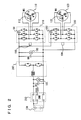
Fig. 2 represents an electrical system of a hybrid vehicle. -
Fig. 3 represents an example of a control system. -
Fig. 4 shows devices stored as a device being in error. -
Fig. 5 is a flowchart of a control configuration of a motor generator ECU. - An embodiment of the present invention will be described hereinafter with reference to the drawings. Hereinafter, the same elements have the same reference characters allotted, and their designation and function are also the same. Therefore, detailed description thereof will not be repeated.
- Referring to
Fig. 1 , a hybrid vehicle is mounted with anengine 100, afirst motor generator 110, asecond motor generator 120, apower split mechanism 130, aspeed reducer 140, and abattery 150. Although a hybrid vehicle will be described by way of example hereinafter, an electric automobile or a fuel cell car or the like may be employed instead of a hybrid vehicle. Moreover, a general vehicle having only an engine as the driving source may be employed. -
Engine 100 is controlled by an engine ECU 170.First motor generator 110 andsecond motor generator 120 are controlled by a motor generator ECU 172. Engine ECU 170 and motor generator ECU 172 operate based on a command value from a powermanagement control computer 174. Engine ECU 170, motor generator ECU 172 and powermanagement control computer 174 may be integrated. - The vehicle runs using the driving force from at least one of
engine 100 andsecond motor generator 120. In other words, one or both ofengine 100 andsecond motor generator 120 are automatically selected as the driving source according to the driving state. - For example, when the accelerator position is low and the vehicle speed is low, the hybrid vehicle runs using only
second motor generator 120 as the driving source.Engine 100 is stopped in this case, unless the need of power generation or the like requiresengine 100 to be driven. - In the case where the accelerator position is high, the vehicle speed is high, the remaining amount in
battery 150 is low, or the like,engine 100 is driven. Under such circumstances, the hybrid vehicle runs using onlyengine 100, or bothengine 100 andsecond motor generator 120 as the driving source. -
Engine 100 is an internal combustion engine. The crankshaft that is the output shaft rotates by the mixture gas of fuel and air burning in the combustion chamber. The exhaust gas output fromengine 100 is cleaned by acatalyst 102 to be discharged outside the vehicle. Catalyst 102 exhibits a cleaning effect by being warmed up to a specific temperature. The warming ofcatalyst 102 is carried out utilizing the heat of the exhaust gas. Catalyst 102 is, for example, a 3-way catalyst. -
Engine 100,first motor generator 110 andsecond motor generator 120 are connected viapower split mechanism 130. The motive power generated byengine 100 is split into two paths bypower split mechanism 130. One path is directed to driving afront wheel 160 viaspeed reducer 140. The other path is directed to drivingfirst motor generator 110 for generating power. -
First motor generator 110 is a three-phase alternating current electric rotating machine including a U-phase coil, a V-phase coil, and a W-phase coil.First motor generator 110 generates electric power using the motive power ofengine 100 that is split bypower split mechanism 130. The electric power generated byfirst motor generator 110 is used depending on the running state of the vehicle or the remaining amount of charge inbattery 150. For example, in the normal running mode, the electric power generated byfirst motor generator 110 is directly used as the electric power for drivingsecond motor generator 120. On the other hand, when SOC ofbattery 150 is lower than a predetermined value, the electric power generated byfirst motor generator 110 is converted from alternating current into direct current by an inverter that will be described afterwards. Thereafter, the voltage is adjusted by a converter that will be described afterwards and stored inbattery 150. - When
first motor generator 110 acts as a power generator,first motor generator 110 generates negative torque. As used herein, negative torque refers to such torque that becomes a load onengine 100. Whenfirst motor generator 110 receives power supply and acts as a motor,first motor generator 110 generates positive torque. As used herein, positive torque refers to such torque that does not become a load onengine 100, that is, such torque that assists in rotation ofengine 100. The same applies tosecond motor generator 120. -
Second motor generator 120 is a three-phase alternating current electric rotating machine including a U-phase coil, a V-phase coil, and a W-phase coil.Second motor generator 120 is driven by at least one of the electric power stored inbattery 150 and the electric power generated byfirst motor generator 110. - The driving force of
second motor generator 120 is transmitted tofront wheels 160 throughspeed reducer 140. Accordingly,second motor generator 120assists engine 100 or allows the vehicle to run with the driving force fromsecond motor generator 120. The rear wheels may be driven in place of or in addition tofront wheels 160. - At the time of regenerative braking of the hybrid vehicle,
second motor generator 120 is driven byfront wheels 160 throughspeed reducer 140, so thatsecond motor generator 120 operates as a power generator. Thus,second motor generator 120 operates as a regenerative brake that converts braking energy into electric power. The electric power generated bysecond motor generator 120 is stored inbattery 150. -
Power split mechanism 130 is formed of a planetary gear train including a sun gear, pinion gears, a carrier, and a ring gear. The pinion gears are engaged with the sun gear and the ring gear. The carrier supports the pinion gears such that they are rotatable on their own axes. The sun gear is coupled to the rotation shaft offirst motor generator 110. The carrier is coupled to the crankshaft ofengine 100. The ring gear is coupled to the rotation shaft ofsecond motor generator 120 andspeed reducer 140. -
Engine 100,first motor generator 110, andsecond motor generator 120 are coupled viapower split mechanism 130 formed of the planetary gear train, so that the rotational speeds ofengine 100,first motor generator 110, andsecond motor generator 120 have the relation represented by a straight line in a nomographic chart. -
Battery 150 is a battery pack configured such that a plurality of battery modules, each formed by integrating a plurality of battery cells, are connected in series. The voltage ofbattery 150 is, for example, about 200 V. A capacitor may be used in place of or in addition tobattery 150. - Referring to
Fig. 2 , an electrical system of the hybrid vehicle will be further described. Provided in the hybrid vehicle are aconverter 200, afirst inverter 210, asecond inverter 220, and a systemmain relay 230. -
Converter 200 includes a reactor, two npn transistors, and two diodes. The reactor has one end connected to the positive electrode side of each battery and the other end connected to a node between the two npn transistors. - The two npn transistors are connected in series. A diode is connected between the collector and the emitter of each npn transistor to allow current to flow from the emitter side to the collector side.
- As the npn transistor, an IGBT (Insulated Gate Bipolar Transistor) can be used, for example. In place of the npn transistor, a power switching element such as a power MOSFET (Metal Oxide Semiconductor Field-Effect Transistor) can be used.
- When the electric power discharged from
battery 150 is supplied tofirst motor generator 110 orsecond motor generator 120, the voltage is boosted byconverter 200. Conversely, when the electric power generated byfirst motor generator 110 orsecond motor generator 120 is to be supplied tobattery 150, the voltage is decreased byconverter 200. - A system voltage VH between
converter 200 and each inverter is detected by avoltage sensor 180. A voltage VL betweenbattery 150 andconverter 200 is detected by avoltage sensor 182. The signals representing the detection results fromvoltage sensor 180 andvoltage sensor 182 are sent tomotor generator ECU 172. -
First inverter 210 includes a U-phase arm, a V-phase arm, and a W-phase arm. The U-phase arm, the V-phase arm, and the W-phase arm are connected in parallel. The U-phase arm, the V-phase arm, and the W-phase arm each have two npn transistors connected in series. A diode is connected between the collector and the emitter of each npn transistor to allow current to flow from the emitter side to the collector side. Then, the node between the npn transistors in each arm is connected to the end different from aneutral point 112 of each coil offirst motor generator 110. -
First inverter 210 converts direct current supplied frombattery 150 into alternating current, which is supplied tofirst motor generator 110.First inverter 210 converts alternating current generated byfirst motor generator 110 into direct current. -
Second inverter 220 includes a U-phase arm, a V-phase arm, and a W-phase arm. The U-phase arm, the V-phase arm, and the W-phase arm are connected in parallel. The U-phase arm, the V-phase arm, and the W-phase arm each have two npn transistors connected in series. A diode is connected between the collector and the emitter of each npn transistor to allow current to flow from the emitter side to the collector side. Then, the node between the npn transistors in each arm is connected to the end different from aneutral point 122 of each coil ofsecond motor generator 120. -
Second inverter 220 converts direct current supplied frombattery 150 into alternating current and supplies the alternating current tosecond motor generator 120.Second inverter 220 converts alternating current generated bysecond motor generator 120 into direct current. -
Converter 200,first inverter 210, andsecond inverter 220 are controlled bymotor generator ECU 172. - In
first inverter 210 andsecond inverter 220 are provide acurrent sensor 191 and acurrent sensor 192, respectively.Current sensor 191 detects the input/output current offirst motor generator 110.Current sensor 192 detects the input/output current ofsecond motor generator 120. The signals representing the detected results ofcurrent sensor 191 andcurrent sensor 192 are applied tomotor generator ECU 172. - In addition to
current sensors temperature sensor 193 and atemperature sensor 194 are provided.Temperature sensor 193 detects the temperature offirst inverter 210.Temperature sensor 194 detects the temperature ofsecond inverter 220. The signals representing the detected results oftemperature sensors motor generator ECU 172. - System
main relay 230 switches the state betweenbattery 150 andconverter 200 to a connected state and a cut off state. When systemmain relay 230 is in an open state,battery 150 is cut off fromconverter 200. When systemmain relay 230 is in a closed state,battery 150 is connected toconverter 200. -
Motor generator ECU 172 will be described in further detail with reference toFig. 3 .Motor generator ECU 172 includes afirst CPU 310, asecond CPU 320, athird CPU 330, aRAM 340, and acommunication circuit 350. - By way of example,
voltage sensor 180,voltage sensor 182,current sensor 192,temperature sensor 193,temperature sensor 194,first CPU 310,second CPU 320 andcommunication circuit 350 constitute the control system ofsecond motor generator 120. The control system is not limited thereto. -
First CPU 310 includes an analog/digital converter 312. Analog/digital converter 312 converts an analog signal transmitted fromvoltage sensor 180,voltage sensor 182, andtemperature sensor 193 into a digital signal.First CPU 310 uses the signal transmitted fromvoltage sensor 180,voltage sensor 182, andtemperature sensor 193 to controlfirst inverter 210. For example,first CPU 310 generates a control signal to controlfirst inverter 210 based on signals transmitted fromvoltage sensor 180,voltage sensor 182, andtemperature sensor 193. - In the present embodiment,
second CPU 320 receives the signal generated byvoltage sensor 180,voltage sensor 182, andtemperature sensor 193 viafirst CPU 310 andcommunication circuit 350. -
Second CPU 320 includes an analog/digital converter 322. Analog/digital converter 322 converts an analog signal transmitted fromcurrent sensor 192 andtemperature sensor 194 into a digital signal.Second CPU 320 uses the signal transmitted fromvoltage sensor 180,voltage sensor 182,current sensor 192,temperature sensor 193, andtemperature sensor 194 to controlsecond inverter 220 that is the control subject.Second CPU 320 controls the second motor generator by controllingsecond inverter 220. For example,second CPU 320 generates a control signal to controlsecond inverter 220 based on the signal transmitted fromvoltage sensor 180,voltage sensor 182,current sensor 192,temperature sensor 193, andtemperature sensor 194. - As set forth above, the signal generated by
voltage sensor 180 is transmitted passing throughvoltage sensor 180, analog/digital converter 312,first CPU 310,communication circuit 350 andsecond CPU 320 in sequence. - The signal generated by
voltage sensor 182 is transmitted passing throughvoltage sensor 182, analog/digital converter 312,first CPU 310,communication circuit 350 andsecond CPU 320 in sequence. - The signal generated by
temperature sensor 193 is transmitted passing throughtemperature sensor 193, analog/digital converter 312,first CPU 310,communication circuit 350 andsecond CPU 320 in sequence. - The signal generated by
current sensor 192 is transmitted in sequence passing throughcurrent sensor 192, analog/digital converter 322, andsecond CPU 320 in sequence. - The signal generated by
temperature sensor 194 is transmitted passing throughtemperature sensor 194, analog/digital converter 322, andsecond CPU 320 in sequence. - Therefore, the control system includes five transmission paths through which signals are transmitted. The number of transmission paths corresponds to the number of sensors. The number of transmission paths is not limited thereto.
-
Third CPU 330 determines whether the control system is in error or not. For example,third CPU 330 determines whether the signal transmitted fromvoltage sensor 180,voltage sensor 182,current sensor 192,temperature sensor 193 andtemperature sensor 194 tosecond CPU 320 is in error or not. A determination is made that the transmitted signal is in error when the value represented by the transmitted signal is equal to or greater than an upper limit or less than or equal to a lower limit. In the case where a signal is not transmitted tosecond CPU 320, a determination is made that the signal is in error. The method of detecting whether the signal is in error is not limited thereto. -
Third CPU 330 determines that the control system is in error when a determination is made that the signal transmitted tosecond CPU 320 is in error. For example, when the duration of the determination of the signal being in error exceeds a predetermined time, a determination is made that the control system is in error. In the event of the control system being determined to be in error, a flag indicating that the control system is in error is turned ON to notify the ECUs other thanmotor generator ECU 172 as well as the computer that the control system is faulty. - Information indicating that the control system is in error is stored in
RAM 340 to notify a worker at a repair workshop or the like using the diagnosis tool about the control system being in error. A non-volatile memory other than a RAM may be employed to store such information. - When a determination is made that the control system is in error,
second CPU 320 executes a fail safe mode. For example, operation ofsecond inverter 220 is prohibited. The fail safe mode is not limited thereto. The fail safe mode may be executed to allow the hybrid vehicle to run only at a low speed. - In the case where a determination is made that the control system is in error,
third CPU 330 performs the step of determining whether each ofvoltage sensor 180,voltage sensor 182,current sensor 192,temperature sensor 193,temperature sensor 194,first CPU 310,second CPU 320, andcommunication circuit 350 is in error or not. Whether each of these devices is in error or not is determined without using signals transmitted from other devices. The method of detecting an error in each device can be carried out by the well-known common method. Therefore, details thereof will not be repeated here. Whether each ofvoltage sensor 180,voltage sensor 182,current sensor 192,temperature sensor 193,temperature sensor 194,first CPU 310,second CPU 320, andcommunication circuit 350 is in error or not may be determined using a plurality of CPUs.First CPU 310 andsecond CPU 320 may be set to carry out a self-diagnosis of whether in error or not. When an error is detected, a flag corresponding to each device is turned ON. - Among the devices determined to be in error, the device located most downstream in each signal transmission path is stored in
RAM 340 as the faulty device. For example, information indicating the faulty device is stored inRAM 340. A non-volatile memory other than the RAM may be used to store such information. - When a determination is made that
voltage sensor 180 is in error in the signal transmission path including, for example,voltage sensor 180, analog/digital converter 312,first CPU 310,communication circuit 350 andsecond CPU 320, as shown inFig. 4 , information indicating that the faulty device isvoltage sensor 180 is stored inRAM 340. When a determination is made thatvoltage sensor 180 and analog/digital converter 312 are faulty, information indicating that the faulty device is analog/digital converter 312 is stored inRAM 340. In this case, upon analog/digital converter 312 attaining a proper state by the repair offirst CPU 310, the information that the faulty device isvoltage sensor 180 will be stored. In the case where a determination is made thatcommunication circuit 350 is faulty, information indicating that the faulty device iscommunication circuit 350 is stored inRAM 340. - In a similar manner for the other transmission paths, information indicating the faulty device is stored in
RAM 340. - A control configuration of
motor generator ECU 172 will be described with reference toFig. 5 . - At step (hereinafter, step abbreviated as "S") 100, a determination is made as to whether the signal transmitted from
voltage sensor 180,voltage sensor 182,current sensor 192,temperature sensor 193, andtemperature sensor 194 is in error or not. When the transmitted signal is in error (YES at step S100), control proceeds to S102; otherwise (NO at S100), control returns to S100. - At S102, a determination that the control system is in error is provided. At S104, information that the control system is in error is stored.
- At S106, a determination is made as to whether each of
voltage sensor 180,voltage sensor 182,current sensor 192,temperature sensor 193,temperature sensor 194,first CPU 310,second CPU 320 andcommunication circuit 350 is in error or not. - At
S 108, the device located most downstream in the signal transmission path among the devices determined to be in error is stored as the faulty device. At S110, a fail safe mode is executed. - Thus, in the event of an error in a signal used by the control system, a determination is made that the control system is in error prior to performing the step of determining whether each of a plurality of devices through which the signal is transmitted is in error or not. Accordingly, the state of the control system being in error can be detected promptly. Following the determination of the control system being in error, the step of determining whether each of a plurality of devices transmitting the signal is in error or not is performed. Accordingly, the site with the error can be identified. Thus, an error in the control system can be detected promptly, and the site with the error can be identified.
- It should be understood that the embodiments disclosed herein are illustrative and non-restrictive in every respect. The scope of the present invention is defined by the terms of the claims, rather than the description set forth above, and is intended to include any modifications within the scope and meaning equivalent to the terms of the claims.
- 100 engine; 102 catalyst; 110 first motor generator; 120 second motor generator; 130 power split mechanism; 140 speed reducer; 150 battery; 160 front wheel; 170 engine ECU; 172 motor generator ECU; 180, 182 voltage sensor; 191, 192 current sensor; 193, 194 temperature sensor; 200 converter; 210 first inverter; 220 second inverter; 230 system main relay; 310 first CPU; 312 analog/digital converter; 320 second CPU; 322 analog/digital converter; 330 third CPU; 340 RAM; 350 communication circuit.
Claims (5)
- An error determination device of a control system using a signal transmitted by a plurality of devices (180, 182, 192, 193, 194, 310, 320, 350), comprising:a determination unit (330) determining whether said control system is in error or not, anda storage unit (340) storing that said control system is in error when a determination of said control system being in error is made ,said determination unit (330) configured todetermine whether a signal transmitted by said plurality of devices (180, 182, 192, 193, 194, 310, 320, 350) is in error or not,when a determination is made that the signal transmitted by said plurality of devices (180, 182, 192, 193, 194, 310, 320, 350) is in error, determine that said control system is in error, andwhen a determination is made that said control system is in error, determine whether each of said plurality of devices (180, 182, 192, 193, 194, 310, 320, 350) is in error or not.
- The error determination device of a control system according to claim 1, wherein
said signal is transmitted passing through said plurality of devices (180, 182, 192, 193, 194, 310, 320, 350) in sequence,
said storage unit (340) stores a device located most downstream in said signal transmission path among devices determined to be in error as the device in error. - The error determination device of a control system according to claim 1, wherein
said plurality of devices (180, 182, 192, 193, 194, 310, 320, 350) include a control device (320) using said signal,
said control device (320) executes a fail safe mode when a determination is made that said control system is in error. - An error determination method of a control system using a signal transmitted by a plurality of devices (180, 182, 192, 193, 194, 310, 320, 350), said method comprising the steps of:determining whether a signal transmitted by said plurality of devices (180, 182, 192, 193, 194, 310, 320, 350) is in error or not,when a determination is made that the signal transmitted by said plurality of devices (180, 182, 192, 193, 194, 310, 320, 350) is in error, determining that said control system is in error, andwhen a determination is made that said control system is in error, determining whether each of said plurality of devices (180, 182, 192, 193, 194, 310, 320, 350) is in error or not.
- An error determination device of a control system using a signal transmitted by a plurality of devices (180, 182, 192, 193, 194, 310, 320, 350), comprising:determination means (330) for determining whether said control system is in error or not, andstorage means (340) for storing that said control system is in error when a determination of said control system being in error is made,said determination means (330) configured todetermine whether a signal transmitted by said plurality of devices (180, 182, 192, 193, 194, 310, 320, 350) is in error or not,when a determination is made that the signal transmitted by said plurality of devices (180, 182, 192, 193, 194, 310, 320, 350) is in error, determine that said control system is in error, andwhen a determination is made that said control system is in error, determine whether each of said plurality of devices (180, 182, 192, 193, 194, 310, 320, 350) is in error or not.
Applications Claiming Priority (1)
| Application Number | Priority Date | Filing Date | Title |
|---|---|---|---|
| PCT/JP2010/051010 WO2011092805A1 (en) | 2010-01-27 | 2010-01-27 | Anomaly assessment device and anomaly assessment method of control system |
Publications (2)
| Publication Number | Publication Date |
|---|---|
| EP2530550A1 true EP2530550A1 (en) | 2012-12-05 |
| EP2530550A4 EP2530550A4 (en) | 2013-12-25 |
Family
ID=44318818
Family Applications (1)
| Application Number | Title | Priority Date | Filing Date |
|---|---|---|---|
| EP10844571.9A Withdrawn EP2530550A4 (en) | 2010-01-27 | 2010-01-27 | ANOMALY TESTING DEVICE AND ANOMALY TEST PROCEDURE FOR A CONTROL SYSTEM |
Country Status (5)
| Country | Link |
|---|---|
| US (1) | US8762791B2 (en) |
| EP (1) | EP2530550A4 (en) |
| JP (1) | JP5299525B2 (en) |
| CN (1) | CN102713778B (en) |
| WO (1) | WO2011092805A1 (en) |
Cited By (1)
| Publication number | Priority date | Publication date | Assignee | Title |
|---|---|---|---|---|
| WO2019020900A1 (en) * | 2017-07-25 | 2019-01-31 | Continental Automotive France | Method for analysing the operation of an anti-pollution system for a motor vehicle |
Families Citing this family (7)
| Publication number | Priority date | Publication date | Assignee | Title |
|---|---|---|---|---|
| EP2816364B1 (en) * | 2013-06-20 | 2023-09-27 | Abb Ag | Proof test arrangement and proof test method for a switchgear |
| CN103472309B (en) * | 2013-09-27 | 2015-10-14 | 山东智洋电气有限公司 | Insulation Inspection Device for Direct-Current System and method |
| US9568089B2 (en) * | 2014-03-21 | 2017-02-14 | Flextronics Ap, Llc | Smart solenoid for controlling fluid flow |
| KR101558383B1 (en) * | 2014-05-08 | 2015-10-07 | 현대자동차 주식회사 | Daignosing method for smart sensor or actuator of vehicle |
| JP2016125436A (en) * | 2015-01-07 | 2016-07-11 | 日立オートモティブシステムズ株式会社 | Engine control system |
| JP5968501B1 (en) * | 2015-06-01 | 2016-08-10 | 三菱電機株式会社 | In-vehicle electronic control unit |
| US12189461B2 (en) | 2022-12-09 | 2025-01-07 | Baker Hughes Holdings Llc | Enhanced transducer fault detection |
Family Cites Families (16)
| Publication number | Priority date | Publication date | Assignee | Title |
|---|---|---|---|---|
| US4404514A (en) * | 1981-08-24 | 1983-09-13 | General Instrument Corporation | Fault detection system as for locating faulty connections in a cable television system |
| US5163056A (en) * | 1987-10-01 | 1992-11-10 | Kabushiki Kaisha Komatsu Seisakusho | Apparatus for carrying out serial control |
| JP2536551B2 (en) | 1987-10-19 | 1996-09-18 | 横河電機株式会社 | Process error cause diagnosis method |
| JP3243005B2 (en) | 1992-08-31 | 2002-01-07 | 東芝トランスポートエンジニアリング株式会社 | Master control device |
| JPH06137909A (en) | 1992-10-26 | 1994-05-20 | Hitachi Ltd | Plant monitoring equipment |
| JP3953542B2 (en) | 1995-12-13 | 2007-08-08 | 株式会社デンソー | Electronic control unit |
| JPH11288311A (en) | 1998-04-03 | 1999-10-19 | Sony Corp | Measuring equipment |
| SE511967C2 (en) | 1998-09-10 | 1999-12-20 | Mecel Ab | Method and system for diagnosing composite distributed systems, preferably implemented in vehicles |
| JP2001243082A (en) | 2000-02-25 | 2001-09-07 | Denso Corp | Electronic control device and recording medium |
| JP3805648B2 (en) * | 2001-06-14 | 2006-08-02 | 三菱電機株式会社 | Engine intake air amount control device |
| DE10161631B4 (en) * | 2001-12-14 | 2004-01-22 | Siemens Ag | Method for correcting the start of sampling a serial bit sequence of an output signal of a filter |
| JP4350931B2 (en) | 2002-02-12 | 2009-10-28 | 株式会社デンソー | Vehicle abnormality diagnosis apparatus and abnormality diagnosis method |
| JP4082306B2 (en) * | 2003-08-08 | 2008-04-30 | 三菱ふそうトラック・バス株式会社 | Fault diagnosis device |
| JP2005291102A (en) | 2004-03-31 | 2005-10-20 | Fuji Heavy Ind Ltd | Failure diagnosis device for fuel system |
| JP2006057523A (en) | 2004-08-19 | 2006-03-02 | Denso Corp | Engine control system abnormality diagnosis device |
| JP4420944B2 (en) * | 2007-07-27 | 2010-02-24 | 三菱電機株式会社 | In-vehicle engine controller |
-
2010
- 2010-01-27 WO PCT/JP2010/051010 patent/WO2011092805A1/en not_active Ceased
- 2010-01-27 CN CN201080062119.1A patent/CN102713778B/en active Active
- 2010-01-27 US US13/575,498 patent/US8762791B2/en active Active
- 2010-01-27 EP EP10844571.9A patent/EP2530550A4/en not_active Withdrawn
- 2010-01-27 JP JP2011551613A patent/JP5299525B2/en active Active
Cited By (5)
| Publication number | Priority date | Publication date | Assignee | Title |
|---|---|---|---|---|
| WO2019020900A1 (en) * | 2017-07-25 | 2019-01-31 | Continental Automotive France | Method for analysing the operation of an anti-pollution system for a motor vehicle |
| FR3069573A1 (en) * | 2017-07-25 | 2019-02-01 | Continental Automotive France | METHOD FOR ANALYZING THE OPERATION OF AN ANTI-POLLUTION SYSTEM OF A MOTOR VEHICLE |
| CN111094715A (en) * | 2017-07-25 | 2020-05-01 | 法国大陆汽车公司 | Method for analyzing the operation of a decontamination system of a motor vehicle |
| CN111094715B (en) * | 2017-07-25 | 2022-04-19 | 法国大陆汽车公司 | Method for analyzing the operation of a decontamination system of a motor vehicle |
| US11525382B2 (en) | 2017-07-25 | 2022-12-13 | Continental Automotive France | Method for analysing the operation of an anti-pollution system for a motor vehicle |
Also Published As
| Publication number | Publication date |
|---|---|
| US8762791B2 (en) | 2014-06-24 |
| CN102713778A (en) | 2012-10-03 |
| JP5299525B2 (en) | 2013-09-25 |
| US20120297235A1 (en) | 2012-11-22 |
| JPWO2011092805A1 (en) | 2013-05-30 |
| CN102713778B (en) | 2014-02-12 |
| WO2011092805A1 (en) | 2011-08-04 |
| EP2530550A4 (en) | 2013-12-25 |
Similar Documents
| Publication | Publication Date | Title |
|---|---|---|
| US8762791B2 (en) | Error determination device and error determination method of control system | |
| EP3162608B1 (en) | Limp-home mode for hybrid vehicle | |
| EP2058935A1 (en) | Motor drive device | |
| EP2743150B1 (en) | Vehicle, vehicle control method and vehicle control device | |
| JP2009247052A (en) | Rotating electrical machine control system and vehicle driving system | |
| JP5590157B2 (en) | Vehicle, vehicle control method, and vehicle control apparatus | |
| US20140288744A1 (en) | Control apparatus for vehicle | |
| JP2016101032A (en) | Vehicle and control method thereof | |
| JP5133609B2 (en) | Vehicle and control method thereof | |
| CN108736718A (en) | Driving device | |
| JP2013207831A (en) | Electric vehicle | |
| WO2015059555A1 (en) | Control device for vehicle | |
| JP2012075228A (en) | Apparatus for diagnosing cooling system | |
| US8718851B2 (en) | Control device for hybrid vehicle, control method for hybrid vehicle, and hybrid vehicle | |
| US10391863B2 (en) | Electrically driven vehicle | |
| JP5270314B2 (en) | System control unit | |
| JP5834452B2 (en) | Cooling system abnormality judgment device | |
| JP2014189252A (en) | Vehicle controller | |
| JP5136205B2 (en) | POWER OUTPUT DEVICE, ITS CONTROL METHOD, AND VEHICLE | |
| WO2012111068A1 (en) | Vehicle, and vehicle control method | |
| JP2008068775A (en) | POWER OUTPUT DEVICE, ITS CONTROL METHOD, AND VEHICLE | |
| JP2010067571A (en) | Device for determining abnormal conditin of cooling fan | |
| WO2012105018A1 (en) | Vehicle and method for controlling vehicle |
Legal Events
| Date | Code | Title | Description |
|---|---|---|---|
| PUAI | Public reference made under article 153(3) epc to a published international application that has entered the european phase |
Free format text: ORIGINAL CODE: 0009012 |
|
| 17P | Request for examination filed |
Effective date: 20120508 |
|
| AK | Designated contracting states |
Kind code of ref document: A1 Designated state(s): AT BE BG CH CY CZ DE DK EE ES FI FR GB GR HR HU IE IS IT LI LT LU LV MC MK MT NL NO PL PT RO SE SI SK SM TR |
|
| RAP1 | Party data changed (applicant data changed or rights of an application transferred) |
Owner name: TOYOTA JIDOSHA KABUSHIKI KAISHA |
|
| DAX | Request for extension of the european patent (deleted) | ||
| A4 | Supplementary search report drawn up and despatched |
Effective date: 20131121 |
|
| RIC1 | Information provided on ipc code assigned before grant |
Ipc: F02D 41/26 20060101ALI20131115BHEP Ipc: F02D 45/00 20060101ALI20131115BHEP Ipc: B60L 11/12 20060101ALI20131115BHEP Ipc: B60L 11/18 20060101ALI20131115BHEP Ipc: G05B 23/02 20060101AFI20131115BHEP Ipc: F02N 11/04 20060101ALI20131115BHEP Ipc: B60K 6/445 20071001ALI20131115BHEP Ipc: F02D 41/22 20060101ALI20131115BHEP Ipc: G01M 17/007 20060101ALI20131115BHEP Ipc: F02N 11/10 20060101ALI20131115BHEP |
|
| 17Q | First examination report despatched |
Effective date: 20160502 |
|
| STAA | Information on the status of an ep patent application or granted ep patent |
Free format text: STATUS: EXAMINATION IS IN PROGRESS |
|
| STAA | Information on the status of an ep patent application or granted ep patent |
Free format text: STATUS: THE APPLICATION IS DEEMED TO BE WITHDRAWN |
|
| 18D | Application deemed to be withdrawn |
Effective date: 20180215 |
|
| RIC1 | Information provided on ipc code assigned before grant |
Ipc: B60L 11/18 20060101ALI20131115BHEP Ipc: F02N 11/04 20060101ALI20131115BHEP Ipc: G01M 17/007 20060101ALI20131115BHEP Ipc: F02D 41/22 20060101ALI20131115BHEP Ipc: G05B 23/02 20060101AFI20131115BHEP Ipc: B60L 11/12 20060101ALI20131115BHEP Ipc: F02D 45/00 20060101ALI20131115BHEP Ipc: F02D 41/26 20060101ALI20131115BHEP Ipc: B60K 6/445 20071001ALI20131115BHEP Ipc: F02N 11/10 20060101ALI20131115BHEP |