JP2005291102A - Failure diagnosis device for fuel system - Google Patents
Failure diagnosis device for fuel system Download PDFInfo
- Publication number
- JP2005291102A JP2005291102A JP2004108096A JP2004108096A JP2005291102A JP 2005291102 A JP2005291102 A JP 2005291102A JP 2004108096 A JP2004108096 A JP 2004108096A JP 2004108096 A JP2004108096 A JP 2004108096A JP 2005291102 A JP2005291102 A JP 2005291102A
- Authority
- JP
- Japan
- Prior art keywords
- diagnosis
- characteristic
- abnormality detection
- abnormality
- detection determination
- Prior art date
- Legal status (The legal status is an assumption and is not a legal conclusion. Google has not performed a legal analysis and makes no representation as to the accuracy of the status listed.)
- Pending
Links
Images


Landscapes
- Electrical Control Of Air Or Fuel Supplied To Internal-Combustion Engine (AREA)
- Combined Controls Of Internal Combustion Engines (AREA)
Abstract
【課題】燃料系システムに故障が生じた場合、故障部位を特定できるようにする。
【解決手段】燃料系システムの故障診断においてリッチ異常が検出されたとき、吸入空気量センサ9の特性診断異常検出判定レベルを通常のK1からK2の狭いレベルに切換える(S3)。次いで運転領域が診断領域Aに有るか否かを調べ(S3)、診断領域Aにあるとき吸入空気量センサ9の出力値V1と特性診断異常検出判定レベルK2とを比較し(S4)、V1≧K2のとき吸入空気量センサ9の異常と判定する(S6)。
【選択図】図2
When a failure occurs in a fuel system, it is possible to identify a failure part.
When a rich abnormality is detected in a failure diagnosis of a fuel system, a characteristic diagnosis abnormality detection determination level of an intake air amount sensor is switched from a normal K1 to a narrow level of K2 (S3). Next, it is checked whether or not the operation region is in the diagnosis region A (S3). When the operation region is in the diagnosis region A, the output value V1 of the intake air amount sensor 9 is compared with the characteristic diagnosis abnormality detection determination level K2 (S4). When ≧ K2, it is determined that the intake air amount sensor 9 is abnormal (S6).
[Selection] Figure 2
Description
本発明は、燃料系システムの異常を検出したときは、更に吸気系センサの異常を検出する燃料系システムの故障診断装置に関する。 The present invention relates to a failure diagnosis apparatus for a fuel system that detects an abnormality of an intake system sensor when an abnormality of the fuel system is detected.
一般に、エンジンの燃料系システムにおいては、排気通路中に臨まされている空燃比センサで検出した実際の空燃比が目標空燃比に収束するように燃料噴射量をフィードバック制御している。燃料系システムに異常が発生した場合、燃料噴射量を正しく制御することができず、空燃比が悪化して排気エミッションの増大を招く。 In general, in a fuel system of an engine, the fuel injection amount is feedback-controlled so that the actual air-fuel ratio detected by an air-fuel ratio sensor facing the exhaust passage converges to a target air-fuel ratio. When an abnormality occurs in the fuel system, the fuel injection amount cannot be controlled correctly, and the air-fuel ratio deteriorates, leading to an increase in exhaust emission.
そのため、燃料系システムには異常発生を検出する故障診断機能が備えられている。ところで、空燃比は気筒に供給される空気量と気筒に供給する燃料量との比であるため、燃料系システムで異常が検出された場合、すなわち、燃料噴射量を増量(減量)しているにも拘わらず、空燃比センサでは相変わらず、リーン(リッチ)が検出されている場合、故障の原因は燃料系と吸気系との双方が考えられる。 For this reason, the fuel system is provided with a failure diagnosis function for detecting the occurrence of an abnormality. By the way, since the air-fuel ratio is a ratio of the amount of air supplied to the cylinder and the amount of fuel supplied to the cylinder, when an abnormality is detected in the fuel system, that is, the fuel injection amount is increased (decreased). Nevertheless, when the air-fuel ratio sensor is still lean (rich) is detected, the cause of the failure is considered to be both the fuel system and the intake system.
そのため、例えば、第2681566号公報(特開平5−163982号公報)には、基本燃料噴射量とエンジン回転数とに基づいて複数に区分した運転領域から、吸入空気量レベルがほぼ同一の2つの運転領域を設定し、この両運転領域において設定される空燃比学習値を比較し、両者の空燃比学習値の偏差が所定値異常のときは、吸入空気量センサの検出誤差ではなく、燃料系が原因で空燃比に大きなずれが生じていると判定し、燃料系の故障診断を実行する技術が開示されている。
しかし、特許文献1に開示されている技術では、故障診断に際し、2つの学習値を比較して、吸入空気量センサの誤検出による異常か否かを調べているにすぎず、吸入空気量センサが故障しているかどうかを特定するものではない。
However, in the technique disclosed in
通常、故障診断は、燃料系システム以外に、吸気系システムにおいても行っている。しかし、燃料系システムが異常と診断された場合は、燃料系システムの異常による他のシステムの誤診断を防止するために、他のシステムの故障診断をも停止する等の処理が行われる。 Usually, failure diagnosis is performed not only in the fuel system but also in the intake system. However, when the fuel system is diagnosed as abnormal, processing such as stopping other system failure diagnosis is performed in order to prevent misdiagnosis of the other system due to the abnormality of the fuel system.
この場合、燃料系システムの故障診断は、吸気系システムの故障診断に比し、検出範囲が広いので、燃料系システム異常と診断された場合、吸気系システムもその範疇に含まれることになる。そのため、燃料系システムの異常と診断された場合は、吸気系システムに故障原因が存在する場合であっても、その故障部品を特定することなく、システムが停止され、或いは故障診断が停止されてしまう。 In this case, the failure diagnosis of the fuel system has a wider detection range than the failure diagnosis of the intake system, and therefore when the fuel system abnormality is diagnosed, the intake system is included in the category. For this reason, if a malfunction of the fuel system is diagnosed, even if there is a failure cause in the intake system, the system is stopped or the failure diagnosis is stopped without specifying the failed part. End up.
その結果、例えばディーラのサービスステーション等において、故障部品を特定しようとする場合、故障原因を再度探究しなければならず、煩雑な作業が強いられるという問題がある。 As a result, for example, when trying to identify a faulty part in a dealer service station or the like, there is a problem that the cause of the fault must be searched again, and complicated work is forced.
本発明は、上記事情に鑑み、燃料系システムに故障が生じた場合、故障部品を特定することのできる吸気系システムの故障診断装置を提供することを目的とする。 In view of the above circumstances, an object of the present invention is to provide a failure diagnosis device for an intake system that can identify a failed component when a failure occurs in a fuel system.
上記目的を達成するため本発明による燃料系システムの故障診断装置は、燃料系システムの故障診断で異常が検出されたとき吸気系センサの出力特性を診断する吸気系センサ特性診断実行手段を備え、上記吸気系センサ特性診断実行手段は、故障診断を実行する診断領域を設定する診断領域設定手段と、上記出力特性と比較する特性診断異常検出レベルを設定する特性診断異常検出判定レベル設定手段と、上記診断領域と上記特性診断異常検出レベルとに基づいて上記吸気系センサの出力特性の異常の有無を判定する異常判定手段とを備えることを特徴とする。 In order to achieve the above object, a failure diagnosis apparatus for a fuel system according to the present invention comprises an intake system sensor characteristic diagnosis execution means for diagnosing an output characteristic of an intake system sensor when an abnormality is detected in the failure diagnosis of the fuel system. The intake system sensor characteristic diagnosis execution means includes a diagnosis area setting means for setting a diagnosis area for executing failure diagnosis, a characteristic diagnosis abnormality detection determination level setting means for setting a characteristic diagnosis abnormality detection level to be compared with the output characteristics, And an abnormality determining means for determining whether or not there is an abnormality in the output characteristics of the intake system sensor based on the diagnosis area and the characteristic diagnosis abnormality detection level.
本発明によれば、燃料系システムに故障が生じた場合、吸気系センサが故障原因かどうかを特定するので、例えばディーラのサービスステーション等では、少なくとも吸気系センサの故障調べる必要が無くなり、点検作業の簡素化を実現することができる。 According to the present invention, when a failure occurs in the fuel system, it is determined whether or not the intake system sensor is the cause of the failure. For example, at a dealer service station, it is not necessary to investigate at least the failure of the intake system sensor. Can be simplified.
以下、図面に基づいて本発明の一形態を説明する。図1〜図7に本発明の第1形態を示す。図1に燃料系システムの全体構成図を示す。 Hereinafter, an embodiment of the present invention will be described with reference to the drawings. 1 to 7 show a first embodiment of the present invention. FIG. 1 shows the overall configuration of the fuel system.
同図の符号1はエンジンで、エンジン1の吸気ポート1aに吸気マニホルド2を介して吸気通路3が連通され、この吸気通路3の最上流側にエアクリーナ(図示せず)が設けられている。又、吸気通路3の中途にスロットル弁4が介装され、このスロットル弁4の下流側に、吸気マニホルド2の集合部を接続するエアチャンバ5が形成されている。更に、吸気マニホルド2に、噴射方向を吸気ポート1a側に指向するインジェクタ6が固設されている。一方、エンジン1の排気ポート1bに排気通路7が連通され、この排気通路7の中途に触媒8が介装されている。尚、排気通路7の最下流にはマフラ(図示せず)が接続されている。
又、吸気通路3の上流側に吸気系センサの一例である吸入空気量センサ9が臨まされている。一方、排気通路7に配設されている触媒8の上流に、排ガス中の空燃比に比例した電圧を出力し、或いは排気ガス中の空燃比のリッチ/リーンを検出して電圧値を反転させる空燃比センサ10が配設されている。尚、符号12は点火プラグである。
An intake air amount sensor 9, which is an example of an intake system sensor, faces the upstream side of the
符号20はマイクロコンピュータ等からなる電子制御装置(ECU)で、入力側に、燃料系システムを制御するパラメータを検出する手段として、吸入空気量センサ9、空燃比センサ10、クランク軸等の回転からエンジン回転数を検出する回転数センサ13、スロットル弁4の開度を検出するスロットル開度センサ14等が接続されている。
ECU20は、各センサ・スイッチ類から出力される情報に基づき空燃比制御、点火時期制御等の各種制御を行なうと共に、所定運転領域において燃料系システムの故障診断を行う。更に、燃料系システムの異常が検出されたときは、吸気系システムを構成する部品の代表である吸入空気量センサ9の故障診断を行う。尚、吸入空気量センサ9の故障診断は、吸気系システムの故障診断の際に別途実施されるが、燃料系システム異常検出後の吸入空気量センサ9の故障診断は、より厳しい基準で行われる。 The ECU 20 performs various controls such as air-fuel ratio control and ignition timing control based on information output from each sensor / switch, and performs failure diagnosis of the fuel system in a predetermined operation region. Further, when an abnormality of the fuel system is detected, a failure diagnosis of the intake air amount sensor 9, which is a representative part constituting the intake system, is performed. The failure diagnosis of the intake air amount sensor 9 is separately performed at the time of the failure diagnosis of the intake system, but the failure diagnosis of the intake air amount sensor 9 after the abnormality detection of the fuel system is performed on a stricter standard. .
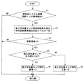
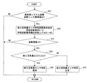
ECU20で実行される燃料系システム異常検出後の吸入空気量センサ9の故障診断は、具体的には、図2に示す吸入空気量センサ特性診断ルーチンに従って処理される。
Specifically, the failure diagnosis of the intake air amount sensor 9 after the abnormality detection of the fuel system executed by the
先ず、ステップS1では、燃料系システムの故障診断においてリッチ異常が検出されたか否かを調べる。燃料系システムの故障診断は、所定の運転領域において、空燃比センサ10で検出した空燃比に基づいて行う。空燃比センサ10が空燃比リーンを検出した場合、空燃比フィードバック制御では、当然、空燃比をリッチ補正する制御が行われる。しかし、空燃比をリッチ補正しても、空燃比センサ10で検出する空燃比が依然としてリーンの場合、空燃比フィードバック制御では、空燃比を更にリッチ方向へ補正する補正係数が設定される。その結果、空燃比フィードバック補正係数は、リッチ側上限値に貼り付いた状態となり、それ以上の制御が出来なくなる。
First, in step S1, it is checked whether or not a rich abnormality is detected in the failure diagnosis of the fuel system. The failure diagnosis of the fuel system is performed based on the air-fuel ratio detected by the air-
燃料系システムの故障診断では、例えば空燃比フィードバック補正係数がリッチ側に貼り付いた状態が設定時間継続している場合、リッチ異常と判定する。 In the failure diagnosis of the fuel system, for example, when the state where the air-fuel ratio feedback correction coefficient is stuck on the rich side continues for a set time, it is determined that the rich abnormality has occurred.
ステップS1では、リッチ異常か否かを、燃料系システムの故障診断において設定されるリッチ異常フラグの値を参照することで判断する。図5(a)に示すように、リッチ異常フラグは正常時は0、異常時は1にセットされる。そして、リッチ異常フラグ=1の異常時はステップS2へ進み、又、リッチ異常フラグ=0の正常時はそのままルーチンを抜ける。 In step S1, it is determined by referring to the value of the rich abnormality flag set in the failure diagnosis of the fuel system whether or not there is a rich abnormality. As shown in FIG. 5A, the rich abnormality flag is set to 0 when normal and 1 when abnormal. When the rich abnormality flag = 1 is abnormal, the process proceeds to step S2, and when the rich abnormality flag = 0 is normal, the routine is directly exited.
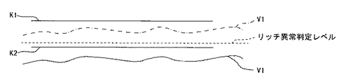
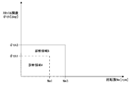
ステップS2へ進むと、吸入空気量センサ9の出力異常を判定する特性診断条件を設定する。特性診断条件として本形態では、通常の吸気系システムの故障診断を行う際に設定されている特性診断異常検出判定レベルK1[V]をK2[V]に設定する(図5(b)参照)。 In step S2, characteristic diagnosis conditions for determining an output abnormality of the intake air amount sensor 9 are set. In this embodiment, the characteristic diagnosis condition is set to K2 [V], which is a characteristic diagnosis abnormality detection determination level K1 [V] that is set when a failure diagnosis of a normal intake system is performed (see FIG. 5B). .
図3に示すように、新たに設定される特性診断異常検出判定レベルK2は、通常の吸気系システムの故障診断を行う際の特性診断異常検出判定レベルK1よりも低い値に設定されている。従って、燃料系システムの異常と診断されたときは、より厳しい判定レベル(K2)で吸入空気量センサ9の出力異常を検出することになる。 As shown in FIG. 3, the newly set characteristic diagnosis abnormality detection determination level K2 is set to a value lower than the characteristic diagnosis abnormality detection determination level K1 when performing a normal diagnosis of the intake system. Therefore, when an abnormality of the fuel system is diagnosed, an abnormality in the output of the intake air amount sensor 9 is detected with a stricter judgment level (K2).
ところで、通常の吸気系システムの故障診断の際に設定する特性診断異常検出判定レベルK1は、基準電圧に、センサ公差、回路公差等の個体差によるばらつきと、温度特性、制御公差等によるシステム制御上のばらつきとを考慮した値を加算することで設定されている。 By the way, the characteristic diagnosis abnormality detection determination level K1 set at the time of failure diagnosis of a normal intake system system is a system control based on variations due to individual differences such as sensor tolerance, circuit tolerance, etc., temperature characteristics, control tolerance, etc. It is set by adding a value considering the above variation.
従って、図3に示すように、特性診断異常検出判定レベルK1は、予め設定したリッチ異常判定レベルよりも緩い値に設定されている。一方、特性診断異常検出判定レベルK2は、上述したシステム制御上のばらつきを考慮せず、基準電圧に、個体差によるばらつきを考慮した値を加算しただけであるため、リッチ異常判定レベルと同じか、やや厳しい値に設定されている。 Therefore, as shown in FIG. 3, the characteristic diagnosis abnormality detection determination level K1 is set to a value that is looser than a preset rich abnormality determination level. On the other hand, the characteristic diagnosis abnormality detection determination level K2 is the same as the rich abnormality determination level because the above-described variation in system control is not considered and only a value considering variation due to individual differences is added to the reference voltage. It is set to a somewhat severe value.
次いで、ステップS3へ進み、診断領域(運転領域)が予め設定した診断領域Aに有るか否かを調べる。この診断領域Aは、通常の吸気系システムの故障診断を行う際に設定される診断領域(例えば、アイドル運転領域)と同一である。 Subsequently, it progresses to step S3 and it is investigated whether a diagnostic area | region (operation area | region) exists in the diagnostic area | region A set beforehand. This diagnosis area A is the same as a diagnosis area (for example, an idle operation area) that is set when a failure diagnosis of a normal intake system is performed.
図4に示すように、診断領域Aは、回転数センサ13で検出したエンジン回転数Neとエンジン負荷の一例であるスロットル開度センサ14で検出したスロットル開度θthとに基づいて判断する。尚、エンジン負荷を検出するバラメータとしては、スロットル開度θth以外に、アクセル開度や吸入管圧力等が有る。
As shown in FIG. 4, the diagnosis region A is determined based on the engine speed Ne detected by the speed sensor 13 and the throttle opening θth detected by the
そして、エンジン回転数Neが予め設定した領域判定回転数Ne1以下で、且つスロットル開度θthが予め設定した領域判定開度θth1以下のとき(Ne≦Ne1、且つθth≦θth1)、診断領域=Aと判定し、ステップS4へ進む。一方、エンジン回転数Neが予め設定した領域判定回転数Ne1より高いとき(Ne>Ne1)、或いは(及び)スロットル開度θthが予め設定した領域判定開度θth1より高いとき(θth>θth1)、診断領域から外れているため、ルーチンを抜ける。 When the engine speed Ne is equal to or smaller than a predetermined region determination rotational speed Ne1 and the throttle opening θth is equal to or smaller than a predetermined region determination opening θth1 (Ne ≦ Ne1 and θth ≦ θth1), the diagnosis region = A And the process proceeds to step S4. On the other hand, when the engine speed Ne is higher than the preset area determination speed Ne1 (Ne> Ne1), or (and) when the throttle opening degree θth is higher than the preset area determination opening degree θth1 (θth> θth1). The routine exits because it is out of the diagnostic area.
次いで、ステップS4へ進むと、吸入空気量センサ9の出力値V1と特性診断異常検出判定レベルK2とを比較する。そして、V1<K2のときは、ステップS5へ分岐し、吸入空気量センサ9の出力特性は正常であると判定し、特性診断正常異常判定フラグをクリア(=0)して、ルーチンを抜ける。一方、V1≧K2のときは、ステップS6へ進み、吸入空気量センサ9の出力特性が異常であると判定し、特性診断正常異常判定フラグをセット(=1)して、ルーチンを抜ける(図5(c)参照)。 Next, in step S4, the output value V1 of the intake air amount sensor 9 is compared with the characteristic diagnosis abnormality detection determination level K2. When V1 <K2, the process branches to step S5, where it is determined that the output characteristic of the intake air amount sensor 9 is normal, the characteristic diagnosis normal / abnormal determination flag is cleared (= 0), and the routine is exited. On the other hand, when V1 ≧ K2, the process proceeds to step S6, where it is determined that the output characteristic of the intake air amount sensor 9 is abnormal, the characteristic diagnosis normal / abnormal determination flag is set (= 1), and the routine is exited (FIG. 5). 5 (c)).
上述したように、特性診断異常検出判定レベルK2は、通常の吸気系システムの故障診断の際に設定する特性診断異常検出判定レベルK1よりも低い値に設定されている。又、このときの診断領域Aは、通常の吸気系システムの故障診断を行う際の診断領域と同一に設定されている。 As described above, the characteristic diagnosis abnormality detection determination level K2 is set to a value lower than the characteristic diagnosis abnormality detection determination level K1 set at the time of failure diagnosis of a normal intake system. In addition, the diagnosis area A at this time is set to be the same as the diagnosis area when performing a failure diagnosis of a normal intake system.
従って、図3に一点鎖線で示すように、特性診断異常検出判定レベルK1のときは異常を検出することのできなかった吸入空気量センサ9の出力値V1であっても、特性診断異常検出判定レベルK1に設定されることにより、吸入空気量センサ9の出力特性が異常であると判定される。一方、同図に実線で示すように、吸入空気量センサ9の出力値V1が特性診断異常検出判定レベルK1以下の場合は、当然、吸入空気量センサ9の出力特性は正常であると判定される。 Therefore, as indicated by the one-dot chain line in FIG. 3, even if the output value V1 of the intake air amount sensor 9 has not been able to detect an abnormality at the characteristic diagnosis abnormality detection determination level K1, the characteristic diagnosis abnormality detection determination By setting the level to K1, it is determined that the output characteristic of the intake air amount sensor 9 is abnormal. On the other hand, as shown by the solid line in the figure, when the output value V1 of the intake air amount sensor 9 is equal to or lower than the characteristic diagnosis abnormality detection determination level K1, it is naturally determined that the output characteristic of the intake air amount sensor 9 is normal. The
尚、上述したように、燃料系システムの故障診断においてリッチ異常が検出されている状態は、吸入空気量センサ9は空燃比リーンを検出しているということであり、従って、吸入空気量センサ9の故障により、燃料増量しても空燃比リーンの状態が継続されている状態は、実際の吸入空気量に対して吸入空気量センサ9の出力値V1が過大であると云うことである。 As described above, the state where the rich abnormality is detected in the failure diagnosis of the fuel system is that the intake air amount sensor 9 detects the air-fuel ratio lean. The state in which the air-fuel ratio lean state is maintained even if the amount of fuel is increased due to the failure in this means that the output value V1 of the intake air amount sensor 9 is excessive with respect to the actual intake air amount.
従って、特性診断異常検出判定レベルK1を特性診断異常検出判定レベルK2に下げることで、燃料系システムの故障診断においてリッチ異常が検出されている状態での吸入空気量センサ9の出力特性異常を容易に検出することができる。 Therefore, by lowering the characteristic diagnosis abnormality detection determination level K1 to the characteristic diagnosis abnormality detection determination level K2, the output characteristic abnormality of the intake air amount sensor 9 in the state where the rich abnormality is detected in the failure diagnosis of the fuel system can be easily performed. Can be detected.
そして、吸入空気量センサ9の出力特性異常と検出されたときは、インジェクタ5や燃料ポンプ等を代表とする燃料供給系の故障ではない。又、他のシステムの故障診断に対しては、影響のない範囲で故障診断を継続することができる。
When it is detected that the output characteristic of the intake air amount sensor 9 is abnormal, it is not a failure of the fuel supply system represented by the
又、燃料系システムの異常が検出された場合、吸入空気量センサ9に故障原因が有るか否かが診断されるので、ディーラのサービスステーション等では、少なくとも吸入空気量センサ9の故障を調べる必要がなくなり、点検作業を簡素化することができる。 Further, when an abnormality in the fuel system is detected, it is diagnosed whether or not there is a failure cause in the intake air amount sensor 9, so it is necessary to check at least the failure of the intake air amount sensor 9 in a dealer service station or the like. The inspection work can be simplified.
ところで、図2の吸入空気量センサ特性診断ルーチンでは、燃料系システムの故障診断においてリッチ異常が検出された場合について説明したが、リーン異常が検出された場合にも、吸気系システムの故障診断を行う。 Incidentally, in the intake air amount sensor characteristic diagnosis routine of FIG. 2, the case where the rich abnormality is detected in the fuel system failure diagnosis has been described. However, even when the lean abnormality is detected, the intake system failure diagnosis is performed. Do.
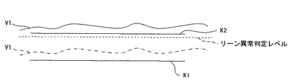
以下、リーン異常が検出されたときの、吸入空気量センサ9の故障診断について簡単に説明する。先ず、リーン異常フラグの値を参照して、正常時を示す0から異常時を示す1に切り替った場合(図6(a)参照)、通常の吸気系システムの故障診断を行う際に設定されている特性診断異常検出判定レベルK1[V]をK2[V]に設定する(図7(b)参照)。 Hereinafter, failure diagnosis of the intake air amount sensor 9 when a lean abnormality is detected will be briefly described. First, referring to the value of the lean abnormality flag, when switching from 0 indicating normal to 1 indicating abnormal (see FIG. 6 (a)), set when performing normal intake system failure diagnosis The set characteristic diagnosis abnormality detection determination level K1 [V] is set to K2 [V] (see FIG. 7B).
図6に示すように、新たに設定される特性診断異常検出判定レベルK2は、通常の吸気系システムの故障診断を行う際の特性診断異常検出判定レベルK1よりも高い値に設定されている。従って、燃料系システムの異常と診断されたときは、より厳しい判定レベル(K2)で吸入空気量センサ9の出力異常が検出される。尚、新たに設定される特性診断異常検出判定レベルK2の特性については上述した通りである。 As shown in FIG. 6, the newly set characteristic diagnosis abnormality detection determination level K2 is set to a value higher than the characteristic diagnosis abnormality detection determination level K1 when performing a normal diagnosis of the intake system failure. Therefore, when an abnormality of the fuel system is diagnosed, an abnormality in the output of the intake air amount sensor 9 is detected at a stricter judgment level (K2). The characteristics of the newly set characteristic diagnosis abnormality detection determination level K2 are as described above.
そして、診断領域Aにおいて、吸入空気量センサ9の出力値V1と特性診断異常検出判定レベルK2とを比較し、V1>K2のときは、吸入空気量センサ9の出力特性は正常であると判定し、特性診断正常異常判定フラグをクリア(=0)する。一方、V1≦K2のときは、吸入空気量センサ9の出力特性が異常であると判定し、特性診断正常異常判定フラグをセット(=1)する(図7(c)参照)。 Then, in the diagnosis region A, the output value V1 of the intake air amount sensor 9 is compared with the characteristic diagnosis abnormality detection determination level K2, and when V1> K2, it is determined that the output characteristic of the intake air amount sensor 9 is normal. Then, the characteristic diagnosis normal / abnormal determination flag is cleared (= 0). On the other hand, when V1 ≦ K2, it is determined that the output characteristic of the intake air amount sensor 9 is abnormal, and a characteristic diagnosis normal / abnormal determination flag is set (= 1) (see FIG. 7C).
このように、本形態では、燃料系システムに異常が検出されたとき、先ず、吸気系センサに異常が有るか否かを調べる。その際、特性診断異常検出判定レベルK2を、通常の吸気系システムの故障診断の際に採用する特性診断異常検出判定レベルK1から、システム制御上のばらつきを考慮した値を引いた値で設定したので、吸入空気量センサ9の特性異常をより正確に検出することができる。 Thus, in this embodiment, when an abnormality is detected in the fuel system, first, it is checked whether or not there is an abnormality in the intake system sensor. At that time, the characteristic diagnosis abnormality detection determination level K2 is set to a value obtained by subtracting a value in consideration of variations in system control from the characteristic diagnosis abnormality detection determination level K1 employed in the failure diagnosis of the normal intake system. Therefore, the characteristic abnormality of the intake air amount sensor 9 can be detected more accurately.
そして、吸入空気量センサ9の故障が検出されたときは、例えばスロットル開度を制限すると共に、燃料噴射量を一定量に固定する等のリンプホーム制御が可能となり、他のシステムの故障診断に対しては、影響のない範囲で故障診断を継続することができる。 When a failure of the intake air amount sensor 9 is detected, for example, it is possible to perform limp home control such as limiting the throttle opening and fixing the fuel injection amount to a constant amount. On the other hand, failure diagnosis can be continued within a range where there is no influence.
又、図8、図9に本発明の第2形態を示す。尚、燃料系システムの全体構成は第1形態の図1と同様であるため、同一の構成部分については第1形態と同一の符号を付して、説明を省略する。 8 and 9 show a second embodiment of the present invention. In addition, since the whole structure of a fuel system is the same as that of FIG. 1 of a 1st form, the same code | symbol is attached | subjected about the same component and a 1st form, and description is abbreviate | omitted.
上述した第1形態では、診断領域Aを、通常の吸気系システムの故障診断を行う際に設定される診断領域と同一に設定し、相対的に特性診断異常検出判定レベルK2を通常の特性診断異常検出判定レベルK1よりも狭くして、吸入空気量センサ9の出力特性が異常か否かを調べるようにしたが、本形態では、特性診断異常検出判定レベルを通常の特性診断異常検出判定レベルK1と同一とし、相対的に診断領域Bを通常の診断領域Aよりも広く設定して、吸入空気量センサ9の出力特性が異常か否かを調べるようにしたものである。 In the first embodiment described above, the diagnosis area A is set to be the same as the diagnosis area set when performing a normal intake system failure diagnosis, and the characteristic diagnosis abnormality detection determination level K2 is relatively set to the normal characteristic diagnosis. Although it is narrower than the abnormality detection determination level K1 to check whether or not the output characteristic of the intake air amount sensor 9 is abnormal, in this embodiment, the characteristic diagnosis abnormality detection determination level is changed to a normal characteristic diagnosis abnormality detection determination level. It is the same as K1, and the diagnosis area B is set relatively wider than the normal diagnosis area A, and it is checked whether the output characteristic of the intake air amount sensor 9 is abnormal.
すなわち、図8に示す吸入空気量センサ特性診断ルーチンでは、先ず、ステップS11で、燃料系システムの故障診断において設定されるリッチ異常フラグの値を参照して、リッチ異常が検出されたか否かを調べる。リッチ異常フラグは正常時は0、異常時は1にセットされる。そして、リッチ異常フラグ=1の異常時はステップS12へ進み、又、リッチ異常フラグ=0の正常時はそのままルーチンを抜ける。 That is, in the intake air amount sensor characteristic diagnosis routine shown in FIG. 8, first, in step S11, it is determined whether or not a rich abnormality is detected by referring to the value of the rich abnormality flag set in the failure diagnosis of the fuel system. Investigate. The rich abnormality flag is set to 0 when normal and 1 when abnormal. If the rich abnormality flag = 1 is abnormal, the process proceeds to step S12. If the rich abnormality flag = 0 is normal, the routine is directly exited.
ステップS12へ進むと、吸入空気量センサ9の出力異常を判定する特性診断条件を設定する。特性診断条件として本形態では、通常の吸気系システムの故障診断を行う際に設定されている診断領域Aを、それよりも広い診断領域Bに設定する。 In step S12, a characteristic diagnosis condition for determining an output abnormality of the intake air amount sensor 9 is set. In the present embodiment, the characteristic diagnosis condition is set to a diagnosis area B wider than the diagnosis area A that is set when a normal intake system failure diagnosis is performed.
図9に示すように、新たに設定される診断領域Bは、通常の吸気系システムの故障診断を行う際の診断領域Aよりも広く設定されている。従って、燃料系システムの異常と診断されたときは、吸入空気量センサ9の出力異常を広い診断領域(B)で検出することになる。 As shown in FIG. 9, the newly set diagnosis area B is set wider than the diagnosis area A used for normal failure diagnosis of the intake system. Therefore, when the abnormality of the fuel system is diagnosed, the output abnormality of the intake air amount sensor 9 is detected in a wide diagnosis region (B).
ところで、通常の吸気系システムの故障診断の際に設定する特性診断異常検出判定レベルK1は、第1形態で述べたように、基準電圧に、個体差によるばらつきとシステム制御上のばらつきとを考慮した値を加算することで設定されている。本形態では、システム制御上のばらつきを考慮しない分、診断領域Aを診断領域Bに広げたものである。その結果、より厳しい診断レベルで吸入空気量センサ9の出力異常を検出することになる。 By the way, as described in the first embodiment, the characteristic diagnosis abnormality detection determination level K1 set at the time of failure diagnosis of a normal intake system takes into account variations due to individual differences and variations in system control, as described in the first embodiment. It is set by adding the values obtained. In this embodiment, the diagnosis area A is expanded to the diagnosis area B because the variation in system control is not taken into consideration. As a result, the output abnormality of the intake air amount sensor 9 is detected at a stricter diagnostic level.
そして、ステップS13へ進むと、診断領域(運転領域)が診断領域Bに有るか否かを調べる。図9に示すように、診断領域Bは、回転数センサ13で検出したエンジン回転数Neとスロットル開度センサ14で検出したスロットル開度θthとに基づいて判断する。
Then, when the process proceeds to step S13, it is checked whether or not the diagnosis region (operation region) is in the diagnosis region B. As shown in FIG. 9, the diagnosis region B is determined based on the engine rotational speed Ne detected by the rotational speed sensor 13 and the throttle opening degree θth detected by the throttle
そして、エンジン回転数Neが予め設定した領域判定回転数Ne3以下で、且つスロットル開度θthが予め設定した領域判定開度θth3以下のとき(Ne≦Ne3、且つθth≦θth3)、診断領域=Bと判定し、ステップS14へ進む。一方、エンジン回転数Neが予め設定した領域判定回転数Ne3より高いとき(Ne>Ne3)、或いは(及び)スロットル開度θthが予め設定した領域判定開度θth3より高いとき(θth>θth3)、診断領域から外れているため、ルーチンを抜ける。 When the engine speed Ne is equal to or smaller than the predetermined region determination rotational speed Ne3 and the throttle opening θth is equal to or smaller than the predetermined region determination opening θth3 (Ne ≦ Ne3 and θth ≦ θth3), the diagnosis region = B It progresses to step S14. On the other hand, when the engine speed Ne is higher than the preset area determination speed Ne3 (Ne> Ne3), or (and) when the throttle opening degree θth is higher than the preset area determination opening degree θth3 (θth> θth3). The routine exits because it is out of the diagnostic area.
ステップS14へ進むと、吸入空気量センサ9の出力値V1と特性診断異常検出判定レベルK1とを比較する。そして、V1<K1のときは、ステップS15へ分岐し、吸入空気量センサ9の出力特性は正常であると判定し、特性診断正常異常判定フラグをクリア(=0)して、ルーチンを抜ける。一方、V1≧K1のときは、ステップS16へ進み、吸入空気量センサ9の出力特性が異常であると判定し、特性診断正常異常判定フラグをセット(=1)して、ルーチンを抜ける。 In step S14, the output value V1 of the intake air amount sensor 9 is compared with the characteristic diagnosis abnormality detection determination level K1. If V1 <K1, the process branches to step S15, where the output characteristic of the intake air amount sensor 9 is determined to be normal, the characteristic diagnosis normal / abnormal determination flag is cleared (= 0), and the routine is exited. On the other hand, when V1 ≧ K1, the process proceeds to step S16, where it is determined that the output characteristic of the intake air amount sensor 9 is abnormal, the characteristic diagnosis normal / abnormal determination flag is set (= 1), and the routine is exited.
ところで、図8に示す吸入空気量センサ特性診断ルーチンでは、燃料系システムの故障診断においてリッチ異常が検出された場合について説明したが、リーン異常が検出された場合にも、吸気系システムの故障診断を行う。リーン異常が検出されたときの、吸入空気量センサ9の故障診断について簡単に説明する。 In the intake air amount sensor characteristic diagnosis routine shown in FIG. 8, the case where the rich abnormality is detected in the failure diagnosis of the fuel system has been described. However, the failure diagnosis of the intake system is also performed when the lean abnormality is detected. I do. The failure diagnosis of the intake air amount sensor 9 when a lean abnormality is detected will be briefly described.
先ず、リーン異常フラグの値を参照して、正常時を示す0から異常時を示す1に切り替った後、通常の吸気系システムの故障診断を行う際に設定されている診断領域Aを、それよりも広い診断領域Bに設定する。次いで、診断領域Bにおいて、吸入空気量センサ9の出力値V1と特性診断異常検出判定レベルK1とを比較し、V1>K1のときは、吸入空気量センサ9の出力特性は正常であると判定し、特性診断正常異常判定フラグをクリア(=0)する。一方、V1≦K1のときは、吸入空気量センサ9の出力特性が異常であると判定し、特性診断正常異常判定フラグをセット(=1)する。 First, referring to the value of the lean abnormality flag, after switching from 0 indicating normal time to 1 indicating abnormal time, the diagnosis region A set when performing a normal intake system failure diagnosis, A wider diagnostic area B is set. Next, in the diagnosis region B, the output value V1 of the intake air amount sensor 9 is compared with the characteristic diagnosis abnormality detection determination level K1, and when V1> K1, it is determined that the output characteristic of the intake air amount sensor 9 is normal. Then, the characteristic diagnosis normal / abnormal determination flag is cleared (= 0). On the other hand, when V1 ≦ K1, it is determined that the output characteristic of the intake air amount sensor 9 is abnormal, and a characteristic diagnosis normal / abnormal determination flag is set (= 1).
又、図10〜図13に本発明の第3形態を示す。尚、燃料系システムの全体構成は第1形態の図1と同様であるため、同一の構成部分については第1形態と同一の符号を付して、説明を省略する。 10 to 13 show a third embodiment of the present invention. In addition, since the whole structure of a fuel system is the same as that of FIG. 1 of a 1st form, the same code | symbol is attached | subjected about the same component and a 1st form, and description is abbreviate | omitted.
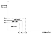
本形態は、診断領域Cを通常の診断領域Aよりも広く設定すると共に、特性診断異常検出判定レベルK3を通常の特性診断異常検出判定レベルK1よりも狭く設定して、吸入空気量センサ9の特性異常を検出するようにしたものである。 In this embodiment, the diagnosis area C is set wider than the normal diagnosis area A, the characteristic diagnosis abnormality detection determination level K3 is set narrower than the normal characteristic diagnosis abnormality detection determination level K1, and the intake air amount sensor 9 A characteristic abnormality is detected.
すなわち、図10に示すルーチンでは、先ず、ステップS21で、燃料系システムの故障診断において設定されるリッチ異常フラグの値を参照して、リッチ異常が検出されたか否かを調べる。図13(a)に示すように、リッチ異常フラグは正常時は0、異常時は1にセットされる。そして、リッチ異常フラグ=1の異常時はステップS22へ進み、又、リッチ異常フラグ=0の正常時はそのままルーチンを抜ける。 That is, in the routine shown in FIG. 10, first, in step S21, it is checked whether or not a rich abnormality is detected by referring to the value of the rich abnormality flag set in the failure diagnosis of the fuel system. As shown in FIG. 13A, the rich abnormality flag is set to 0 when normal and 1 when abnormal. When the rich abnormality flag = 1 is abnormal, the process proceeds to step S22. When the rich abnormality flag = 0 is normal, the routine is directly exited.
ステップS22へ進むと、吸入空気量センサ9の出力異常を判定する特性診断条件を設定する。 In step S22, a characteristic diagnosis condition for determining an output abnormality of the intake air amount sensor 9 is set.
特性診断条件として本形態では、通常の吸気系システムの故障診断を行う際に設定されている診断領域Aを、それよりも広い診断領域Cに設定すると共に、通常の吸気系システムの故障診断を行う際に設定されている特性診断異常検出判定レベルK1[V]をK3[V]に設定する(図13(b)参照)。 As a characteristic diagnosis condition, in this embodiment, the diagnosis area A set when performing a diagnosis of a normal intake system failure is set to a diagnosis area C wider than that, and a normal diagnosis of the intake system is performed. The characteristic diagnosis abnormality detection determination level K1 [V] set at the time of performing is set to K3 [V] (see FIG. 13B).
図11に示すように、診断領域Cは、通常の吸気系システムの故障診断を行う際の診断領域Aよりも広く、且つ第2形態で設定される診断領域Bよりも狭い値に設定される。 As shown in FIG. 11, the diagnosis area C is set to a value that is wider than the diagnosis area A when performing a failure diagnosis of a normal intake system and narrower than the diagnosis area B set in the second mode. .
又、図12に示すように、特性診断異常検出判定レベルK3は、通常の吸気系システムの故障診断を行う際の特性診断異常検出判定レベルK1よりも低く、且つ第2形態で設定される特性診断異常検出判定レベルK2よりも高い値に設定される。 Also, as shown in FIG. 12, the characteristic diagnosis abnormality detection determination level K3 is lower than the characteristic diagnosis abnormality detection determination level K1 when performing normal intake system failure diagnosis, and is set in the second form. It is set to a value higher than the diagnostic abnormality detection determination level K2.
上述したように、通常の吸気系システムの故障診断の際に設定する特性診断異常検出判定レベルK1は、基準電圧に、個体差によるばらつきとシステム制御上のばらつきとを考慮した値を加算することで設定されている。本形態では、システム制御上のばらつきを考慮しない分、診断領域Aを診断領域Cに広げると共に、特性診断異常検出判定レベルK1[V]を、それよりも狭い特性診断異常検出判定レベルK3[V]に設定したものである。その結果、より厳しい断レベルで吸入空気量センサ9の出力異常を検出することになる。 As described above, the characteristic diagnosis abnormality detection determination level K1 set at the time of normal intake system failure diagnosis is to add a value that takes into account variations due to individual differences and variations in system control to the reference voltage. Is set in In this embodiment, the diagnosis area A is expanded to the diagnosis area C by considering the variation in system control, and the characteristic diagnosis abnormality detection determination level K1 [V] is set to a narrower characteristic diagnosis abnormality detection determination level K3 [V. ] Is set. As a result, the output abnormality of the intake air amount sensor 9 is detected at a more severe disconnection level.
そして、ステップS23へ進むと、診断領域(運転領域)が診断領域Cに有るか否かを調べる。図11に示すように、診断領域Cは、回転数センサ13で検出したエンジン回転数Neとスロットル開度センサ14で検出したスロットル開度θthとに基づいて判断する。
Then, when the process proceeds to step S23, it is checked whether or not the diagnosis area (operation area) is in the diagnosis area C. As shown in FIG. 11, the diagnosis region C is determined based on the engine rotational speed Ne detected by the rotational speed sensor 13 and the throttle opening degree θth detected by the throttle
そして、エンジン回転数Neが予め設定した領域判定回転数Ne2以下で、且つスロットル開度θthが予め設定した領域判定開度θth2以下のとき(Ne≦Ne2、且つθth≦θth2)、診断領域=Cと判定し、ステップS24へ進む。一方、エンジン回転数Neが予め設定した領域判定回転数Ne2より高いとき(Ne>Ne2)、或いは(及び)スロットル開度θthが予め設定した領域判定開度θth2より高いとき(θth>θth2)、診断領域から外れているため、ルーチンを抜ける。 When the engine speed Ne is equal to or smaller than a predetermined region determination rotational speed Ne2 and the throttle opening θth is equal to or smaller than a predetermined region determination opening θth2 (Ne ≦ Ne2 and θth ≦ θth2), the diagnosis region = C And the process proceeds to step S24. On the other hand, when the engine speed Ne is higher than a preset area determination speed Ne2 (Ne> Ne2), or (and) when the throttle opening degree θth is higher than a preset area determination opening degree θth2 (θth> θth2). The routine exits because it is out of the diagnostic area.
ステップS24へ進むと、吸入空気量センサ9の出力値V1と特性診断異常検出判定レベルK3とを比較する。そして、V1<K3のときは、ステップS25へ分岐し、吸入空気量センサ9の出力特性は正常であると判定し、特性診断正常異常判定フラグをクリア(=0)して、ルーチンを抜ける。一方、V1≧K3のときは、ステップS26へ進み、吸入空気量センサ9の出力特性が異常であると判定し、特性診断正常異常判定フラグをセット(=1)して、ルーチンを抜ける。 In step S24, the output value V1 of the intake air amount sensor 9 is compared with the characteristic diagnosis abnormality detection determination level K3. When V1 <K3, the process branches to step S25, where it is determined that the output characteristic of the intake air amount sensor 9 is normal, the characteristic diagnosis normal / abnormal determination flag is cleared (= 0), and the routine is exited. On the other hand, when V1 ≧ K3, the process proceeds to step S26, where it is determined that the output characteristic of the intake air amount sensor 9 is abnormal, the characteristic diagnosis normal / abnormal determination flag is set (= 1), and the routine is exited.
ところで、図11に示す吸入空気量センサ特性診断ルーチンでは、燃料系システムの故障診断においてリッチ異常が検出された場合について説明したが、リーン異常が検出された場合にも、吸気系システムの故障診断を行う。リーン異常が検出されたときの、吸入空気量センサ9の故障診断について簡単に説明する。 In the intake air amount sensor characteristic diagnosis routine shown in FIG. 11, the case where the rich abnormality is detected in the failure diagnosis of the fuel system has been described. However, the failure diagnosis of the intake system is also performed when the lean abnormality is detected. I do. The failure diagnosis of the intake air amount sensor 9 when a lean abnormality is detected will be briefly described.
先ず、リーン異常フラグの値を参照して、正常時を示す0から異常時を示す1に切り替った後、通常の吸気系システムの故障診断を行う際に設定されている診断領域Aを、それよりも広い診断領域Cに設定すると共に、特性診断異常検出判定レベルK1をそれよりも狭い特性診断異常検出判定レベルK3に設定する。次いで、診断領域Cにおいて、吸入空気量センサ9の出力値V1と特性診断異常検出判定レベルK3とを比較し、V1>K3のときは、吸入空気量センサ9の出力特性は正常であると判定し、特性診断正常異常判定フラグをクリア(=0)する。一方、V1≦K3のときは、吸入空気量センサ9の出力特性が異常であると判定し、特性診断正常異常判定フラグをセット(=1)する。 First, referring to the value of the lean abnormality flag, after switching from 0 indicating normal time to 1 indicating abnormal time, the diagnosis region A set when performing a normal intake system failure diagnosis, A wider diagnostic area C is set, and the characteristic diagnosis abnormality detection determination level K1 is set to a narrower characteristic diagnosis abnormality detection determination level K3. Next, in the diagnosis region C, the output value V1 of the intake air amount sensor 9 is compared with the characteristic diagnosis abnormality detection determination level K3. When V1> K3, it is determined that the output characteristic of the intake air amount sensor 9 is normal. Then, the characteristic diagnosis normal / abnormal determination flag is cleared (= 0). On the other hand, when V1 ≦ K3, it is determined that the output characteristic of the intake air amount sensor 9 is abnormal, and a characteristic diagnosis normal / abnormal determination flag is set (= 1).
尚、本発明のは、上述した各形態に限るものではなく、例えば吸気系センサは吸入空気量センサ以外に、スロットル弁4下流の吸入管圧力を検出する吸入管圧力センサであっても良い。 The present invention is not limited to the above-described embodiments. For example, the intake system sensor may be an intake pipe pressure sensor that detects the intake pipe pressure downstream of the throttle valve 4 in addition to the intake air amount sensor.
1…エンジン、9…吸入空気量センサ、13…回転数センサ、14…スロットル開度センサ、20…電子制御装置、θth…スロットル開度、A,B,C…診断領域、K2,K3…特性診断異常検出判定レベル、V1…出力値
代理人 弁理士 伊 藤 進
DESCRIPTION OF
Agent Patent Attorney Susumu Ito
Claims (6)
上記吸気系センサ特性診断実行手段は、
故障診断を実行する診断領域を設定する診断領域設定手段と、
上記出力特性と比較する特性診断異常検出レベルを設定する特性診断異常検出判定レベル設定手段と、
上記診断領域と上記特性診断異常検出レベルとに基づいて上記吸気系センサの出力特性の異常の有無を判定する異常判定手段と
を備えることを特徴とする燃料系システムの故障診断装置。 Intake system sensor characteristic diagnosis execution means for diagnosing the output characteristics of the intake system sensor when an abnormality is detected in the failure diagnosis of the fuel system,
The intake system sensor characteristic diagnosis execution means includes:
Diagnostic area setting means for setting a diagnostic area for executing fault diagnosis;
A characteristic diagnosis abnormality detection determination level setting means for setting a characteristic diagnosis abnormality detection level to be compared with the output characteristic;
A failure diagnosis device for a fuel system, comprising: an abnormality determination means for determining whether there is an abnormality in the output characteristics of the intake system sensor based on the diagnosis region and the characteristic diagnosis abnormality detection level.
Priority Applications (1)
| Application Number | Priority Date | Filing Date | Title |
|---|---|---|---|
| JP2004108096A JP2005291102A (en) | 2004-03-31 | 2004-03-31 | Failure diagnosis device for fuel system |
Applications Claiming Priority (1)
| Application Number | Priority Date | Filing Date | Title |
|---|---|---|---|
| JP2004108096A JP2005291102A (en) | 2004-03-31 | 2004-03-31 | Failure diagnosis device for fuel system |
Publications (1)
| Publication Number | Publication Date |
|---|---|
| JP2005291102A true JP2005291102A (en) | 2005-10-20 |
Family
ID=35324314
Family Applications (1)
| Application Number | Title | Priority Date | Filing Date |
|---|---|---|---|
| JP2004108096A Pending JP2005291102A (en) | 2004-03-31 | 2004-03-31 | Failure diagnosis device for fuel system |
Country Status (1)
| Country | Link |
|---|---|
| JP (1) | JP2005291102A (en) |
Cited By (2)
| Publication number | Priority date | Publication date | Assignee | Title |
|---|---|---|---|---|
| WO2011092805A1 (en) * | 2010-01-27 | 2011-08-04 | トヨタ自動車株式会社 | Anomaly assessment device and anomaly assessment method of control system |
| CN110987448A (en) * | 2019-12-05 | 2020-04-10 | 潍柴动力股份有限公司 | Engine air inlet state monitoring method, device and equipment |
-
2004
- 2004-03-31 JP JP2004108096A patent/JP2005291102A/en active Pending
Cited By (4)
| Publication number | Priority date | Publication date | Assignee | Title |
|---|---|---|---|---|
| WO2011092805A1 (en) * | 2010-01-27 | 2011-08-04 | トヨタ自動車株式会社 | Anomaly assessment device and anomaly assessment method of control system |
| JP5299525B2 (en) * | 2010-01-27 | 2013-09-25 | トヨタ自動車株式会社 | Control system abnormality determination device and abnormality determination method |
| US8762791B2 (en) | 2010-01-27 | 2014-06-24 | Toyota Jidosha Kabushiki Kaisha | Error determination device and error determination method of control system |
| CN110987448A (en) * | 2019-12-05 | 2020-04-10 | 潍柴动力股份有限公司 | Engine air inlet state monitoring method, device and equipment |
Similar Documents
| Publication | Publication Date | Title |
|---|---|---|
| US7146851B2 (en) | Diagnostic apparatus for variable valve control system | |
| JP3884577B2 (en) | Control device for internal combustion engine | |
| JP4618220B2 (en) | Gas sensor assembly state detection method and gas sensor assembly state detection apparatus | |
| JP4736058B2 (en) | Air-fuel ratio control device for internal combustion engine | |
| JP4468039B2 (en) | Failure diagnosis device for exhaust gas recirculation device | |
| US6752128B2 (en) | Intake system failure detecting device and method for engines | |
| JP2009257280A (en) | Diagnostic device of exhaust gas recirculation system | |
| JP4335167B2 (en) | Internal combustion engine control device | |
| KR940004347B1 (en) | Fuel control system | |
| US10487765B2 (en) | Failure detection apparatus for fuel systems of engine | |
| JP2008223516A (en) | Failure diagnosis device of exhaust gas recirculation device for engine | |
| JP3619180B2 (en) | Abnormality diagnosis device for internal combustion engine | |
| KR102250296B1 (en) | Apparatus and method for monitering cylinder imbalance of multi-cylinder internal combustion engine | |
| JP4868173B2 (en) | Abnormality diagnosis device for internal combustion engine | |
| JP5056548B2 (en) | Intake system fault diagnosis device for in-vehicle internal combustion engine | |
| US7324891B2 (en) | Engine control method and device | |
| KR20160070647A (en) | Failure Diagnosis Method for Oxygen Sensor, and Monitoring System for Exhaust Gas Operated Thereby | |
| JP2005291102A (en) | Failure diagnosis device for fuel system | |
| US9506416B2 (en) | Inter-cylinder air-fuel ratio variation abnormality detection apparatus for multicylinder internal combustion engine | |
| JP5603825B2 (en) | Air-fuel ratio sensor diagnostic device | |
| US7280911B2 (en) | Method for the detection of faults in the engine control in internal combustion engines having at least two control units | |
| JP4830741B2 (en) | Fault diagnosis system for internal combustion engine | |
| JP4259570B2 (en) | Valve abnormality determination device, abnormality determination method, program for realizing the method, and recording medium recording the program | |
| KR102042817B1 (en) | Diagnosis Method For Fuel System Of Flexible Fuel Vehicle, And FFV Operated Thereby | |
| JP4387866B2 (en) | Response diagnosis device for oxygen sensor in engine |
Legal Events
| Date | Code | Title | Description |
|---|---|---|---|
| A621 | Written request for application examination |
Free format text: JAPANESE INTERMEDIATE CODE: A621 Effective date: 20070322 |
|
| A977 | Report on retrieval |
Free format text: JAPANESE INTERMEDIATE CODE: A971007 Effective date: 20090305 |
|
| A131 | Notification of reasons for refusal |
Free format text: JAPANESE INTERMEDIATE CODE: A131 Effective date: 20090324 |
|
| A521 | Written amendment |
Effective date: 20090522 Free format text: JAPANESE INTERMEDIATE CODE: A523 |
|
| A02 | Decision of refusal |
Effective date: 20090623 Free format text: JAPANESE INTERMEDIATE CODE: A02 |