EP2530438B1 - Outil de mesure de débit et son usage - Google Patents
Outil de mesure de débit et son usage Download PDFInfo
- Publication number
- EP2530438B1 EP2530438B1 EP12170442.3A EP12170442A EP2530438B1 EP 2530438 B1 EP2530438 B1 EP 2530438B1 EP 12170442 A EP12170442 A EP 12170442A EP 2530438 B1 EP2530438 B1 EP 2530438B1
- Authority
- EP
- European Patent Office
- Prior art keywords
- flow
- sensor
- tube
- resistor element
- flow sensor
- Prior art date
- Legal status (The legal status is an assumption and is not a legal conclusion. Google has not performed a legal analysis and makes no representation as to the accuracy of the status listed.)
- Active
Links
Images




Classifications
-
- G—PHYSICS
- G01—MEASURING; TESTING
- G01F—MEASURING VOLUME, VOLUME FLOW, MASS FLOW OR LIQUID LEVEL; METERING BY VOLUME
- G01F1/00—Measuring the volume flow or mass flow of fluid or fluent solid material wherein the fluid passes through a meter in a continuous flow
- G01F1/68—Measuring the volume flow or mass flow of fluid or fluent solid material wherein the fluid passes through a meter in a continuous flow by using thermal effects
- G01F1/684—Structural arrangements; Mounting of elements, e.g. in relation to fluid flow
- G01F1/6845—Micromachined devices
-
- G—PHYSICS
- G01—MEASURING; TESTING
- G01F—MEASURING VOLUME, VOLUME FLOW, MASS FLOW OR LIQUID LEVEL; METERING BY VOLUME
- G01F1/00—Measuring the volume flow or mass flow of fluid or fluent solid material wherein the fluid passes through a meter in a continuous flow
- G01F1/76—Devices for measuring mass flow of a fluid or a fluent solid material
- G01F1/78—Direct mass flowmeters
- G01F1/80—Direct mass flowmeters operating by measuring pressure, force, momentum, or frequency of a fluid flow to which a rotational movement has been imparted
- G01F1/84—Coriolis or gyroscopic mass flowmeters
- G01F1/8409—Coriolis or gyroscopic mass flowmeters constructional details
- G01F1/844—Coriolis or gyroscopic mass flowmeters constructional details microfluidic or miniaturised flowmeters
- G01F1/8445—Coriolis or gyroscopic mass flowmeters constructional details microfluidic or miniaturised flowmeters micromachined flowmeters
-
- G—PHYSICS
- G01—MEASURING; TESTING
- G01F—MEASURING VOLUME, VOLUME FLOW, MASS FLOW OR LIQUID LEVEL; METERING BY VOLUME
- G01F25/00—Testing or calibration of apparatus for measuring volume, volume flow or liquid level or for metering by volume
- G01F25/10—Testing or calibration of apparatus for measuring volume, volume flow or liquid level or for metering by volume of flowmeters
- G01F25/13—Testing or calibration of apparatus for measuring volume, volume flow or liquid level or for metering by volume of flowmeters using a reference counter
-
- G—PHYSICS
- G01—MEASURING; TESTING
- G01F—MEASURING VOLUME, VOLUME FLOW, MASS FLOW OR LIQUID LEVEL; METERING BY VOLUME
- G01F7/00—Volume-flow measuring devices with two or more measuring ranges; Compound meters
Definitions
- the present invention relates to a flow meter for determining a flow of a medium, said flow meter comprising a flow tube for transporting the medium whose flow is to be measured, wherein the flow tube has a first end and a second end at a distance therefrom, and wherein the flow meter is provided with a first flow sensor for measuring the flow of the medium at a first position of the flow tube.
- the present invention also relates to the use of such a flow meter.
- Such a flow meter is known, for example from EP 2078936 .
- the known flow meter is provided with a system chip and comprises a substrate provided with an opening, in which opening a silicon nitride flow tube is present for transporting medium whose flow is to be measured.
- the flow tube described in EP 2068936 forms part of a Coriolis flow sensor and is suitable for measuring very low mass flows, to values far below 1 gram per hour.
- the flow tube forms part of a so-called thermal flow sensor.
- the known flow meter and the known method are limited as regards their accuracy and/or measurable range.
- the known flow meter is quite satisfactory, there is a need for a flow meter and a method by means of which the flow, for example the mass flow, can be determined more accurately and/or within a larger measuring range.
- EP 1 411 355 A1 Another flow meter is known from EP 1 411 355 A1 , which describes a flow meter of the thermal type, which is provided with a flow sensor of the Coriolis type.
- the present invention provides a flow meter of the kind described in the introduction, which is characterised by the features defined in the characterising portion of claim 1.
- the flow meter comprises a flow tube for transporting the medium whose flow is to be measured.
- the flow meter is provided with a first flow sensor for measuring the flow of the medium at a first position of the flow tube. The first position lies in between the first end and the second end.
- the flow meter is also provided with a second flow sensor for measuring the flow of the medium at a second position of the flow tube. The second position lies in between the first end and the second end.
- the first flow sensor and the second flow sensor are designed for measuring the flow through the flow tube, preferably independently of each other.
- the second, additional flow sensor provides additional measuring data, from which additional information about the flow to be measured can be derived.
- This additional information makes it possible to measure the flow through the flow tube more accurately, and/or to increase the range of the flow meter, which will be explained in more detail hereinafter.
- an improved flow meter is obtained. The object of the present invention is thus achieved.
- the first flow sensor and the second flow sensor may be designed for measuring the flow at the same position of the flow tube. In order to further increase the independence of the measurements of the two flow sensors, it is preferable, however, if the second position is spaced from the first position.
- the first end is a supply end
- the second end is a discharge end positioned downstream from the supply end
- the flow tube comprises a further opening, positioned between the two ends, and which further opening is suitable for supplying or discharging the medium of which the flow is to be measured.
- the further opening is positioned between the first and the second position, which positions are preferably positioned at a distance from each other, as described above. With such a further opening it is possible to position the first flow sensor and the second flow sensor in parallel. In absence of a further opening, the flow sensors are positioned in series.
- the flow tube may comprise several flow tube parts, and that the flow tube does not need to be an integrally formed part.
- the flow meter may comprise a flow sensor of the Coriolis type.
- a Coriolis flow sensor is known per se to those skilled in the art.
- the first flow sensor may be of the Coriolis type.
- a flow sensor of the Coriolis type is quite suitable for measuring the mass flow of the flow on the basis of flow-induced vibrations in the flow tube.
- the flow meter comprises a thermal flow sensor.
- a flow sensor of this type is known per se to those skilled in the art.
- both the first and the second flow sensors are thermal flow sensors.
- Such a sensor is quite suitable for measuring very low mass flows, making use of very small flow-induced temperature changes.
- the accuracy of the flow meter can be increased in a very efficient manner if the flow meter comprises calibration means for calibrating the first flow sensor on the basis of at least a signal delivered by the second flow sensor.
- a signal from the second flow sensor can be used for checking the first flow sensor and adjusting it, if necessary, such that the signal delivered by the first flow sensor is representative of the flow.
- Flow sensors are designed for measuring the flow within a specific measuring range.
- the term "measuring range” as used herein is understood to mean: the range in values of a specific parameter that can be (accurately) measured by the flow sensor. Within this context also the lower boundary that can be measured by the flow sensor and the upper boundary that can be measured by the flow sensor are important. If the flow sensor is designed for measuring the volume flow, for example, said range can be expressed in nanolitres per second.
- the first flow sensor is designed for measuring the flow within a first measuring range
- the second flow sensor is designed for measuring the flow within a second measuring range.
- the response rate of the flow meter according to the present invention can be relatively high, precisely because use is made of two flow sensors.
- the flow sensors may be selected so that the first measuring range and the second measuring range overlap.
- the flow sensors are configured so that the first measuring range and the second measuring range overlap only partially. In this way the measurable range can be increased in a simple manner.
- the first flow sensor is a thermal flow sensor and the second flow sensor is a flow sensor of the Coriolis type.
- the first thermal flow sensor is provided with: a first sensor circuit, comprising a first resistor element, which is temperature-sensitive and which is thermally connected to the flow tube, and a second resistor element that can be electrically connected in series therewith; a first voltage measuring element which is electrically connectable between the first and the second resistor element; first heating means for heating the flow tube at least partially at the location of the first resistor element; and wherein the second thermal flow sensor is provided with; a second sensor circuit, comprising a third resistor element which is temperature-sensitive and which is thermally connected to the flow tube, and a fourth resistor element that can be electrically connected in series therewith; a second voltage measuring element which is electrically connectable between the third and the fourth resistor element; second heating means for heating the flow tube at least partially at the location of the third resistor element.
- the first sensor circuit is quite preferably electrically connected to the second sensor circuit in such a manner that said first sensor circuit and said second sensor circuit form a first half and a second half, respectively, of a Wheatstone bridge.
- the flow can in that case be measured with a full Wheatstone bridge, by means of which the flow can be measured in a relatively accurate manner.
- both the first half and the second half of the Wheatstone bridge can be separately used for measuring the flow.
- Each half of the Wheatstone bridge can be regarded as a separate thermal flow sensor.
- the flow meter is provided with switching means for selectively forming the first half of the Wheatstone bridge from two of the resistor elements and selectively forming the second half of the Wheatstone bridge from two of the remaining resistor elements.
- the switching means can be used for selectively forming a Wheatstone bridge with four resistor elements from the four (or possibly more) resistor elements that are present. Suitable switching makes it possible to eliminate measurement errors in the flow meter, and possibly for correcting or calibrating the first half of the Wheatstone bridge (first flow sensor) on the basis of the signal obtained by the second half of the Wheatstone bridge (second flow sensor).
- the second resistor element and/or the fourth resistor element in the Wheatstone bridge is/are temperature-sensitive.
- the temperature-sensitive resistor element may be connected to the flow tube, but it may also be used for measuring the temperature of the system chip, possibly for the purpose of thus calibrating for changes in the temperature thereof.
- the second resistor element and/or the fourth resistor element are thermally connected to the flow tube.
- the first half of the Wheatstone bridge may be designed for measuring the flow through a first part of the flow tube.
- the second half of the Wheatstone bridge may be designed for measuring the flow through a second part of the flow tube.
- Said parts (first part and second part), may be identical to each other. It is preferable, however, if said first and said second part are essentially spaced from each other.
- the first and the second resistor element are connected to the first part of the flow tube, and the third and the fourth resistor element are connected to a second part of the flow tube, which first and second parts are essentially spaced from each other.
- first part and the second part are disposed opposite each other.
- said parts extend parallel to each other. It is preferable in that regard if said parts are disposed so that the directions of flow through said parts are essentially opposite to each other. As a result, the effects of external temperature gradients on the signal from the thermal sensor are averaged out.
- the first heating means comprise at least the first and/or the second resistor element. Additionally, or separate therefrom, the second heating means may comprise at least the third and/or the fourth resistor element.
- An additional advantage of the flow meter according to the invention is that it is very suitable for carrying out measurements on different types of medium, among which different gases and/or liquids. If a thermal flow sensor is used with a Coriolis flow sensor, the thermal flow sensor may be calibrated for thus correcting for differences in, for example, the density of the medium.
- the invention relates to the use of a flow meter according to the present invention. Said use enables the user to determine the flow in a relatively accurate manner. Additionally, the use of the flow meter makes it possible to determine the flow over a larger measuring range. Further advantages of such a use of a flow meter have already been discussed in the foregoing.
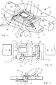
- FIG. 1a shows a flow meter 1.
- the flow meter 1 is provided with a system chip comprising a monocrystalline silicon substrate 16 provided with two openings 51, 52 that have been etched therein.
- the monolithic system chip 16 is combined into one unit with two permanent magnets 31, 32 disposed opposite each other, which are mounted on a carrier 14, for example a PCB (printed circuit board) of a ceramic or a plastic material with copper conductors thereon.
- the substrate 16 is made from an Si wafer and is mounted on the carrier 14.
- the electrical connections between the system chip and the carrier are provided by so-called bond wires in groups 81, 82, 83.
- the flow tube 21, 22 for transporting a medium whose flow is to be measured.
- the flow tube 21, 22 comprises a first end 4 in the form of a supply end 4 and a second end 6 in the form of a discharge end 6 disposed downstream thereof.
- the flow tube is provided with a first flow sensor 11 and a second flow sensor 12 for measuring the flow through the flow tube 21, 22 at a first and a second position.
- the flow meter 1 comprises a Coriolis flow sensor 11, with a silicon nitride Coriolis tube 21 in the illustrated embodiment, which is freely suspended in a first opening 51.
- a flow meter is known per se to the skilled person, for example from EP 2 078 936 , which document is incorporated in the present patent application by reference.
- a mass flow through the Coriolis tube will lead to a vibration of the Coriolis tube that is related to said mass flow.
- the vibration can be read out by means of read-out elements.
- the Coriolis tube is loop-shaped, said loop shape being a rectangular shape in this case. Other loop shapes, such as triangular, trapezoidal or U-shapes are also conceivable, of course.
- the system chip shown in figure 1 may comprise an absolute pressure sensor 18, such as a Pirani pressure sensor 18, for example in that it is integrated in or on the substrate 16.
- the pressure sensor 18 can be used for correcting the measured vibration of the Coriolis tube 21 for the air pressure.
- a thermal flow sensor 12 Provided at a second position of the flow tube is a thermal flow sensor 12, with a silicon nitride tube part 21 that is fixedly suspended in a second opening 52. The second position is spaced from the first position.
- the tube part 21 of the thermal flow sensor 12 crosses the opening entirely, and the connecting part 23 of the tube part with the discharge end is an embedded channel 23 in the substrate (see figure 1b ).
- a thermal flow sensor is known per se to the skilled person, although it can be configured in many ways. A few possible embodiments of the thermal flow sensor will be explained in more detail hereinafter.
- the thermal flow sensor comprises a Wheatstone bridge (not shown) comprising four resistor elements, at least one temperature-sensitive resistor of which is thermally connected to the flow tube.
- a heating element heats a part of the flow tube that is located in the vicinity of the temperature-sensitive resistor.
- the flow in the tube will carry along heat in downstream direction.
- the temperature at the location of the temperature-sensitive resistor will increase or decrease, depending on whether the temperature-sensitive resistor is disposed downstream or upstream, respectively, of the heating element.
- the increase or decrease in temperature leads to a change in the resistance of the temperature-sensitive resistor, which can subsequently be read out by means of the Wheatstone bridge and can be related to a measure of the flow, preferably to the mass flow of the medium.
- the thermal flow sensor comprises two tube parts disposed opposite each other, which are each provided with a temperature-sensitive resistor. Each temperature-sensitive resistor is incorporated in one half of the Wheatstone bridge. Further variations of the thermal flow sensor are conceivable, of course.
- the thermal flow sensor 301 that is shown in said figure comprises a flow tube 320, which comprises two silicon nitride tube parts 321, 322 which are fixedly suspended in the opening in the substrate 314. Via embedded channels having an inlet 304 and an outlet 306, medium can flow through the flow tubes 321, 322.
- Two heater elements 340 are placed on the first tube part, in the centre of the tube part. Heater elements 340 are also placed on the second tube part 322.
- Two thermopiles 331, 332 are symmetrically arranged between the two legs 321, 322 on either side of the heaters 340.
- a film 341, 342 is provided between the two legs, on which film the thermopiles 331, 332 are supported.
- said thermal flow sensor comprises a loop-shaped tube essentially in the form of a U, which is freely suspended.
- a heating resistor is arranged in the centre of the connecting leg of the free tube.
- a thermopile is arranged between the two legs of the free tube for measuring a temperature difference between the legs, which temperature difference is a measure of the flow.
- the U-shaped tube may be fixed to the opposite wall of the opening with the connecting leg of the U, or may extend into the substrate via an embedded channel (analogously to the embodiment shown in figure 2b ).
- a double version of the above-described thermal sensor is obtained by providing a heater resistor on both legs, for example in the centre thereof.
- Thermopiles may be symmetrically arranged between the two legs on either side of the heaters.
- Figure 1b shows a top plan view of the system chip of figure 1a .
- the system chip comprises a flow tube 20, which extends between the first connection 4 and the second connection 6.
- the flow tube 20 forms part of a Coriolis flow meter 11.
- the flow tube 20 forms part of a thermal flow sensor 12.
- the medium may first flow through the flow tube part of the thermal flow sensor 12 and subsequently through the flow tube part of the Coriolis flow sensor 11, or conversely.
- the sequence to be selected of the two flow sensors is not limited.
- Figure 1c shows the device of figure 1a , along a section at the location of the thermal flow sensor 12.
- the figure clearly shows the manner in which the hydraulic connection between the connections 6 (end parts) of the flow tube 20 and further flow tubes 61 is effected by means of a pressure block 71 and a pressure block 15.
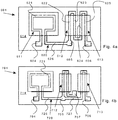
- Figure 2a shows a flow meter 101 according to another embodiment.
- the flow meter 101 is provided with a system chip comprising a monocrystalline silicon substrate 114, which is provided with an opening 152 that has been etched therein.
- the system chip may be made analogously to the system chip described above with reference to figure 1a .
- the flow tube 120 for transporting medium whose flow is to be measured.
- the flow tube 120 comprises a first end 104 in the form of a supply end 104 and at a distance therefrom, a second end 106 in the form of a discharge end 106, positioned downstream from the supply end.
- the flow tube 120 is loop-shaped with two legs 121, 122 and a connecting part 123. The two legs cross the opening 152 entirely, and there is an embedded channel 123 (illustrated in dotted lines) in the substrate, which forms the connecting part of the two legs.
- the flow tube is provided with a first thermal flow sensor 111 and a second thermal flow sensor 112 for measuring the flow through the flow tube 120 at a first and a second position.
- the first thermal flow sensor 111 is provided on the first leg 121.
- the first thermal flow sensor 111 is provided with a first resistor element 131 which is temperature-sensitive and which is thermally connected to the flow tube 121.
- a second resistor element 132 is provided at a location spaced from the first resistor element 131. In the illustrated embodiment, said second resistor element is temperature-sensitive and thermally connected to the flow tube 121, although this is not absolutely necessary.
- the resistor elements 131, 132 form part of a first sensor circuit.
- the first resistor element 131 is electrically connected in series to the second resistor element 132.
- a first voltage measuring element is connectable between the first resistor element 131 and the second resistor element 132.
- the resistor elements form heating means for heating the flow tube at least partially at the location of the first resistor element 131. With this object in mind it is also possible, however, to provide separate heating elements, as for example described above with reference to figure 3b .
- the second thermal flow sensor 112 is provided on the second leg 122. Analogously to the first thermal flow sensor, the second thermal flow sensor 112 is provided with a second sensor circuit comprising a third resistor element 133, which is temperature-sensitive and which is thermally connected to the flow tube 122, and a fourth resistor element 134, which can be electrically connected in series thereto. In the illustrated embodiment, the fourth resistor element 134 is temperature-sensitive and thermally connected to the flow tube 122, although this is not absolutely necessary.
- a second voltage measuring element is connectable between the third resistor element 133 and the fourth resistor element 134.
- the second leg 122 too, comprises heating means for heating the flow tube 122 at least partially at the location of the third resistor element 133. In this embodiment, the resistor elements form heating elements, although other embodiments are conceivable.
- Figure 2c schematically shows the two spaced-apart tube parts 121, 122 of figure 2a .
- the direction of flow through the tube parts 121, 122 is indicated by the arrows F1, F2.
- the flow takes place from the left to the right in the drawing (indicated by the arrow F1)
- the second tube part 122 the flow takes place in the opposite direction, viz. from the right to the left in the drawing (indicated by the arrow F2).
- the first tube part 121 comprises two spaced-apart resistors 131, 132, which are temperature-sensitive.
- the two resistors form part of a first half of a Wheatstone bridge, as described above with reference to figure 2a .
- the resistors 131, 132 are also configured as heating elements for heating the tube part 121.
- the second tube part 122 is configured analogously to the first tube part 121, comprising two temperature-sensitive resistors 133, 134 which are thermally connected to the second tube part 122. Said resistors, too, function as heating elements for heating the second tube part.
- a dotted line M0, M0' illustrates the temperature profile of the two tube parts in the situation where there is no flow through the tube part.
- the temperature in the tube parts 121, 122 will change. This is schematically illustrated in the full line M1, M1'.
- the temperature in the part upstream of the centre of the tube part will decrease as a result of the flow and increase in the part downstream thereof.
- the decrease and the increase are a measure of the flow.
- the second tube part 122 As a result of the flow, the temperature will successively decrease an increase in the second tube part as well.
- the temperature changes over time can be determined relatively accurately by means of the temperature-sensitive resistors on 131, 132, 133, 134, so that the flow through the tube parts 121, 122 is also measurable.
- any temperature gradients in the direction of flow F1, F2 are averaged out in that the effect of the temperature gradient on the measuring results for the first tube part is the exact opposite of the effect of the temperature gradient on the measuring results of the second tube part.
- the first resistor element 131 and the second resistor element 132 may be electrically connected in such a manner as to form a half Wheatstone bridge.
- the measure of the flow can then be determined on the basis of the resistance change in the first resistor element 131 and/or the second resistor element 132.
- the third resistor element 133 and the fourth resistor element 134 may be configured in the same way, connected as a half Wheatstone bridge, with reference resistors 150, 151 as the complementary half of the Wheatstone bridge.
- the first thermal flow sensor 111 and the second thermal flow sensor 112 are electrically connected, as schematically shown in figure 2e , and that in such a manner that the first sensor circuit and the second sensor circuit form a first half and a second half, respectively, of a Wheatstone bridge.
- the flow can in that case be measured with a full Wheatstone bridge, by means of which the flow can be measured in a relatively accurate manner.
- both the first half and the second half of the Wheatstone bridge can be used separately for measuring the flow.
- Each half of the Wheatstone bridge can thus be regarded as a separate thermal flow sensor.
- the resistors in the Wheatstone bridge can be selectively connected.
- the flow meter may to that end be provided with switching means for selectively forming the first half of the Wheatstone bridge from two of the resistor elements and selectively forming the second half of the Wheatstone bridge from two of the remaining resistor elements.
- switching means for selectively forming the first half of the Wheatstone bridge from two of the resistor elements and selectively forming the second half of the Wheatstone bridge from two of the remaining resistor elements.
- the first half of the Wheatstone bridge comprises a cold resistor R1 and a hot resistor R2, and the second half of the Wheatstone bridge also comprises a cold resistor R4 and a hot resistor R3.
- R1 corresponds to the resistor element 131
- R2 corresponds to the resistor element 132
- R3 corresponds to the resistor element 134
- R4 corresponds to the resistor element 133.
- the hot resistors R2, R3 are disposed diagonally opposite each other in the Wheatstone bridge, as it were, as are the cold resistors R1, R4. Permutations of the various resistors are conceivable, of course. Said switching in this configuration A can be used for correcting for a fixed error.
- the first half of the Wheatstone bridge comprises a cold resistor R1 and a hot resistor R2, and the second half of the Wheatstone bridge also comprises a cold resistor R4 and a hot resistor R3.
- the hot resistors are disposed beside each other, as it were, as are the cold resistors. Permutations of the various resistors are conceivable, of course.
- a measuring circuit is obtained from two parts of the Wheatstone bridge that normally oppose one another.
- the first half of the Wheatstone bridge comprises all the hot resistors R3, R2, whilst the second half of the Wheatstone bridge comprises all the cold resistors R1, R4.
- the measured value of the Wheatstone bridge should equal zero in this situation. In case of a deviation, correction for this is possible. Permutations of the various resistors are conceivable, of course.
- the flow meter 101 of figure 2a can also be used as a thermal flow sensor in combination with the Coriolis flow sensor 11 shown in figure 1a .
- Figure 2b is a view of the flow meter 171 of figure 1a , in which the thermal flow sensor 12 of figures 1a-c has been exchanged for the flow meter 101 of figure 2a .
- a flow meter 171 comprising a flow tube with three flow sensors for measuring the flow of the medium at three (different) positions is obtained here.
- FIG. 3a shows an embodiment of a flow meter 201 with a total of four thermal flow sensors.
- the flow meter comprises a flow tube 220 with an inlet 204 and an outlet 206, and with a total of four tube parts 221, 222, 223, 224, which are each freely suspended in an opening in a substrate 214. Via embedded channels 225, 226, 227 a loop-shaped float tube is obtained.
- Each tube part comprises a half Wheatstone bridge, each half comprising two resistor elements (231, 232; 233, 234; 235, 236; 237, 238) which are temperature-sensitive and which also serve as heating elements.
- the four half Wheatstone bridges can be selectively combined to form a full Wheatstone bridge.
- Figure 3c shows an embodiment of a flow meter 401 comprising a number of thermal flow sensors placed on a flow tube 420.
- the flow tube again has a first end 404, and a second end 406, in this embodiment respectively a supply end 404 and a discharge end 406.
- a few (four in total) tube parts 421, 422, 423, 424 are provided, which extend freely between an opening in the substrate 414.
- the various tube parts 421, 422, 423, 424 are connected via embedded channels 425, 426, 427 for forming a loop-shaped flow tube 420.
- Heater elements are provided in the centre of each tube part.
- Adjacent tube parts are connected by means of respective thermopiles 431, 432, 433, 434, 435, 436, analogously to the thermal flow sensor described with reference to figure 3b .
- the embodiment of figure 3c has the advantage that corrections for temperature gradients in the plane of the substrate 414 are possible.
- Figure 3d shows an embodiment of a flow meter 501 with a flow tube comprising four tube parts 521, 522, 523, 524, which are provided with two thermal flow sensors 533, 553.
- the tube parts are connected via embedded channels 525, 526, 527.
- the tube parts are each provided with heater elements 540 in the centre of each tube part.
- a thermopile 533, 553 is placed on either side of each of said heater elements. Each thermopile extends perpendicularly to the direction of flow, over a total of four tube parts. Connections 531, 532, 551, 552 for reading the thermopiles 533, 553 are provided. Also in this embodiment, corrections for temperature gradients in the plane of the substrate 514 are possible.
- FIGS 4a-4d show alternatives of a flow meter according to the present invention.
- the inlet and outlet are consistently named as such. Those skilled in the art will appreciate, however, that the outlet can also be used as an inlet, and conversely. It will later become apparent that the outlet and the inlet may both at the same time function as outlets, or inlets, by making use of a further opening.
- Figure 4a shows an embodiment of a flow meter 601 with a flow tube 620 comprising an inlet 604 and an outlet 606.
- the flow tube 620 comprises a Coriolis flow sensor 611 and a thermal flow sensor 612, for example in the form of a thermal flow sensor as shown in figure 3a , figure 3c or figure 3d .
- An embodiment comprising two series-connected thermal flow sensors 612, 613, for example as shown in figure 3 is also conceivable, however.
- a further inlet or outlet 605 Provided between the Coriolis flow sensor 611 and the thermal flow sensor 612, 613 is a further inlet or outlet 605, which can be selectively used for bypassing the Coriolis flow sensor 611 or the thermal flow sensor(s) 612, 613.
- the further inlet or outlet 605 may, in one embodiment, be used as the sole supply opening.
- the inlet 605 is then a supply end, such that the Coriolis flow sensor 611 is positioned in parallel to the thermal flow sensors 612, 613.
- the supply end 704 then functions as a discharge opening, en the same hold for discharge end 706. Additionally, it is conceivable that, in line with the embodiment shown in Fig. 1b , only one Coriolis flow sensor 11 is positioned in parallel to only one thermal flow sensor 12.
- FIG 4b shows a flow meter 701 with a flow tube 720 comprising an inlet 704 and an outlet 706.
- the flow tube 720 comprises a Coriolis flow sensor 711 and two parallel-connected thermal flow sensors 712, 713, for example as shown in figure 2a .
- Each thermal flow sensor can thus effectively consist of more than one thermal flow sensor.
- a T-junction 705, which is embedded in the substrate 714, is provided for realising said parallel connection.
- Figure 4c shows a flow meter 801 with a flow tube 820 comprising an inlet 804 and an outlet 806.
- the flow tube 820 comprises a Coriolis flow sensor 811 and a thermal flow sensor 812, for example as shown in figure 2a .
- Said flow meter is provided with one or more shunt tubes 826, 827 connected in parallel to the thermal flow sensor, which shunt tubes are embedded in the substrate 814.
- the addition of the shunt tubes 826, 827 makes it possible to allow a greater flow through the Coriolis flow sensor 811 in comparison with the thermal flow sensor 812 and thus gear the flow to the range of the individual flow sensors.
- Figure 4d shows a flow meter 901 with a Coriolis flow sensor 911 and a thermal flow sensor 912, for example as shown in figure 2a , in which the shunt tubes 926, 927 are positioned slightly differently, and that in such a manner that precisely the Coriolis flow sensor 911 receives a lower flow than the thermal flow sensor 912.
- Figures 5a-5d show a graphic representation of the measuring range of a flow meter with a flow tube comprising at least one Coriolis flow sensor and at least one thermal flow sensor.
- the measuring range of the Coriolis flow sensor is illustrated in a dark dotted line and the measuring range of the thermal flow sensor is illustrated in a full line.
- the actual mass flow of the medium through the flow tube is shown on the horizontal axis.
- the output signal from the sensor is shown on the vertical axis.
- the output signal from the two flow sensors is important.
- the first output signal is represented on the Y1 axis; the second is represented on the Y2 axis.
- the signals in question are thus two signals which each represent a specific range of the mass flow X shown on the horizontal axis.
- the Coriolis sensor is by nature a mass flow sensor.
- the signal is to a large degree only dependent on the actual mass flow, therefore.
- the thermal flow sensor is more sensitive, to be true, but in addition to that it is also sensitive to the density and the heat capacity of the flowing medium.
- FIG. 5a shows how the Coriolis sensor 95 can be used as a calibration means for the thermal flow sensor.
- the Coriolis sensor 95 has a specific sensitivity, with a mass flow range from b to e. This can be used for calibrating the thermal flow sensor. This can be done by scaling the output signal at an unchanged mass flow. The inclination of the thermal flow sensor can thus be calibrated such that its sensitivity at a specific mass flow of the medium corresponds to the sensitivity of the Coriolis sensor.
- the signal 93 has the same sensitivity as the Coriolis sensor in that case.
- the signals 91, 93 are too sensitive; the signal 94 is too insensitive.
- Figure 5b shows how the signal from the thermal flow sensor can be adjusted by amplification for the purpose of adjusting the sensitivity of the thermal flow sensor.
- the sensitivity of the two sensors is equalised by selecting the correct amplification of the thermal flow sensor. In this way a flow meter having a relatively large dynamic range (a to e) can be obtained.
- the ranges of the two sensors partially overlap.
- Figure 5c shows how shunts as described with reference to figure 4c can be used.
- Figure 5c shows the output signal from a combination of a Coriolis sensor 95 and a thermal flow sensor 91, 92, 93, 94.
- the signal 91 shows a thermal flow sensor without a shunt. Shunts make it possible to increase the measuring range at the expense of the sensitivity of the thermal flow sensor.
- the lower range of the thermal flow sensor scales along the mass flow axis X, but not along the output signal axis Y2.
- Figure 5d shows how shunts as described above with reference to figure 4d can be used.
- Figure 5d shows the output signal from a combination of a Coriolis sensor 91, 93, 94, 95 (with or without shunts) and a thermal flow sensor 92.
- the signal 91 shows the Coriolis sensor without a shunt.
- the measurable range will increase, but the sensitivity will decrease.
- the lower limit of the measuring range will also increase if more shunts are used, however.
- Figure 6 shows a schematic top view of an embodiment of the system chip comprising a monocrystalline silicon substrate 14 provided with two openings 1051, 1052 that have been etched therein.
- the monolithic system chip 16 is combined into one unit with two permanent magnets 1031, 1032 disposed opposite each other, which are mounted on a carrier (not shown), as already described with reference to Figure 1 .
- a flow tube 1021, 1022, 1023 for transporting a medium whose flow is to be measured.
- This flow tube 1021, 1022, 1023 comprises a first end 1004 in the form of a supply end 1004 and a second end 1006 in the form of a discharge end 1006 disposed downstream of the supply end.
- the flow tube is provided with a first flow sensor 1011 and a second flow sensor 1012, both in the form of a Coriolis flow sensor.
- the flow through the flow tube 1021, 1022 may be measured at a first and a second position.
- the first Coriolis flow sensor 1011 is positioned opposite to the second Coriolis flow sensor 1012, such that between the first Coriolis flow sensor 1011 and the second Coriolis flow sensor, a mirror line is formed.
- the flow sensors are positioned in parallel. It is thinkable, however, that at the position of the tube 1013 connecting the first Coriolis sensor 1011 to the second Coriolis sensor 1012, a further connection point is present, which forms an opening for supplying or discharging the medium. Preferably, this point is used as a supply opening.
- the medium will leave the system chip via the supply end 1004 (which then is used as a discharge opening), en via the discharge end 1006. This enables a parallel arrangement of the two Coriolis flow sensors.
- the Coriolis sensors may have the same dimensions, but they can also differ from each other, and be suitable for measurement in different flow ranges. With this, it is possible to measure in a first flow range with the first Coriolis sensor, and to measure in a second flow range with the second Coriolis sensor, wherein the second flow range at least partially differs from the first flow range.
- the system chip again comprises an absolute pressure sensor 1018, such as a Pirani pressure sensor 1018, to be used for correcting the measured vibration of the Coriolis tube 21 for the air pressure.
- an absolute pressure sensor 1018 such as a Pirani pressure sensor 1018
Landscapes
- Physics & Mathematics (AREA)
- Fluid Mechanics (AREA)
- General Physics & Mathematics (AREA)
- Chemical & Material Sciences (AREA)
- Dispersion Chemistry (AREA)
- Measuring Volume Flow (AREA)
Claims (9)
- Débitmètre (1) pour déterminer un débit d'un milieu, ledit débitmètre comprenant un tube d'écoulement (21, 22) pour transporter le milieu dont le débit doit être mesuré, où le tube d'écoulement a une première extrémité et une deuxième extrémité disposée à une certaine distance de la première extrémité, et où le débitmètre est muni d'un premier capteur de débit (11) pour mesurer le débit du milieu à une première position du tube d'écoulement, et où le débitmètre est muni d'un deuxième capteur de débit (12) pour mesurer le débit du milieu à une deuxième position du tube d'écoulement,
dans lequel le premier capteur de débit est un capteur de débit du type Coriolis ou est un capteur de débit thermique, et dans lequel le deuxième capteur de débit est un capteur de débit thermique, caractérisé en ce que le débitmètre comprend une puce de système (16) qui est munie du tube d'écoulement (21, 22) et lesdits premier et deuxième capteurs de débit (11, 12) sont situés sur ladite puce de système (16). - Débitmètre selon la revendication 1, dans lequel le débitmètre (1) comprend un moyen d'étalonnage (95) pour étalonner le premier capteur de débit sur la base d'au moins un signal délivré par le deuxième capteur de débit.
- Débitmètre selon l'une quelconque des revendications précédentes 1 et 2, dans lequel le premier capteur de débit (11) est conçu pour mesurer le débit dans une première plage de mesure, et le deuxième capteur de débit (12) est conçu pour mesurer le débit dans une deuxième plage de mesure, de préférence dans lequel la première plage de mesure et la deuxième plage de mesure se chevauchent, et plus préférablement dans lequel la première plage de mesure et la deuxième plage de mesure ne se chevauchent que partiellement.
- Débitmètre (1) selon une ou plusieurs des revendications précédentes 1 à 3, dans lequel le premier capteur de débit (111) est un capteur de débit thermique et dans lequel le premier capteur thermique (111) est muni :• d'un premier circuit de capteur, comprenant un premier élément de résistance (131), qui est sensible à la température et qui est relié thermiquement au tube d'écoulement (121), et un deuxième élément de résistance (132) qui peut être relié électriquement en série à celui-ci ;• d'un premier élément de mesure de tension qui peut être relié électriquement entre les premier et deuxième éléments de résistance ;• de premiers moyens de chauffage (131, 132) pour chauffer le tube d'écoulement au moins partiellement à l'emplacement du premier élément de résistance ;et dans lequel le deuxième capteur de débit thermique est muni :• d'un deuxième circuit de capteur, comprenant un troisième élément de résistance (133) qui est sensible à la température et qui est relié thermiquement au tube d'écoulement, et un quatrième élément de résistance (134) qui peut être relié électriquement en série à celui-ci ;• d'un deuxième élément de mesure de tension qui peut être relié électriquement entre les troisième et quatrième éléments de résistance ;• de deuxièmes moyens de chauffage (133, 134) pour chauffer le tube d'écoulement au moins partiellement à l'emplacement du troisième élément de résistance ;dans lequel le premier circuit de capteur est relié électriquement au deuxième circuit de capteur de manière à ce que ledit premier circuit de capteur et ledit deuxième circuit de capteur forment une première moitié et une deuxième moitié, respectivement, d'un pont de Wheatstone.
- Débitmètre (1) selon la revendication 4, dans lequel le débitmètre est muni d'un moyen de commutation pour former sélectivement la première moitié du pont de Wheatstone à partir de deux des éléments de résistance (131, 132, 133, 134) et pour former sélectivement la deuxième moitié du pont de Wheatstone à partir de deux des éléments de résistance restants (131, 132, 133, 134).
- Débitmètre selon la revendication 4 ou 5, dans lequel le deuxième élément de résistance (132) et/ou le quatrième élément de résistance (134) est/sont sensible(s) à la température et/ou dans lequel le deuxième élément de résistance (132) et/ou le quatrième élément de résistance (134) est/sont relié(s) thermiquement au tube d'écoulement.
- Débitmètre selon l'une quelconque des revendications 4 à 6, dans lequel les premier (131) et deuxième (132) éléments de résistance sont reliés à une première partie du tube d'écoulement, et les troisième (133) et quatrième (134) éléments de résistance sont reliés à une deuxième partie du tube d'écoulement, lesquelles première et deuxième parties sont essentiellement espacées l'une de l'autre, et dans lequel, de préférence ladite première partie et ladite deuxième partie sont disposées opposées l'une à l'autre et s'étendant par exemple parallèlement l'une à l'autre.
- Débitmètre selon l'une quelconque des revendications précédentes 4 à 7, dans lequel les premiers moyens de chauffage comprennent au moins le premier (131) et/ou le deuxième élément de résistance (132), et/ou dans lequel les deuxièmes moyens de chauffage comprennent au moins le troisième (133) et/ou le quatrième élément de résistance (134).
- Utilisation d'un débitmètre selon une ou plusieurs des revendications précédentes 1 à 8.
Applications Claiming Priority (1)
| Application Number | Priority Date | Filing Date | Title |
|---|---|---|---|
| NL2006895A NL2006895C2 (nl) | 2011-06-03 | 2011-06-03 | Stromingsmeetapparaat en gebruik daarvan voor het bepalen van een stroming van een medium, alsmede werkwijze daarvoor. |
Publications (2)
| Publication Number | Publication Date |
|---|---|
| EP2530438A1 EP2530438A1 (fr) | 2012-12-05 |
| EP2530438B1 true EP2530438B1 (fr) | 2019-08-07 |
Family
ID=46148770
Family Applications (1)
| Application Number | Title | Priority Date | Filing Date |
|---|---|---|---|
| EP12170442.3A Active EP2530438B1 (fr) | 2011-06-03 | 2012-06-01 | Outil de mesure de débit et son usage |
Country Status (6)
| Country | Link |
|---|---|
| US (1) | US8881601B2 (fr) |
| EP (1) | EP2530438B1 (fr) |
| JP (1) | JP5969271B2 (fr) |
| DK (1) | DK2530438T3 (fr) |
| ES (1) | ES2743713T3 (fr) |
| NL (1) | NL2006895C2 (fr) |
Families Citing this family (11)
| Publication number | Priority date | Publication date | Assignee | Title |
|---|---|---|---|---|
| FR2977886B1 (fr) * | 2011-07-13 | 2017-03-03 | Centre Nat Rech Scient | Capteur miniaturise a element chauffant et procede de fabrication associe. |
| DE102012102094A1 (de) * | 2012-03-13 | 2013-09-19 | Pierburg Gmbh | Vorrichtung zur Bestimmung eines Gasmassenstroms sowie Verfahren zur Rekalibrierung einer derartigen Vorrichtung |
| ITBO20130024A1 (it) * | 2013-01-21 | 2014-07-22 | Medica S P A | Flussimetro differenziale per la misura del calo ponderale in trattamenti di emodialisi |
| NL2012126C2 (en) * | 2014-01-23 | 2015-07-29 | Berkin Bv | Flow measurement system and method for determining at least one property of a medium. |
| NL2014801B1 (en) * | 2015-05-13 | 2017-01-27 | Berkin Bv | Fluid flow device, comprising a valve unit, as well as method of manufacturing the same. |
| JP6475081B2 (ja) * | 2015-05-18 | 2019-02-27 | アズビル株式会社 | 熱式流量計及びその傾斜誤差改善方法 |
| DE102019107601A1 (de) * | 2019-03-25 | 2020-10-01 | Endress + Hauser Flowtec Ag | Coriolis-Messaufnehmer und Coriolis-Messgerät |
| US11262226B2 (en) * | 2020-02-17 | 2022-03-01 | GWU Design | Hybrid mass flow sensor including a thermal and coriolis principle measurement arrangements |
| US20220074775A1 (en) * | 2020-09-08 | 2022-03-10 | Guanghua Wu | Dual Tube Hybrid Coriolis Mass Flow Sensor |
| JP7500480B2 (ja) * | 2021-03-15 | 2024-06-17 | 株式会社東芝 | センサ |
| US12455180B2 (en) | 2022-12-02 | 2025-10-28 | Honeywell International Inc. | System and method for switched measuring of flow tubes of a flow meter |
Family Cites Families (25)
| Publication number | Priority date | Publication date | Assignee | Title |
|---|---|---|---|---|
| DE3632800A1 (de) * | 1986-09-26 | 1988-04-07 | Flowtec Ag | Nach dem coriolisprinzip arbeitendes massendurchflussmessgeraet |
| JPS63235800A (ja) * | 1987-03-24 | 1988-09-30 | Nec Kyushu Ltd | マスフロ−コントロ−ラ− |
| JPH07109376B2 (ja) * | 1990-03-15 | 1995-11-22 | 東京瓦斯株式会社 | 複合センサ出力信号処理方法 |
| JP3053486B2 (ja) * | 1992-02-20 | 2000-06-19 | 東京瓦斯株式会社 | フルィディックガスメータ |
| JPH08159838A (ja) * | 1994-12-09 | 1996-06-21 | Ricoh Co Ltd | 流量計 |
| JP3282773B2 (ja) * | 1994-12-12 | 2002-05-20 | 東京瓦斯株式会社 | 熱式流量計 |
| NL1001674C2 (nl) | 1995-11-17 | 1997-05-21 | Berkin Bv | Debietmeter. |
| NL1008665C1 (nl) * | 1998-03-20 | 1999-09-21 | Berkin Bv | Mediumstroommeter. |
| JP4474771B2 (ja) * | 2000-12-20 | 2010-06-09 | 株式会社デンソー | 流量測定装置 |
| US6843110B2 (en) * | 2002-06-25 | 2005-01-18 | Fluid Components International Llc | Method and apparatus for validating the accuracy of a flowmeter |
| US6796172B2 (en) * | 2002-07-31 | 2004-09-28 | Hewlett-Packard Development Company, L.P. | Flow sensor |
| EP1411355A1 (fr) * | 2002-10-18 | 2004-04-21 | Emerson Electric Co. | Procédé et dispositif permettant de déterminer une caractéristique représentative de la nature d'un gaz |
| US7040181B2 (en) * | 2004-03-19 | 2006-05-09 | Endress + Hauser Flowtec Ag | Coriolis mass measuring device |
| JP3783962B2 (ja) * | 2004-03-24 | 2006-06-07 | 株式会社オーバル | 三次モード振動式コリオリ流量計 |
| MX2007003051A (es) * | 2004-09-17 | 2007-05-21 | Emerson Electric Co | Metodo de compensacion y aparato para un flujometro de coriolis. |
| NL1028939C2 (nl) * | 2005-05-02 | 2006-11-03 | Berkin Bv | Massa flowmeter van het Coriolistype. |
| DE102005046319A1 (de) * | 2005-09-27 | 2007-03-29 | Endress + Hauser Flowtec Ag | Verfahren zum Messen eines in einer Rohrleitung strömenden Mediums sowie Meßsystem dafür |
| EP2966421B1 (fr) * | 2006-07-28 | 2021-04-28 | Micro Motion, Inc. | Débitmètre avec trois capteurs de détection |
| JP4952164B2 (ja) * | 2006-09-20 | 2012-06-13 | 株式会社デンソー | 流量計測素子、質量流量計 |
| US9211340B2 (en) | 2006-09-27 | 2015-12-15 | Paolo Botti | Means and methods of enhancing delivery to biological systems |
| JP2009115504A (ja) * | 2007-11-02 | 2009-05-28 | Yokogawa Electric Corp | 熱式流量計 |
| NL1034905C2 (nl) * | 2008-01-11 | 2009-07-14 | Berkin Bv | Stromingsmeetapparaat. |
| US7826986B2 (en) * | 2008-09-26 | 2010-11-02 | Advanced Energy Industries, Inc. | Method and system for operating a mass flow controller |
| DE102009046839A1 (de) * | 2009-11-18 | 2011-05-19 | Endress + Hauser Flowtec Ag | Meßsystem mit einer zwei parallel durchströmte Meßrohre aufweisenden Rohranordnung sowie Verfahren zu deren Überwachung |
| EP2609402B1 (fr) * | 2010-08-24 | 2021-02-17 | Schneider Electric Systems USA, Inc. | Mesure de débit multiphase |
-
2011
- 2011-06-03 NL NL2006895A patent/NL2006895C2/nl not_active IP Right Cessation
-
2012
- 2012-06-01 ES ES12170442T patent/ES2743713T3/es active Active
- 2012-06-01 EP EP12170442.3A patent/EP2530438B1/fr active Active
- 2012-06-01 DK DK12170442.3T patent/DK2530438T3/da active
- 2012-06-04 JP JP2012126662A patent/JP5969271B2/ja active Active
- 2012-06-04 US US13/487,465 patent/US8881601B2/en active Active
Non-Patent Citations (1)
| Title |
|---|
| None * |
Also Published As
| Publication number | Publication date |
|---|---|
| JP2013033026A (ja) | 2013-02-14 |
| DK2530438T3 (da) | 2019-08-26 |
| NL2006895C2 (nl) | 2012-12-04 |
| US8881601B2 (en) | 2014-11-11 |
| JP5969271B2 (ja) | 2016-08-17 |
| EP2530438A1 (fr) | 2012-12-05 |
| ES2743713T3 (es) | 2020-02-20 |
| US20120304731A1 (en) | 2012-12-06 |
Similar Documents
| Publication | Publication Date | Title |
|---|---|---|
| US8881601B2 (en) | Flow meter and use thereof for determining a flow of a medium, as well as a method therefor | |
| EP1992917B1 (fr) | Débitmètre thermique | |
| KR100485944B1 (ko) | 열식 유체센서, 유체판별장치 및 그 방법, 플로센서, 및유량계측장치 및 그 방법 | |
| US4787251A (en) | Directional low differential pressure transducer | |
| EP1477781B1 (fr) | Débitmètre massique | |
| EP1139073A1 (fr) | Débitmètre massique | |
| US5852239A (en) | Flow sensor having an intermediate heater between two temperature-sensing heating portions | |
| CN113125028B (zh) | 气流测量电路以及气流传感器 | |
| US6668642B2 (en) | Apparatus and method for thermal isolation of thermal mass flow sensor | |
| US7287424B2 (en) | Thermal type flow measurement apparatus having asymmetrical passage for flow rate measurement | |
| US6508117B1 (en) | Thermally balanced mass air flow sensor | |
| US20260002806A1 (en) | Thermal flow sensor for determining a flow rate of a fluid | |
| US6279394B1 (en) | Mass air flow meter | |
| US11788874B1 (en) | Self-powered, matched wheatstone bridge flow sensor | |
| JPS5868618A (ja) | 流量計 | |
| JPH0727582A (ja) | 質量流量センサ | |
| JPH11190647A (ja) | 熱式フローセンサを利用した流量計及びそれを利用したガスメータ | |
| JP2929356B2 (ja) | 流量計 | |
| RU215318U1 (ru) | Тепловой датчик расхода газов калориметрического типа | |
| JP2016217812A (ja) | 熱式マスフローコントローラ及びその傾斜誤差改善方法 | |
| US20050006235A1 (en) | Sensor element | |
| JPH08159838A (ja) | 流量計 | |
| JP4793098B2 (ja) | 磁気式酸素測定方法及び磁気式酸素計 | |
| JP2003090751A (ja) | フローセンサ式流量計及びその校正方法 | |
| TW384391B (en) | Thermal pulsed micro flow sensor |
Legal Events
| Date | Code | Title | Description |
|---|---|---|---|
| PUAI | Public reference made under article 153(3) epc to a published international application that has entered the european phase |
Free format text: ORIGINAL CODE: 0009012 |
|
| AK | Designated contracting states |
Kind code of ref document: A1 Designated state(s): AL AT BE BG CH CY CZ DE DK EE ES FI FR GB GR HR HU IE IS IT LI LT LU LV MC MK MT NL NO PL PT RO RS SE SI SK SM TR |
|
| AX | Request for extension of the european patent |
Extension state: BA ME |
|
| 17P | Request for examination filed |
Effective date: 20130605 |
|
| RBV | Designated contracting states (corrected) |
Designated state(s): AL AT BE BG CH CY CZ DE DK EE ES FI FR GB GR HR HU IE IS IT LI LT LU LV MC MK MT NL NO PL PT RO RS SE SI SK SM TR |
|
| STAA | Information on the status of an ep patent application or granted ep patent |
Free format text: STATUS: EXAMINATION IS IN PROGRESS |
|
| 17Q | First examination report despatched |
Effective date: 20180328 |
|
| GRAP | Despatch of communication of intention to grant a patent |
Free format text: ORIGINAL CODE: EPIDOSNIGR1 |
|
| STAA | Information on the status of an ep patent application or granted ep patent |
Free format text: STATUS: GRANT OF PATENT IS INTENDED |
|
| INTG | Intention to grant announced |
Effective date: 20190108 |
|
| GRAJ | Information related to disapproval of communication of intention to grant by the applicant or resumption of examination proceedings by the epo deleted |
Free format text: ORIGINAL CODE: EPIDOSDIGR1 |
|
| STAA | Information on the status of an ep patent application or granted ep patent |
Free format text: STATUS: EXAMINATION IS IN PROGRESS |
|
| INTC | Intention to grant announced (deleted) | ||
| GRAP | Despatch of communication of intention to grant a patent |
Free format text: ORIGINAL CODE: EPIDOSNIGR1 |
|
| STAA | Information on the status of an ep patent application or granted ep patent |
Free format text: STATUS: GRANT OF PATENT IS INTENDED |
|
| INTG | Intention to grant announced |
Effective date: 20190322 |
|
| GRAS | Grant fee paid |
Free format text: ORIGINAL CODE: EPIDOSNIGR3 |
|
| GRAA | (expected) grant |
Free format text: ORIGINAL CODE: 0009210 |
|
| STAA | Information on the status of an ep patent application or granted ep patent |
Free format text: STATUS: THE PATENT HAS BEEN GRANTED |
|
| AK | Designated contracting states |
Kind code of ref document: B1 Designated state(s): AL AT BE BG CH CY CZ DE DK EE ES FI FR GB GR HR HU IE IS IT LI LT LU LV MC MK MT NL NO PL PT RO RS SE SI SK SM TR |
|
| REG | Reference to a national code |
Ref country code: GB Ref legal event code: FG4D |
|
| REG | Reference to a national code |
Ref country code: CH Ref legal event code: EP Ref country code: AT Ref legal event code: REF Ref document number: 1164578 Country of ref document: AT Kind code of ref document: T Effective date: 20190815 |
|
| REG | Reference to a national code |
Ref country code: DK Ref legal event code: T3 Effective date: 20190823 |
|
| REG | Reference to a national code |
Ref country code: DE Ref legal event code: R096 Ref document number: 602012062613 Country of ref document: DE |
|
| REG | Reference to a national code |
Ref country code: CH Ref legal event code: NV Representative=s name: CABINET GERMAIN AND MAUREAU, CH |
|
| REG | Reference to a national code |
Ref country code: SE Ref legal event code: TRGR |
|
| REG | Reference to a national code |
Ref country code: IE Ref legal event code: FG4D |
|
| REG | Reference to a national code |
Ref country code: NL Ref legal event code: FP |
|
| REG | Reference to a national code |
Ref country code: LT Ref legal event code: MG4D |
|
| PG25 | Lapsed in a contracting state [announced via postgrant information from national office to epo] |
Ref country code: LT Free format text: LAPSE BECAUSE OF FAILURE TO SUBMIT A TRANSLATION OF THE DESCRIPTION OR TO PAY THE FEE WITHIN THE PRESCRIBED TIME-LIMIT Effective date: 20190807 Ref country code: BG Free format text: LAPSE BECAUSE OF FAILURE TO SUBMIT A TRANSLATION OF THE DESCRIPTION OR TO PAY THE FEE WITHIN THE PRESCRIBED TIME-LIMIT Effective date: 20191107 Ref country code: PT Free format text: LAPSE BECAUSE OF FAILURE TO SUBMIT A TRANSLATION OF THE DESCRIPTION OR TO PAY THE FEE WITHIN THE PRESCRIBED TIME-LIMIT Effective date: 20191209 Ref country code: NO Free format text: LAPSE BECAUSE OF FAILURE TO SUBMIT A TRANSLATION OF THE DESCRIPTION OR TO PAY THE FEE WITHIN THE PRESCRIBED TIME-LIMIT Effective date: 20191107 Ref country code: HR Free format text: LAPSE BECAUSE OF FAILURE TO SUBMIT A TRANSLATION OF THE DESCRIPTION OR TO PAY THE FEE WITHIN THE PRESCRIBED TIME-LIMIT Effective date: 20190807 |
|
| PG25 | Lapsed in a contracting state [announced via postgrant information from national office to epo] |
Ref country code: RS Free format text: LAPSE BECAUSE OF FAILURE TO SUBMIT A TRANSLATION OF THE DESCRIPTION OR TO PAY THE FEE WITHIN THE PRESCRIBED TIME-LIMIT Effective date: 20190807 Ref country code: IS Free format text: LAPSE BECAUSE OF FAILURE TO SUBMIT A TRANSLATION OF THE DESCRIPTION OR TO PAY THE FEE WITHIN THE PRESCRIBED TIME-LIMIT Effective date: 20191207 Ref country code: LV Free format text: LAPSE BECAUSE OF FAILURE TO SUBMIT A TRANSLATION OF THE DESCRIPTION OR TO PAY THE FEE WITHIN THE PRESCRIBED TIME-LIMIT Effective date: 20190807 Ref country code: GR Free format text: LAPSE BECAUSE OF FAILURE TO SUBMIT A TRANSLATION OF THE DESCRIPTION OR TO PAY THE FEE WITHIN THE PRESCRIBED TIME-LIMIT Effective date: 20191108 Ref country code: AL Free format text: LAPSE BECAUSE OF FAILURE TO SUBMIT A TRANSLATION OF THE DESCRIPTION OR TO PAY THE FEE WITHIN THE PRESCRIBED TIME-LIMIT Effective date: 20190807 |
|
| PG25 | Lapsed in a contracting state [announced via postgrant information from national office to epo] |
Ref country code: TR Free format text: LAPSE BECAUSE OF FAILURE TO SUBMIT A TRANSLATION OF THE DESCRIPTION OR TO PAY THE FEE WITHIN THE PRESCRIBED TIME-LIMIT Effective date: 20190807 |
|
| PG25 | Lapsed in a contracting state [announced via postgrant information from national office to epo] |
Ref country code: EE Free format text: LAPSE BECAUSE OF FAILURE TO SUBMIT A TRANSLATION OF THE DESCRIPTION OR TO PAY THE FEE WITHIN THE PRESCRIBED TIME-LIMIT Effective date: 20190807 Ref country code: RO Free format text: LAPSE BECAUSE OF FAILURE TO SUBMIT A TRANSLATION OF THE DESCRIPTION OR TO PAY THE FEE WITHIN THE PRESCRIBED TIME-LIMIT Effective date: 20190807 Ref country code: PL Free format text: LAPSE BECAUSE OF FAILURE TO SUBMIT A TRANSLATION OF THE DESCRIPTION OR TO PAY THE FEE WITHIN THE PRESCRIBED TIME-LIMIT Effective date: 20190807 |
|
| PG25 | Lapsed in a contracting state [announced via postgrant information from national office to epo] |
Ref country code: SK Free format text: LAPSE BECAUSE OF FAILURE TO SUBMIT A TRANSLATION OF THE DESCRIPTION OR TO PAY THE FEE WITHIN THE PRESCRIBED TIME-LIMIT Effective date: 20190807 Ref country code: CZ Free format text: LAPSE BECAUSE OF FAILURE TO SUBMIT A TRANSLATION OF THE DESCRIPTION OR TO PAY THE FEE WITHIN THE PRESCRIBED TIME-LIMIT Effective date: 20190807 Ref country code: IS Free format text: LAPSE BECAUSE OF FAILURE TO SUBMIT A TRANSLATION OF THE DESCRIPTION OR TO PAY THE FEE WITHIN THE PRESCRIBED TIME-LIMIT Effective date: 20200224 Ref country code: SM Free format text: LAPSE BECAUSE OF FAILURE TO SUBMIT A TRANSLATION OF THE DESCRIPTION OR TO PAY THE FEE WITHIN THE PRESCRIBED TIME-LIMIT Effective date: 20190807 |
|
| REG | Reference to a national code |
Ref country code: DE Ref legal event code: R097 Ref document number: 602012062613 Country of ref document: DE |
|
| PLBE | No opposition filed within time limit |
Free format text: ORIGINAL CODE: 0009261 |
|
| STAA | Information on the status of an ep patent application or granted ep patent |
Free format text: STATUS: NO OPPOSITION FILED WITHIN TIME LIMIT |
|
| PG2D | Information on lapse in contracting state deleted |
Ref country code: IS |
|
| 26N | No opposition filed |
Effective date: 20200603 |
|
| REG | Reference to a national code |
Ref country code: AT Ref legal event code: UEP Ref document number: 1164578 Country of ref document: AT Kind code of ref document: T Effective date: 20190807 |
|
| PG25 | Lapsed in a contracting state [announced via postgrant information from national office to epo] |
Ref country code: SI Free format text: LAPSE BECAUSE OF FAILURE TO SUBMIT A TRANSLATION OF THE DESCRIPTION OR TO PAY THE FEE WITHIN THE PRESCRIBED TIME-LIMIT Effective date: 20190807 |
|
| PG25 | Lapsed in a contracting state [announced via postgrant information from national office to epo] |
Ref country code: MC Free format text: LAPSE BECAUSE OF FAILURE TO SUBMIT A TRANSLATION OF THE DESCRIPTION OR TO PAY THE FEE WITHIN THE PRESCRIBED TIME-LIMIT Effective date: 20190807 |
|
| PG25 | Lapsed in a contracting state [announced via postgrant information from national office to epo] |
Ref country code: LU Free format text: LAPSE BECAUSE OF NON-PAYMENT OF DUE FEES Effective date: 20200601 |
|
| PG25 | Lapsed in a contracting state [announced via postgrant information from national office to epo] |
Ref country code: MT Free format text: LAPSE BECAUSE OF FAILURE TO SUBMIT A TRANSLATION OF THE DESCRIPTION OR TO PAY THE FEE WITHIN THE PRESCRIBED TIME-LIMIT Effective date: 20190807 Ref country code: CY Free format text: LAPSE BECAUSE OF FAILURE TO SUBMIT A TRANSLATION OF THE DESCRIPTION OR TO PAY THE FEE WITHIN THE PRESCRIBED TIME-LIMIT Effective date: 20190807 |
|
| PG25 | Lapsed in a contracting state [announced via postgrant information from national office to epo] |
Ref country code: MK Free format text: LAPSE BECAUSE OF FAILURE TO SUBMIT A TRANSLATION OF THE DESCRIPTION OR TO PAY THE FEE WITHIN THE PRESCRIBED TIME-LIMIT Effective date: 20190807 |
|
| P01 | Opt-out of the competence of the unified patent court (upc) registered |
Effective date: 20230525 |
|
| PGFP | Annual fee paid to national office [announced via postgrant information from national office to epo] |
Ref country code: FI Payment date: 20250627 Year of fee payment: 14 |
|
| PGFP | Annual fee paid to national office [announced via postgrant information from national office to epo] |
Ref country code: DE Payment date: 20250618 Year of fee payment: 14 |
|
| PGFP | Annual fee paid to national office [announced via postgrant information from national office to epo] |
Ref country code: GB Payment date: 20250618 Year of fee payment: 14 Ref country code: DK Payment date: 20250625 Year of fee payment: 14 |
|
| PGFP | Annual fee paid to national office [announced via postgrant information from national office to epo] |
Ref country code: NL Payment date: 20250618 Year of fee payment: 14 Ref country code: BE Payment date: 20250618 Year of fee payment: 14 |
|
| PGFP | Annual fee paid to national office [announced via postgrant information from national office to epo] |
Ref country code: FR Payment date: 20250624 Year of fee payment: 14 |
|
| PGFP | Annual fee paid to national office [announced via postgrant information from national office to epo] |
Ref country code: AT Payment date: 20250620 Year of fee payment: 14 |
|
| PGFP | Annual fee paid to national office [announced via postgrant information from national office to epo] |
Ref country code: IE Payment date: 20250618 Year of fee payment: 14 |
|
| PGFP | Annual fee paid to national office [announced via postgrant information from national office to epo] |
Ref country code: SE Payment date: 20250618 Year of fee payment: 14 |
|
| PGFP | Annual fee paid to national office [announced via postgrant information from national office to epo] |
Ref country code: ES Payment date: 20250728 Year of fee payment: 14 |
|
| PGFP | Annual fee paid to national office [announced via postgrant information from national office to epo] |
Ref country code: IT Payment date: 20250624 Year of fee payment: 14 |
|
| PGFP | Annual fee paid to national office [announced via postgrant information from national office to epo] |
Ref country code: CH Payment date: 20250701 Year of fee payment: 14 |