EP2530351A1 - Lens holder - Google Patents
Lens holder Download PDFInfo
- Publication number
- EP2530351A1 EP2530351A1 EP12165230A EP12165230A EP2530351A1 EP 2530351 A1 EP2530351 A1 EP 2530351A1 EP 12165230 A EP12165230 A EP 12165230A EP 12165230 A EP12165230 A EP 12165230A EP 2530351 A1 EP2530351 A1 EP 2530351A1
- Authority
- EP
- European Patent Office
- Prior art keywords
- optical component
- elastic
- optical
- compensation
- elastic compensation
- Prior art date
- Legal status (The legal status is an assumption and is not a legal conclusion. Google has not performed a legal analysis and makes no representation as to the accuracy of the status listed.)
- Granted
Links
Images


Classifications
-
- G—PHYSICS
- G02—OPTICS
- G02B—OPTICAL ELEMENTS, SYSTEMS OR APPARATUS
- G02B7/00—Mountings, adjusting means, or light-tight connections, for optical elements
- G02B7/02—Mountings, adjusting means, or light-tight connections, for optical elements for lenses
- G02B7/026—Mountings, adjusting means, or light-tight connections, for optical elements for lenses using retaining rings or springs
-
- F—MECHANICAL ENGINEERING; LIGHTING; HEATING; WEAPONS; BLASTING
- F16—ENGINEERING ELEMENTS AND UNITS; GENERAL MEASURES FOR PRODUCING AND MAINTAINING EFFECTIVE FUNCTIONING OF MACHINES OR INSTALLATIONS; THERMAL INSULATION IN GENERAL
- F16F—SPRINGS; SHOCK-ABSORBERS; MEANS FOR DAMPING VIBRATION
- F16F1/00—Springs
- F16F1/36—Springs made of rubber or other material having high internal friction, e.g. thermoplastic elastomers
- F16F1/373—Springs made of rubber or other material having high internal friction, e.g. thermoplastic elastomers characterised by having a particular shape
Definitions
- the present invention relates to an optical carrier for an optoelectronic sensor and a method for mounting the optical carrier.
- Optical carriers are known which are used in a housing of an optoelectronic sensor arrangement in order to position an optical element and an associated transmitting and / or receiving element or the associated transmitting and receiving electronics of the optoelectronic sensor arrangement relative to one another.
- the optics carrier has at least one clamping spring and at least one abutment, wherein between the at least one clamping spring and the at least one abutment, the optical element is clamped.
- the clamping spring and the abutment are integrated in one part and thus fixed in their relative position to each other.
- the clamping spring and the counter bearing must be manufactured with high accuracy, which has high production costs, in particular high tooling costs result. Nevertheless, unacceptable tolerances can often occur.
- the clamping dimension for the optical element is limited by the integration of clamping spring and counter bearing in a one-piece optical carrier, which leads to a loosening of the seat of the optical element may occur.
- the DE 693 22 822 T2 discloses a compressible and resilient seal between a lens and a lens clamping ring. The compression of the seal ensures the clamping of the lens.
- the object is to provide a simplified attachment of an optical element that takes up little space and allows greater tolerances for the necessary components.
- an optical carrier having a first element, an annular elastic compensation element and a second element, wherein the elastic compensation element between the first and the second element is arranged and the first element or the second element is an optical component which is against the another element under bias of the elastic compensating element can be fixed, wherein the first element has at least two retaining projections and the second element to the retaining projections associated compensation openings, wherein the retaining projections project from a support plane of the elastic compensation element and when fixing the elements to each other, the elastic compensation element at unchanged Radial position is stretched in the longitudinal direction.
- a spring travel of the elastic compensating element is, for example, in the case of an O-ring as an elastic compensating element, usually about 15% of the cross-sectional diameter. This means that, taking into account a minimum compression of 5%, only 10% remains for the tolerance compensation. The thinner the cross-sectional diameter of the elastic compensating element, the lower the possible tolerance compensation, which is a problem in miniaturization.
- the contact pressure is adjusted by the hardness of the elastic compensation element.
- a spring travel of the annular elastic compensation element is extended by the compensation opening.
- the optical component is precisely positioned. Due to the provided holding projections and the corresponding compensation openings, the optical component is tensioned only at individual points.
- the elastic compensation element is thereby stretched by the holding projection in the compensation opening and protrudes into the compensation opening. By stretching more tolerances can be absorbed than with a flat compression of the elastic compensation element.
- a combination of elongation and compression is possible, in which in addition the elastic compensation element between the first element and the second element, at least partially compressed.
- the compensation openings are formed wider or larger than the retaining projections. As a result, there is space for a spring travel of the elastic compensation element between the retaining projection and the edge of the compensation opening.
- the retaining projections are extended radially to an optical axis of the optical component.
- the retaining projections are for example on the side of the optical component.
- the radially arranged retaining projections ensure a compact design of the first or second element and a good distribution of forces on the retaining projections.
- the optical component is additionally secured against rotation.
- the elastic compensation element is pressed by the retaining projections in the compensation openings and thus projects into the compensation opening, a latching between the retaining projections and the compensation openings, whereby the optical component is secured against rotation.
- the first element or the second element is a basic carrier or a clamping part.
- the base carrier or the clamping part has, for example, a reference surface which has defined distances to the transmitting and / or receiving elements.
- the optical component is automatically positioned to a transmitting and / or receiving element.
- the base support and / or the clamping part preferably has an opening for light rays. Through the opening, the light rays can pass through the base support or the clamping part.
- the basic carrier or the clamping part can completely enclose the optical component, resulting in a higher stability, in particular torsional rigidity.
- the optical component is designed as a lens.
- the optical component is very simple and compact.
- the lens is preferably designed as a converging lens to produce a light beam or a cone of light rays or to focus received light onto a receiving element.
- the lens may also be provided to focus a laser beam.
- the first element and / or the second element has at least one fastening means.
- the fastening means By the fastening means, the first and second elements can be directly connected and locked together without additional components are necessary.
- the fastening means may be directly integrated in the first or second element, for example formed integrally with the first and or second element.
- the fastening means can also be used to specify the final position between the first element and the second element at the same time.
- the fastening means is formed by a snap device.
- the snap device for example, the clamping member is simply attached by a snap mechanism to the base support.
- the snap device eliminates further fasteners.
- the snap-in device engages and the clamping part is fastened to the basic carrier and precisely locked.
- a snap device has the advantage that it is automatically locked at a final position to be reached between the first and the second element. This ensures secure positioning of the first and second elements relative to one another.
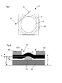
- FIG. 1 shows an optoelectronic sensor 1 with a housing 22, a windscreen 24 and an electrical connection 26.
- Such optoelectronic sensors 1 are formed as a light barrier, reflection light barrier, light scanner, rangefinder.
- at least one light transmitter and / or at least one light receiver are arranged in the housing 22, which are connected to an electronic control and evaluation unit.
- optical components are arranged behind the front screen 24 inside the housing. The light rays reach the light receiver for object detection after a remission or reflection on an object through the windshield.
- the housing 22 may be made of plastic or stainless steel.
- For the windscreen 24 usually a plastic disc or a glass sheet is used.
- like parts are given identical reference numerals.
- FIG. 2 shows a base support 20 for the optics carrier 2.
- the base support 20 has in this embodiment, a square or rectangular basic shape. However, other forms of the base support 20 are conceivable.
- On two opposite sides of the basic carrier is one each Attachment 32 provided as a fastener 28 for a not shown clamping part.
- FIG. 3 shows the base support 20 from FIG. 2 with an optical component 6 disposed on the base support 20 as the first element 3.
- the optical component 6 may be, for example, a refractive optical element, a lens 8, a plastic lens, a double lens, a diffractive optical element, or another optical component.
- the optical component 6 has at least two retaining projections 12. In the example shown, four holding projections 12 are arranged at equal distances from each other on the circumference of the optical component 6. It is also conceivable to arrange three or more than four holding projections 12. However, a number of at least three to a maximum of ten retaining projections 12 is optimal, in particular three to six, and particularly preferably four retaining projections 12.
- the optical component 6 can in this case with the retaining projections 12 and / or directly with the edge of the optical component 6 on the base support 20th rest.
- the optical component 6 has a projection which engages in the opening of the base support 20, whereby the optical component 6 is secured against radial displacement.
- FIG. 6a the optical component 6 with the projection 30 is shown in a perspective view.
- FIG. 4 shows the optics carrier 2 FIG. 3 with additionally arranged annular elastic compensation element 4.
- the elastic compensation element 4 is arranged around the optical component 6 around.
- the elastic compensation element 4 is held by a clamping force in the radial direction on the optical component 6.
- FIG. 6a the arrangement of the elastic compensation element 4 on the optical component 6 is shown in perspective.
- the elastic compensation element 4 rests on the optical component 6 above the retaining projections 12.
- FIG. 5 shows the optics carrier 2 FIG. 4 with additionally arranged clamping part 16 as the second element 5.
- the clamping part 16 is via the optical component. 6 slipped with the elastic compensation element 4 and then pressed in the axial direction to the optical component 6 in the direction of the elastic compensation element 4.
- the clamping part may be made of plastic or metal, for example spring steel, or spring bronze.
- the snap devices 18 of the clamping part engage in the fastening receptacle 32 of the base support 20, whereby the clamping part is fastened.
- the optical component is held by the elastic compensation element 4.
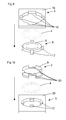
- FIG. 6 shows the optical carrier 2 with the base support 20, the optical component 6 as a first element 3, the elastic compensation element 4 and the clamping member 16 as a second element 5 in a schematic exploded drawing.
- FIG. 6 shows the sequence of assembly of the individual components for the optical carrier 2.
- the optical component 6 is inserted.
- the elastic compensation element 4 is attached to the optical component 6.
- the elastic compensation element 4 is located, wherein the retaining projections protrude from the support plane 7 of the elastic compensation element 4.
- the arranged on the optical component 6 elastic compensation element 4 is in FIG. 6a explicitly shown in perspective.
- the retaining projections 12 of the optical component 6 are executed rounded.
- the retaining projections 12 project from a supporting plane 7 of the annular elastic compensating element 4. It is also possible first to attach the elastic compensating element 4 to the optical component 6 and then to insert the optical component 6 into the basic carrier 20. Finally, the clamping member 16 is then placed on the base support 20 with the optical component 6 and the elastic compensation element 4 and snapped with the snap devices 18 in the mounting receptacle 32.
- FIG. 6b shows the optics carrier 2 finally mounted with the in FIG. 6 shown and described components.
- the elastic compensation element 4 projects in sections into the compensation openings 10 of the clamping part 16.
- FIG. 7 shows a schematic plan view of the final mounted optical carrier 2 FIG. 6b , A section along the line AA is in FIG. 8 shown.
- FIG. 8 shows a schematic sectional view along the line AA FIG. 7 ,
- the retaining projection 12 in this case has the height g.
- the elastic compensation element 4 is pressed against the base support 20.
- the clamping member 16 is shown in the snapped final position, wherein a clamping measure is indicated by the reference numeral k.
- An elasticity measure is indicated by the reference symbol s.
- a clamping region is indicated by the reference I.
- the elastic compensation element 4 is thereby pressed by the holding projection 12 into the compensation opening 10 with the size f of the clamping part 16.
- the holding force can be done by dimensioning the size of the retaining projections 12, the diameter of the cross section of the elastic compensation element 4 and / or the dimensions or compensation opening 10 in relation to the respective retaining projection 12.
- the clamping part 16 has the compensation opening 10 at these points.
- a part of the clamping of the elastic compensating element 4 is replaced by an elongation, whereby more tolerances can be compensated.
- the material thickness of the clamping member 16 is space-saving for the partial absorption of the elastic compensation element. 4 shared. Due to the size f of the compensation opening 10, the male tolerance window and the hold-down force of the clamping part 16 can be designed.
- FIGS. 9 to 12 show schematically simplified further embodiments of the invention.
- the embodiments according to the FIGS. 1 to 12 can be combined arbitrarily.
- the clamping part 16 forms the first element 3.
- the clamping part 16 has a number, namely four equalization openings 10.
- the optical component 6 is shown with a number, namely four retaining projections 12.
- the holding projections 12 are associated with the compensation openings 10 arranged.
- the clamping part 16 has an opening for the passage of light rays.
- the fastening means may be arranged on the clamping part 16 and / or on the optical component 6 in order to fix and fix the position between the clamping part 16 and the optical component 6.
- the optical component 6 forms the first element 3.
- the optical component 6 has compensation openings 10.
- a base support 20 is shown.
- the base support 20 has holding projections 12, which are arranged to the compensation openings 10 associated.
- the base support 20 has an opening for the passage of light rays.
- the fastening means may be attached to the optical component 6 and / or to the base support 20 according to this embodiment.
- FIG. 11 shows an optical carrier consisting of the clamping member 16 as a first element with the retaining projections 12. Further, as the second element 5, the optical component 6 is shown with the compensation openings 10, which to the Holding projections 12 are associated. Between the clamping part 16 and the optical component 6, the annular elastic compensation element 4 is clamped. According to this embodiment, the fastening means may be arranged on the clamping part 16 and / or on the optical component 6.
- FIG. 12 shows an optical carrier consisting of an optical component 6 as a first element 3 with the retaining projections 12. Furthermore, the optical carrier from the base support 20 as a second element 5 with the compensation openings 10. Between the base support 20 and the optical component 6 in turn, the annular elastic compensation element 4 braces, as already described in the figures above.
Abstract
Description
Die vorliegende Erfindung betrifft einen Optikträger für einen optoelektronischen Sensor und ein Verfahren zur Montage des Optikträgers.The present invention relates to an optical carrier for an optoelectronic sensor and a method for mounting the optical carrier.
Bekannt sind Optikträger, welche in einem Gehäuse einer optoelektronischen Sensoranordnung eingesetzt werden, um ein optisches Element und ein zugehöriges Sende- und/oder Empfangselement bzw. die zugehörige Sende- und Empfangselektronik der optoelektronischen Sensoranordnung relativ zueinander zu positionieren. Dazu weist der Optikträger wenigstens eine Klemmfeder und wenigstens ein Gegenlager auf, wobei zwischen der wenigstens einen Klemmfeder und dem wenigstens einen Gegenlager das optische Element klemmbar ist.Optical carriers are known which are used in a housing of an optoelectronic sensor arrangement in order to position an optical element and an associated transmitting and / or receiving element or the associated transmitting and receiving electronics of the optoelectronic sensor arrangement relative to one another. For this purpose, the optics carrier has at least one clamping spring and at least one abutment, wherein between the at least one clamping spring and the at least one abutment, the optical element is clamped.
Bei den bekannten Optikträgern sind die Klemmfeder und das Gegenlager in einem Teil integriert und somit in ihrer relativen Lage zueinander fixiert. Um eine exakte Positionierung zu ermöglichen, müssen die Klemmfeder und das Gegenlager mit hoher Genauigkeit gefertigt werden, was hohe Herstellkosten, insbesondere hohe Werkzeugkosten, zur Folge hat. Trotzdem können oft inakzeptable Toleranzen auftreten. Zudem ist das Klemmmaß für das optische Element durch die Integration von Klemmfeder und Gegenlager in einen einteiligen Optikträger begrenzt, was dazu führt, dass eine Lockerung des Sitzes des optischen Elements auftreten kann.In the known optical carriers, the clamping spring and the abutment are integrated in one part and thus fixed in their relative position to each other. In order to enable an exact positioning, the clamping spring and the counter bearing must be manufactured with high accuracy, which has high production costs, in particular high tooling costs result. Nevertheless, unacceptable tolerances can often occur. In addition, the clamping dimension for the optical element is limited by the integration of clamping spring and counter bearing in a one-piece optical carrier, which leads to a loosening of the seat of the optical element may occur.
Bekannt ist weiter die Befestigung einer Linse durch Kleben. Dies bedingt jedoch einen aufwändigen Fügeprozess und es besteht die Gefahr, dass der Klebstoff auf die optischen Teile gelangt und die Funktion der Optik negativ beeinflusst.It is also known to attach a lens by gluing. However, this requires a complex joining process and there is a risk that the adhesive gets onto the optical parts and adversely affects the function of the optics.
Weiter ist es bekannt eine Linse durch Schweißen, schrauben oder Verstemmen zu befestigen. Diese Verfahren erfordern jedoch viel Platz auf einem Optikträger, der meist nicht zur Verfügung steht. Weiter verursachen diese Verfahren aufwändige Fertigungsprozesse und schränken die Werkstoffauswahl ein.Further, it is known to attach a lens by welding, screwing or caulking. However, these methods require a lot of space on an optical carrier, which is usually not available. Furthermore, these processes cause complex manufacturing processes and restrict the choice of materials.
Die
In der
Die Aufgabe besteht darin, eine vereinfachte Befestigung eines optischen Elements bereitzustellen, die wenig Bauraum beansprucht und größere Toleranzen für die notwendigen Komponenten ermöglicht.The object is to provide a simplified attachment of an optical element that takes up little space and allows greater tolerances for the necessary components.
Die Aufgabe wird gelöst durch einen Optikträger mit einem ersten Element, einem ringförmigen elastischen Ausgleichselement und einem zweiten Element, wobei das elastische Ausgleichselement zwischen dem ersten und dem zweiten Element angeordnet ist und das erste Element oder das zweite Element eine optische Komponente ist, die gegen das andere Element unter Vorspannung des elastischen Ausgleichselements festlegbar ist, wobei das erste Element mindestens zwei Haltevorsprünge aufweist und das zweite Element zu den Haltevorsprüngen zugehörige Ausgleichsöffnungen aufweist, wobei die Haltevorsprünge aus einer Auflageebene des elastischen Ausgleichselements hervorstehen und bei Festlegung der Elemente zueinander das elastische Ausgleichselement bei unveränderter radialer Position in Längsrichtung gedehnt ist.The object is achieved by an optical carrier having a first element, an annular elastic compensation element and a second element, wherein the elastic compensation element between the first and the second element is arranged and the first element or the second element is an optical component which is against the another element under bias of the elastic compensating element can be fixed, wherein the first element has at least two retaining projections and the second element to the retaining projections associated compensation openings, wherein the retaining projections project from a support plane of the elastic compensation element and when fixing the elements to each other, the elastic compensation element at unchanged Radial position is stretched in the longitudinal direction.
Die Aufgabe wird weiter durch ein Verfahren mit den Merkmalen nach Anspruch 7 gelöst.The object is further achieved by a method having the features of
Ein Federweg des elastischen Ausgleichselements liegt beispielsweise bei einem O-Ring als elastisches Ausgleichselement, üblicherweise bei ca. 15% des Querschnittdurchmessers. Das bedeutet, dass unter Berücksichtigung einer Mindestverpressung von 5% nur noch 10% für den Toleranzausgleich verbleiben. Je dünner der Querschnittsdurchmesser des elastischen Ausgleichselements, desto geringer ist der mögliche Toleranzausgleich, was bei einer Miniaturisierung ein Problem darstellt. Der Anpressdruck wird über die Härte des elastischen Ausgleichselements eingestellt.A spring travel of the elastic compensating element is, for example, in the case of an O-ring as an elastic compensating element, usually about 15% of the cross-sectional diameter. This means that, taking into account a minimum compression of 5%, only 10% remains for the tolerance compensation. The thinner the cross-sectional diameter of the elastic compensating element, the lower the possible tolerance compensation, which is a problem in miniaturization. The contact pressure is adjusted by the hardness of the elastic compensation element.
Gemäß der Erfindung wird durch die Ausgleichsöffnung ein Federweg des ringförmigen elastischen Ausgleichselements verlängert. Mit der vorliegenden Erfindung ist es nun möglich diese oben beschriebene Begrenzung zu vermeiden, indem der elastische Weg nicht nur durch das elastische Ausgleichselement selbst bestimmt wird, sondern auch durch die Abmessungen der Ausgleichsöffnung und durch die Höhe der Haltevorsprünge.According to the invention, a spring travel of the annular elastic compensation element is extended by the compensation opening. With the present invention, it is now possible to avoid this limitation described above, by the elastic path is determined not only by the elastic compensation element itself, but also by the dimensions of the compensation opening and by the height of the retaining projections.
Durch die erfindungsgemäße Vorrichtung wird die optische Komponente präzise positioniert. Durch die vorgesehenen Haltevorsprünge und die korrespondierenden Ausgleichsöffnungen wird die optische Komponente nur an einzelnen Punkten gespannt. Das elastische Ausgleichselement wird dabei durch den Haltevorsprung in die Ausgleichsöffnung gedehnt und ragt dabei in die Ausgleichsöffnung. Durch die Dehnung können mehr Toleranzen aufgenommen werden als bei einer flächigen Verpressung des elastischen Ausgleichselements. Neben der Dehnung ist auch eine Kombination von Dehnung und Verpressung möglich, bei der zusätzlich das elastische Ausgleichselement zwischen dem ersten Element und dem zweiten Element, zumindest abschnittsweise verpresst wird.By the device according to the invention, the optical component is precisely positioned. Due to the provided holding projections and the corresponding compensation openings, the optical component is tensioned only at individual points. The elastic compensation element is thereby stretched by the holding projection in the compensation opening and protrudes into the compensation opening. By stretching more tolerances can be absorbed than with a flat compression of the elastic compensation element. In addition to the expansion, a combination of elongation and compression is possible, in which in addition the elastic compensation element between the first element and the second element, at least partially compressed.
Die Ausgleichsöffnungen sind dabei weiter oder größer als die Haltevorsprünge ausgebildet. Dadurch ist zwischen dem Haltevorsprung und dem Rand der Ausgleichsöffnung Platz für einen Federweg des elastischen Ausgleichselements.The compensation openings are formed wider or larger than the retaining projections. As a result, there is space for a spring travel of the elastic compensation element between the retaining projection and the edge of the compensation opening.
Die Haltevorsprünge sind radial zu einer optischen Achse der optischen Komponente ausgedehnt. Die Haltevorsprünge befinden sich dabei beispielsweise seitlich an der optischen Komponente. Durch die radial angeordneten Haltevorsprünge ist eine kompakte Bauform des ersten oder zweiten Elements und eine gute Kräfteverteilung auf die Haltevorsprünge gewährleistet.The retaining projections are extended radially to an optical axis of the optical component. The retaining projections are for example on the side of the optical component. The radially arranged retaining projections ensure a compact design of the first or second element and a good distribution of forces on the retaining projections.
Durch die erfindungsgemäße Lösung ist die optische Komponente zusätzlich gegen ein Verdrehen gesichert. Dadurch, dass das elastische Ausgleichselement durch die Haltevorsprünge in die Ausgleichsöffnungen gedrückt wird und somit in die Ausgleichsöffnung ragt, entsteht eine Verrastung zwischen den Haltevorsprüngen und den Ausgleichsöffnungen, wodurch die optische Komponente gegen eine Verdrehung gesichert ist.The inventive solution, the optical component is additionally secured against rotation. Characterized in that the elastic compensation element is pressed by the retaining projections in the compensation openings and thus projects into the compensation opening, a latching between the retaining projections and the compensation openings, whereby the optical component is secured against rotation.
In Weiterbildung der Erfindung ist das erste Element oder das zweite Element ein Grundträger oder ein Klemmteil. Der Grundträger oder das Klemmteil weist beispielsweise eine Referenzfläche auf, die definierte Abstände aufweist zu den Sende- und/oder Empfangselementen. Dadurch wird die optische Komponente automatisch zu einem Sende- und/oder Empfangselement positioniert.In a further development of the invention, the first element or the second element is a basic carrier or a clamping part. The base carrier or the clamping part has, for example, a reference surface which has defined distances to the transmitting and / or receiving elements. As a result, the optical component is automatically positioned to a transmitting and / or receiving element.
In einer bevorzugten Ausführungsform der Erfindung weist der Grundträger und/oder das Klemmteil vorzugsweise eine Öffnung für Lichtstrahlen auf. Durch die Öffnung können die Lichtstrahlen durch den Grundträger oder das Klemmteil gelangen. Dadurch kann der Grundträger oder das Klemmteil die optische Komponente vollumfänglich umschließen, wodurch eine höhere Stabilität, insbesondere Verwindungssteifigkeit entsteht.In a preferred embodiment of the invention, the base support and / or the clamping part preferably has an opening for light rays. Through the opening, the light rays can pass through the base support or the clamping part. As a result, the basic carrier or the clamping part can completely enclose the optical component, resulting in a higher stability, in particular torsional rigidity.
In einer bevorzugten Ausführungsform ist die optische Komponente als Linse ausgebildet. Durch eine einzige Linse pro Sendelement oder Empfangselement ist die optische Komponente sehr einfach und kompakt ausgebildet. Die Linse ist dabei vorzugsweise als Sammellinse ausgebildet, um ein Lichtstrahlenbündel oder einen Lichtstrahlkegel zu erzeugen oder empfangenes Licht auf ein Empfangselement zu fokussieren. Die Linse kann auch vorgesehen sein, um einen Laserstrahl zu bündeln.In a preferred embodiment, the optical component is designed as a lens. By a single lens per transmitting element or receiving element, the optical component is very simple and compact. The lens is preferably designed as a converging lens to produce a light beam or a cone of light rays or to focus received light onto a receiving element. The lens may also be provided to focus a laser beam.
In Weiterbildung der Erfindung weist das erste Element und/oder das zweite Element mindestens ein Befestigungsmittel auf. Durch das Befestigungsmittel kann das erste und zweite Element direkt miteinander verbunden und arretiert werden ohne dass zusätzliche Komponenten notwendig sind. Die Befestigungsmittel können in dem ersten oder zweiten Element direkt integriert sein, beispielsweise einstückig mit dem ersten und oder zweiten Element gebildet sein. Durch die Befestigungsmittel kann auch gleichzeitig die finale Position zwischen dem ersten Element und dem zweiten Element vorgegeben werden.In a development of the invention, the first element and / or the second element has at least one fastening means. By the fastening means, the first and second elements can be directly connected and locked together without additional components are necessary. The fastening means may be directly integrated in the first or second element, for example formed integrally with the first and or second element. The fastening means can also be used to specify the final position between the first element and the second element at the same time.
In Weiterbildung der Erfindung ist das Befestigungsmittel durch eine Schnappvorrichtung gebildet. Durch die Schnappvorrichtung wird beispielsweise das Klemmteil einfach durch einen Schnappmechanismus an dem Grundträger befestigt. Durch die Schnappvorrichtung entfallen weitere Befestigungsteile. Sobald das erste oder zweite Element, beispielsweise das Klemmteil, die vorgesehene Position erreicht hat, rastet die Schnappvorrichtung ein und das Klemmteil ist an dem Grundträger befestigt und genau arretiert. Eine Schnappvorrichtung hat den Vorteil, dass diese bei einer final zu ereichenden Position zwischen dem ersten und dem zweiten Element selbstständig arretiert wird. So ist eine sichere Positionierung des ersten und zweiten Elements zueinander gewährleistet.In a further development of the invention, the fastening means is formed by a snap device. By the snap device, for example, the clamping member is simply attached by a snap mechanism to the base support. The snap device eliminates further fasteners. As soon as the first or second element, for example the clamping part, has reached the intended position, the snap-in device engages and the clamping part is fastened to the basic carrier and precisely locked. A snap device has the advantage that it is automatically locked at a final position to be reached between the first and the second element. This ensures secure positioning of the first and second elements relative to one another.
Im Folgenden wird die Erfindung anhand von Ausführungsbeispielen unter Bezugnahme auf die Zeichnung im Einzelnen erläutert.In the following the invention will be explained in detail by means of embodiments with reference to the drawing.
In der Zeichnung zeigt:
-
Figur 1 -
Figur 2 -
Figur 3 -
Figur 4 -
Figur 5 -
Figur 6 -
Figuren 6a und 6b einzelnen Teile des Optikträgers. -
Figur 7Figur 8 -
Figuren 9 weitere Ausführungsbeispiele von Optikträgern.bis 12
-
FIG. 1 an optoelectronic sensor; -
FIG. 2 a basic carrier; -
FIG. 3 the basic carrier with optical component; -
FIG. 4 the optical carrier with elastic compensation element; -
FIG. 5 the optical carrier with clamping part; -
FIG. 6 the optical carrier with the sequence for mounting the individual components; -
Figures 6a and 6b individual parts of the optics carrier. -
FIG. 7 the optics carrier in a plan view andFIG. 8 a section through the optics carrier; -
FIGS. 9 to 12 further embodiments of optical carriers.
Das auf der optischen Komponente 6 angeordnete elastische Ausgleichselement 4 ist in
Um zu vermeiden, dass durch die Klemmung entstehende Kräfte zu hoch werden, wird die optische Komponente nicht flächendeckend, sondern nur über einzelne Punkte gespannt. Das Klemmteil 16 weist an diesen Punkten die Ausgleichsöffnung 10 auf. Durch diese Maßnahme wird ein Teil der Klemmung des elastischen Ausgleichselements 4 durch eine Dehnung ersetzt, wodurch mehr Toleranzen kompensiert werden können. Die Materialstärke des Klemmteils 16 wird raumsparend für die teilweise Aufnahme des elastischen Ausgleichselements 4 mitgenutzt. Durch die Größe f der Ausgleichsöffnung 10 kann das aufzunehmende Toleranzfenster und die Niederhaltekraft des Klemmteils 16 ausgelegt werden.In order to avoid that forces resulting from the clamping become too high, the optical component is not stretched across the surface but only stretched over individual points. The clamping
Gemäß
Gemäß
- 11
- optoelektronische Sensor.optoelectronic sensor.
- 22
- Optikträgeroptics carrier
- 33
- erstes Elementfirst element
- 44
- elastisches Ausgleichselementelastic compensation element
- 55
- zweites Elementsecond element
- 66
- optische Komponenteoptical component
- 77
- Auflageebenesupport plane
- 88th
- Linselens
- 1010
- Ausgleichsöffnungencompensation openings
- 1212
- Haltevorsprungretaining projection
- 1616
- Klemmteilclamping part
- 1818
- Schnappvorrichtungsnap device
- 2020
- Grundträgerbase support
- 2222
- Gehäusecasing
- 2424
- Frontscheibewindscreen
- 2626
- elektrischer Anschlusselectrical connection
- 2828
- Befestigungsmittelfastener
- 3030
- Vorsprunghead Start
- 3232
- Befestigungsaufnahmemounting fixture
- kk
- Klemmmaßclamping dimension
- ll
- Klemmbereichclamping range
- ss
- Elastizitätsmaßmodulus of elasticity
- ff
- Breite oder Weite der AusgleichsöffnungWidth or width of the compensation opening
- gG
- Höhe des HaltevorsprungsHeight of the retaining projection
Claims (7)
dass das erste Element (3) mindestens zwei Haltevorsprünge (12) aufweist und das zweite Element (5) zu den Haltevorsprüngen (12) zugehörige Ausgleichsöffnungen (10) aufweist, wobei die Haltevorsprünge (12) aus einer Auflageebene (7) des elastischen Ausgleichselements (4) hervorstehen und bei Festlegung der Elemente (3, 5) zueinander das elastische Ausgleichselement (4) bei unveränderter radialer Position in Längsrichtung gedehnt ist.Optical support with a first element (3), an annular elastic compensation element (4) and a second element (5), wherein the elastic compensation element (4) between the first and the second element (3, 5) is arranged and the first element ( 3) or the second element (5) is an optical component (6) which is fixable against the other element under bias of the elastic compensating element (4), characterized
in that the first element (3) has at least two holding projections (12) and the second element (5) has compensating openings (10) associated with the holding projections (12), wherein the holding projections (12) consist of a support plane (7) of the elastic compensating element (10). 4) protrude and when fixing the elements (3, 5) to each other, the elastic compensation element (4) is stretched in the radial direction unchanged in the longitudinal direction.
dadurch gekennzeichnet,
dass das erste Element (3) mindestens zwei Haltevorsprünge (12) aufweist und das zweite Element (5) zu den Haltevorsprüngen (12) zugehörige Ausgleichsöffnungen (10) aufweist, wobei die Haltevorsprünge aus einer Auflageebene des elastischen Ausgleichselements (4) hervorstehen und bei Festlegung der Element (3, 5) zueinander das elastische Ausgleichselement (4) bei unveränderter radialer Position in Längsrichtung gedehnt wird.Method for mounting an optical carrier with a first element (3), an annular elastic compensation element (4) and a second element (5), wherein the elastic compensation element (4) between the first and the second element (3, 5) is arranged and the first element (3) or the second element (5) is an optical component (6) which is fixed against the other element under bias of the elastic compensating element (4),
characterized,
in that the first element (3) has at least two holding projections (12) and the second element (5) has compensation openings (10) associated with the holding projections (12), the holding projections protruding from a support plane of the elastic compensating element (4) and when fixed the element (3, 5) to each other, the elastic compensation element (4) is stretched in the radial direction in the longitudinal direction unchanged.
Applications Claiming Priority (1)
| Application Number | Priority Date | Filing Date | Title |
|---|---|---|---|
| DE201110002299 DE102011002299A1 (en) | 2011-04-28 | 2011-04-28 | optics carrier |
Publications (2)
| Publication Number | Publication Date |
|---|---|
| EP2530351A1 true EP2530351A1 (en) | 2012-12-05 |
| EP2530351B1 EP2530351B1 (en) | 2015-01-21 |
Family
ID=46298228
Family Applications (1)
| Application Number | Title | Priority Date | Filing Date |
|---|---|---|---|
| EP20120165230 Active EP2530351B1 (en) | 2011-04-28 | 2012-04-23 | Lens holder |
Country Status (2)
| Country | Link |
|---|---|
| EP (1) | EP2530351B1 (en) |
| DE (1) | DE102011002299A1 (en) |
Cited By (2)
| Publication number | Priority date | Publication date | Assignee | Title |
|---|---|---|---|---|
| CN106195934A (en) * | 2016-08-23 | 2016-12-07 | 惠州市华阳多媒体电子有限公司 | A kind of fixed structure of HUD illuminating spotlight mirror |
| US11934031B2 (en) * | 2018-04-09 | 2024-03-19 | Canon Kabushiki Kaisha | Lens apparatus and optical apparatus including same |
Families Citing this family (1)
| Publication number | Priority date | Publication date | Assignee | Title |
|---|---|---|---|---|
| EP3098652B1 (en) * | 2015-05-27 | 2017-11-08 | Axis AB | Mounting system for a camera and a camera |
Citations (5)
| Publication number | Priority date | Publication date | Assignee | Title |
|---|---|---|---|---|
| GB2058389A (en) * | 1979-08-29 | 1981-04-08 | Hoya Corp | Optical filter |
| DE3521640C2 (en) | 1985-06-15 | 1992-12-03 | Optische Werke G. Rodenstock, 8000 Muenchen, De | |
| DE69322822T2 (en) | 1992-08-12 | 1999-07-29 | Bayer Ag | Conical lens mount with snap-in clamping device |
| EP1174748A2 (en) * | 2000-07-17 | 2002-01-23 | Kabushiki Kaisha Toshiba | Optical lens unit having a mechanism for adjusting the focal point of the optical lens |
| US20060044455A1 (en) * | 2004-09-02 | 2006-03-02 | Samsung Electro-Mechanics Co., Ltd. | Lens-positioning device of camera module |
-
2011
- 2011-04-28 DE DE201110002299 patent/DE102011002299A1/en not_active Withdrawn
-
2012
- 2012-04-23 EP EP20120165230 patent/EP2530351B1/en active Active
Patent Citations (5)
| Publication number | Priority date | Publication date | Assignee | Title |
|---|---|---|---|---|
| GB2058389A (en) * | 1979-08-29 | 1981-04-08 | Hoya Corp | Optical filter |
| DE3521640C2 (en) | 1985-06-15 | 1992-12-03 | Optische Werke G. Rodenstock, 8000 Muenchen, De | |
| DE69322822T2 (en) | 1992-08-12 | 1999-07-29 | Bayer Ag | Conical lens mount with snap-in clamping device |
| EP1174748A2 (en) * | 2000-07-17 | 2002-01-23 | Kabushiki Kaisha Toshiba | Optical lens unit having a mechanism for adjusting the focal point of the optical lens |
| US20060044455A1 (en) * | 2004-09-02 | 2006-03-02 | Samsung Electro-Mechanics Co., Ltd. | Lens-positioning device of camera module |
Cited By (2)
| Publication number | Priority date | Publication date | Assignee | Title |
|---|---|---|---|---|
| CN106195934A (en) * | 2016-08-23 | 2016-12-07 | 惠州市华阳多媒体电子有限公司 | A kind of fixed structure of HUD illuminating spotlight mirror |
| US11934031B2 (en) * | 2018-04-09 | 2024-03-19 | Canon Kabushiki Kaisha | Lens apparatus and optical apparatus including same |
Also Published As
| Publication number | Publication date |
|---|---|
| DE102011002299A1 (en) | 2012-10-31 |
| EP2530351B1 (en) | 2015-01-21 |
Similar Documents
| Publication | Publication Date | Title |
|---|---|---|
| EP2050281B1 (en) | Optical measurement device with two camera units | |
| EP2865174B1 (en) | Camera module for a vehicle, and method for producing same | |
| DE102006058805B4 (en) | Device for the input of movements and / or detection of forces | |
| DE112017005837B4 (en) | MOUNTING STRUCTURE FOR AN ON-VEHICLE ELECTRONIC UNIT | |
| DE102018203399A1 (en) | rotary encoder | |
| EP2736769B1 (en) | Fixing device for fixing a sensor in a fastening device of a motor vehicle | |
| DE102013102819A1 (en) | Camera module and method of manufacture | |
| EP2530351B1 (en) | Lens holder | |
| DE102015225794B4 (en) | Adjustment element for a camera module, adjustment device and method for setting an axial distance | |
| EP2560038B1 (en) | Holder for optical element and assembly method | |
| EP1668891B1 (en) | Image recording system | |
| DE102006008230B4 (en) | Imaging system | |
| WO2007124994A1 (en) | Optical module, and method for the production of an optical module | |
| EP1651981B1 (en) | Device for adjusting an optical mirror | |
| DE202016104891U1 (en) | Connector housing and connectors | |
| DE102007055497B4 (en) | Optical sensor for a motor vehicle | |
| DE4142108C2 (en) | Mounting structure for an optical component of an optical device | |
| WO2020207536A1 (en) | Adjustment mount for radial adjustment of an optical unit having an optical axis | |
| DE102009056659B4 (en) | Lens for a semiconductor camera and method for focusing a semiconductor camera | |
| DE102013102225A1 (en) | mirror Mounts | |
| DE102017209286B3 (en) | Camera module for a vehicle, camera system and method for producing a camera module | |
| DE102021130506A1 (en) | Light module for a motor vehicle headlight and fastening of components of the light module | |
| DE602004004003T2 (en) | Mounting arrangement for fixing windshield wiper drive devices | |
| DE102019132908A1 (en) | Holding device for holding a camera on a window of a motor vehicle and motor vehicle with a holding device | |
| DE10200543B4 (en) | Apparatus and method for attaching a character generator by means of adjusting devices |
Legal Events
| Date | Code | Title | Description |
|---|---|---|---|
| PUAI | Public reference made under article 153(3) epc to a published international application that has entered the european phase |
Free format text: ORIGINAL CODE: 0009012 |
|
| AK | Designated contracting states |
Kind code of ref document: A1 Designated state(s): AL AT BE BG CH CY CZ DE DK EE ES FI FR GB GR HR HU IE IS IT LI LT LU LV MC MK MT NL NO PL PT RO RS SE SI SK SM TR |
|
| AX | Request for extension of the european patent |
Extension state: BA ME |
|
| 17P | Request for examination filed |
Effective date: 20130111 |
|
| RBV | Designated contracting states (corrected) |
Designated state(s): AL AT BE BG CH CY CZ DE DK EE ES FI FR GB GR HR HU IE IS IT LI LT LU LV MC MK MT NL NO PL PT RO RS SE SI SK SM TR |
|
| 17Q | First examination report despatched |
Effective date: 20131125 |
|
| REG | Reference to a national code |
Ref country code: DE Ref legal event code: R079 Ref document number: 502012002149 Country of ref document: DE Free format text: PREVIOUS MAIN CLASS: F16F0001373000 Ipc: G02B0007020000 |
|
| GRAP | Despatch of communication of intention to grant a patent |
Free format text: ORIGINAL CODE: EPIDOSNIGR1 |
|
| RIC1 | Information provided on ipc code assigned before grant |
Ipc: F16F 1/373 20060101ALI20140915BHEP Ipc: G02B 7/02 20060101AFI20140915BHEP Ipc: F21V 17/16 20060101ALI20140915BHEP Ipc: G02B 7/00 20060101ALI20140915BHEP |
|
| INTG | Intention to grant announced |
Effective date: 20141020 |
|
| GRAS | Grant fee paid |
Free format text: ORIGINAL CODE: EPIDOSNIGR3 |
|
| GRAA | (expected) grant |
Free format text: ORIGINAL CODE: 0009210 |
|
| AK | Designated contracting states |
Kind code of ref document: B1 Designated state(s): AL AT BE BG CH CY CZ DE DK EE ES FI FR GB GR HR HU IE IS IT LI LT LU LV MC MK MT NL NO PL PT RO RS SE SI SK SM TR |
|
| REG | Reference to a national code |
Ref country code: GB Ref legal event code: FG4D Free format text: NOT ENGLISH |
|
| REG | Reference to a national code |
Ref country code: CH Ref legal event code: EP |
|
| REG | Reference to a national code |
Ref country code: IE Ref legal event code: FG4D Free format text: LANGUAGE OF EP DOCUMENT: GERMAN |
|
| REG | Reference to a national code |
Ref country code: DE Ref legal event code: R096 Ref document number: 502012002149 Country of ref document: DE Effective date: 20150312 |
|
| REG | Reference to a national code |
Ref country code: AT Ref legal event code: REF Ref document number: 709434 Country of ref document: AT Kind code of ref document: T Effective date: 20150315 |
|
| REG | Reference to a national code |
Ref country code: NL Ref legal event code: VDEP Effective date: 20150121 |
|
| REG | Reference to a national code |
Ref country code: LT Ref legal event code: MG4D |
|
| PG25 | Lapsed in a contracting state [announced via postgrant information from national office to epo] |
Ref country code: ES Free format text: LAPSE BECAUSE OF FAILURE TO SUBMIT A TRANSLATION OF THE DESCRIPTION OR TO PAY THE FEE WITHIN THE PRESCRIBED TIME-LIMIT Effective date: 20150121 Ref country code: LT Free format text: LAPSE BECAUSE OF FAILURE TO SUBMIT A TRANSLATION OF THE DESCRIPTION OR TO PAY THE FEE WITHIN THE PRESCRIBED TIME-LIMIT Effective date: 20150121 Ref country code: SE Free format text: LAPSE BECAUSE OF FAILURE TO SUBMIT A TRANSLATION OF THE DESCRIPTION OR TO PAY THE FEE WITHIN THE PRESCRIBED TIME-LIMIT Effective date: 20150121 Ref country code: BG Free format text: LAPSE BECAUSE OF FAILURE TO SUBMIT A TRANSLATION OF THE DESCRIPTION OR TO PAY THE FEE WITHIN THE PRESCRIBED TIME-LIMIT Effective date: 20150421 Ref country code: HR Free format text: LAPSE BECAUSE OF FAILURE TO SUBMIT A TRANSLATION OF THE DESCRIPTION OR TO PAY THE FEE WITHIN THE PRESCRIBED TIME-LIMIT Effective date: 20150121 Ref country code: FI Free format text: LAPSE BECAUSE OF FAILURE TO SUBMIT A TRANSLATION OF THE DESCRIPTION OR TO PAY THE FEE WITHIN THE PRESCRIBED TIME-LIMIT Effective date: 20150121 Ref country code: NO Free format text: LAPSE BECAUSE OF FAILURE TO SUBMIT A TRANSLATION OF THE DESCRIPTION OR TO PAY THE FEE WITHIN THE PRESCRIBED TIME-LIMIT Effective date: 20150421 |
|
| PG25 | Lapsed in a contracting state [announced via postgrant information from national office to epo] |
Ref country code: GR Free format text: LAPSE BECAUSE OF FAILURE TO SUBMIT A TRANSLATION OF THE DESCRIPTION OR TO PAY THE FEE WITHIN THE PRESCRIBED TIME-LIMIT Effective date: 20150422 Ref country code: NL Free format text: LAPSE BECAUSE OF FAILURE TO SUBMIT A TRANSLATION OF THE DESCRIPTION OR TO PAY THE FEE WITHIN THE PRESCRIBED TIME-LIMIT Effective date: 20150121 Ref country code: IS Free format text: LAPSE BECAUSE OF FAILURE TO SUBMIT A TRANSLATION OF THE DESCRIPTION OR TO PAY THE FEE WITHIN THE PRESCRIBED TIME-LIMIT Effective date: 20150521 Ref country code: PL Free format text: LAPSE BECAUSE OF FAILURE TO SUBMIT A TRANSLATION OF THE DESCRIPTION OR TO PAY THE FEE WITHIN THE PRESCRIBED TIME-LIMIT Effective date: 20150121 Ref country code: LV Free format text: LAPSE BECAUSE OF FAILURE TO SUBMIT A TRANSLATION OF THE DESCRIPTION OR TO PAY THE FEE WITHIN THE PRESCRIBED TIME-LIMIT Effective date: 20150121 Ref country code: RS Free format text: LAPSE BECAUSE OF FAILURE TO SUBMIT A TRANSLATION OF THE DESCRIPTION OR TO PAY THE FEE WITHIN THE PRESCRIBED TIME-LIMIT Effective date: 20150121 |
|
| REG | Reference to a national code |
Ref country code: DE Ref legal event code: R097 Ref document number: 502012002149 Country of ref document: DE |
|
| PG25 | Lapsed in a contracting state [announced via postgrant information from national office to epo] |
Ref country code: EE Free format text: LAPSE BECAUSE OF FAILURE TO SUBMIT A TRANSLATION OF THE DESCRIPTION OR TO PAY THE FEE WITHIN THE PRESCRIBED TIME-LIMIT Effective date: 20150121 Ref country code: DK Free format text: LAPSE BECAUSE OF FAILURE TO SUBMIT A TRANSLATION OF THE DESCRIPTION OR TO PAY THE FEE WITHIN THE PRESCRIBED TIME-LIMIT Effective date: 20150121 Ref country code: RO Free format text: LAPSE BECAUSE OF FAILURE TO SUBMIT A TRANSLATION OF THE DESCRIPTION OR TO PAY THE FEE WITHIN THE PRESCRIBED TIME-LIMIT Effective date: 20150121 Ref country code: CZ Free format text: LAPSE BECAUSE OF FAILURE TO SUBMIT A TRANSLATION OF THE DESCRIPTION OR TO PAY THE FEE WITHIN THE PRESCRIBED TIME-LIMIT Effective date: 20150121 Ref country code: SK Free format text: LAPSE BECAUSE OF FAILURE TO SUBMIT A TRANSLATION OF THE DESCRIPTION OR TO PAY THE FEE WITHIN THE PRESCRIBED TIME-LIMIT Effective date: 20150121 |
|
| PLBE | No opposition filed within time limit |
Free format text: ORIGINAL CODE: 0009261 |
|
| STAA | Information on the status of an ep patent application or granted ep patent |
Free format text: STATUS: NO OPPOSITION FILED WITHIN TIME LIMIT |
|
| PG25 | Lapsed in a contracting state [announced via postgrant information from national office to epo] |
Ref country code: LU Free format text: LAPSE BECAUSE OF FAILURE TO SUBMIT A TRANSLATION OF THE DESCRIPTION OR TO PAY THE FEE WITHIN THE PRESCRIBED TIME-LIMIT Effective date: 20150423 Ref country code: MC Free format text: LAPSE BECAUSE OF FAILURE TO SUBMIT A TRANSLATION OF THE DESCRIPTION OR TO PAY THE FEE WITHIN THE PRESCRIBED TIME-LIMIT Effective date: 20150121 |
|
| REG | Reference to a national code |
Ref country code: CH Ref legal event code: PL |
|
| 26N | No opposition filed |
Effective date: 20151022 |
|
| PG25 | Lapsed in a contracting state [announced via postgrant information from national office to epo] |
Ref country code: IT Free format text: LAPSE BECAUSE OF FAILURE TO SUBMIT A TRANSLATION OF THE DESCRIPTION OR TO PAY THE FEE WITHIN THE PRESCRIBED TIME-LIMIT Effective date: 20150121 |
|
| REG | Reference to a national code |
Ref country code: IE Ref legal event code: MM4A |
|
| PG25 | Lapsed in a contracting state [announced via postgrant information from national office to epo] |
Ref country code: LI Free format text: LAPSE BECAUSE OF NON-PAYMENT OF DUE FEES Effective date: 20150430 Ref country code: CH Free format text: LAPSE BECAUSE OF NON-PAYMENT OF DUE FEES Effective date: 20150430 |
|
| REG | Reference to a national code |
Ref country code: FR Ref legal event code: ST Effective date: 20151231 |
|
| PG25 | Lapsed in a contracting state [announced via postgrant information from national office to epo] |
Ref country code: FR Free format text: LAPSE BECAUSE OF NON-PAYMENT OF DUE FEES Effective date: 20150430 Ref country code: SI Free format text: LAPSE BECAUSE OF FAILURE TO SUBMIT A TRANSLATION OF THE DESCRIPTION OR TO PAY THE FEE WITHIN THE PRESCRIBED TIME-LIMIT Effective date: 20150121 |
|
| PG25 | Lapsed in a contracting state [announced via postgrant information from national office to epo] |
Ref country code: IE Free format text: LAPSE BECAUSE OF NON-PAYMENT OF DUE FEES Effective date: 20150423 |
|
| GBPC | Gb: european patent ceased through non-payment of renewal fee |
Effective date: 20160423 |
|
| PG25 | Lapsed in a contracting state [announced via postgrant information from national office to epo] |
Ref country code: MT Free format text: LAPSE BECAUSE OF FAILURE TO SUBMIT A TRANSLATION OF THE DESCRIPTION OR TO PAY THE FEE WITHIN THE PRESCRIBED TIME-LIMIT Effective date: 20150121 |
|
| PG25 | Lapsed in a contracting state [announced via postgrant information from national office to epo] |
Ref country code: GB Free format text: LAPSE BECAUSE OF NON-PAYMENT OF DUE FEES Effective date: 20160423 |
|
| PG25 | Lapsed in a contracting state [announced via postgrant information from national office to epo] |
Ref country code: SM Free format text: LAPSE BECAUSE OF FAILURE TO SUBMIT A TRANSLATION OF THE DESCRIPTION OR TO PAY THE FEE WITHIN THE PRESCRIBED TIME-LIMIT Effective date: 20150121 Ref country code: HU Free format text: LAPSE BECAUSE OF FAILURE TO SUBMIT A TRANSLATION OF THE DESCRIPTION OR TO PAY THE FEE WITHIN THE PRESCRIBED TIME-LIMIT; INVALID AB INITIO Effective date: 20120423 |
|
| PG25 | Lapsed in a contracting state [announced via postgrant information from national office to epo] |
Ref country code: CY Free format text: LAPSE BECAUSE OF FAILURE TO SUBMIT A TRANSLATION OF THE DESCRIPTION OR TO PAY THE FEE WITHIN THE PRESCRIBED TIME-LIMIT Effective date: 20150121 |
|
| PG25 | Lapsed in a contracting state [announced via postgrant information from national office to epo] |
Ref country code: PT Free format text: LAPSE BECAUSE OF FAILURE TO SUBMIT A TRANSLATION OF THE DESCRIPTION OR TO PAY THE FEE WITHIN THE PRESCRIBED TIME-LIMIT Effective date: 20150521 Ref country code: BE Free format text: LAPSE BECAUSE OF NON-PAYMENT OF DUE FEES Effective date: 20150430 |
|
| PG25 | Lapsed in a contracting state [announced via postgrant information from national office to epo] |
Ref country code: TR Free format text: LAPSE BECAUSE OF FAILURE TO SUBMIT A TRANSLATION OF THE DESCRIPTION OR TO PAY THE FEE WITHIN THE PRESCRIBED TIME-LIMIT Effective date: 20150121 |
|
| REG | Reference to a national code |
Ref country code: AT Ref legal event code: MM01 Ref document number: 709434 Country of ref document: AT Kind code of ref document: T Effective date: 20170423 |
|
| PG25 | Lapsed in a contracting state [announced via postgrant information from national office to epo] |
Ref country code: MK Free format text: LAPSE BECAUSE OF FAILURE TO SUBMIT A TRANSLATION OF THE DESCRIPTION OR TO PAY THE FEE WITHIN THE PRESCRIBED TIME-LIMIT Effective date: 20150121 |
|
| PG25 | Lapsed in a contracting state [announced via postgrant information from national office to epo] |
Ref country code: AT Free format text: LAPSE BECAUSE OF NON-PAYMENT OF DUE FEES Effective date: 20170423 |
|
| PG25 | Lapsed in a contracting state [announced via postgrant information from national office to epo] |
Ref country code: AL Free format text: LAPSE BECAUSE OF FAILURE TO SUBMIT A TRANSLATION OF THE DESCRIPTION OR TO PAY THE FEE WITHIN THE PRESCRIBED TIME-LIMIT Effective date: 20150121 |
|
| PGFP | Annual fee paid to national office [announced via postgrant information from national office to epo] |
Ref country code: DE Payment date: 20230418 Year of fee payment: 12 |