EP1651981B1 - Device for adjusting an optical mirror - Google Patents
Device for adjusting an optical mirror Download PDFInfo
- Publication number
- EP1651981B1 EP1651981B1 EP03816498A EP03816498A EP1651981B1 EP 1651981 B1 EP1651981 B1 EP 1651981B1 EP 03816498 A EP03816498 A EP 03816498A EP 03816498 A EP03816498 A EP 03816498A EP 1651981 B1 EP1651981 B1 EP 1651981B1
- Authority
- EP
- European Patent Office
- Prior art keywords
- embodied
- adjusting
- mirror
- optical
- radially
- Prior art date
- Legal status (The legal status is an assumption and is not a legal conclusion. Google has not performed a legal analysis and makes no representation as to the accuracy of the status listed.)
- Expired - Lifetime
Links
- 230000003287 optical effect Effects 0.000 title claims description 36
- 238000005259 measurement Methods 0.000 claims description 8
- 238000013461 design Methods 0.000 claims description 3
- 238000010079 rubber tapping Methods 0.000 claims description 2
- 230000005540 biological transmission Effects 0.000 description 10
- 230000006835 compression Effects 0.000 description 3
- 238000007906 compression Methods 0.000 description 3
- 238000006073 displacement reaction Methods 0.000 description 3
- 230000008901 benefit Effects 0.000 description 2
- 230000005012 migration Effects 0.000 description 2
- 238000013508 migration Methods 0.000 description 2
- 239000006223 plastic coating Substances 0.000 description 2
- 239000011521 glass Substances 0.000 description 1
- 238000007654 immersion Methods 0.000 description 1
- 238000007373 indentation Methods 0.000 description 1
- 238000004519 manufacturing process Methods 0.000 description 1
- 230000007246 mechanism Effects 0.000 description 1
- 238000012986 modification Methods 0.000 description 1
- 230000004048 modification Effects 0.000 description 1
- 238000012549 training Methods 0.000 description 1
Images
Classifications
-
- G—PHYSICS
- G01—MEASURING; TESTING
- G01S—RADIO DIRECTION-FINDING; RADIO NAVIGATION; DETERMINING DISTANCE OR VELOCITY BY USE OF RADIO WAVES; LOCATING OR PRESENCE-DETECTING BY USE OF THE REFLECTION OR RERADIATION OF RADIO WAVES; ANALOGOUS ARRANGEMENTS USING OTHER WAVES
- G01S7/00—Details of systems according to groups G01S13/00, G01S15/00, G01S17/00
- G01S7/48—Details of systems according to groups G01S13/00, G01S15/00, G01S17/00 of systems according to group G01S17/00
- G01S7/481—Constructional features, e.g. arrangements of optical elements
- G01S7/4811—Constructional features, e.g. arrangements of optical elements common to transmitter and receiver
- G01S7/4813—Housing arrangements
-
- G—PHYSICS
- G01—MEASURING; TESTING
- G01S—RADIO DIRECTION-FINDING; RADIO NAVIGATION; DETERMINING DISTANCE OR VELOCITY BY USE OF RADIO WAVES; LOCATING OR PRESENCE-DETECTING BY USE OF THE REFLECTION OR RERADIATION OF RADIO WAVES; ANALOGOUS ARRANGEMENTS USING OTHER WAVES
- G01S17/00—Systems using the reflection or reradiation of electromagnetic waves other than radio waves, e.g. lidar systems
- G01S17/02—Systems using the reflection of electromagnetic waves other than radio waves
- G01S17/06—Systems determining position data of a target
- G01S17/08—Systems determining position data of a target for measuring distance only
-
- G—PHYSICS
- G01—MEASURING; TESTING
- G01S—RADIO DIRECTION-FINDING; RADIO NAVIGATION; DETERMINING DISTANCE OR VELOCITY BY USE OF RADIO WAVES; LOCATING OR PRESENCE-DETECTING BY USE OF THE REFLECTION OR RERADIATION OF RADIO WAVES; ANALOGOUS ARRANGEMENTS USING OTHER WAVES
- G01S7/00—Details of systems according to groups G01S13/00, G01S15/00, G01S17/00
- G01S7/48—Details of systems according to groups G01S13/00, G01S15/00, G01S17/00 of systems according to group G01S17/00
- G01S7/497—Means for monitoring or calibrating
- G01S7/4972—Alignment of sensor
-
- G—PHYSICS
- G02—OPTICS
- G02B—OPTICAL ELEMENTS, SYSTEMS OR APPARATUS
- G02B7/00—Mountings, adjusting means, or light-tight connections, for optical elements
- G02B7/18—Mountings, adjusting means, or light-tight connections, for optical elements for prisms; for mirrors
- G02B7/182—Mountings, adjusting means, or light-tight connections, for optical elements for prisms; for mirrors for mirrors
- G02B7/1822—Mountings, adjusting means, or light-tight connections, for optical elements for prisms; for mirrors for mirrors comprising means for aligning the optical axis
- G02B7/1824—Manual alignment
- G02B7/1825—Manual alignment made by screws, e.g. for laser mirrors
Definitions
- the invention is based on a device for adjusting an optical mirror according to the preamble of claim 1.
- Such an adjusting device is used for example in an optical measuring device for non-contact distance measurement, in particular in a designed as a hand-held laser rangefinder, as it is for example in the DE 198 04 051 A1 is described.
- a measuring device has an optical transmission path for emitting an optical measurement signal, for example laser pulses, and an optical reception path for receiving the reflected measurement signal.
- the optical axes of the transmitting and receiving paths are each folded by means of an optical mirror, which must be aligned accordingly when adjusting the measuring device.
- both the optical axis and the distance of the optical mirror must be set to an optical receiver.
- An adjusting device for an optical element in which the optical element, for example a reflector mirror of an optical resonator, is arranged in a support plate held on an abutment.
- the support plate is formed with corner regions which can be connected to one another by a triangle, on each of which, on both sides Support plate protruding adjustment screws are provided.
- the adjusting screws are adjusted by means of a radially acting, collet-like clamping play and stiff.
- the abutment of DE 27 14 494 A1 is formed with three bearings, wherein at each bearing a carrier plate embracing spring clip is mounted, which is rotatably mounted in the center axis of the adjusting screw and concentric with the free end to press the adjusting screw.
- a mechanism for adjusting the distance and angle of a mirror in which a conical groove and a V-shaped groove are formed on the movable mirror support plate.
- the conical groove receives the tip of one of the three adjustment screws of the mirror device, which are designed as micrometer screws on.
- the V-shaped groove takes in this mirror device on the tip of another adjustment screw.
- the adjusting device according to the invention with the features of claim 1 has the advantage that the inventive design of the abutment on the support profile exact and quick adjustment of the mirror is guaranteed even with manufacturing tolerances with respect to the position and orientation of the through holes in the mirror support and guided in the through holes threaded pins , In no adjustment position can lead to a distortion of the adjusting device due to fault tolerances, which would have a lengthy and less accurate adjustment of the mirror result.
- the abutments are formed in different combinations as a blind hole and radial grooves, wherein in a training combination of the abutment instead of a longitudinal groove and a flat surface without a guide function for the base of the adjusting pin can be provided.
- the adjusting pins are designed as threaded pins and the through holes as threaded holes and backlash produced in the threads.
- the freedom of movement of the threads guarantees an exact adjustment of the mirror with extremely small travel ranges.
- Possibilities for producing the thread clearance are according to advantageous embodiments of the invention: plastic coating of the thread, self-tapping thread and spring elements which act on the setscrews with radial compressive force.
- a distance measuring device or laser rangefinder a measuring device for non-contact distance measurement
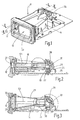
- the device module 11 there is an optical transmission path 12 for emitting an optical measurement signal, preferably laser pulses, and an optical reception path 13 for receiving the measurement signal reflected on an object.
- the device module 11 has an optics carrier 14, in which transmitting and receiving paths 12, 13 are separated from one another by correspondingly formed channels and chambers.
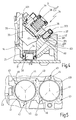
- Fig. 2 is the transmitting channel 18 and the transmitting chamber 19, which is aligned at right angles to the transmitting channel 18, and in Fig. 3 the receiving channel 20 and the receiving chamber 21 to see, which is also aligned at right angles to the receiving channel 20.
- the components of the optical transmission path 12 are an optical transmitter 22, which is designed as a collimator 24 with a collimator lens 26, a glass cover 27 terminating the transmission channel 18 at the front and a deflection mirror 28 arranged at the other end of the transmission channel 18, which can be adjusted on the optical carrier 14 is held. Via the deflection mirror 28, the optical axis 121 of the transmission path 12 can be adjusted.
- the components of the optical receiving path 13 are a receiver optics 29, here a receiving lens 20 frontally terminating receiver lens 32 with long focal length, placed at the other end of the receiving channel 20 deflecting mirror 33 which is adjustably held in the optics carrier 14, and a receiver 30, here a Light detector 31 with filter 34 (FIG. Fig. 4 ). Both the focal point on the light detector 31 and the direction of the optical axis 131 of the receiving path 13 can be changed and adjusted via the deflection mirror 33.
- the adjusting device 35 for the deflecting mirror 28 and the adjusting device 35 for the deflecting mirror 33 are the same, so that below with reference to the enlarged view in FIG Fig. 4 only the adjustment mirror 35 associated with the deflection mirror 33 in the reception path 13 will be described. This description applies equally to the adjusting device 35 of the deflecting mirror 28 arranged in the optical transmission path 12.
- the adjusting device 35 has a manufactured as a diecast mirror carrier 36 with Justierflansch 361, three alignment pins 37, a compression spring 38 and a spring clip 39, wherein the spring clip 39, as shown in Fig. 1 can be seen, the two adjusting devices 35 for deflecting mirror 28 and deflecting mirror 33 is common.
- a carrier profile 40 is formed with a flat profile surface 401.
- a circular recess 41 is introduced, in which the mirror support 36 is inserted so that the glued on the mirror support 36 deflection mirror 33 protrudes into the receiving channel 20.
- the Justierflansch 361 three in the circumferential direction of the mirror carrier 36 on a divider circuit 55 (FIG. Fig.
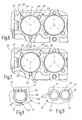
- the abutments 43 are arranged on a recess circle 41 concentric divider circle 44 with the same circle radius with the rotational angular distances of the alignment pins 37 corresponding rotational angle intervals to each other ( Fig. 5 ).
- the Abutments 43 are formed so that they on the one hand center the mirror support 36 via the alignment pins 37 in the recess 41 and on the other hand at least two abutments 43 allow a radial migration of the foot 371 of the respective alignment pin 37.
- a first abutment 43 as a blind hole 45 and the second abutment 43 designed as a radial longitudinal groove 46.
- This in Fig. 5 dotted indicated third abutment 43 is formed by the flat profile surface 401 of the support section 40.
- the diameter of the blind hole 45 and the groove width of the radial longitudinal groove 46 are dimensioned slightly larger than the outer diameter of the associated alignment pins 37 in the base 371.
- a centering of the mirror support 36 is secured concentrically to the receptacle 41.
- the longitudinal groove 46 allows the foot to migrate 371.
- Fig. 5 is still the adjacent recess 41 to see with equal abutments 43 for receiving the adjusting device 35 for the deflecting mirror 28 in the transmission path 12.
- the optical axis 131 of the receiving path 13 is adjusted so that a measuring signal incident in the optical axis 131 is deflected in the correct position onto the light detector 31 of the receiver 30.
- the distance of the deflection mirror 33 from the light detector 31 is adjusted so that the focal point of the receiver optics 29 comes to rest on the light detector 31.
- the three alignment pins 37 are more or less rotated in the threaded holes 42 in order to raise or lower the mirror support 36 and thus the deflection mirror 33 more or less relative to the carrier profile 40 and / or tilt.
- the threaded connection between the alignment pin 37 and mirror support 36 is executed without play. This can be effected by plastic coating of the adjusting pin 37 and / or the threaded bore 42.
- the thread of the alignment pins 37th be formed self-forming. The backlash can also be brought about by a spring element that generates a radial compressive force on the adjusting pin 37, or by other common measures.
- the radial compressive force is generated on all three alignment pins 37 by a prestressed, expanding snap ring 48, which can be inserted under elastic compression of its opposite ring ends within the pitch circle 55 between the three alignment pins 37. After releasing the snap ring 48 this applies with a radially outwardly directed pressure force to the three alignment pins 37.
- the snap ring 48 is provided with an anti-rotation 49, which is formed by an alignment pin 37 partially encompassing indentation 50.
- a clamping sleeve 51 which is slotted in a known manner in the axial direction, so that it is compressible by reducing the axial longitudinal slot 52 resiliently.
- the clamping sleeve 51 is inserted into a bore hole 53 made in the carrier profile 40.
- the axis of the borehole 53 has such a distance from the axis of the adjusting pin 36 screwed into the adjusting flange 361 that the clamping sleeve 51 radially presses against the adjusting pin 37 with prestressing.
- FIG. 6 and 7 are two embodiments of possible modifications of the abutment 43 in one of Fig. 5 corresponding plan view shown.
- Fig. 6 is an abutment 43 as a blind hole 45 and the other two abutment 43 as radial grooves 46 executed.
- all three abutments 43 are designed as radial longitudinal grooves 46.
- the diameter of the blind hole 45 and the width seen in the circumferential direction of the radial longitudinal grooves 46 each dimensioned slightly larger than the outer diameter the alignment pins 37 in the region of their immersion in the blind hole 45 and in the longitudinal groove 46. This in turn ensures the centering of the mirror support 36 concentric with the recess 41.
- the radial longitudinal grooves 46 allow a radial migration of the bases of the alignment pins 37, so that a distortion of the alignment pins 37 when adjusting the deflection mirror 33 is reliably prevented.
- the alignment pins 37 need not be designed as screwed in threaded holes threaded pins.
- threaded holes through holes can be provided in the Justierflansch of the mirror support 36 through which protrude the alignment pins.
- means must be provided which allow axial displacement of the alignment pins 37 relative to the mirror support 36, wherein the axial displacement of the alignment pins in each displacement position can be locked.
- the adjusting pins 37 may be dome-shaped or cone-shaped in their foot region which is supported on the abutments 43 and are supported on the preferably beveled edge region of the blind holes 45 or the bearing grooves 46. As a result, the alignment pins 37 center in the abutments 43 and lead in the same way a centering of the mirror support 36.
- Fig. 4 Such a design of adjusting pin 37 and abutment 43 (blind hole or radial longitudinal groove) is shown.
Description
Die Erfindung geht aus von einer Vorrichtung zum Justieren eines optischen Spiegels nach dem Oberbegriff des Anspruchs 1.The invention is based on a device for adjusting an optical mirror according to the preamble of claim 1.
Eine solche Justiervorrichtung wird beispielsweise in einem optischen Messgerät zur berührungslosen Abstandsmessung, insbesondere in einem als Handgerät konzipierten Laserentfernungsmesser, eingesetzt, wie es beispielsweise in der
Aus der
Aus der
Die erfindungsgemäße Justiervorrichtung mit den Merkmalen des Anspruchs 1 hat den Vorteil, dass durch die erfindungsgemäße Ausgestaltung der Widerlager am Trägerprofil eine exakte und schnelle Justierung des Spiegels auch bei Fertigungstoleranzen bezüglich der Lage und Ausrichtung der Durchgangslöcher im Spiegelträger und der in den Durchgangslöchern geführten Gewindestifte gewährleistet ist. In keiner Justierposition kann es infolge von Fehlertoleranzen zu einer Verspannung der Justiervorrichtung kommen, was eine langwierige und weniger exakte Justierung des Spiegels zur Folge hätte.The adjusting device according to the invention with the features of claim 1 has the advantage that the inventive design of the abutment on the support profile exact and quick adjustment of the mirror is guaranteed even with manufacturing tolerances with respect to the position and orientation of the through holes in the mirror support and guided in the through holes threaded pins , In no adjustment position can lead to a distortion of the adjusting device due to fault tolerances, which would have a lengthy and less accurate adjustment of the mirror result.
Durch die in den weiteren Ansprüchen aufgeführten Maßnahmen sind vorteilhafte Weiterbildungen und Verbesserungen der im Anspruch 1 angegebenen Justiervorrichtung möglich.The measures listed in the further claims advantageous refinements and improvements of claim 1 adjustment are possible.
Gemäß vorteilhafter Ausführungsformen der Erfindung sind die Widerlager in unterschiedlichen Kombinationen als Sackloch und radiale Längsnuten ausgebildet, wobei in einer Ausbildungskombination der Widerlager anstelle einer Längsnut auch eine ebene Fläche ohne Führungsfunktion für den Fußpunkt des Justierstiftes vorgesehen werden kann.According to advantageous embodiments of the invention, the abutments are formed in different combinations as a blind hole and radial grooves, wherein in a training combination of the abutment instead of a longitudinal groove and a flat surface without a guide function for the base of the adjusting pin can be provided.
Gemäß einer vorteilhaften Ausführungsform der Erfindung sind die Justierstifte als Gewindestifte und die Durchgangslöcher als Gewindebohrungen ausgebildet und Spielfreiheit in den Gewinden hergestellt. Die Spielfreiheit der Gewinde garantiert eine exakte Justierung des Spiegels bei extrem kleinen Stellwegen. Möglichkeiten zur Herstellung der Gewindespielfreiheit sind gemäß vorteilhafter Ausführungsformen der Erfindung: Kunststoffbeschichtung der Gewinde, selbstformende Gewinde und Federelemente, die die Gewindestifte mit radialer Druckkraft beaufschlagen.According to an advantageous embodiment of the invention, the adjusting pins are designed as threaded pins and the through holes as threaded holes and backlash produced in the threads. The freedom of movement of the threads guarantees an exact adjustment of the mirror with extremely small travel ranges. Possibilities for producing the thread clearance are according to advantageous embodiments of the invention: plastic coating of the thread, self-tapping thread and spring elements which act on the setscrews with radial compressive force.
Die Erfindung ist anhand von in der Zeichnung dargestellten Ausführungsbeispielen in der nachfolgenden Beschreibung näher erläutert. Es zeigen:
- Fig. 1
- eine perspektivische Unteransicht eines Gerätemoduls eines Entfernungsmessgeräts,
- Fig. 2
- einen Schnitt längs der Linie II - II in
Fig. 1 , - Fig. 3
- einen Schnitt längs der Linie III - III in
Fig. 1 , - Fig. 4
- eine vergrößerte Darstellung des Ausschnitts IV in
Fig. 3 , - Fig. 5
- eine Draufsicht in Richtung Pfeil V in
Fig. 4 bei entferntem Spiegelträger, - Fig. 6 und 7
- jeweils eine gleiche Darstellung wie in
Fig. 5 gemäß zweier modifizierter Ausführungsbeispiele, - Fig. 8
- eine Draufsicht eines Federelements zur Herstellung der Spielfreiheit dreier Gewindestifte in einer Justiervorrichtung gemäß
Fig. 4 , - Fig. 9
- eine Draufsicht eines Gewindestifts mit einem Federelement zur Herstellung der Spielfreiheit des Gewindestiftes.
- Fig. 1
- a perspective bottom view of a device module of a distance measuring device,
- Fig. 2
- a section along the line II - II in
Fig. 1 . - Fig. 3
- a section along the line III - III in
Fig. 1 . - Fig. 4
- an enlarged view of the section IV in
Fig. 3 . - Fig. 5
- a plan view in the direction of arrow V in
Fig. 4 with the mirror carrier removed, - 6 and 7
- each a same representation as in
Fig. 5 according to two modified embodiments, - Fig. 8
- a plan view of a spring element for producing the backlash of three setscrews in an adjusting device according to
Fig. 4 . - Fig. 9
- a top view of a threaded pin with a spring element for producing the backlash of the threaded pin.
Das in
Die Komponenten des optischen Sendepfads 12 sind ein optischer Sender 22, der als Kollimator 24 mit einer Kollimatorlinse 26 ausgebildet ist, eine den Sendekanal 18 frontseitig abschließende Abdeckscheibe 27 aus Glas und ein am anderen Ende des Sendekanals 18 angeordneter Umlenkspiegel 28, der justierbar am Optikträger 14 gehalten ist. Über den Umlenkspiegel 28 lässt sich die optische Achse 121 des Sendepfads 12 justieren.The components of the
Die Komponenten des optischen Empfangspfads 13 sind eine Empfängeroptik 29, hier eine den Empfangskanal 20 frontseitig abschließende Empfängerlinse 32 mit großer Brennweite, ein am anderen Ende des Empfangskanals 20 platzierter Umlenkspiegel 33, der justierbar im Optikträger 14 gehalten ist, und ein Empfänger 30, hier ein Lichtdetektor 31 mit Filter 34 (
Die Justierung des Umlenkspiegels 28 im Sendepfad 12 und des Umlenkspiegels 33 im Empfangspfad 13 erfolgt mittels einer jeweils dem Umlenkspiegel 28 bzw. 33 zugeordneten Justiervorrichtung 35. Die Justiervorrichtung 35 für den Umlenkspiegel 28 und die Justiervorrichtung 35 für den Umlenkspiegel 33 sind gleich ausgebildet, so dass nachfolgend anhand der vergrößerten Darstellung in
Die Justiervorrichtung 35 weist einen als Druckgussteil gefertigten Spiegelträger 36 mit Justierflansch 361, drei Justierstifte 37, eine Druckfeder 38 und einen Federbügel 39 auf, wobei der Federbügel 39, wie dies in
Im Ausführungsbeispiel gemäß
Mittels der Justiervorrichtung 35 wird die optische Achse 131 des Empfangspfads 13 so eingestellt, dass ein in der optischen Achse 131 einfallendes Messsignal lagerichtig auf den Lichtdetektor 31 des Empfänger 30 umgelenkt wird. Gleichzeitig wird auch der Abstand des Umlenkspiegels 33 von dem Lichtdetektor 31 eingestellt, damit der Brennpunkt der Empfängeroptik 29 auf dem Lichtdetektor 31 zu liegen kommt. Hierzu werden die drei Justierstifte 37 mehr oder weniger in den Gewindebohrungen 42 verdreht, um den Spiegelträger 36 und damit den Umlenkspiegel 33 mehr oder weniger gegenüber dem Trägerprofil 40 anzuheben oder abzusenken und/oder zu kippen.By means of the adjusting
Für eine exakte Justierung des Umlenkspiegels 33 ist die Gewindeverbindung zwischen Justierstift 37 und Spiegelträger 36 spielfrei ausgeführt. Dies kann durch Kunststoffbeschichtung des Justierstiftes 37 und/oder der Gewindebohrung 42 bewirkt werden. Zum gleichen Zweck kann das Gewinde der Justierstifte 37 selbstformend ausgebildet werden. Die Spielfreiheit kann aber auch durch ein Federelement herbeigeführt werden, das eine radial Druckkraft am Justierstift 37 erzeugt, oder durch andere geläufige Maßnahmen.For an exact adjustment of the
Mit dem Federelement 47 gemäß dem Ausführungsbeispiel der
In dem Ausführungsbeispiel der
In
Die Erfindung ist nicht auf die beschriebenen Ausführungsbeispiele der Justiervorrichtung 35 beschränkt. So müssen die Justierstifte 37 nicht als in Gewindelöchern verschraubbare Gewindestifte ausgeführt sein. Anstelle der Gewindebohrungen können Durchgangslöcher im Justierflansch des Spiegelträgers 36 vorgesehen werden, durch die die Justierstifte hindurchragen. In diesem Fall müssen Mittel vorgesehen werden, die eine axiale Verschiebung der Justierstifte 37 relativ zum Spiegelträger 36 ermöglichen, wobei die Axialverschiebung der Justierstifte in jeder Verschiebestellung arretierbar ist.The invention is not limited to the described embodiments of the adjusting
Die Justierstifte 37 können in ihrem auf den Widerlagern 43 sich abstützenden Fußbereich kalotten- oder kegelförmig ausgebildet sein und sich auf dem vorzugsweise abgeschrägten Randbereich der Sacklöcher 45 oder der Lagernuten 46 abstützen. Hierdurch zentrieren sich die Justierstifte 37 in den Widerlagern 43 und führen in gleicher Weise eine Zentrierung des Spiegelträgers 36 herbei. In
Claims (16)
- Device for adjusting an optical mirror (33), having a mirror carrier (36) which holds the mirror (33) and which is secured to a carrier profile (40), and having three adjusting pins (37) which pass through holes (42) which are arranged offset with respect to one another in the circumferential direction in the mirror carrier and which can be adjusted axially in relation to the mirror carrier (36), and are supported with their base points (371) on counter bearings (43) which are embodied on the carrier profile (40), characterized in that the counter bearings (43) are embodied in such a way that, on the one hand, the counter bearings (43) centre the mirror carrier (36) by means of the adjusting pins (37), and, on the other hand, at least two counter bearings (43) permit the base point (371) of the adjusting pins (37) to migrate radially by virtue of the fact that at least one counter bearing is embodied as a radially oriented longitudinal groove (46), wherein radially from the centre of a pitch snap ring (44) which surrounds the counter bearings (43) is defined in the direction of the respective counter bearing (43).
- Device according to Claim 1, characterized in that one counter bearing (43) is embodied as a blind hole (45), and one counter bearing (43) is embodied as a radially oriented longitudinal groove (46), and the third counter bearing (43) is formed by a planar surface (401).
- Device according to Claim 1, characterized in that one counter bearing (43) is embodied as a blind hole (45), and the two other counter bearings are each embodied as a radially oriented longitudinal groove (46).
- Device according to Claim 1, characterized in that all the counter bearings (43) are embodied as radially oriented longitudinal grooves (46).
- Device according to one of Claims 2-4, characterized in that the clear diameter of the blind hole (45) and/or the width of the radially oriented longitudinal groove (46) are dimensioned in such a way that the base point (371) of the adjusting pin (37) is held in the blind hold (45) or, respectively, in the radially oriented longitudinal groove (46) in the circumferential direction, in each case with a small amount of play.
- Device according to one of Claims 2-5, characterized in that the base areas of the adjusting pins (37) are dome-shaped or conical and rest on a preferably bevelled edge region of the blind holes (45) and/or of the radially oriented longitudinal grooves (46).
- Device according to one of Claims 1-6, characterized in that the adjusting pins (37) are embodied as threaded pins and the holes are embodied as threaded bores (42), and in that the threads engage one in the other without play.
- Device according to Claim 7, characterized in that the thread of the adjusting pins (37) and/or the thread of the threaded bores (42) is/are coated with plastic.
- Device according to Claim 7, characterized in that the thread of the adjusting pins (37) is of self-tapping design.
- Device according to Claim 7, characterized in that a radially compressive force is applied to the adjusting pins (37) by a spring element (47) which bears on all the adjusting pins (37).
- Device according to Claim 10, characterized in that the spring element (47) is a circlip (48) which spreads apart under prestress, fits within the pitch snap ring (55) which is described by the adjusting pins (37), and acts on the adjusting pins (37) with a radially outwardly directed compressive force.
- Device according to Claim 11, characterized in that the circlip (48) has an antitwist means (49).
- Device according to Claim 7, characterized in that a spring element (54) acts with a radially directed compressive force on each adjusting pin (37).
- Device according to Claim 13, characterized in that the spring element (54) is embodied as an axially slotted clamping sleeve (51) which is plugged into a receiving hole (53) which is made in the mirror carrier (36), and in that the receiving hole (53) is at such a radial distance from the threaded bore (42) that the clamping sleeve (51) presses radially against the adjusting pin (37).
- Device according to one of Claims 1-14, characterized by its use in an optical measuring device for contactless measurement of distances, preferably in a laser distance measuring device which is embodied as a handheld device.
- Measuring device for contactless measurement of distances, in particular a laser distance measuring device which is embodied as a handheld device, having an optical sending path (12) for emitting an optical measuring signal and an optical receiving path (13) for receiving the reflected measuring signal, and having at least one deflection mirror (28, 33) which is arranged in one of the optical paths (12, 13) and has the purpose of folding the optical axis (121, 131) of the optical path (12, 13), characterized by an adjusting device (35) which is assigned to the deflection mirror (28, 33), according to one of Claims 1-14.
Applications Claiming Priority (2)
| Application Number | Priority Date | Filing Date | Title |
|---|---|---|---|
| DE10314772A DE10314772A1 (en) | 2003-03-31 | 2003-03-31 | Device for adjusting an optical mirror |
| PCT/DE2003/004069 WO2004088356A1 (en) | 2003-03-31 | 2003-12-10 | Device for adjusting an optical mirror |
Publications (2)
| Publication Number | Publication Date |
|---|---|
| EP1651981A1 EP1651981A1 (en) | 2006-05-03 |
| EP1651981B1 true EP1651981B1 (en) | 2008-07-09 |
Family
ID=32980907
Family Applications (1)
| Application Number | Title | Priority Date | Filing Date |
|---|---|---|---|
| EP03816498A Expired - Lifetime EP1651981B1 (en) | 2003-03-31 | 2003-12-10 | Device for adjusting an optical mirror |
Country Status (5)
| Country | Link |
|---|---|
| US (1) | US20060152829A1 (en) |
| EP (1) | EP1651981B1 (en) |
| CN (1) | CN100406909C (en) |
| DE (2) | DE10314772A1 (en) |
| WO (1) | WO2004088356A1 (en) |
Families Citing this family (4)
| Publication number | Priority date | Publication date | Assignee | Title |
|---|---|---|---|---|
| DE102005041998B4 (en) | 2005-09-05 | 2018-11-29 | Robert Bosch Gmbh | Method for adjusting an imaging element and measuring device adjusted according to such a method |
| CN1952687B (en) * | 2006-11-02 | 2010-12-01 | 中国科学院安徽光学精密机械研究所 | Automatic collimating method and collimator set for light path of colidar |
| DE102011081382A1 (en) * | 2011-08-23 | 2013-02-28 | Robert Bosch Gmbh | Method and device for changing a light emission of at least one headlight of a vehicle |
| CN106501810A (en) * | 2015-09-08 | 2017-03-15 | 上海诺司纬光电仪器有限公司 | A kind of range-measurement system and the method for calibration range system light path |
Family Cites Families (47)
| Publication number | Priority date | Publication date | Assignee | Title |
|---|---|---|---|---|
| US2147156A (en) * | 1934-01-13 | 1939-02-14 | Radio Patents Corp | Photoelectric apparatus |
| US2129562A (en) * | 1938-02-17 | 1938-09-06 | Ilex Optical Company | Lens and diaphragm assembly |
| US3152527A (en) * | 1960-10-31 | 1964-10-13 | Jesse R Watson | Ballistics camera and mount |
| US3171322A (en) * | 1962-08-28 | 1965-03-02 | Kaplan Stanley | Anchor bolt |
| US3395628A (en) * | 1965-03-01 | 1968-08-06 | Sylvania Electric Prod | Exposure device |
| US3478608A (en) * | 1966-06-23 | 1969-11-18 | Electro Optics Associates | Aligning and mounting mechanism device |
| US3436050A (en) * | 1967-05-04 | 1969-04-01 | Dawson Inc Alexander | Adjustable mount for optical element |
| US3566101A (en) * | 1967-06-22 | 1971-02-23 | Leitz Ernst Gmbh | Centering device |
| US3866140A (en) * | 1968-11-22 | 1975-02-11 | Coherent Radiation Lab | Optical cavity for a laser |
| US3609014A (en) * | 1970-06-10 | 1971-09-28 | Kurz Arthur W Jun | Electric remote control rear view mirror |
| US3953113A (en) * | 1974-11-08 | 1976-04-27 | Liconix | Laser mirror mounting device |
| DE2702439C3 (en) * | 1977-01-19 | 1980-08-07 | Siemens Ag, 1000 Berlin Und 8000 Muenchen | Long focal length magnetic lens for corpuscular beam optical imaging of a large object |
| US4165921A (en) * | 1977-03-16 | 1979-08-28 | Jerry Kirsch | Horizontally and vertically adjustable mirror mounting |
| DE2714494C3 (en) * | 1977-03-31 | 1979-09-27 | Siemens Ag, 1000 Berlin Und 8000 Muenchen | Adjustment device for an optical element arranged in a carrier plate |
| DE2717299C2 (en) * | 1977-04-19 | 1982-11-25 | Siemens AG, 1000 Berlin und 8000 München | Device for receiving and driving a polygon mirror |
| DE3034922C2 (en) * | 1980-09-16 | 1982-11-25 | Siemens AG, 1000 Berlin und 8000 München | Adjustment and testing device for a laser distance measuring system |
| DD226172A3 (en) * | 1983-02-24 | 1985-08-14 | Halle Feinmech Werke Veb | ARRANGEMENT FOR STABILIZING THE OUTPUT PARAMETERS OF A FOLDED LASER RESONATOR |
| EP0166028A3 (en) * | 1984-06-25 | 1987-04-22 | Siemens Aktiengesellschaft | Adjustment device for a reflecting mirror of a laser resonator |
| JPS6136715A (en) * | 1984-07-30 | 1986-02-21 | Mitsubishi Electric Corp | Manipulator of multijoint reflection mirror system |
| DE3508306A1 (en) * | 1985-03-08 | 1986-09-11 | Fa. Carl Zeiss, 7920 Heidenheim | MICROSCOPE TUBE |
| US4678294A (en) * | 1985-12-03 | 1987-07-07 | Nostrand Willard R Van | Mirror assembly for determining distance to passed vehicle |
| US4891820A (en) * | 1985-12-19 | 1990-01-02 | Rofin-Sinar, Inc. | Fast axial flow laser circulating system |
| DE3719745A1 (en) * | 1987-06-12 | 1988-12-29 | Siemens Ag | GAS LASER WITH A HOUSING TUBE AND A CAPILLARY OUTSTANDING THIS |
| US4797736A (en) * | 1987-09-02 | 1989-01-10 | Luxtec Corporation | Head mounted illumination and camera assembly |
| DE4221079A1 (en) * | 1992-06-26 | 1994-01-05 | Licentia Gmbh | Height adjustable stand foot for domestic appts. - comprises foot plate with threaded shaft on which is screwed a foot nut |
| US5399227A (en) * | 1992-09-16 | 1995-03-21 | Abrams; Herbert M. | Composite eyeglass lens laminating holder |
| US5329347A (en) * | 1992-09-16 | 1994-07-12 | Varo Inc. | Multifunction coaxial objective system for a rangefinder |
| US5400184A (en) * | 1992-10-29 | 1995-03-21 | The United States Of America As Represented By The United States Department Of Energy | Kinematic high bandwidth mirror mount |
| JPH06250073A (en) * | 1993-02-26 | 1994-09-09 | Opt Mihara:Kk | Position adjusting and fitting mechanism for mirror |
| US5602622A (en) * | 1993-02-26 | 1997-02-11 | Ziegler; William R. | Alignable negative stage for a photographic enlarger |
| JPH0735856A (en) * | 1993-05-18 | 1995-02-07 | Opt:Kk | Optical range finder |
| JP3122830B2 (en) * | 1994-11-01 | 2001-01-09 | 株式会社小糸製作所 | Vehicle lighting |
| US5590149A (en) * | 1995-09-13 | 1996-12-31 | Spectra-Physics Lasers, Inc. | Mirror mount |
| JPH10170801A (en) * | 1996-12-12 | 1998-06-26 | Asahi Optical Co Ltd | Driving device for zoom lens barrel |
| DE19804051B4 (en) * | 1998-02-03 | 2004-10-28 | Robert Bosch Gmbh | distance measuring |
| US6582149B1 (en) * | 1998-12-15 | 2003-06-24 | Winfried K. W. Holscher | Coupling device for connecting a first workpiece to a second one |
| EP1176389A1 (en) * | 2000-07-24 | 2002-01-30 | Leica Geosystems AG | Method and device for optical range or speed measurement |
| DE50105852D1 (en) * | 2000-08-22 | 2005-05-12 | Continental Teves Ag & Co Ohg | DEVICE FOR DRIVING DYNAMIC CONTROL AND METHOD FOR ORIENTATION OF DRIVING DYNAMIC SENSORS |
| CN2478132Y (en) * | 2000-10-23 | 2002-02-20 | 中国科学院南京天文仪器研制中心 | Fixing regulator of optical reflector |
| US6554320B2 (en) * | 2000-11-01 | 2003-04-29 | Parker-Hannifin Corporation | Quick connect/disconnect coupling |
| JP2002244018A (en) * | 2001-02-16 | 2002-08-28 | Hitachi Electronics Eng Co Ltd | Mechanism for adjusting distance and angle of mirror |
| JP2002296476A (en) * | 2001-03-29 | 2002-10-09 | Olympus Optical Co Ltd | Lens frame |
| DE10117171B4 (en) * | 2001-04-06 | 2006-03-30 | Itw Automotive Products Gmbh & Co. Kg | Arrangement of a workpiece and a thread-forming screw |
| DE10130763A1 (en) * | 2001-06-26 | 2003-01-02 | Bosch Gmbh Robert | Device for optical distance measurement over a large measuring range |
| DE10157378B4 (en) * | 2001-11-22 | 2012-10-25 | Robert Bosch Gmbh | Measuring device for non-contact distance measurement |
| US7088506B2 (en) * | 2003-04-28 | 2006-08-08 | Leupold & Stevens, Inc. | Compact spotting scope with side focus control |
| DE102004048101B4 (en) * | 2004-09-30 | 2018-04-05 | Carl Zeiss Microscopy Gmbh | Adjustable microscope tube |
-
2003
- 2003-03-31 DE DE10314772A patent/DE10314772A1/en not_active Withdrawn
- 2003-12-10 EP EP03816498A patent/EP1651981B1/en not_active Expired - Lifetime
- 2003-12-10 CN CN2003801102322A patent/CN100406909C/en not_active Expired - Fee Related
- 2003-12-10 US US10/523,467 patent/US20060152829A1/en not_active Abandoned
- 2003-12-10 DE DE50310136T patent/DE50310136D1/de not_active Expired - Fee Related
- 2003-12-10 WO PCT/DE2003/004069 patent/WO2004088356A1/en active IP Right Grant
Also Published As
| Publication number | Publication date |
|---|---|
| DE10314772A1 (en) | 2004-10-14 |
| CN1761888A (en) | 2006-04-19 |
| DE50310136D1 (en) | 2008-08-21 |
| CN100406909C (en) | 2008-07-30 |
| US20060152829A1 (en) | 2006-07-13 |
| WO2004088356A1 (en) | 2004-10-14 |
| EP1651981A1 (en) | 2006-05-03 |
Similar Documents
| Publication | Publication Date | Title |
|---|---|---|
| DE3026908C2 (en) | Detachable connection for connecting optical fibers in pairs | |
| DE69233322T2 (en) | Device for optically connecting an optical element, for example an optical fiber, with a lens | |
| DE19724246B4 (en) | Adjustment device for a lens of a CCTV camera | |
| DE10026541A1 (en) | Device for the precise positioning of a component, in particular an optical component | |
| DE19502264C2 (en) | Module for an optical connection | |
| DE4139759A1 (en) | UP MILL | |
| DE10336104A1 (en) | Photoelectric sensor for use in automated production has a beam projector with a beam deflection angle adjuster comprising a pivoting plane parallel glass plate and a displaceable projection lens | |
| EP0992823B1 (en) | Method for aligning an electrooptical component | |
| DE2233639A1 (en) | HOLDER FOR OPTICAL COMPONENTS, IN PARTICULAR IN A LASER SYSTEM | |
| EP2473819A1 (en) | Device for optical distance measurement and method for adjusting such a device | |
| DE10048910A1 (en) | junction | |
| DE2656410C3 (en) | Device for adjusting an optical axis of an element, in particular a curved mirror | |
| EP1651981B1 (en) | Device for adjusting an optical mirror | |
| DE3613643C1 (en) | Fiber optic focusing device | |
| DE102005041998A1 (en) | Method for adjusting an imaging element and measuring device adjusted according to such a method | |
| DE102006000343B3 (en) | Optical assembly e.g. focused beam splitter, for e.g. opto-electronic measuring instrument, has lens carrier with partial carriers connected by connecting units that are fixed in openings in adjustable and frictionally-force fit manner | |
| EP2530351B1 (en) | Lens holder | |
| DE102007056642B3 (en) | Optical arrangement for optical sensor in image-processing system, has support fixable in hollow space of retainer in desired position, where displacement of displacement fin and cutting of thread structure takes place in bearing surface | |
| DE19700478C2 (en) | Fastening device | |
| DE4029075C1 (en) | ||
| DE10320991B4 (en) | Optical position measuring device | |
| EP0089671B1 (en) | Device for adjusting an optical component, e.g. an objective of an optical apparatus | |
| DD250784A1 (en) | OPTICAL ARRANGEMENT WITH RADIAL AND AXIAL TEMPERATURE COMPENSATION | |
| DE1961913A1 (en) | Fine adjustment device, in particular adjusting device for diaphragms arranged in the beam path of lasers | |
| DE102011012388B3 (en) | Adjuster for alignment of laser collimator utilized for emitting laser line or laser spot, has bars connected with sides of base part and carrier component such that twist of component is enabled |
Legal Events
| Date | Code | Title | Description |
|---|---|---|---|
| PUAI | Public reference made under article 153(3) epc to a published international application that has entered the european phase |
Free format text: ORIGINAL CODE: 0009012 |
|
| 17P | Request for examination filed |
Effective date: 20060224 |
|
| AK | Designated contracting states |
Kind code of ref document: A1 Designated state(s): DE FR |
|
| RBV | Designated contracting states (corrected) |
Designated state(s): DE FR |
|
| 17Q | First examination report despatched |
Effective date: 20061128 |
|
| GRAP | Despatch of communication of intention to grant a patent |
Free format text: ORIGINAL CODE: EPIDOSNIGR1 |
|
| GRAS | Grant fee paid |
Free format text: ORIGINAL CODE: EPIDOSNIGR3 |
|
| GRAA | (expected) grant |
Free format text: ORIGINAL CODE: 0009210 |
|
| AK | Designated contracting states |
Kind code of ref document: B1 Designated state(s): DE FR |
|
| REF | Corresponds to: |
Ref document number: 50310136 Country of ref document: DE Date of ref document: 20080821 Kind code of ref document: P |
|
| PLBE | No opposition filed within time limit |
Free format text: ORIGINAL CODE: 0009261 |
|
| STAA | Information on the status of an ep patent application or granted ep patent |
Free format text: STATUS: NO OPPOSITION FILED WITHIN TIME LIMIT |
|
| PGFP | Annual fee paid to national office [announced via postgrant information from national office to epo] |
Ref country code: DE Payment date: 20090224 Year of fee payment: 6 |
|
| 26N | No opposition filed |
Effective date: 20090414 |
|
| PGFP | Annual fee paid to national office [announced via postgrant information from national office to epo] |
Ref country code: FR Payment date: 20100105 Year of fee payment: 7 |
|
| PG25 | Lapsed in a contracting state [announced via postgrant information from national office to epo] |
Ref country code: DE Free format text: LAPSE BECAUSE OF NON-PAYMENT OF DUE FEES Effective date: 20100701 |
|
| REG | Reference to a national code |
Ref country code: FR Ref legal event code: ST Effective date: 20110831 |
|
| PG25 | Lapsed in a contracting state [announced via postgrant information from national office to epo] |
Ref country code: FR Free format text: LAPSE BECAUSE OF NON-PAYMENT OF DUE FEES Effective date: 20110103 |