EP1651981B1 - Dispositif pour regler un miroir optique - Google Patents
Dispositif pour regler un miroir optique Download PDFInfo
- Publication number
- EP1651981B1 EP1651981B1 EP03816498A EP03816498A EP1651981B1 EP 1651981 B1 EP1651981 B1 EP 1651981B1 EP 03816498 A EP03816498 A EP 03816498A EP 03816498 A EP03816498 A EP 03816498A EP 1651981 B1 EP1651981 B1 EP 1651981B1
- Authority
- EP
- European Patent Office
- Prior art keywords
- embodied
- adjusting
- mirror
- optical
- radially
- Prior art date
- Legal status (The legal status is an assumption and is not a legal conclusion. Google has not performed a legal analysis and makes no representation as to the accuracy of the status listed.)
- Expired - Lifetime
Links
- 230000003287 optical effect Effects 0.000 title claims description 36
- 238000005259 measurement Methods 0.000 claims description 8
- 238000013461 design Methods 0.000 claims description 3
- 238000010079 rubber tapping Methods 0.000 claims description 2
- 230000005540 biological transmission Effects 0.000 description 10
- 230000006835 compression Effects 0.000 description 3
- 238000007906 compression Methods 0.000 description 3
- 238000006073 displacement reaction Methods 0.000 description 3
- 230000008901 benefit Effects 0.000 description 2
- 230000005012 migration Effects 0.000 description 2
- 238000013508 migration Methods 0.000 description 2
- 239000006223 plastic coating Substances 0.000 description 2
- 239000011521 glass Substances 0.000 description 1
- 238000007654 immersion Methods 0.000 description 1
- 238000007373 indentation Methods 0.000 description 1
- 238000004519 manufacturing process Methods 0.000 description 1
- 230000007246 mechanism Effects 0.000 description 1
- 238000012986 modification Methods 0.000 description 1
- 230000004048 modification Effects 0.000 description 1
- 238000012549 training Methods 0.000 description 1
Images
Classifications
-
- G—PHYSICS
- G01—MEASURING; TESTING
- G01S—RADIO DIRECTION-FINDING; RADIO NAVIGATION; DETERMINING DISTANCE OR VELOCITY BY USE OF RADIO WAVES; LOCATING OR PRESENCE-DETECTING BY USE OF THE REFLECTION OR RERADIATION OF RADIO WAVES; ANALOGOUS ARRANGEMENTS USING OTHER WAVES
- G01S7/00—Details of systems according to groups G01S13/00, G01S15/00, G01S17/00
- G01S7/48—Details of systems according to groups G01S13/00, G01S15/00, G01S17/00 of systems according to group G01S17/00
- G01S7/481—Constructional features, e.g. arrangements of optical elements
- G01S7/4811—Constructional features, e.g. arrangements of optical elements common to transmitter and receiver
- G01S7/4813—Housing arrangements
-
- G—PHYSICS
- G01—MEASURING; TESTING
- G01S—RADIO DIRECTION-FINDING; RADIO NAVIGATION; DETERMINING DISTANCE OR VELOCITY BY USE OF RADIO WAVES; LOCATING OR PRESENCE-DETECTING BY USE OF THE REFLECTION OR RERADIATION OF RADIO WAVES; ANALOGOUS ARRANGEMENTS USING OTHER WAVES
- G01S17/00—Systems using the reflection or reradiation of electromagnetic waves other than radio waves, e.g. lidar systems
- G01S17/02—Systems using the reflection of electromagnetic waves other than radio waves
- G01S17/06—Systems determining position data of a target
- G01S17/08—Systems determining position data of a target for measuring distance only
-
- G—PHYSICS
- G01—MEASURING; TESTING
- G01S—RADIO DIRECTION-FINDING; RADIO NAVIGATION; DETERMINING DISTANCE OR VELOCITY BY USE OF RADIO WAVES; LOCATING OR PRESENCE-DETECTING BY USE OF THE REFLECTION OR RERADIATION OF RADIO WAVES; ANALOGOUS ARRANGEMENTS USING OTHER WAVES
- G01S7/00—Details of systems according to groups G01S13/00, G01S15/00, G01S17/00
- G01S7/48—Details of systems according to groups G01S13/00, G01S15/00, G01S17/00 of systems according to group G01S17/00
- G01S7/497—Means for monitoring or calibrating
- G01S7/4972—Alignment of sensor
-
- G—PHYSICS
- G02—OPTICS
- G02B—OPTICAL ELEMENTS, SYSTEMS OR APPARATUS
- G02B7/00—Mountings, adjusting means, or light-tight connections, for optical elements
- G02B7/18—Mountings, adjusting means, or light-tight connections, for optical elements for prisms; for mirrors
- G02B7/182—Mountings, adjusting means, or light-tight connections, for optical elements for prisms; for mirrors for mirrors
- G02B7/1822—Mountings, adjusting means, or light-tight connections, for optical elements for prisms; for mirrors for mirrors comprising means for aligning the optical axis
- G02B7/1824—Manual alignment
- G02B7/1825—Manual alignment made by screws, e.g. for laser mirrors
Definitions
- the invention is based on a device for adjusting an optical mirror according to the preamble of claim 1.
- Such an adjusting device is used for example in an optical measuring device for non-contact distance measurement, in particular in a designed as a hand-held laser rangefinder, as it is for example in the DE 198 04 051 A1 is described.
- a measuring device has an optical transmission path for emitting an optical measurement signal, for example laser pulses, and an optical reception path for receiving the reflected measurement signal.
- the optical axes of the transmitting and receiving paths are each folded by means of an optical mirror, which must be aligned accordingly when adjusting the measuring device.
- both the optical axis and the distance of the optical mirror must be set to an optical receiver.
- An adjusting device for an optical element in which the optical element, for example a reflector mirror of an optical resonator, is arranged in a support plate held on an abutment.
- the support plate is formed with corner regions which can be connected to one another by a triangle, on each of which, on both sides Support plate protruding adjustment screws are provided.
- the adjusting screws are adjusted by means of a radially acting, collet-like clamping play and stiff.
- the abutment of DE 27 14 494 A1 is formed with three bearings, wherein at each bearing a carrier plate embracing spring clip is mounted, which is rotatably mounted in the center axis of the adjusting screw and concentric with the free end to press the adjusting screw.
- a mechanism for adjusting the distance and angle of a mirror in which a conical groove and a V-shaped groove are formed on the movable mirror support plate.
- the conical groove receives the tip of one of the three adjustment screws of the mirror device, which are designed as micrometer screws on.
- the V-shaped groove takes in this mirror device on the tip of another adjustment screw.
- the adjusting device according to the invention with the features of claim 1 has the advantage that the inventive design of the abutment on the support profile exact and quick adjustment of the mirror is guaranteed even with manufacturing tolerances with respect to the position and orientation of the through holes in the mirror support and guided in the through holes threaded pins , In no adjustment position can lead to a distortion of the adjusting device due to fault tolerances, which would have a lengthy and less accurate adjustment of the mirror result.
- the abutments are formed in different combinations as a blind hole and radial grooves, wherein in a training combination of the abutment instead of a longitudinal groove and a flat surface without a guide function for the base of the adjusting pin can be provided.
- the adjusting pins are designed as threaded pins and the through holes as threaded holes and backlash produced in the threads.
- the freedom of movement of the threads guarantees an exact adjustment of the mirror with extremely small travel ranges.
- Possibilities for producing the thread clearance are according to advantageous embodiments of the invention: plastic coating of the thread, self-tapping thread and spring elements which act on the setscrews with radial compressive force.
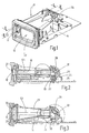
- a distance measuring device or laser rangefinder a measuring device for non-contact distance measurement
- the device module 11 there is an optical transmission path 12 for emitting an optical measurement signal, preferably laser pulses, and an optical reception path 13 for receiving the measurement signal reflected on an object.
- the device module 11 has an optics carrier 14, in which transmitting and receiving paths 12, 13 are separated from one another by correspondingly formed channels and chambers.
- Fig. 2 is the transmitting channel 18 and the transmitting chamber 19, which is aligned at right angles to the transmitting channel 18, and in Fig. 3 the receiving channel 20 and the receiving chamber 21 to see, which is also aligned at right angles to the receiving channel 20.
- the components of the optical transmission path 12 are an optical transmitter 22, which is designed as a collimator 24 with a collimator lens 26, a glass cover 27 terminating the transmission channel 18 at the front and a deflection mirror 28 arranged at the other end of the transmission channel 18, which can be adjusted on the optical carrier 14 is held. Via the deflection mirror 28, the optical axis 121 of the transmission path 12 can be adjusted.
- the components of the optical receiving path 13 are a receiver optics 29, here a receiving lens 20 frontally terminating receiver lens 32 with long focal length, placed at the other end of the receiving channel 20 deflecting mirror 33 which is adjustably held in the optics carrier 14, and a receiver 30, here a Light detector 31 with filter 34 (FIG. Fig. 4 ). Both the focal point on the light detector 31 and the direction of the optical axis 131 of the receiving path 13 can be changed and adjusted via the deflection mirror 33.
- the adjusting device 35 for the deflecting mirror 28 and the adjusting device 35 for the deflecting mirror 33 are the same, so that below with reference to the enlarged view in FIG Fig. 4 only the adjustment mirror 35 associated with the deflection mirror 33 in the reception path 13 will be described. This description applies equally to the adjusting device 35 of the deflecting mirror 28 arranged in the optical transmission path 12.
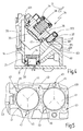
- the adjusting device 35 has a manufactured as a diecast mirror carrier 36 with Justierflansch 361, three alignment pins 37, a compression spring 38 and a spring clip 39, wherein the spring clip 39, as shown in Fig. 1 can be seen, the two adjusting devices 35 for deflecting mirror 28 and deflecting mirror 33 is common.
- a carrier profile 40 is formed with a flat profile surface 401.
- a circular recess 41 is introduced, in which the mirror support 36 is inserted so that the glued on the mirror support 36 deflection mirror 33 protrudes into the receiving channel 20.
- the Justierflansch 361 three in the circumferential direction of the mirror carrier 36 on a divider circuit 55 (FIG. Fig.
- the abutments 43 are arranged on a recess circle 41 concentric divider circle 44 with the same circle radius with the rotational angular distances of the alignment pins 37 corresponding rotational angle intervals to each other ( Fig. 5 ).
- the Abutments 43 are formed so that they on the one hand center the mirror support 36 via the alignment pins 37 in the recess 41 and on the other hand at least two abutments 43 allow a radial migration of the foot 371 of the respective alignment pin 37.
- a first abutment 43 as a blind hole 45 and the second abutment 43 designed as a radial longitudinal groove 46.
- This in Fig. 5 dotted indicated third abutment 43 is formed by the flat profile surface 401 of the support section 40.
- the diameter of the blind hole 45 and the groove width of the radial longitudinal groove 46 are dimensioned slightly larger than the outer diameter of the associated alignment pins 37 in the base 371.
- a centering of the mirror support 36 is secured concentrically to the receptacle 41.
- the longitudinal groove 46 allows the foot to migrate 371.
- Fig. 5 is still the adjacent recess 41 to see with equal abutments 43 for receiving the adjusting device 35 for the deflecting mirror 28 in the transmission path 12.
- the optical axis 131 of the receiving path 13 is adjusted so that a measuring signal incident in the optical axis 131 is deflected in the correct position onto the light detector 31 of the receiver 30.
- the distance of the deflection mirror 33 from the light detector 31 is adjusted so that the focal point of the receiver optics 29 comes to rest on the light detector 31.
- the three alignment pins 37 are more or less rotated in the threaded holes 42 in order to raise or lower the mirror support 36 and thus the deflection mirror 33 more or less relative to the carrier profile 40 and / or tilt.
- the threaded connection between the alignment pin 37 and mirror support 36 is executed without play. This can be effected by plastic coating of the adjusting pin 37 and / or the threaded bore 42.
- the thread of the alignment pins 37th be formed self-forming. The backlash can also be brought about by a spring element that generates a radial compressive force on the adjusting pin 37, or by other common measures.
- the radial compressive force is generated on all three alignment pins 37 by a prestressed, expanding snap ring 48, which can be inserted under elastic compression of its opposite ring ends within the pitch circle 55 between the three alignment pins 37. After releasing the snap ring 48 this applies with a radially outwardly directed pressure force to the three alignment pins 37.
- the snap ring 48 is provided with an anti-rotation 49, which is formed by an alignment pin 37 partially encompassing indentation 50.
- a clamping sleeve 51 which is slotted in a known manner in the axial direction, so that it is compressible by reducing the axial longitudinal slot 52 resiliently.
- the clamping sleeve 51 is inserted into a bore hole 53 made in the carrier profile 40.
- the axis of the borehole 53 has such a distance from the axis of the adjusting pin 36 screwed into the adjusting flange 361 that the clamping sleeve 51 radially presses against the adjusting pin 37 with prestressing.
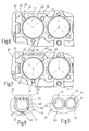
- FIG. 6 and 7 are two embodiments of possible modifications of the abutment 43 in one of Fig. 5 corresponding plan view shown.
- Fig. 6 is an abutment 43 as a blind hole 45 and the other two abutment 43 as radial grooves 46 executed.
- all three abutments 43 are designed as radial longitudinal grooves 46.
- the diameter of the blind hole 45 and the width seen in the circumferential direction of the radial longitudinal grooves 46 each dimensioned slightly larger than the outer diameter the alignment pins 37 in the region of their immersion in the blind hole 45 and in the longitudinal groove 46. This in turn ensures the centering of the mirror support 36 concentric with the recess 41.
- the radial longitudinal grooves 46 allow a radial migration of the bases of the alignment pins 37, so that a distortion of the alignment pins 37 when adjusting the deflection mirror 33 is reliably prevented.
- the alignment pins 37 need not be designed as screwed in threaded holes threaded pins.
- threaded holes through holes can be provided in the Justierflansch of the mirror support 36 through which protrude the alignment pins.
- means must be provided which allow axial displacement of the alignment pins 37 relative to the mirror support 36, wherein the axial displacement of the alignment pins in each displacement position can be locked.
- the adjusting pins 37 may be dome-shaped or cone-shaped in their foot region which is supported on the abutments 43 and are supported on the preferably beveled edge region of the blind holes 45 or the bearing grooves 46. As a result, the alignment pins 37 center in the abutments 43 and lead in the same way a centering of the mirror support 36.
- Fig. 4 Such a design of adjusting pin 37 and abutment 43 (blind hole or radial longitudinal groove) is shown.
Claims (16)
- Dispositif pour ajuster un miroir optique (33) comportant un support de miroir (36) recevant le miroir (33), ce support étant porté par un profil de support (40) ainsi que trois broches d'ajustage (37) traversant des orifices (42) prévus dans le support de miroir et décalés dans la direction périphérique, ces broches étant réglables axialement par rapport au support de miroir (36) et s'appuyant par des pieds (371) contre les appuis (43) réalisés sur le profil de support (40),
caractérisé en ce que
les appuis (43) sont réalisés pour que d'une part ils (43) assurent le centrage du support de miroir (36) par les broches d'ajustage (37) et que d'autre part au moins deux appuis (43) autorisent un déplacement radial du pied (371) des broches d'ajustage (37) en ce qu'au moins un appui est réalisé sous la forme d'une rainure longitudinale (46) alignée dans la direction radiale, l'expression radiale étant définie à partir du milieu d'un cercle diviseur (44) circonscrit à l'appui (43), dans la direction de l'appui (43) respectif. - Dispositif selon la revendication 1,
caractérisé en ce qu'
un appui (43) est réalisé comme perçage borgne (45) et un appui (43) est réalisé comme rainure longitudinale (46) alignée dans la direction radiale et le troisième appui (43) est formé par une surface plane (401). - Dispositif selon la revendication 1,
caractérisé en ce qu'
un appui (43) est réalisé comme perçage borgne (45) et les deux autres appuis sont réalisés chacun par une rainure longitudinale (46) alignée dans la direction radiale. - Dispositif selon la revendication 1,
caractérisé en ce que
tous les appuis (43) sont réalisés sous la forme de rainures longitudinales (46) alignées dans la direction radiale. - Dispositif selon l'une des revendications 2 à 4,
caractérisé en ce que
le diamètre libre du perçage borne (45) et/ou la largeur de la rainure longitudinale (46) alignée dans la direction radiale sont dimensionnés pour que le pied (371) de la broche d'ajustage (37) se loge dans le perçage borgne (45) ou dans la rainure longitudinale (46) alignée dans la direction radiale, suivant la direction périphérique chaque fois avec un faible jeu. - Dispositif selon l'une des revendications 2 à 5,
caractérisé en ce que
les zones des talons des broches d'ajustage (37) ont une forme de calotte ou de tronc de cône et s'appuient sur une surface de bord de préférence inclinée des perçages borgnes (45) et/ou des rainures longitudinales (46) alignées dans la direction radiale. - Dispositif selon l'une des revendications 1 à 6,
caractérisé en ce que
les broches d'ajustage (37) sont des broches filetées et les orifices traversants sont des taraudages (42) et en ce que les filetages se pénètrent sans jeu. - Dispositif selon la revendication 7,
caractérisé en ce que
le filetage des broches d'ajustage (37) et/ou le filetage des taraudages (42) est muni d'un revêtement en matière plastique. - Dispositif selon la revendication 7,
caractérisé en ce que
le filetage des broches d'ajustage (37) est auto-taraudeur. - Dispositif selon la revendication 7,
caractérisé en ce que
les broches d'ajustage (37) sont sollicitées par une poussée radiale appliquée par un élément de ressort (47) qui s'appuie contre toutes les broches d'ajustage (37). - Dispositif selon la revendication 10,
caractérisé en ce que
l'élément de ressort (47) est un anneau élastique (48) qui s'ouvre sous une précontrainte, cet anneau étant appliqué dans un cercle diviseur sous-tendu par les broches d'ajustage (37) et il agit sur chaque broche d'ajustage (37) avec une poussée dirigée radialement vers l'extérieur. - Dispositif selon la revendication 11,
caractérisé en ce que
l'anneau élastique (48) comporte un moyen de blocage en rotation (49). - Dispositif selon la revendication 7,
caractérisé par
un élément de ressort (54) exerçant une poussée dirigée radialement sur chaque broche d'ajustage (37). - Dispositif selon la revendication 13,
caractérisé en ce que
l'élément de ressort (54) est constitué par un manchon de serrage (51) fendu axialement, qui est engagé dans un orifice de réception (53) réalisé dans le support de miroir (36) et
l'orifice de réception (53) a une distance radiale par rapport au taraudage (42) pour que le manchon de serrage (51) soit pressé radialement contre la broche d'ajustage (37). - Dispositif selon l'une des revendications 1 à 14,
caractérisé par
son application à un appareil de mesure optique pour mesurer une distance sans contact, de préférence dans un télémètre laser réalisé sous forme d'appareil à main. - Appareil de mesure pour une mesure de distance sans contact, notamment comme télémètre laser réalisé sous forme d'appareil à main, comportant un chemin d'émission optique (12) pour émettre un signal de mesure optique et un chemin de réception optique (13) pour recevoir le signal de mesure réfléchi ainsi qu'au moins un miroir de renvoi (28, 33) installé dans l'un des chemins optiques (12, 13) pour renvoyer l'axe optique (121, 131) du chemin optique (12, 13),
caractérisé par
un dispositif d'ajustage (35) selon l'une des revendications 1 à 14 pour le miroir de renvoi (28, 33).
Applications Claiming Priority (2)
| Application Number | Priority Date | Filing Date | Title |
|---|---|---|---|
| DE10314772A DE10314772A1 (de) | 2003-03-31 | 2003-03-31 | Vorrichtung zum Justieren eines optischen Spiegels |
| PCT/DE2003/004069 WO2004088356A1 (fr) | 2003-03-31 | 2003-12-10 | Dispositif pour regler un miroir optique |
Publications (2)
| Publication Number | Publication Date |
|---|---|
| EP1651981A1 EP1651981A1 (fr) | 2006-05-03 |
| EP1651981B1 true EP1651981B1 (fr) | 2008-07-09 |
Family
ID=32980907
Family Applications (1)
| Application Number | Title | Priority Date | Filing Date |
|---|---|---|---|
| EP03816498A Expired - Lifetime EP1651981B1 (fr) | 2003-03-31 | 2003-12-10 | Dispositif pour regler un miroir optique |
Country Status (5)
| Country | Link |
|---|---|
| US (1) | US20060152829A1 (fr) |
| EP (1) | EP1651981B1 (fr) |
| CN (1) | CN100406909C (fr) |
| DE (2) | DE10314772A1 (fr) |
| WO (1) | WO2004088356A1 (fr) |
Families Citing this family (4)
| Publication number | Priority date | Publication date | Assignee | Title |
|---|---|---|---|---|
| DE102005041998B4 (de) | 2005-09-05 | 2018-11-29 | Robert Bosch Gmbh | Verfahren zur Justage eines abbildenden Elements sowie Messgerät justiert nach einem derartigen Verfahren |
| CN1952687B (zh) * | 2006-11-02 | 2010-12-01 | 中国科学院安徽光学精密机械研究所 | 激光雷达光路自动准直方法及准直仪 |
| DE102011081382A1 (de) * | 2011-08-23 | 2013-02-28 | Robert Bosch Gmbh | Verfahren und Vorrichtung zum Ändern einer Lichtaussendung zumindest eines Scheinwerfers eines Fahrzeugs |
| CN106501810A (zh) * | 2015-09-08 | 2017-03-15 | 上海诺司纬光电仪器有限公司 | 一种测距系统及校准测距系统光路的方法 |
Family Cites Families (47)
| Publication number | Priority date | Publication date | Assignee | Title |
|---|---|---|---|---|
| US2147156A (en) * | 1934-01-13 | 1939-02-14 | Radio Patents Corp | Photoelectric apparatus |
| US2129562A (en) * | 1938-02-17 | 1938-09-06 | Ilex Optical Company | Lens and diaphragm assembly |
| US3152527A (en) * | 1960-10-31 | 1964-10-13 | Jesse R Watson | Ballistics camera and mount |
| US3171322A (en) * | 1962-08-28 | 1965-03-02 | Kaplan Stanley | Anchor bolt |
| US3395628A (en) * | 1965-03-01 | 1968-08-06 | Sylvania Electric Prod | Exposure device |
| US3478608A (en) * | 1966-06-23 | 1969-11-18 | Electro Optics Associates | Aligning and mounting mechanism device |
| US3436050A (en) * | 1967-05-04 | 1969-04-01 | Dawson Inc Alexander | Adjustable mount for optical element |
| US3566101A (en) * | 1967-06-22 | 1971-02-23 | Leitz Ernst Gmbh | Centering device |
| US3866140A (en) * | 1968-11-22 | 1975-02-11 | Coherent Radiation Lab | Optical cavity for a laser |
| US3609014A (en) * | 1970-06-10 | 1971-09-28 | Kurz Arthur W Jun | Electric remote control rear view mirror |
| US3953113A (en) * | 1974-11-08 | 1976-04-27 | Liconix | Laser mirror mounting device |
| DE2702439C3 (de) * | 1977-01-19 | 1980-08-07 | Siemens Ag, 1000 Berlin Und 8000 Muenchen | Langbrennweitige magnetische Linse zur korpuskularstrahloptischen Abbildung eines großflächigen Objektes |
| US4165921A (en) * | 1977-03-16 | 1979-08-28 | Jerry Kirsch | Horizontally and vertically adjustable mirror mounting |
| DE2714494C3 (de) * | 1977-03-31 | 1979-09-27 | Siemens Ag, 1000 Berlin Und 8000 Muenchen | Justiervorrichtung für ein in einer Trägerplatte angeordnetes optisches Element |
| DE2717299C2 (de) * | 1977-04-19 | 1982-11-25 | Siemens AG, 1000 Berlin und 8000 München | Vorrichtung zur Aufnahme und zum Antrieb eines Polygonspiegels |
| DE3034922C2 (de) * | 1980-09-16 | 1982-11-25 | Siemens AG, 1000 Berlin und 8000 München | Justier- und Prüfeinrichtung für ein Laserentfernungsmeßsystem |
| DD226172A3 (de) * | 1983-02-24 | 1985-08-14 | Halle Feinmech Werke Veb | Anordnung zur stabilisierung der ausgangsparameter eines gefalteten laserresonators |
| EP0166028A3 (fr) * | 1984-06-25 | 1987-04-22 | Siemens Aktiengesellschaft | Dispositif de réglage pour un miroir réflecteur d'un résonateur laser |
| JPS6136715A (ja) * | 1984-07-30 | 1986-02-21 | Mitsubishi Electric Corp | 多関節反射鏡式マニピユレ−タ |
| DE3508306A1 (de) * | 1985-03-08 | 1986-09-11 | Fa. Carl Zeiss, 7920 Heidenheim | Mikroskoptubus |
| US4678294A (en) * | 1985-12-03 | 1987-07-07 | Nostrand Willard R Van | Mirror assembly for determining distance to passed vehicle |
| US4891820A (en) * | 1985-12-19 | 1990-01-02 | Rofin-Sinar, Inc. | Fast axial flow laser circulating system |
| DE3719745A1 (de) * | 1987-06-12 | 1988-12-29 | Siemens Ag | Gaslaser mit einem gehaeuserohr und einer ueber dieses hinausragenden kapillare |
| US4797736A (en) * | 1987-09-02 | 1989-01-10 | Luxtec Corporation | Head mounted illumination and camera assembly |
| DE4221079A1 (de) * | 1992-06-26 | 1994-01-05 | Licentia Gmbh | Höhenverstellbarer Standfuß für Haushaltsgeräte |
| US5329347A (en) * | 1992-09-16 | 1994-07-12 | Varo Inc. | Multifunction coaxial objective system for a rangefinder |
| US5399227A (en) * | 1992-09-16 | 1995-03-21 | Abrams; Herbert M. | Composite eyeglass lens laminating holder |
| US5400184A (en) * | 1992-10-29 | 1995-03-21 | The United States Of America As Represented By The United States Department Of Energy | Kinematic high bandwidth mirror mount |
| US5602622A (en) * | 1993-02-26 | 1997-02-11 | Ziegler; William R. | Alignable negative stage for a photographic enlarger |
| JPH06250073A (ja) * | 1993-02-26 | 1994-09-09 | Opt Mihara:Kk | ミラーの位置調節取付機構 |
| JPH0735856A (ja) * | 1993-05-18 | 1995-02-07 | Opt:Kk | 光波距離計 |
| JP3122830B2 (ja) * | 1994-11-01 | 2001-01-09 | 株式会社小糸製作所 | 車輌用灯具 |
| US5590149A (en) * | 1995-09-13 | 1996-12-31 | Spectra-Physics Lasers, Inc. | Mirror mount |
| JPH10170801A (ja) * | 1996-12-12 | 1998-06-26 | Asahi Optical Co Ltd | ズームレンズ鏡筒の駆動装置 |
| DE19804051B4 (de) * | 1998-02-03 | 2004-10-28 | Robert Bosch Gmbh | Entfernungsmeßgerät |
| DE59905514D1 (de) * | 1998-12-15 | 2003-06-12 | Winfried K W Holscher | Verbindungseinrichtung zum anschluss eines ersten werkstückes an ein zweites werkstück |
| EP1176389A1 (fr) * | 2000-07-24 | 2002-01-30 | Leica Geosystems AG | Méthode et dispositif de mesure optique de distance ou de vitesse |
| JP5745732B2 (ja) * | 2000-08-22 | 2015-07-08 | コンティネンタル・テーベス・アクチエンゲゼルシヤフト・ウント・コンパニー・オッフェネ・ハンデルスゲゼルシヤフト | ドライビングダイナミクスコントロールのための装置とドライビングダイナミクスセンサの位置決め方法 |
| CN2478132Y (zh) * | 2000-10-23 | 2002-02-20 | 中国科学院南京天文仪器研制中心 | 光学反射镜的固定调整装置 |
| US6554320B2 (en) * | 2000-11-01 | 2003-04-29 | Parker-Hannifin Corporation | Quick connect/disconnect coupling |
| JP2002244018A (ja) * | 2001-02-16 | 2002-08-28 | Hitachi Electronics Eng Co Ltd | ミラーの距離、角度調整機構 |
| JP2002296476A (ja) * | 2001-03-29 | 2002-10-09 | Olympus Optical Co Ltd | レンズ鏡枠 |
| DE10117171B4 (de) * | 2001-04-06 | 2006-03-30 | Itw Automotive Products Gmbh & Co. Kg | Anordnung aus einem Werkstück und einer gewindefurchenden Schraube |
| DE10130763A1 (de) * | 2001-06-26 | 2003-01-02 | Bosch Gmbh Robert | Vorrichtung zur optischen Distanzmessung über einen grossen Messbereich |
| DE10157378B4 (de) * | 2001-11-22 | 2012-10-25 | Robert Bosch Gmbh | Messgerät zur berührungslosen Abstandsmessung |
| US7088506B2 (en) * | 2003-04-28 | 2006-08-08 | Leupold & Stevens, Inc. | Compact spotting scope with side focus control |
| DE102004048101B4 (de) * | 2004-09-30 | 2018-04-05 | Carl Zeiss Microscopy Gmbh | Einstellbarer Mikroskoptubus |
-
2003
- 2003-03-31 DE DE10314772A patent/DE10314772A1/de not_active Withdrawn
- 2003-12-10 CN CN2003801102322A patent/CN100406909C/zh not_active Expired - Fee Related
- 2003-12-10 US US10/523,467 patent/US20060152829A1/en not_active Abandoned
- 2003-12-10 DE DE50310136T patent/DE50310136D1/de not_active Expired - Fee Related
- 2003-12-10 EP EP03816498A patent/EP1651981B1/fr not_active Expired - Lifetime
- 2003-12-10 WO PCT/DE2003/004069 patent/WO2004088356A1/fr active IP Right Grant
Also Published As
| Publication number | Publication date |
|---|---|
| CN1761888A (zh) | 2006-04-19 |
| US20060152829A1 (en) | 2006-07-13 |
| EP1651981A1 (fr) | 2006-05-03 |
| DE50310136D1 (fr) | 2008-08-21 |
| CN100406909C (zh) | 2008-07-30 |
| DE10314772A1 (de) | 2004-10-14 |
| WO2004088356A1 (fr) | 2004-10-14 |
Similar Documents
| Publication | Publication Date | Title |
|---|---|---|
| DE3026908C2 (de) | Lösbare Verbindung zum paarweisen Verbinden von Lichtleitfasern | |
| EP0546376B1 (fr) | Fraiseuse portative | |
| DE69233322T2 (de) | Vorrichtung zum optischen Verbinden eines optischen Elements, zum Beispiel einer optischen Faser, mit einer Linse | |
| DE19724246B4 (de) | Einstellvorrichtung für ein Objektiv einer CCTV-Kamera | |
| DE10026541A1 (de) | Vorrichtung zur präzisen Positionierung eines Bauteils, insbesondere eines optischen Bauteiles | |
| DE19502264C2 (de) | Modul für eine optische Verbindung | |
| DE10336104A1 (de) | Photoelektrischer Sensor | |
| EP0992823B1 (fr) | Procédé de réglage d'un élément électrooptique | |
| DE2233639A1 (de) | Halterung fuer optische bauelemente, insbesondere in einem lasersystem | |
| EP2473819A1 (fr) | Dispositif de mesure optique de distance, et procédé de réglage d'un tel dispositif | |
| DE10048910A1 (de) | Verbindungsstelle | |
| DE2656410B2 (de) | Vorrichtung zum Verstellen einer optischen Achse eines Elementes, insbesondere eines gekrümmten Spiegels | |
| EP1651981B1 (fr) | Dispositif pour regler un miroir optique | |
| DE3613643C1 (de) | Faseroptische Fokusiereinrichtung | |
| DE102005041998A1 (de) | Verfahren zur Justage eines abbildenden Elements sowie Messgerät justiert nach einem derartigen Verfahren | |
| DE102006000343B3 (de) | Justierbare optische Baugruppe | |
| EP2530351B1 (fr) | Support optique | |
| DE102007056642B3 (de) | Optikanordnung | |
| DE19700478C2 (de) | Befestigungsvorrichtung | |
| DE4029075C1 (fr) | ||
| DE10320991B4 (de) | Optische Positionsmesseinrichtung | |
| EP0089671B1 (fr) | Dispositif d'ajustage d'un élément optique p.ex. d'un objectif d'un appareil optique | |
| DD250784A1 (de) | Optische anordnung mit radialer und axialer temperaturkompensation | |
| DE1961913A1 (de) | Feineinstellvorrichtung,insbesondere Justiervorrichtung fuer im Strahlengang von Lasern angeordneten Blenden | |
| DE102011012388B3 (de) | Justiervorrichtung |
Legal Events
| Date | Code | Title | Description |
|---|---|---|---|
| PUAI | Public reference made under article 153(3) epc to a published international application that has entered the european phase |
Free format text: ORIGINAL CODE: 0009012 |
|
| 17P | Request for examination filed |
Effective date: 20060224 |
|
| AK | Designated contracting states |
Kind code of ref document: A1 Designated state(s): DE FR |
|
| RBV | Designated contracting states (corrected) |
Designated state(s): DE FR |
|
| 17Q | First examination report despatched |
Effective date: 20061128 |
|
| GRAP | Despatch of communication of intention to grant a patent |
Free format text: ORIGINAL CODE: EPIDOSNIGR1 |
|
| GRAS | Grant fee paid |
Free format text: ORIGINAL CODE: EPIDOSNIGR3 |
|
| GRAA | (expected) grant |
Free format text: ORIGINAL CODE: 0009210 |
|
| AK | Designated contracting states |
Kind code of ref document: B1 Designated state(s): DE FR |
|
| REF | Corresponds to: |
Ref document number: 50310136 Country of ref document: DE Date of ref document: 20080821 Kind code of ref document: P |
|
| PLBE | No opposition filed within time limit |
Free format text: ORIGINAL CODE: 0009261 |
|
| STAA | Information on the status of an ep patent application or granted ep patent |
Free format text: STATUS: NO OPPOSITION FILED WITHIN TIME LIMIT |
|
| PGFP | Annual fee paid to national office [announced via postgrant information from national office to epo] |
Ref country code: DE Payment date: 20090224 Year of fee payment: 6 |
|
| 26N | No opposition filed |
Effective date: 20090414 |
|
| PGFP | Annual fee paid to national office [announced via postgrant information from national office to epo] |
Ref country code: FR Payment date: 20100105 Year of fee payment: 7 |
|
| PG25 | Lapsed in a contracting state [announced via postgrant information from national office to epo] |
Ref country code: DE Free format text: LAPSE BECAUSE OF NON-PAYMENT OF DUE FEES Effective date: 20100701 |
|
| REG | Reference to a national code |
Ref country code: FR Ref legal event code: ST Effective date: 20110831 |
|
| PG25 | Lapsed in a contracting state [announced via postgrant information from national office to epo] |
Ref country code: FR Free format text: LAPSE BECAUSE OF NON-PAYMENT OF DUE FEES Effective date: 20110103 |