EP2530320A1 - Compressor and refrigeration device - Google Patents
Compressor and refrigeration device Download PDFInfo
- Publication number
- EP2530320A1 EP2530320A1 EP11737096A EP11737096A EP2530320A1 EP 2530320 A1 EP2530320 A1 EP 2530320A1 EP 11737096 A EP11737096 A EP 11737096A EP 11737096 A EP11737096 A EP 11737096A EP 2530320 A1 EP2530320 A1 EP 2530320A1
- Authority
- EP
- European Patent Office
- Prior art keywords
- oil
- refrigerant
- flow path
- casing
- compressor
- Prior art date
- Legal status (The legal status is an assumption and is not a legal conclusion. Google has not performed a legal analysis and makes no representation as to the accuracy of the status listed.)
- Granted
Links
- 238000005057 refrigeration Methods 0.000 title description 14
- 239000003921 oil Substances 0.000 claims abstract description 199
- 239000003507 refrigerant Substances 0.000 claims abstract description 134
- 230000007246 mechanism Effects 0.000 claims abstract description 108
- 239000010687 lubricating oil Substances 0.000 claims abstract description 100
- 230000006835 compression Effects 0.000 claims abstract description 66
- 238000007906 compression Methods 0.000 claims abstract description 66
- 238000000926 separation method Methods 0.000 claims description 26
- 230000007423 decrease Effects 0.000 abstract description 13
- 238000000034 method Methods 0.000 abstract description 8
- 230000008569 process Effects 0.000 abstract description 8
- 230000002093 peripheral effect Effects 0.000 description 11
- 230000000149 penetrating effect Effects 0.000 description 9
- 230000000694 effects Effects 0.000 description 6
- 230000009471 action Effects 0.000 description 5
- 230000009467 reduction Effects 0.000 description 5
- 239000000470 constituent Substances 0.000 description 4
- 230000008878 coupling Effects 0.000 description 4
- 238000010168 coupling process Methods 0.000 description 4
- 238000005859 coupling reaction Methods 0.000 description 4
- 238000004891 communication Methods 0.000 description 3
- 230000004048 modification Effects 0.000 description 3
- 238000012986 modification Methods 0.000 description 3
- 238000005119 centrifugation Methods 0.000 description 2
- 238000012546 transfer Methods 0.000 description 2
- RYGMFSIKBFXOCR-UHFFFAOYSA-N Copper Chemical compound [Cu] RYGMFSIKBFXOCR-UHFFFAOYSA-N 0.000 description 1
- 229910001111 Fine metal Inorganic materials 0.000 description 1
- 230000001174 ascending effect Effects 0.000 description 1
- 230000008859 change Effects 0.000 description 1
- 238000001816 cooling Methods 0.000 description 1
- 230000006735 deficit Effects 0.000 description 1
- 238000007599 discharging Methods 0.000 description 1
- 238000010438 heat treatment Methods 0.000 description 1
- -1 is increased Substances 0.000 description 1
- 230000001050 lubricating effect Effects 0.000 description 1
- 238000005461 lubrication Methods 0.000 description 1
- 238000012856 packing Methods 0.000 description 1
- 238000009987 spinning Methods 0.000 description 1
Images


Classifications
-
- F—MECHANICAL ENGINEERING; LIGHTING; HEATING; WEAPONS; BLASTING
- F04—POSITIVE - DISPLACEMENT MACHINES FOR LIQUIDS; PUMPS FOR LIQUIDS OR ELASTIC FLUIDS
- F04B—POSITIVE-DISPLACEMENT MACHINES FOR LIQUIDS; PUMPS
- F04B39/00—Component parts, details, or accessories, of pumps or pumping systems specially adapted for elastic fluids, not otherwise provided for in, or of interest apart from, groups F04B25/00 - F04B37/00
- F04B39/02—Lubrication
-
- F—MECHANICAL ENGINEERING; LIGHTING; HEATING; WEAPONS; BLASTING
- F04—POSITIVE - DISPLACEMENT MACHINES FOR LIQUIDS; PUMPS FOR LIQUIDS OR ELASTIC FLUIDS
- F04C—ROTARY-PISTON, OR OSCILLATING-PISTON, POSITIVE-DISPLACEMENT MACHINES FOR LIQUIDS; ROTARY-PISTON, OR OSCILLATING-PISTON, POSITIVE-DISPLACEMENT PUMPS
- F04C18/00—Rotary-piston pumps specially adapted for elastic fluids
- F04C18/02—Rotary-piston pumps specially adapted for elastic fluids of arcuate-engagement type, i.e. with circular translatory movement of co-operating members, each member having the same number of teeth or tooth-equivalents
- F04C18/0207—Rotary-piston pumps specially adapted for elastic fluids of arcuate-engagement type, i.e. with circular translatory movement of co-operating members, each member having the same number of teeth or tooth-equivalents both members having co-operating elements in spiral form
- F04C18/0215—Rotary-piston pumps specially adapted for elastic fluids of arcuate-engagement type, i.e. with circular translatory movement of co-operating members, each member having the same number of teeth or tooth-equivalents both members having co-operating elements in spiral form where only one member is moving
-
- F—MECHANICAL ENGINEERING; LIGHTING; HEATING; WEAPONS; BLASTING
- F04—POSITIVE - DISPLACEMENT MACHINES FOR LIQUIDS; PUMPS FOR LIQUIDS OR ELASTIC FLUIDS
- F04B—POSITIVE-DISPLACEMENT MACHINES FOR LIQUIDS; PUMPS
- F04B39/00—Component parts, details, or accessories, of pumps or pumping systems specially adapted for elastic fluids, not otherwise provided for in, or of interest apart from, groups F04B25/00 - F04B37/00
- F04B39/02—Lubrication
- F04B39/0223—Lubrication characterised by the compressor type
- F04B39/023—Hermetic compressors
-
- F—MECHANICAL ENGINEERING; LIGHTING; HEATING; WEAPONS; BLASTING
- F04—POSITIVE - DISPLACEMENT MACHINES FOR LIQUIDS; PUMPS FOR LIQUIDS OR ELASTIC FLUIDS
- F04B—POSITIVE-DISPLACEMENT MACHINES FOR LIQUIDS; PUMPS
- F04B39/00—Component parts, details, or accessories, of pumps or pumping systems specially adapted for elastic fluids, not otherwise provided for in, or of interest apart from, groups F04B25/00 - F04B37/00
- F04B39/04—Measures to avoid lubricant contaminating the pumped fluid
-
- F—MECHANICAL ENGINEERING; LIGHTING; HEATING; WEAPONS; BLASTING
- F04—POSITIVE - DISPLACEMENT MACHINES FOR LIQUIDS; PUMPS FOR LIQUIDS OR ELASTIC FLUIDS
- F04C—ROTARY-PISTON, OR OSCILLATING-PISTON, POSITIVE-DISPLACEMENT MACHINES FOR LIQUIDS; ROTARY-PISTON, OR OSCILLATING-PISTON, POSITIVE-DISPLACEMENT PUMPS
- F04C23/00—Combinations of two or more pumps, each being of rotary-piston or oscillating-piston type, specially adapted for elastic fluids; Pumping installations specially adapted for elastic fluids; Multi-stage pumps specially adapted for elastic fluids
- F04C23/008—Hermetic pumps
-
- F—MECHANICAL ENGINEERING; LIGHTING; HEATING; WEAPONS; BLASTING
- F04—POSITIVE - DISPLACEMENT MACHINES FOR LIQUIDS; PUMPS FOR LIQUIDS OR ELASTIC FLUIDS
- F04C—ROTARY-PISTON, OR OSCILLATING-PISTON, POSITIVE-DISPLACEMENT MACHINES FOR LIQUIDS; ROTARY-PISTON, OR OSCILLATING-PISTON, POSITIVE-DISPLACEMENT PUMPS
- F04C29/00—Component parts, details or accessories of pumps or pumping installations, not provided for in groups F04C18/00 - F04C28/00
- F04C29/02—Lubrication; Lubricant separation
- F04C29/026—Lubricant separation
-
- F—MECHANICAL ENGINEERING; LIGHTING; HEATING; WEAPONS; BLASTING
- F04—POSITIVE - DISPLACEMENT MACHINES FOR LIQUIDS; PUMPS FOR LIQUIDS OR ELASTIC FLUIDS
- F04C—ROTARY-PISTON, OR OSCILLATING-PISTON, POSITIVE-DISPLACEMENT MACHINES FOR LIQUIDS; ROTARY-PISTON, OR OSCILLATING-PISTON, POSITIVE-DISPLACEMENT PUMPS
- F04C29/00—Component parts, details or accessories of pumps or pumping installations, not provided for in groups F04C18/00 - F04C28/00
- F04C29/02—Lubrication; Lubricant separation
- F04C29/028—Means for improving or restricting lubricant flow
-
- F—MECHANICAL ENGINEERING; LIGHTING; HEATING; WEAPONS; BLASTING
- F04—POSITIVE - DISPLACEMENT MACHINES FOR LIQUIDS; PUMPS FOR LIQUIDS OR ELASTIC FLUIDS
- F04C—ROTARY-PISTON, OR OSCILLATING-PISTON, POSITIVE-DISPLACEMENT MACHINES FOR LIQUIDS; ROTARY-PISTON, OR OSCILLATING-PISTON, POSITIVE-DISPLACEMENT PUMPS
- F04C29/00—Component parts, details or accessories of pumps or pumping installations, not provided for in groups F04C18/00 - F04C28/00
- F04C29/12—Arrangements for admission or discharge of the working fluid, e.g. constructional features of the inlet or outlet
Definitions
- the present invention relates to a compressor and to a refrigeration device; more particularly, the present invention relates to a compressor provided with a mechanism for returning, to the compressor, lubricating oil included in refrigerant discharged from the compressor, as well as to a refrigeration device provided with the compressor.
- lubricating oil (refrigerator oil) is used in order to enhance the lubricating performance of a sliding part of a compression mechanism in the interior of the compressor. For this reason, the lubricating oil is included in refrigerant discharged from the compressor.
- Patent Literature 1 Japanese Unexamined Publication No. 5-223074 recites a scroll-type compressor which is connected to an oil separator for separating out lubricating oil from refrigerant discharged from the compressor.
- a discharge tube installed on an upper surface of a casing of this scroll compressor is in direct communication with the oil separator, which is installed on the exterior of the compressor.
- Refrigerant discharged from the discharge tube is sent to the interior of the oil separator and passes through oil separating means in which a fine metal wire is formed in a roll, the lubricating oil being thus separated.
- the lubricating oil separated out from the refrigerant is stored in an oil reservoir chamber in the interior of the oil separator.
- This oil reservoir chamber communicates with a space at an upper part of the oil reservoir chamber in the interior of the compressor, via an oil return flow path, which has resistance. As such, the lubricating oil stored in the oil reservoir chamber in the interior of the oil separator is returned to the oil reservoir chamber in the interior of the compressor, via the oil return flow path.
- An objective of the present invention is to provide a compressor whereby any decline in volumetric efficiency can be suppressed in a process for returning, to the interior of the compressor, high-temperature lubricating oil having been separated out by an oil separator.
- a compressor according to a first aspect of the present invention is provided with a casing, a compression mechanism, an oil separator, and an oil return passage.
- the casing stores lubricating oil in a bottom part.
- the compression mechanism is accommodated in the interior of the casing.
- the oil separator is installed on the exterior of the casing. The oil separator separates out lubricating oil fro high-pressure refrigerant discharged from the compression mechanism.
- the lubricating oil separated out by the oil separator flows through the oil return, passage.
- the oil return passage communicates with a high-pressure space formed in the interior of the casing. The high-pressure refrigerant flows into the high-pressure space.
- the lubricating oil is separated out by the oil separator from the refrigerant compressed by the compression mechanism, and the separated-out lubricating oil is returned directly to the high-pressure space in the interior of the casing by way of the oil return passage.
- This high-pressure space is a space where refrigerant compressed by the compression mechanism is discharged.
- the lubricating oil separated out by the oil separator will not be returned to a low-pressure space filled with as-yet uncompressed refrigerant, and therefore the as-yet uncompressed refrigerant will not be heated and expanded by the high-temperature lubricating oil. This makes it possible for any decline in volumetric efficiency to be suppressed in the compressor according to the first aspect.
- the compressor according to the first aspect there is little difference in pressure between the high-pressure space and the oil return passage, through which the lubricating oil separated out by the oil separator flows. As such, there is no longer a need for a capillary tubing or other pressure adjustment mechanism, which has been necessary in a conventional compression mechanism in order to return only a suitable amount of lubricating oil to the low-pressure space filled with as-yet uncompressed refrigerant. This makes it possible to achieve a cost reduction based on a reduced number of components in the compressor according to the first aspect.
- a compressor according to a second aspect of the present invention is the compressor according to the first aspect, further provided with an ejector mechanism formed in the high-pressure space.
- the ejector mechanism has a refrigerant-accelerating flow path and an oil suction flow path.
- the high-pressure refrigerant flows in the refrigerant-accelerating flow path via a narrowed part, whereby a flow rate of the high-pressure refrigerant is increased.
- the oil suction flow path communicates with the oil return passage, the lubricating oil being sucked from the oil return passage into the oil suction flow path.
- the oil suction flow path merges with the refrigerant-accelerating flow path.
- the flow rate of the refrigerant passing through the narrowed part of the refrigerant-accelerating flow path of the ejector mechanism is increased, and a negative pressure is generated due to an ejector effect in the oil suction flow path merging with the refrigerant-accelerating flow path, wherefore the lubricating oil is sucked in to the oil suction flow path from the oil return passage, and the sucked-in lubricating oil is supplied to the refrigerant-accelerating flow path.
- a compressor according to a third aspect of the present invention is the compressor according to the second aspect, wherein the oil suction flow path merges with the refrigerant-accelerating flow path in a substantially parallel manner.
- the compressor according to the third aspect because the oil suction flow path merges with the refrigerant-accelerating flow path in a substantially parallel manner, the flow of lubricating oil in the oil suction flow path more readily merges into the refrigerant-accelerating flow path. For this reason, the lubricating oil sucked in to the oil suction flow path from the oil return passage is supplied more efficiently to the refrigerant-accelerating flow path. This makes it possible to further increase the amount of the lubricating oil returned to the interior of the compressor in the compressor according to the third aspect.
- a compressor according to a fourth aspect of the present invention is the compressor according to the second aspect or the third aspect, wherein the refrigerant-accelerating flow path is formed from a first flow-path-forming member and a second flow-path-forming member.
- the oil suction flow path is formed from the casing and the second flow-path-forming member.
- the second flow-path-forming member is installed in the interior of a space (hereinbelow called a first space) surrounded by the first flow-path-forming member and the casing, thus forming the refrigerant-accelerating flow path and the oil suction flow path having the narrowed part.
- the first flow-path-forming member functions as a so-called gas guide member, and the refrigerant compressed by the compression mechanism is able to pass through the first space.
- the second flow-path-forming member functions as a so-called constricted-flow plate, and is installed such that a part of a flow path for the refrigerant in the first space is gradually narrowed.
- the second flow-path-forming member together with the first flow-path-forming member, forms a part of the refrigerant-accelerating flow path having the narrowed part.
- a space hereinbelow called a second space
- This second communicates with the first space at a point where the refrigerant has passed through the narrowed part, and is also the oil suction flow path communicating with the oil return passage.
- a compressor according to a fifth aspect of the present invention is the compressor according to the second aspect or the third aspect, further provided with a main for supporting the compression mechanism.
- the main frame has a through-hole.
- the through-hole communicates with the high-pressure space, and is a space through which the high-pressure refrigerant discharged from the compression mechanism flows.
- the refrigerant-accelerating flow path includes the through-hole having the narrowed part as well as a space formed from the casing and the main frame.
- the oil suction flow path includes a space formed from the casing and the main frame.
- the narrowed part is formed in the through-hole of the main frame. It is possible to mechanically process the main frame and thereby to provide a narrowed part having a high degree of shape accuracy. This makes it possible to curb any variance in the suction force imparted by the ejector mechanism in the compressor according to the fifth aspect.
- a compressor according to a sixth aspect of the present invention is provided with a casing, a compression mechanism, a main frame, and an ejector mechanism.
- the casing stores lubricating oil in a bottom part.
- the compression mechanism is accommodated in the interior of the casing.
- the compression mechanism compresses refrigerant and discharges high-pressure refrigerant.
- the main frame supports the compression mechanism.
- the ejector mechanism is accommodated in the interior of the casing.
- the casing has, in the interior thereof, a high-pressure space and an oil separation space.
- the high-pressure space is a space into which the high-pressure refrigerant discharged from the compression mechanism flows.
- the oil separation space is a different space than the high-pressure space, and is a space where lubricating oil is separated out from the high-pressure refrigerant
- the main frame has a through-hole and an oil release hole.
- the through-hole communicates with the high-pressure space, and is a space through which the high-pressure refrigerant discharged from the compression mechanism flows.
- the oil release hole communicates with the high-pressure space, and is a space where the lubricating oil separated out in the oil separation space flows.
- the ejector mechanism has a refrigerant-accelerating flow path, where the high-pressure refrigerant flows via a narrowed part whereby the flow rate of the high-pressure refrigerant, is increased, and an oil suction flow path, which merges with the refrigerant-accelerating flow path.
- the refrigerant-accelerating flow path includes a through-hole having a narrowed part as well as a space formed from the casing and the main frame.
- the oil suction flow path includes an oil release hole.
- the lubricating oil separated out in the oil separation space inside the casing will not be stored in the bottom part of the oil separation space, but rather will be rapidly released into the high-pressure space by the ejector mechanism. This makes it possible to curb any decline in the efficiency at which the lubricating oil is separated out in the compressor according to the sixth aspect.
- a refrigeration device is provided with the compressor according to any of the first through sixth aspects, a condenser, an expansion mechanism, and an evaporator.
- a refrigeration device can be provided with the compressor according to any of the first through sixth aspects. This makes it possible to suppress any decline in the coefficient of performance and the refrigeration capacity of the compressor in the refrigeration device according to the seventh aspect.
- the compressor according to the first aspect makes it possible to suppress any decline in volumetric efficiency, and possible to achieve a reduction in cost.
- the compressor according to the second aspect makes it possible to increase the amount of the lubricating oil returned to the interior of the compressor.
- the compressor according to the third aspect makes it possible to further increase the amount of the lubricating oil returned to the interior of the compressor.
- the compressor according to the fourth aspect makes it possible to achieve a reduction in cost.
- the compressor according to the fifth aspect makes it possible to curb any variance in the suction force imparted by the ejector mechanism.
- the compressor according to the sixth aspect makes it possible to curb any decline in the efficiency at which the lubricating oil is separated out.
- the refrigeration device makes it possible to suppress any decline in the coefficient of performance and the refrigeration capacity of the compressor.
- the compressor in the present embodiment is a scroll compressor having two scrolling components in meshed engagement with each other, at least one of which engages in an orbital motion but not in a revolving motion, whereby refrigerant is compressed.
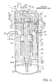
- FIG . 1 illustrates a longitudinal cross-sectional view of a scroll compressor 1 according to the present embodiment.
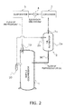
- FIG. 2 illustrates a schematic view of a refrigerant circuit to which the scroll compressor 1 according to the present embodiment as well as an oil separator 2, a condenser 3, an expansion mechanism 4, and evaporator 5 are provided.
- the refrigerant circuit moves and operates to perform a refrigeration cycle for circulating refrigerant.
- the scroll compressor 1 according to the present embodiment, as illustrated in FIG. 2 , is connected via a discharge tube 20 and an oil return passage 96 to the oil separator 2, which is disposed on the exterior of the scroll compressor 1.
- the oil separator 2 A more detailed description of the constituent components of the scroll compressor 1 as well as a more detailed description of the oil separator 2 shall be provided below.
- a casing 10 has a substantially cylindrical trunk casing part 11, a bowl-shaped upper wall part 12 hermetically welded to an upper end part of the trunk casing part 11, and a bowl-shaped bottom wall part 13 hermetically welded to a lower end part of the trunk casing part 11.
- the casing 10 is molded from a rigid member which is less prone to experience deformation or damage in a case where the pressure and temperature change on the interior and/or exterior of the casing 10.
- the casing 10 is installed such that an axial direction of the substantially cylindrical shape of the trunk casing part 11 runs along the vertical direction.
- the inside of the casing 10 accommodates: a compression mechanism 15 for compressing refrigerant; a drive motor 16 disposed below the compression mechanism 15; a drive shaft 17 disposed so as to extend in the up-down direction throughout the inside of the casing 10; and the like.
- An intake tube 19 (described below), the discharge tube 20, and the oil return passage 96 are hermetically joined to the casing 10.
- the compression mechanism 15 comprises a fixed scroll component 24 and an orbiting scroll component 26.
- the fixed scroll component 24 has a first end plate 24a, and a spiral-shaped (involute-shaped) first lap 24b formed in an upright manner on the first end plate 24a.
- a main suction hole (not shown) and an auxiliary suction hole (not shown) adjacent to the main suction hole are formed on the fixed scroll component 24.
- the main suction hole creates communication between the intake tube 19 (described below) and a compression chamber 40 (described below), and the auxiliary suction hole creates communication between a low-pressure space S2 (described below) and the compression chamber 40 (described below).
- a discharge hole 41 is formed on a center part of the first end plate 24a, and an expanded recess 42 communicating with the discharge hole 41 is formed on an upper surface of the first end plate 24a.
- the expanded recess 42 comprises a recess expanding in the horizontal direction and disposed in a concave manner on the upper surface of the first end plate 24a.
- a lid body 44 is securely fastened by a bolt 44a to the upper surface of the fixed scroll component 24 so as to close off the expanded recess 42.
- the lid body 44 forms a muffler space 45 composed of an expansion chamber for muting the operating sound of the compression mechanism 15.
- the fixed scroll component 24 and the lid body 44 are tightly joined interposed by a packing (not shown) and thereby tightly sealed.
- a first intercommunicating passage 46 communicating with the muffler space 45 and opening on a lower surface of the fixed scroll component 24 is formed on the fixed scroll component 24.
- the orbiting scroll component 26 comprises a second end plate 26a and a spiral-shaped (involute-shaped) second lap 26b formed in an upright manner on the second end plate 26a.
- a second bearing part 26c is formed on a lower surface center part of the second end plate 26a.
- An oil supply hole 63 is formed on the second end plate 26a.
- the oil supply hole 63 communicates between an upper surface outer peripheral part of the second end plate 26a and a space on the inside of the second bearing part 26c.
- the first lap 24b and the second lap 26b mesh together, whereby the fixed scroll component 24 and the orbiting scroll component 26 form the compression chamber 40 enclosed by the first end plate 24a, the first lap 24b, the second end plate 26a, and the second lap 26b.
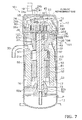
- the main frame 23 is installed below the compression mechanism 15 and is hermetically joined to an inner wall of the casing 10 at an outer peripheral surface thereof. For this reason, the interior of the casing 10 is subdivided into a high-pressure space S1 below the main frame 23, and the low-pressure space S2 above the main frame 23.
- the main frame 23 has a main frame recess 31 disposed in a concave manner on an upper surface of the main frame 23, and a first bearing part 32 extending downward from a lower surface of the main frame 23.
- a first bearing hole 33 penetrating in the up-down direction is formed in the first bearing part 32.
- the fixed scroll component 24 is bolted or otherwise securely situated on the main frame 23, and the orbiting scroll component 26 is clamped together with the fixed scroll component 24 interposed by an Oldham coupling 39 (described below).
- a second intercommunicating passage 48 penetrating in the up-down direction is formed on an outer peripheral part of the main frame 23.
- the second intercommunicating passage 48 communicates with the first intercommunicating passage 46 on the upper surface of the main frame 23, and communicates with the high-pressure space S1 via a discharge port 49 on the lower surface of the main frame 23.
- the Oldham coupling 39 is a ring-shaped member for preventing the orbiting scroll component 26 from engaging in revolving motion, and is fitted into an oblong-shaped Oldham groove 26d formed on the main frame 23. (5) Drive motor
- the drive motor 16 is a brushless DC motor installed below the main frame 23.
- the drive motor 16 comprises a stator 51 fixed to the inner wall of the casing 10, and a rotor 52 provided with a slight clearance and accommodated so as to be able to rotate on the inside of the stator 51.
- a copper wire is wound around teeth of the stator 51 and a coil end 53 is formed thereabove and therebelow.
- An outer peripheral surface of the stator 51 is provided with a core-cut part formed over a lower end surface from an upper end surface of the stator 51 so as to be notched at a plurality of points, placed at predetermined intervals in the circumferential direction.
- the core-cut part forms a motor cooling passage 55 extending in the up-down direction between the trunk casing part 11 and the stator 51.
- the rotor 52 is coupled to the orbiting scroll component 26 via a drive shaft 17 (described below) in a center of rotation thereof.
- a secondary frame 60 is disposed below the drive motor 16.
- the secondary frame 60 is fixed to the trunk casing part 11 and has a third bearing part 60a.
- An oil separation plate 73 is a plate-shaped member installed below the drive motor 16 within the casing 10, and fixed to an upper surface side of the secondary frame 60.
- the oil separation plate 73 separates the lubricating oil included in the descending compressed refrigerant.
- the lubricating oil separated out falls to an oil reservoir P at a bottom part of the casing 10.
- the drive shaft 17 is coupled to the compression mechanism 15 and to the drive motor 16, and is disposed so as to extend in the up-down direction throughout the inside of the casing 10.
- a lower end part of the drive shaft 17 is positioned at the oil reservoir P.
- An oil supply path 61 penetrating in an axial direction is formed in the interior of the drive shaft 17.
- the oil supply path 61 communicates with an oil chamber 83 formed of an upper end surface of the drive shaft 17 and a lower surface of the second end plate 26a.
- the oil chamber 83 communicates with a sliding part of the fixed scroll component 24 and the orbiting scroll component 26 (hereinafter simply called the "sliding part of the compression mechanism 15"), via the oil supply hole 63 of the second end plate 26a, and ultimately leads to the low-pressure space S2.
- the drive shaft 17 has on the interior thereof a first horizontal oil supply hole 61a, a second horizontal oil supply hole 61b, and a third horizontal oil supply hole 61c, for supplying lubricating oil to the first bearing part 32, the third bearing part 60a, and the second bearing part 26c, respectively.
- the lubricating oil ascending through the oil supply path 61 is supplied to the first horizontal oil supply hole 61a, the second horizontal oil supply hole 61b, and the third horizontal oil supply hole 61c, and lubricates a sliding bearing part of the drive shaft 17.
- An ejector mechanism 91 is positioned below the discharge port 49 opening on the lower surface of the main frame 23.
- the ejector mechanism 91 comprises a gas guide 92 and a constricted-flow plate 93.
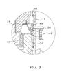
- FIG. 3 provides a more detailed illustration of the ejector mechanism 91 set forth in FIG. 1 .
- FIGS. 4 and 5 illustrate perspective views of the gas guide 92 and the constricted-flow plate 93, respectively, constituting the ejector mechanism 91.
- FIG. 6 illustrates a perspective view of the gas guide 92 combination with the constricted-flow plate 93.
- the gas guide 92 comprises a first flow path-forming part 92a, two first side wall parts 92b, and two outer wall parts 92c.
- Each of the two first side wall parts 92b is provided extending from both end parts of the first flow path-forming part 92a
- each of the two outer wall parts 92c is provided extending from both end parts of each of the first side wall parts 92b.
- the outer wall parts 92c have a surface which matches the shape of the inner wall of the casing 10, and the gas guide 92 can be tightly joined in a complete manner to the inner wall surface of the casing 10 at the outer wall parts 92c.
- the first flow path-forming part 92a and the first side wall parts 92b, together with the inner wall of the casing 10, form a space which opens at an upper end and a lower end.
- the upper end of the gas guide 92 as is illustrated in FIG. 3 , is in contact with the lower surface of the main frame 23, and therefore the space formed between the gas guide 92 and the casing 10 serves as a flow path for refrigerant, the flow path communicating from the second intercommunicating passage 48 via the discharge port 49.
- the shape of the gas guide 92 as illustrated in FIG. 3 represents the shape of the longitudinal cross-section of the first flow path-forming part 92a.
- the constricted-flow plate 93 comprises a second flow path-forming part 93a and two second side wall parts 93b.
- the two second side wall parts 93b are provided each extending from both end parts of the second flow path-forming part 93a.
- Each of the second side wall parts 93b can be tightly joined to each of the first side wall parts 92b of the gas guide 92, whereby the constricted-flow plate 93 can be combined with the gas guide 92, as illustrated in FIG. 6 .
- the shape of the constricted-flow plate 93 illustrated in FIG. 3 represents the shape of the longitudinal cross-section of the second flow path-forming part 93a.
- the second flow path-forming part 93a is positioned between the casing 10 and the first flow path-forming part 92a of the gas guide 92.
- the gap between the first flow path-forming part 92a of the gas guide 92 and the second flow path-forming part 93a of the constricted-flow plate 93 gradually narrows as the gap advances downward from above.
- a narrowed part 94 is formed where the gap between the first flow path-forming part 92a and the second flow path-forming part 93a reaches a minimum.
- the refrigerant having flowed in from the second flow path-forming part 48 increases in flow rate upon passing through the narrowed part 94, and therefore a space formed by the gas guide 92, the constricted-flow plate 93, and the casing 10 forms a refrigerant-accelerating flow path 95a.
- the space between the constricted-flow plate 93 and the casing 10 forms a part of an oil suction flow path 95b communicating with the oil return passage 96.
- the oil suction flow path 95b merges with the refrigerant-accelerating flow path 95a at an intercommunicating space 48b.
- An upper end part of the constricted-flow plate 93 is in contact with the casing 10, and therefore the refrigerant flowing through the refrigerant-accelerating flow path 95a merges with the oil suction flow path 95b at a point where the refrigerant has passed through the narrowed part 94. (10) Oil separator
- the oil separator 2 has a function for separating the lubricating oil from the refrigerant and returning the separated lubricating oil to the high-pressure space S1 within the casing 10 via the oil return passage 96, so as to prevent the compressed refrigerant discharged from the discharge tube 20 of the scroll compressor 1 from flowing into the exterior refrigerant circuit in a state where the compressed refrigerant includes lubricating oil.
- the oil separator 2 has: a tank 2a internally provided with a mechanism for separating out the lubricating oil from the refrigerant; an inlet tube 2b for introducing the refrigerant containing the lubricating oil, into the interior of the tank 2a from the discharge tube 20 of the scroll compressor 1; an outlet tube 2c for supplying, from the tank 2a to the exterior refrigerant circuit, the refrigerant from which the lubricating oil has been separated out; and the oil return passage 96, serving as a flow path for returning, to the high-pressure space S1 within the casing 10, the lubricating oil having been separated out from the refrigerant.
- the oil return passage 96 is joined to a bottom part of the tank 2a.
- the intake tube 19 is a member for guiding the refrigerant to the compression mechanism 15, and is hermetically fitted into the upper wall part 12 of the casing 10.
- the discharge tube 20 is a member for discharging the refrigerant from the casing 10, and is hermetically fitted to a position in the high-pressure space 81 in the bunk casing part 11 of the casing 10.
- the oil return passage 96 is a tube for returning, to the high-pressure space S1 in the trunk casing part 11 of the casing 10, the lubricating oil separated out by the oil separator 2 from the refrigerant compressed by the compression mechanism 15. As is illustrated in FIG. 3 , the oil return passage 96 is joined to the casing 10 at a position above the lower end of the constricted-Bow plate 93.
- the refrigerant is supplied to the compression chamber 40 of the compression mechanism 15 from the intake tube 19 by way of the main suction hole, or from the low-pressure space S2 by way of the auxiliary suction hole.
- the orbiting motion of the orbiting scroll component 26 causes the compression chamber 40 to move from the outer peripheral part of the fixed scroll component 24 toward the center part, while also causing the volume to gradually be reduced.
- the refrigerant inside the compression chamber 40 is compressed and discharged from the discharge hole 41 to the muffler space 45.
- the compressed refrigerant flows from the discharge port 49 into the high-pressure space S1 by way of the first intercommunicating passage 46 and the second intercommunicating passage 48, and passes through the ejector mechanism 91 to ultimately be discharged from the discharge tube 20.
- the high-pressure refrigerant discharged from the scroll compressor 1 is supplied to the exterior refrigerant circuit after the lubricating oil has been separated out therefrom in the oil separator 2, and is introduced into the intake tube 19 of the scroll compressor 1 by way of the condenser 3, the expansion mechanism 4, and the evaporator 5.
- the lubricating oil stored in the oil reservoir P ascends through the oil supply path 61 of the drive shaft 17, due to the centrifugal pump action and the high-low pressure difference, and is supplied to the sliding part of the compression mechanism 15 by way of the oil chamber 83 and the oil supply hole 63. Because the sliding part is in contact with the compression chamber 40, the lubricating oil supplied to the sliding of the compression mechanism 15 is supplied to the compression chamber 40. As a result thereof, the lubricating oil supplied to the compression chamber 40 is compressed together with the refrigerant.
- the lubricating oil having lubricated the sliding part in the first bearing part 32 and the second bearing part 26, leaks out to the high-pressure space S1 from the lower end of the first bearing part 32, and is supplied to the high-pressure space S1 via an oil passage (not shown) which is formed in the main frame 23 and communicates with the main frame recess 31 and the high-pressure space S1.
- the high-pressure refrigerant discharged from the scroll compressor 1 contains lubricating oil.
- the high-pressure refrigerant containing the lubricating oil discharged from the scroll compressor 1 is taken to the interior of the tank 2a from the inlet tube 2b of the oil separator 2, and the lubricating oil is separated out.
- Centrifugation is an example of a scheme for separating out the lubricating oil from the refrigerant. With centrifugation, an orbiting plate is disposed in the interior of the tank 2a, and the refrigerant is made to perform an orbiting motion; the centrifugal force causes droplets of the lubricating oil included in the refrigerant to be separated out.
- the lubricating oil separated out from the refrigerant is stored in the bottom part of the tank 2a, and the refrigerant from which the lubricating oil has been separated out is supplied from the outlet tube 2c to the exterior refrigerant circuit.
- the lubricating oil stored in the bottom part of the tank 2a is returned to the high-pressure space S1 in the interior of the scroll compressor 1, via the oil return passage 96. A description of the process therefor shall now be provided.
- the refrigerant compressed by the compression mechanism 15 passes through the ejector mechanism 91 and is ultimately discharged from the discharge tube 20.
- the refrigerant when passing through the ejector mechanism 91, flows through the refrigerant-accelerating flow path 95a.
- the flow rate of the refrigerant is increased.
- the refrigerant in the refrigerant-accelerating flow path 95a merges with the oil suction flow path 95b at a point where the refrigerant has passed through the narrowed part 94, a negative pressure is generated in the oil suction flow path 95b due to an ejector effect.
- the lubricating oil inside the oil return passage 96 which communicates with the oil suction flow path 95b, is thereby sucked into the oil suction flow path 95b.
- the lubricating oil sucked into the oil suction flow path 95b merges into the flow of refrigerant in the refrigerant-accelerating flow path 95a, falls through the high-pressure space S1, and is supplied to the oil reservoir P in the bottom part of the casing 10.
- the ejector effect generated when the refrigerant compressed by the compression mechanism 15 passes through the ejector mechanism 91 disposed in the high-pressure space S1 inside the casing 10 causes the lubricating oil separated out by the oil separator 2 to be sucked into the high-pressure space S1 from the oil return passage 96.
- the scroll compressor 1 according to the present embodiment makes it possible to prevent the as-yet uncompressed refrigerant from being heated and expanded by the high-temperature lubricating oil, because, in the scroll compressor 1 according to the present embodiment the high-temperature lubricating oil separated out by the oil separator is not returned to a space led with the as-yet uncompressed refrigerant (for example, a suction tube for the refrigerant of the compressor). As such, the scroll compressor 1 according to the present embodiment makes it possible to suppress any decline in volumetric efficiency of the compressor.
- the scroll compressor 1 makes it possible to achieve a reduction in costs by reducing the number of components in the compressor.
- the ejector mechanism 91 which has no moving parts, is used order to realize a mechanism whereby lubricating oil is sucked into the high-pressure space S from the oil return passage 96.
- the scroll compressor 1 according to the present embodiment has an oil return mechanism which is simple to set up and maintain.
- the scroll compressor 1 provided with the compression mechanism 15, constituted of the fixed scroll component 24 and the orbiting scroll component 26, is used as the compressor, but a compressor provided with a different compression mechanism may also be used.
- a rotary-type compressor and/or a screw-type compressor may be used.
- the oil separator 2 is disposed on the exterior of the casing 10 of the scroll compressor 1, but an oil separation mechanism equivalent to the oil separator 2 may also be disposed on the interior of the casing 10. This makes it possible to render the refrigerant circuit more compact.
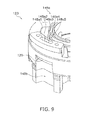
- a description of a compressor according to a second embodiment of the present invention shall now be provided, with reference to FIGS. 7 to 10 .
- a scroll compressor 101 according to the present embodiment has identical configurations, operations, and features in common with the scroll compressor 1 according to the first embodiment.
- the description shall focus on the points of disparity between the scroll compressor 101 according to the present embodiment and the scroll compressor 1 according to the first embodiment.
- FIG 7 illustrates a longitudinal cross-sectional view of the scroll compressor 101 according to the present embodiment
- FIG. 8 illustrates an enlarged cross-sectional view of the vicinity of an ejector mechanism 191 used in the present embodiment
- FIG. 9 and 10 illustrate an external view and a cross-sectional view, respectively of a main frame 123 used in the present embodiment.
- constituent elements identical to those of the scroll compressor 1 according to the first embodiment have been assigned reference numerals identical to those in FIG. 1 .
- the main frame 123 has a second intercommunicating passage 148.
- the second intercommunicating passage 148 communicates with the first intercommunicating passage 46 on an upper surface of the main frame 123, and communicates with the high-pressure space S1 via the discharge port 49 on a lower surface of the main frame 123.
- the second intercommunicating passage 148 comprises a frame through-hole 148a penetrating through the main frame 123 in the vertical direction, and an intercommunicating space 148b positioned below the frame through-hole 148a and formed between an outer peripheral surface of the main frame 123 and the inner wall surface of the trunk casing part 11.
- the frame through-hole 148a has a plurality of interlinking through-holes 148a1, 148a2, ... formed along a circumferential direction of the main frame 123.
- a lower end part of each of the through-holes 148a1, 148a2, ... has a truncated cone shape oriented vertically downward. More specifically, the horizontal surface area of the lower end parts of each of the through-holes 148a1, 148a2, ... gradually becomes smaller proceeding downward from above in the vertical direction.
- the main frame 123 has a tapered part 129.
- the tapered part 129 is a surface which is formed in the intercommunicating space 148b and is tilted inward in the radial direction from the outside in the radial direction of the trunk casing part 11 as the surface proceeds downward from above in the vertical direction.
- the tapered part 129 forms a part of an oil suction flow path 195b with the inner wall surface of the trunk casing part 11.
- the oil suction flow path 195b merges with a refrigerant-accelerating flow path 195a in the intercommunicating space 148b.
- An oil return passage 196 communicates with the oil suction flow path 195b.
- An upper end of the oil return passage 196 is positioned on an upper end of the tapered part 129.
- the frame through-hole 148a and the intercommunicating space 148b constitute the refrigerant-accelerating flow path 195a.
- a lower end of the frame through-hole 148a is a narrowed part 194 where a flow path cross-sectional area of the refrigerant-accelerating flow path 195a reaches a minimum.
- the lubricating oil within the oil return passage 196 is thereby sucked into the oil suction flow path 195b.
- the lubricating oil sucked into the oil suction flow path 195b flows into the refrigerant-accelerating flow path 195a, thereafter falls through the high-pressure space S1, and is supplied to the oil reservoir P of the bottom part of the casing 10.
- the main frame 123 has the frame through-hole 148a and the narrowed part 194.
- the high-pressure refrigerant compressed by the compression mechanism 15 flows into the frame through-hole 148a.
- the frame through-hole 148a communicates with the high-pressure space S1.
- the refrigerant-accelerating flow path 195a comprises the frame through-hole 148a and the intercommunicating space 148b formed from the trunk casing part 11 and the main frame 123.
- the oil suction flow path 195b is formed from the tapered part 129 of the main frame 123 and the trunk casing part 11.
- the present embodiment it is possible to mechanically process the main frame 123 to form the frame through-hole 148a having the narrowed part 194. This makes it possible to increase the shape accuracy of the narrowed part 194. As such, in the present embodiment, it possible to curb any variance in the suction force imparted by the ejector mechanism 191.
- the scroll compressor 1 in the scroll compressor 1 according to the first embodiment, a concern is presented in that the refrigerant yet to pass through the narrowed part 94 may leak out from a gap between the gas guide 92 and the main frame 23.
- the refrigerant compressed by the compression mechanism 15 when flowing through the refrigerant-accelerating flow path 195a, will reliably pass through the narrowed part 194; therefore, no concern is presented that the refrigerant having not yet passed through the narrowed part 194 will leak out.
- each of the through-holes 148a1, 148a2, ... constituting the frame through-hole 148a has, at the lower end part, a truncated cone shape oriented downward in the vertical direction, but it is possible for at least one through-hole from among the through-holes 148a1 148a2, ... to have, at the lower end part, a truncated cone shape oriented downward in the vertical direction.
- the frame through-hole 148a has the narrowed part 194.
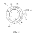
- a description of a compressor according to a third embodiment of the present invention shall now be provided, with reference to FIGS. 11 to 13 .
- a scroll compressor 201 according to the present embodiment has identical configurations, operations, and features in common with the scroll compressor 101 according to the second embodiment.
- the description shall focus on the points of disparity between the scroll compressor 201 according to the present embodiment and the scroll compressor 101 according to the second embodiment.
- FIG. 11 illustrates a longitudinal cross-sectional view of the scroll compressor 201 according to the present embodiment.
- FIG. 12 illustrates an enlarged cross-sectional view of the vicinity of an ejector mechanism 291 used in the present embodiment.
- FIG. 13 illustrates a top view of a fixed scroll component 224 used in the present embodiment.
- constituent elements identical to those of the scroll compressor 101 according to the second embodiment have been assigned reference numerals identical to those in FIG. 7 .
- a casing 210 has a trunk casing part 211 onto which an intake tube 219 is hermetically fitted, as well as an upper wall part 212 onto which a discharge tube 220 is hermetically fitted at an upper surface thereof. Refrigerant is guided to the interior of the casing 210 via the intake tube 219, compressed by the compression mechanism 215, and discharged to the exterior of the casing 210 via the discharge tube 220.
- a fixed scroll component 224 of a compression mechanism 215, as is illustrated in FIG. 11 , has at an outer peripheral part an upper refrigerant passage 297a penetrating through in the vertical direction; and, as is illustrated in FIG. 12 , has at the outer peripheral part an upper oil release hole 296a penetrating through in the vertical direction.
- the upper refrigerant passage 297a and the upper oil release hole 296a communicate with an oil separation space S3.
- the oil separation space S3 is a space on the interior of the casing 21 which is above the compression mechanism 215.
- the oil separation space S3 is a space to which refrigerant gas compressed by the compression mechanism 215 is discharged.
- the fixed scroll component 224 has an interior discharge tube 230.
- One of the end parts of the interior discharge tube 230 is connected to an opening part on an upper side of the upper refrigerant passage 297a, and the other end part is positioned in the oil separation space S3.
- the interior discharge tube 230 is an L-shaped tube which is elongated upward in the vertical direction from the opening part of the upper refrigerant passage 297a, caused to curve above the oil separation space S3, and elongated in the horizontal direction along a direction tangent to the outer periphery of the casing 210.
- a main frame 223, as is illustrated in FIG. 12 has a second intercommunicating passage 248.
- the second intercommunicating passage 248 communicates with the first intercommunicating passage 46 of the compression mechanism 215 on an upper surface of the main frame 223, and communicates with the high-pressure space S1 via the discharge port 49 on a lower surface of the main frame 223.
- the second intercommunicating passage 248 comprises a frame through-hole 248a penetrating through the main frame 223 in the vertical direction, and an intercommunicating space 248b between an outer peripheral surface of the main frame 223 and an inner wall surface of the trunk casing part 211, the intercommunicating space 248b being positioned below the frame through-hole 248a.
- the frame through-hole 248a has at a lower end part a narrowed part 294 where the cross-sectional area reaches a minimum.
- the main frame 223, as is illustrated in FIG. 11 has, at an outer peripheral part, a lower refrigerant passage 297b penetrating through in the vertical direction, and, as is illustrated in FIG. 12 , has a lower oil release hole 296b penetrating through in the vertical direction.
- the lower refrigerant passage 297b communicates with an upper refrigerant passage 297a
- the lower oil release hole 296b communicates with an upper oil release hole 296a.
- the lower refrigerant passage 297b and the lower oil release hole 296b communicate with the high-pressure space S1 which is below the main frame 223.
- the lower oil release hole 296b is positioned in the vicinity of the frame through-hole 248a.
- the ejector mechanism 29 comprises a refrigerant-accelerating flow path 295a, an oil suction flow path 295b, and the narrowed part 294.
- the refrigerant-accelerating flow path 295a comprises the frame through-hole 248a and an intercommunicating space 248b.
- the frame through-hole 248a has the narrowed part 294.
- a space on the interior of the upper oil release hole 296a and the lower oil release hole 296b forms a part of the oil suction flow path 295b.
- the oil suction flow path 295b merges with the refrigerant-accelerating flow path 295a in the intercommunicating space 248b.
- compressed refrigerant discharged from the compression mechanism 215 into the high-pressure space S1 passes through the lower refrigerant passage 297b of the main frame 223 and the upper refrigerant passage 297a of the fixed scroll component 224 prior to being discharged to the exterior of the casing 210, and flows into the interior discharge tube 230. Thereafter, the compressed refrigerant is discharged from the interior discharge tube 230 into the oil separation space S3.
- the compressed refrigerant as is illustrated in FIG. 13 , is discharged at the outer peripheral part of the fixed scroll component 224, along a direction tangent to the outer periphery of the casing 210.
- the lubricating oil included in the compressed refrigerant is separated out by the centrifugal force created by the spinning flow, and is flung toward the inner wall surface of the upper wall part 212.
- the lubricating oil, flung out and having stuck to the inner wall surface of the upper wall part 212 falls through the inside of the oil separation space S3, and is released into the high-pressure space S1 from the upper oil release hole 296a of the fixed scroll component 224.
- the compressed refrigerant from which the lubricating oil has been separated out is discharged to the exterior of the casing 210 via the discharge tube 220.
- a suction action from the oil separation space S3 to the oil suction flow path 295b, i.e., to the lower oil release hole 296b is thereby generated.
- the lubricating oil separated out from the compressed refrigerant in the oil separation space S3 is sucked into the lower oil released hole 296b by way of the upper oil release hole 296a, and ultimately arrives at the intercommunicating space 248b. Thereafter, the lubricating oil falls through the high-pressure space S1 and is supplied to the oil reservoir P in the bottom part of the casing 210.
- the lubricating oil separated out in the oil separation space S3 is not stored in the bottom part of the oil separation space S3 but rather is rapidly released into the high-pressure space S1 by the ejector mechanism 291.
- the scroll compressor 201 according to the present embodiment makes it possible to curb any decline in the efficiency at which the lubricating oil is separated out.
- the lubricating oil is separated out from the compressed refrigerant in the oil separation space S3 inside the casing 210, and accordingly there is no need to install on the exterior of the casing 210 the oil separator 2 used in the second embodiment.
- the scroll compressor 201 according to the present embodiment makes it possible to reduce costs.
- the compressor according to the present invention returns high-temperature lubricating oil separated out by the oil separator to the high-pressure space in the interior of the compressor, making it possible to suppress any decline in volumetric efficiency.
- employing the compressor according to the present invention in a refrigeration cycle makes it possible to operate an air conditioner or other refrigeration device in an efficient manner.
Abstract
Description
- The present invention relates to a compressor and to a refrigeration device; more particularly, the present invention relates to a compressor provided with a mechanism for returning, to the compressor, lubricating oil included in refrigerant discharged from the compressor, as well as to a refrigeration device provided with the compressor.
- In general, in a compressor constituting a refrigerant circuit for performing a refrigeration cycle, lubricating oil (refrigerator oil) is used in order to enhance the lubricating performance of a sliding part of a compression mechanism in the interior of the compressor. For this reason, the lubricating oil is included in refrigerant discharged from the compressor. However, when the refrigerant containing the lubricating oil flows into a refrigerant circuit on the exterior of the compressor, a problem emerges in that there is a deficit of lubricating oil in the interior of the compressor and poor lubrication of the sliding part, and in that the lubricating oil sticks to a heat transfer tube in the interior of a condenser and a heat transfer action is inhibited, and others. In view whereof, there has been proposed in the past a configuration for separating out the lubricating oil from the refrigerant compressed in the compressor and for returning the lubricating oil to the compressor, in order to prevent the refrigerant containing the lubricating oil from circulating through the refrigerant circuit.
- For example, Patent Literature 1 (Japanese Unexamined Publication No.
5-223074 - <Technical Problem>
- However, in a conventional scroll compressor, lubricating oil which has been compressed and brought to a high temperature will be returned to a space in the interior of the compressor filled with as-yet uncompressed, low-temperature refrigerant. For this reason, in the conventional scroll compressor, the as-yet uncompressed, low-temperature refrigerant is heated by the high-temperature lubricating oil, and a problem emerges in that compressing the refrigerant, which has been expanded by the heating, leads to a considerable decline in volumetric efficiency.
- An objective of the present invention is to provide a compressor whereby any decline in volumetric efficiency can be suppressed in a process for returning, to the interior of the compressor, high-temperature lubricating oil having been separated out by an oil separator.
- A compressor according to a first aspect of the present invention is provided with a casing, a compression mechanism, an oil separator, and an oil return passage. The casing stores lubricating oil in a bottom part. The compression mechanism is accommodated in the interior of the casing. The oil separator is installed on the exterior of the casing. The oil separator separates out lubricating oil fro high-pressure refrigerant discharged from the compression mechanism. The lubricating oil separated out by the oil separator flows through the oil return, passage. The oil return passage communicates with a high-pressure space formed in the interior of the casing. The high-pressure refrigerant flows into the high-pressure space.
- In the compressor according to the first aspect, the lubricating oil is separated out by the oil separator from the refrigerant compressed by the compression mechanism, and the separated-out lubricating oil is returned directly to the high-pressure space in the interior of the casing by way of the oil return passage. This high-pressure space is a space where refrigerant compressed by the compression mechanism is discharged. As such, in the compressor according to the first aspect, unlike the conventional compressor, the lubricating oil separated out by the oil separator will not be returned to a low-pressure space filled with as-yet uncompressed refrigerant, and therefore the as-yet uncompressed refrigerant will not be heated and expanded by the high-temperature lubricating oil. This makes it possible for any decline in volumetric efficiency to be suppressed in the compressor according to the first aspect.
- Further, in the compressor according to the first aspect, there is little difference in pressure between the high-pressure space and the oil return passage, through which the lubricating oil separated out by the oil separator flows. As such, there is no longer a need for a capillary tubing or other pressure adjustment mechanism, which has been necessary in a conventional compression mechanism in order to return only a suitable amount of lubricating oil to the low-pressure space filled with as-yet uncompressed refrigerant. This makes it possible to achieve a cost reduction based on a reduced number of components in the compressor according to the first aspect.
- A compressor according to a second aspect of the present invention is the compressor according to the first aspect, further provided with an ejector mechanism formed in the high-pressure space. The ejector mechanism has a refrigerant-accelerating flow path and an oil suction flow path. The high-pressure refrigerant flows in the refrigerant-accelerating flow path via a narrowed part, whereby a flow rate of the high-pressure refrigerant is increased. The oil suction flow path communicates with the oil return passage, the lubricating oil being sucked from the oil return passage into the oil suction flow path. The oil suction flow path merges with the refrigerant-accelerating flow path.
- In the compressor according to the second aspect, the flow rate of the refrigerant passing through the narrowed part of the refrigerant-accelerating flow path of the ejector mechanism is increased, and a negative pressure is generated due to an ejector effect in the oil suction flow path merging with the refrigerant-accelerating flow path, wherefore the lubricating oil is sucked in to the oil suction flow path from the oil return passage, and the sucked-in lubricating oil is supplied to the refrigerant-accelerating flow path. This makes it possible to increase the amount of lubricating oil returned to the interior of the compressor in the compressor according to the second aspect.
- A compressor according to a third aspect of the present invention is the compressor according to the second aspect, wherein the oil suction flow path merges with the refrigerant-accelerating flow path in a substantially parallel manner.
- In the compressor according to the third aspect, because the oil suction flow path merges with the refrigerant-accelerating flow path in a substantially parallel manner, the flow of lubricating oil in the oil suction flow path more readily merges into the refrigerant-accelerating flow path. For this reason, the lubricating oil sucked in to the oil suction flow path from the oil return passage is supplied more efficiently to the refrigerant-accelerating flow path. This makes it possible to further increase the amount of the lubricating oil returned to the interior of the compressor in the compressor according to the third aspect.
- A compressor according to a fourth aspect of the present invention is the compressor according to the second aspect or the third aspect, wherein the refrigerant-accelerating flow path is formed from a first flow-path-forming member and a second flow-path-forming member. The first flow-path-forming member, together with the casing, forms a flow path for the high-pressure refrigerant. The second flow-path-forming member, together with the first flow-path-forming member, forms the narrowed part. Further, the oil suction flow path is formed from the casing and the second flow-path-forming member.
- In the compressor according to the fourth aspect, the second flow-path-forming member is installed in the interior of a space (hereinbelow called a first space) surrounded by the first flow-path-forming member and the casing, thus forming the refrigerant-accelerating flow path and the oil suction flow path having the narrowed part. The first flow-path-forming member functions as a so-called gas guide member, and the refrigerant compressed by the compression mechanism is able to pass through the first space. The second flow-path-forming member functions as a so-called constricted-flow plate, and is installed such that a part of a flow path for the refrigerant in the first space is gradually narrowed. More specifically, the second flow-path-forming member, together with the first flow-path-forming member, forms a part of the refrigerant-accelerating flow path having the narrowed part. Further, a space (hereinbelow called a second space) is formed between the second flow-path-forming member and the casing. This second communicates with the first space at a point where the refrigerant has passed through the narrowed part, and is also the oil suction flow path communicating with the oil return passage. This makes it possible to use the first flow-path-forming member and the second flow-path-forming member to efficiently construct the ejector mechanism in the compressor according to the fourth aspect; and, therefore, to achieve a cost reduction based on a reduced number of components.
- A compressor according to a fifth aspect of the present invention is the compressor according to the second aspect or the third aspect, further provided with a main for supporting the compression mechanism. The main frame has a through-hole. The through-hole communicates with the high-pressure space, and is a space through which the high-pressure refrigerant discharged from the compression mechanism flows. The refrigerant-accelerating flow path includes the through-hole having the narrowed part as well as a space formed from the casing and the main frame. The oil suction flow path includes a space formed from the casing and the main frame.
- In the compressor according to the fifth aspect, the narrowed part is formed in the through-hole of the main frame. It is possible to mechanically process the main frame and thereby to provide a narrowed part having a high degree of shape accuracy. This makes it possible to curb any variance in the suction force imparted by the ejector mechanism in the compressor according to the fifth aspect.
- A compressor according to a sixth aspect of the present invention is provided with a casing, a compression mechanism, a main frame, and an ejector mechanism. The casing stores lubricating oil in a bottom part. The compression mechanism is accommodated in the interior of the casing. The compression mechanism compresses refrigerant and discharges high-pressure refrigerant. The main frame supports the compression mechanism. The ejector mechanism is accommodated in the interior of the casing. The casing has, in the interior thereof, a high-pressure space and an oil separation space. The high-pressure space is a space into which the high-pressure refrigerant discharged from the compression mechanism flows. The oil separation space is a different space than the high-pressure space, and is a space where lubricating oil is separated out from the high-pressure refrigerant The main frame has a through-hole and an oil release hole. The through-hole communicates with the high-pressure space, and is a space through which the high-pressure refrigerant discharged from the compression mechanism flows. The oil release hole communicates with the high-pressure space, and is a space where the lubricating oil separated out in the oil separation space flows. The ejector mechanism has a refrigerant-accelerating flow path, where the high-pressure refrigerant flows via a narrowed part whereby the flow rate of the high-pressure refrigerant, is increased, and an oil suction flow path, which merges with the refrigerant-accelerating flow path. The refrigerant-accelerating flow path includes a through-hole having a narrowed part as well as a space formed from the casing and the main frame. The oil suction flow path includes an oil release hole.
- In the compressor according to the sixth aspect, the lubricating oil separated out in the oil separation space inside the casing will not be stored in the bottom part of the oil separation space, but rather will be rapidly released into the high-pressure space by the ejector mechanism. This makes it possible to curb any decline in the efficiency at which the lubricating oil is separated out in the compressor according to the sixth aspect.
- A refrigeration device according to a seventh aspect of the present invention is provided with the compressor according to any of the first through sixth aspects, a condenser, an expansion mechanism, and an evaporator.
- In the compressor according to the seventh aspect, a refrigeration device can be provided with the compressor according to any of the first through sixth aspects. This makes it possible to suppress any decline in the coefficient of performance and the refrigeration capacity of the compressor in the refrigeration device according to the seventh aspect. <Advantageous Effects of Invention>
- The compressor according to the first aspect makes it possible to suppress any decline in volumetric efficiency, and possible to achieve a reduction in cost.
- The compressor according to the second aspect makes it possible to increase the amount of the lubricating oil returned to the interior of the compressor.
- The compressor according to the third aspect makes it possible to further increase the amount of the lubricating oil returned to the interior of the compressor.
- The compressor according to the fourth aspect makes it possible to achieve a reduction in cost.
- The compressor according to the fifth aspect makes it possible to curb any variance in the suction force imparted by the ejector mechanism.
- The compressor according to the sixth aspect makes it possible to curb any decline in the efficiency at which the lubricating oil is separated out.
- The refrigeration device according to the seventh aspect makes it possible to suppress any decline in the coefficient of performance and the refrigeration capacity of the compressor.
-
-
FIG. 1 is a longitudinal cross-sectional view of a scroll compressor according to a first embodiment of the present invention; -
FIG. 2 is a schematic view of a refrigerant circuit to which the scroll compressor according to the first embodiment of the present invention is provided; -
FIG 3 is a detailed longitudinal cross-sectional view of the vicinity of an ejector mechanism of the scroll compressor according to the first embodiment of the present invention; -
FIG. 4 is a perspective view of a gas guide constituting the ejector mechanism according to the first embodiment of the present invention; -
FIG. 5 is a perspective view of a constricted-flow plate for constituting the ejector mechanism according to the first embodiment of the present invention; -
FIG. 6 is a perspective view of the gas guide in combination with the constricted-flow plate according to the first embodiment of the present invention; -
FIG. 7 is a longitudinal cross-sectional view of a scroll compressor according to a second embodiment of the present invention; -
FIG. 8 is a detailed longitudinal cross-sectional view of the vicinity of an ejector mechanism of the scroll compressor according to the second embodiment of the present invention; -
FIG. 9 is an external view of a main frame according to the second embodiment of the present invention; -
FIG. 10 is a cross-sectional view of the main frame according to the second embodiment of the present invention; -
FIG. 11 is a longitudinal cross-sectional view of a scroll compressor according to a third embodiment of the present invention; -
FIG. 12 is a detailed longitudinal cross-sectional view of the vicinity of an ejector mechanism of the scroll compressor according to the third embodiment of the present invention; and -
FIG. 13 is a top view of a fixed scroll component of the scroll compressor according to the third embodiment of the present invention. - A description of the compressor according to the first embodiment of the present invention shall now be provided, with reference to
FIGS. 1 to 6 . The compressor in the present embodiment is a scroll compressor having two scrolling components in meshed engagement with each other, at least one of which engages in an orbital motion but not in a revolving motion, whereby refrigerant is compressed. -
FIG . 1 illustrates a longitudinal cross-sectional view of ascroll compressor 1 according to the present embodiment.FIG. 2 illustrates a schematic view of a refrigerant circuit to which thescroll compressor 1 according to the present embodiment as well as anoil separator 2, acondenser 3, an expansion mechanism 4, and evaporator 5 are provided. The refrigerant circuit moves and operates to perform a refrigeration cycle for circulating refrigerant. - The
scroll compressor 1 according to the present embodiment, as illustrated inFIG. 2 , is connected via adischarge tube 20 and anoil return passage 96 to theoil separator 2, which is disposed on the exterior of thescroll compressor 1. A more detailed description of the constituent components of thescroll compressor 1 as well as a more detailed description of theoil separator 2 shall be provided below. - A
casing 10 has a substantially cylindricaltrunk casing part 11, a bowl-shapedupper wall part 12 hermetically welded to an upper end part of thetrunk casing part 11, and a bowl-shapedbottom wall part 13 hermetically welded to a lower end part of thetrunk casing part 11. Thecasing 10 is molded from a rigid member which is less prone to experience deformation or damage in a case where the pressure and temperature change on the interior and/or exterior of thecasing 10. Thecasing 10 is installed such that an axial direction of the substantially cylindrical shape of thetrunk casing part 11 runs along the vertical direction. The inside of thecasing 10 accommodates: acompression mechanism 15 for compressing refrigerant; adrive motor 16 disposed below thecompression mechanism 15; adrive shaft 17 disposed so as to extend in the up-down direction throughout the inside of thecasing 10; and the like. An intake tube 19 (described below), thedischarge tube 20, and theoil return passage 96 are hermetically joined to thecasing 10. - The
compression mechanism 15 comprises a fixedscroll component 24 and anorbiting scroll component 26. - The fixed
scroll component 24 has afirst end plate 24a, and a spiral-shaped (involute-shaped)first lap 24b formed in an upright manner on thefirst end plate 24a. A main suction hole (not shown) and an auxiliary suction hole (not shown) adjacent to the main suction hole are formed on the fixedscroll component 24. The main suction hole creates communication between the intake tube 19 (described below) and a compression chamber 40 (described below), and the auxiliary suction hole creates communication between a low-pressure space S2 (described below) and the compression chamber 40 (described below). Adischarge hole 41 is formed on a center part of thefirst end plate 24a, and an expandedrecess 42 communicating with thedischarge hole 41 is formed on an upper surface of thefirst end plate 24a. The expandedrecess 42 comprises a recess expanding in the horizontal direction and disposed in a concave manner on the upper surface of thefirst end plate 24a. Alid body 44 is securely fastened by abolt 44a to the upper surface of the fixedscroll component 24 so as to close off the expandedrecess 42. By covering the expandedrecess 42, thelid body 44 forms amuffler space 45 composed of an expansion chamber for muting the operating sound of thecompression mechanism 15. The fixedscroll component 24 and thelid body 44 are tightly joined interposed by a packing (not shown) and thereby tightly sealed. Afirst intercommunicating passage 46 communicating with themuffler space 45 and opening on a lower surface of the fixedscroll component 24 is formed on the fixedscroll component 24. - The
orbiting scroll component 26 comprises asecond end plate 26a and a spiral-shaped (involute-shaped)second lap 26b formed in an upright manner on thesecond end plate 26a. Asecond bearing part 26c is formed on a lower surface center part of thesecond end plate 26a. Anoil supply hole 63 is formed on thesecond end plate 26a. Theoil supply hole 63 communicates between an upper surface outer peripheral part of thesecond end plate 26a and a space on the inside of thesecond bearing part 26c. Thefirst lap 24b and thesecond lap 26b mesh together, whereby the fixedscroll component 24 and theorbiting scroll component 26 form thecompression chamber 40 enclosed by thefirst end plate 24a, thefirst lap 24b, thesecond end plate 26a, and thesecond lap 26b. - The
main frame 23 is installed below thecompression mechanism 15 and is hermetically joined to an inner wall of thecasing 10 at an outer peripheral surface thereof. For this reason, the interior of thecasing 10 is subdivided into a high-pressure space S1 below themain frame 23, and the low-pressure space S2 above themain frame 23. Themain frame 23 has amain frame recess 31 disposed in a concave manner on an upper surface of themain frame 23, and afirst bearing part 32 extending downward from a lower surface of themain frame 23. Afirst bearing hole 33 penetrating in the up-down direction is formed in thefirst bearing part 32. The fixedscroll component 24 is bolted or otherwise securely situated on themain frame 23, and theorbiting scroll component 26 is clamped together with the fixedscroll component 24 interposed by an Oldham coupling 39 (described below). Asecond intercommunicating passage 48 penetrating in the up-down direction is formed on an outer peripheral part of themain frame 23. Thesecond intercommunicating passage 48 communicates with thefirst intercommunicating passage 46 on the upper surface of themain frame 23, and communicates with the high-pressure space S1 via adischarge port 49 on the lower surface of themain frame 23. - The
Oldham coupling 39 is a ring-shaped member for preventing theorbiting scroll component 26 from engaging in revolving motion, and is fitted into an oblong-shapedOldham groove 26d formed on themain frame 23. (5) Drive motor - The
drive motor 16 is a brushless DC motor installed below themain frame 23. Thedrive motor 16 comprises astator 51 fixed to the inner wall of thecasing 10, and arotor 52 provided with a slight clearance and accommodated so as to be able to rotate on the inside of thestator 51. - A copper wire is wound around teeth of the
stator 51 and acoil end 53 is formed thereabove and therebelow. An outer peripheral surface of thestator 51 is provided with a core-cut part formed over a lower end surface from an upper end surface of thestator 51 so as to be notched at a plurality of points, placed at predetermined intervals in the circumferential direction. The core-cut part forms amotor cooling passage 55 extending in the up-down direction between thetrunk casing part 11 and thestator 51. - The
rotor 52 is coupled to theorbiting scroll component 26 via a drive shaft 17 (described below) in a center of rotation thereof. - A
secondary frame 60 is disposed below thedrive motor 16. Thesecondary frame 60 is fixed to thetrunk casing part 11 and has athird bearing part 60a. - An
oil separation plate 73 is a plate-shaped member installed below thedrive motor 16 within thecasing 10, and fixed to an upper surface side of thesecondary frame 60. Theoil separation plate 73 separates the lubricating oil included in the descending compressed refrigerant. The lubricating oil separated out falls to an oil reservoir P at a bottom part of thecasing 10. - The
drive shaft 17 is coupled to thecompression mechanism 15 and to thedrive motor 16, and is disposed so as to extend in the up-down direction throughout the inside of thecasing 10. A lower end part of thedrive shaft 17 is positioned at the oil reservoir P. Anoil supply path 61 penetrating in an axial direction is formed in the interior of thedrive shaft 17. Theoil supply path 61 communicates with anoil chamber 83 formed of an upper end surface of thedrive shaft 17 and a lower surface of thesecond end plate 26a. Theoil chamber 83 communicates with a sliding part of the fixedscroll component 24 and the orbiting scroll component 26 (hereinafter simply called the "sliding part of thecompression mechanism 15"), via theoil supply hole 63 of thesecond end plate 26a, and ultimately leads to the low-pressure space S2. As such, when thedrive shaft 17 engages in an axial rotational motion, a centrifugal pump action and a high-low pressure difference cause the lubricating oil being stored in the oil reservoir P to flow upward through theoil supply path 61 and to be supplied to theoil chamber 83. Thereafter, the lubricating oil passes by way of theoil supply hole 63 and lubricates the sliding part of thecompression mechanism 15. - The
drive shaft 17 has on the interior thereof a first horizontaloil supply hole 61a, a second horizontaloil supply hole 61b, and a third horizontaloil supply hole 61c, for supplying lubricating oil to thefirst bearing part 32, thethird bearing part 60a, and thesecond bearing part 26c, respectively. The lubricating oil ascending through theoil supply path 61 is supplied to the first horizontaloil supply hole 61a, the second horizontaloil supply hole 61b, and the third horizontaloil supply hole 61c, and lubricates a sliding bearing part of thedrive shaft 17. - An
ejector mechanism 91 is positioned below thedischarge port 49 opening on the lower surface of themain frame 23. Theejector mechanism 91 comprises agas guide 92 and a constricted-flow plate 93.FIG. 3 provides a more detailed illustration of theejector mechanism 91 set forth inFIG. 1 .FIGS. 4 and5 illustrate perspective views of thegas guide 92 and the constricted-flow plate 93, respectively, constituting theejector mechanism 91.FIG. 6 illustrates a perspective view of thegas guide 92 combination with the constricted-flow plate 93. - The
gas guide 92, as is illustrated inFIG. 4 , comprises a first flow path-formingpart 92a, two firstside wall parts 92b, and twoouter wall parts 92c. Each of the two firstside wall parts 92b is provided extending from both end parts of the first flow path-formingpart 92a, and each of the twoouter wall parts 92c is provided extending from both end parts of each of the firstside wall parts 92b. Theouter wall parts 92c have a surface which matches the shape of the inner wall of thecasing 10, and thegas guide 92 can be tightly joined in a complete manner to the inner wall surface of thecasing 10 at theouter wall parts 92c. For this reason, in a case where thegas guide 92 has been tightly joined to the inner wall surface of thecasing 10, then the first flow path-formingpart 92a and the firstside wall parts 92b, together with the inner wall of thecasing 10, form a space which opens at an upper end and a lower end. The upper end of thegas guide 92, as is illustrated inFIG. 3 , is in contact with the lower surface of themain frame 23, and therefore the space formed between thegas guide 92 and thecasing 10 serves as a flow path for refrigerant, the flow path communicating from thesecond intercommunicating passage 48 via thedischarge port 49. The shape of thegas guide 92 as illustrated inFIG. 3 represents the shape of the longitudinal cross-section of the first flow path-formingpart 92a. - The constricted-
flow plate 93, as is illustrated inFIG. 5 , comprises a second flow path-formingpart 93a and two secondside wall parts 93b. The two secondside wall parts 93b are provided each extending from both end parts of the second flow path-formingpart 93a. Each of the secondside wall parts 93b can be tightly joined to each of the firstside wall parts 92b of thegas guide 92, whereby the constricted-flow plate 93 can be combined with thegas guide 92, as illustrated inFIG. 6 . The shape of the constricted-flow plate 93 illustrated inFIG. 3 represents the shape of the longitudinal cross-section of the second flow path-formingpart 93a. Specifically, the second flow path-formingpart 93a is positioned between thecasing 10 and the first flow path-formingpart 92a of thegas guide 92. - As is illustrated in
FIG. 3 , The gap between the first flow path-formingpart 92a of thegas guide 92 and the second flow path-formingpart 93a of the constricted-flow plate 93 gradually narrows as the gap advances downward from above. Herein, anarrowed part 94 is formed where the gap between the first flow path-formingpart 92a and the second flow path-formingpart 93a reaches a minimum. The refrigerant having flowed in from the second flow path-formingpart 48 increases in flow rate upon passing through the narrowedpart 94, and therefore a space formed by thegas guide 92, the constricted-flow plate 93, and thecasing 10 forms a refrigerant-acceleratingflow path 95a. - The space between the constricted-
flow plate 93 and thecasing 10 forms a part of an oilsuction flow path 95b communicating with theoil return passage 96. The oilsuction flow path 95b merges with the refrigerant-acceleratingflow path 95a at an intercommunicating space 48b. An upper end part of the constricted-flow plate 93 is in contact with thecasing 10, and therefore the refrigerant flowing through the refrigerant-acceleratingflow path 95a merges with the oilsuction flow path 95b at a point where the refrigerant has passed through the narrowedpart 94. (10) Oil separator - The
oil separator 2 has a function for separating the lubricating oil from the refrigerant and returning the separated lubricating oil to the high-pressure space S1 within thecasing 10 via theoil return passage 96, so as to prevent the compressed refrigerant discharged from thedischarge tube 20 of thescroll compressor 1 from flowing into the exterior refrigerant circuit in a state where the compressed refrigerant includes lubricating oil. - The
oil separator 2, as is illustrated inFIG. 2 , has: atank 2a internally provided with a mechanism for separating out the lubricating oil from the refrigerant; aninlet tube 2b for introducing the refrigerant containing the lubricating oil, into the interior of thetank 2a from thedischarge tube 20 of thescroll compressor 1; anoutlet tube 2c for supplying, from thetank 2a to the exterior refrigerant circuit, the refrigerant from which the lubricating oil has been separated out; and theoil return passage 96, serving as a flow path for returning, to the high-pressure space S1 within thecasing 10, the lubricating oil having been separated out from the refrigerant. Theoil return passage 96 is joined to a bottom part of thetank 2a. - The
intake tube 19 is a member for guiding the refrigerant to thecompression mechanism 15, and is hermetically fitted into theupper wall part 12 of thecasing 10. - The
discharge tube 20 is a member for discharging the refrigerant from thecasing 10, and is hermetically fitted to a position in the high-pressure space 81 in thebunk casing part 11 of thecasing 10. - The
oil return passage 96 is a tube for returning, to the high-pressure space S1 in thetrunk casing part 11 of thecasing 10, the lubricating oil separated out by theoil separator 2 from the refrigerant compressed by thecompression mechanism 15. As is illustrated inFIG. 3 , theoil return passage 96 is joined to thecasing 10 at a position above the lower end of the constricted-Bow plate 93. - A description of the motion and operation of the
scroll compressor 1 of the present embodiment shall now be provided. The description shall first relate to the flow of the refrigerant; thereafter, the process by which the lubricating oil is returned to the high-pressure space S1 of thescroll compressor 1 from theoil separator 2 by way of theoil return passage 96 shall be described. - The description shall first relate to the flow of the refrigerant. Firstly, when the
drive motor 16 is started up, thedrive shaft 17 begins to engage in an axial rotational motion in association with the rotation of therotor 52. The axial rotational force of thedrive shaft 17 is transmitted to theorbiting scroll component 26 via thesecond bearing part 26c. Theorbiting scroll component 26 is prohibited from engaging in revolving motion by theOldham coupling 39, and therefore engages in orbital motion, but not revolving motion, about a center of axial rotation of thedrive shaft 17. The refrigerant is supplied to thecompression chamber 40 of thecompression mechanism 15 from theintake tube 19 by way of the main suction hole, or from the low-pressure space S2 by way of the auxiliary suction hole. The orbiting motion of theorbiting scroll component 26 causes thecompression chamber 40 to move from the outer peripheral part of the fixedscroll component 24 toward the center part, while also causing the volume to gradually be reduced. As a result thereof, the refrigerant inside thecompression chamber 40 is compressed and discharged from thedischarge hole 41 to themuffler space 45. The compressed refrigerant flows from thedischarge port 49 into the high-pressure space S1 by way of thefirst intercommunicating passage 46 and thesecond intercommunicating passage 48, and passes through theejector mechanism 91 to ultimately be discharged from thedischarge tube 20. The high-pressure refrigerant discharged from thescroll compressor 1 is supplied to the exterior refrigerant circuit after the lubricating oil has been separated out therefrom in theoil separator 2, and is introduced into theintake tube 19 of thescroll compressor 1 by way of thecondenser 3, the expansion mechanism 4, and the evaporator 5. - During this compression operation of the refrigeration cycle, the lubricating oil stored in the oil reservoir P ascends through the
oil supply path 61 of thedrive shaft 17, due to the centrifugal pump action and the high-low pressure difference, and is supplied to the sliding part of thecompression mechanism 15 by way of theoil chamber 83 and theoil supply hole 63. Because the sliding part is in contact with thecompression chamber 40, the lubricating oil supplied to the sliding of thecompression mechanism 15 is supplied to thecompression chamber 40. As a result thereof, the lubricating oil supplied to thecompression chamber 40 is compressed together with the refrigerant. The lubricating oil, having lubricated the sliding part in thefirst bearing part 32 and thesecond bearing part 26, leaks out to the high-pressure space S1 from the lower end of thefirst bearing part 32, and is supplied to the high-pressure space S1 via an oil passage (not shown) which is formed in themain frame 23 and communicates with themain frame recess 31 and the high-pressure space S1. As such, the high-pressure refrigerant discharged from thescroll compressor 1 contains lubricating oil. - The high-pressure refrigerant containing the lubricating oil discharged from the
scroll compressor 1 is taken to the interior of thetank 2a from theinlet tube 2b of theoil separator 2, and the lubricating oil is separated out. Centrifugation is an example of a scheme for separating out the lubricating oil from the refrigerant. With centrifugation, an orbiting plate is disposed in the interior of thetank 2a, and the refrigerant is made to perform an orbiting motion; the centrifugal force causes droplets of the lubricating oil included in the refrigerant to be separated out. The lubricating oil separated out from the refrigerant is stored in the bottom part of thetank 2a, and the refrigerant from which the lubricating oil has been separated out is supplied from theoutlet tube 2c to the exterior refrigerant circuit. The lubricating oil stored in the bottom part of thetank 2a is returned to the high-pressure space S1 in the interior of thescroll compressor 1, via theoil return passage 96. A description of the process therefor shall now be provided. - The refrigerant compressed by the
compression mechanism 15 passes through theejector mechanism 91 and is ultimately discharged from thedischarge tube 20. The refrigerant, when passing through theejector mechanism 91, flows through the refrigerant-acceleratingflow path 95a. At such a time, because the flow path of the refrigerant is tightened in the narrowedpart 94, the flow rate of the refrigerant is increased. Because the refrigerant in the refrigerant-acceleratingflow path 95a merges with the oilsuction flow path 95b at a point where the refrigerant has passed through the narrowedpart 94, a negative pressure is generated in the oilsuction flow path 95b due to an ejector effect. The lubricating oil inside theoil return passage 96, which communicates with the oilsuction flow path 95b, is thereby sucked into the oilsuction flow path 95b. The lubricating oil sucked into the oilsuction flow path 95b merges into the flow of refrigerant in the refrigerant-acceleratingflow path 95a, falls through the high-pressure space S1, and is supplied to the oil reservoir P in the bottom part of thecasing 10. - In the
scroll compressor 1 according to the present embodiment, the ejector effect generated when the refrigerant compressed by thecompression mechanism 15 passes through theejector mechanism 91 disposed in the high-pressure space S1 inside thecasing 10 causes the lubricating oil separated out by theoil separator 2 to be sucked into the high-pressure space S1 from theoil return passage 96. This makes it possible to prevent the as-yet uncompressed refrigerant from being heated and expanded by the high-temperature lubricating oil, because, in thescroll compressor 1 according to the present embodiment the high-temperature lubricating oil separated out by the oil separator is not returned to a space led with the as-yet uncompressed refrigerant (for example, a suction tube for the refrigerant of the compressor). As such, thescroll compressor 1 according to the present embodiment makes it possible to suppress any decline in volumetric efficiency of the compressor. - Further, in the
scroll compressor 1 according to the present embodiment, there is no longer a need for a capillary tubing or other pressure adjustment mechanism, which has been necessary in a conventional compressor in order to return only a suitable amount of lubricating oil to the low-pressure space filled with as-yet uncompressed refrigerant. As such, thescroll compressor 1 according to the present embodiment makes it possible to achieve a reduction in costs by reducing the number of components in the compressor. - Also, in the
scroll compressor 1 according to the present embodiment, theejector mechanism 91, which has no moving parts, is used order to realize a mechanism whereby lubricating oil is sucked into the high-pressure space S from theoil return passage 96. As such, thescroll compressor 1 according to the present embodiment has an oil return mechanism which is simple to set up and maintain. - In the present embodiment, the
scroll compressor 1 provided with thecompression mechanism 15, constituted of the fixedscroll component 24 and theorbiting scroll component 26, is used as the compressor, but a compressor provided with a different compression mechanism may also be used. For example, a rotary-type compressor and/or a screw-type compressor may be used. - Further, in the present embodiment, the
oil separator 2 is disposed on the exterior of thecasing 10 of thescroll compressor 1, but an oil separation mechanism equivalent to theoil separator 2 may also be disposed on the interior of thecasing 10. This makes it possible to render the refrigerant circuit more compact. - A description of a compressor according to a second embodiment of the present invention shall now be provided, with reference to
FIGS. 7 to 10 . Ascroll compressor 101 according to the present embodiment has identical configurations, operations, and features in common with thescroll compressor 1 according to the first embodiment. Hereinbelow, the description shall focus on the points of disparity between thescroll compressor 101 according to the present embodiment and thescroll compressor 1 according to the first embodiment. -
FIG 7 illustrates a longitudinal cross-sectional view of thescroll compressor 101 according to the present embodiment,FIG. 8 illustrates an enlarged cross-sectional view of the vicinity of anejector mechanism 191 used in the present embodiment.FIG. 9 and10 illustrate an external view and a cross-sectional view, respectively of amain frame 123 used in the present embodiment. InFIGS. 7 to 10 , constituent elements identical to those of thescroll compressor 1 according to the first embodiment have been assigned reference numerals identical to those inFIG. 1 . - In the present embodiment, as is illustrated in
FIG. 7 , themain frame 123 has asecond intercommunicating passage 148. Similarly with respect to thesecond intercommunicating passage 48 in the first embodiment, thesecond intercommunicating passage 148 communicates with thefirst intercommunicating passage 46 on an upper surface of themain frame 123, and communicates with the high-pressure space S1 via thedischarge port 49 on a lower surface of themain frame 123. As is illustrated inFIG. 8 , thesecond intercommunicating passage 148 comprises a frame through-hole 148a penetrating through themain frame 123 in the vertical direction, and an intercommunicatingspace 148b positioned below the frame through-hole 148a and formed between an outer peripheral surface of themain frame 123 and the inner wall surface of thetrunk casing part 11. As is illustrated inFIGS. 9 and10 , the frame through-hole 148a has a plurality of interlinking through-holes 148a1, 148a2, ... formed along a circumferential direction of themain frame 123. As is illustrated inFIGS. 8 and10 , a lower end part of each of the through-holes 148a1, 148a2, ... has a truncated cone shape oriented vertically downward. More specifically, the horizontal surface area of the lower end parts of each of the through-holes 148a1, 148a2, ... gradually becomes smaller proceeding downward from above in the vertical direction. - In the present embodiment, the
main frame 123 has a taperedpart 129. As is illustrated inFIG 8 to 10 , thetapered part 129 is a surface which is formed in the intercommunicatingspace 148b and is tilted inward in the radial direction from the outside in the radial direction of thetrunk casing part 11 as the surface proceeds downward from above in the vertical direction. - A description of the constituent elements of the
ejector mechanism 191 in the present embodiment shall now be provided. As is illustrated inFIG. 8 , thetapered part 129 forms a part of an oilsuction flow path 195b with the inner wall surface of thetrunk casing part 11. The oilsuction flow path 195b merges with a refrigerant-acceleratingflow path 195a in the intercommunicatingspace 148b. Anoil return passage 196 communicates with the oilsuction flow path 195b. An upper end of theoil return passage 196 is positioned on an upper end of thetapered part 129. The frame through-hole 148a and the intercommunicatingspace 148b constitute the refrigerant-acceleratingflow path 195a. A lower end of the frame through-hole 148a is anarrowed part 194 where a flow path cross-sectional area of the refrigerant-acceleratingflow path 195a reaches a minimum. - A description of a process in the present embodiment by which the lubricating oil separated out by the
oil separator 2 is returned to the high-pressure space S1 by theejector mechanism 191 via theoil return passage 196 shall now be provided. The refrigerant compressed by thecompression mechanism 15, when flowing through the refrigerant-acceleratingflow path 195a, passes through thenarrowed part 194. At such a time, the flow path of the refrigerant is tightened, whereby the flow rate of the refrigerant is increased. A negative pressure is generated, due to the ejector effect, in the oilsuction flow path 195b merging with the refrigerant-acceleratingflow path 195a. The lubricating oil within theoil return passage 196 is thereby sucked into the oilsuction flow path 195b. The lubricating oil sucked into the oilsuction flow path 195b flows into the refrigerant-acceleratingflow path 195a, thereafter falls through the high-pressure space S1, and is supplied to the oil reservoir P of the bottom part of thecasing 10. - In the
scroll compressor 101 according to the present embodiment, themain frame 123 has the frame through-hole 148a and thenarrowed part 194. The high-pressure refrigerant compressed by thecompression mechanism 15 flows into the frame through-hole 148a. The frame through-hole 148a communicates with the high-pressure space S1. The refrigerant-acceleratingflow path 195a comprises the frame through-hole 148a and the intercommunicatingspace 148b formed from thetrunk casing part 11 and themain frame 123. The oilsuction flow path 195b is formed from thetapered part 129 of themain frame 123 and thetrunk casing part 11. - In the present embodiment, it is possible to mechanically process the
main frame 123 to form the frame through-hole 148a having the narrowedpart 194. This makes it possible to increase the shape accuracy of thenarrowed part 194. As such, in the present embodiment, it possible to curb any variance in the suction force imparted by theejector mechanism 191. - Further, in the
scroll compressor 1 according to the first embodiment, a concern is presented in that the refrigerant yet to pass through the narrowedpart 94 may leak out from a gap between thegas guide 92 and themain frame 23. However, in thescroll compressor 101 according to the present embodiment, the refrigerant compressed by thecompression mechanism 15, when flowing through the refrigerant-acceleratingflow path 195a, will reliably pass through thenarrowed part 194; therefore, no concern is presented that the refrigerant having not yet passed through thenarrowed part 194 will leak out. - Also, in the
scroll compressor 101 according to the present embodiment, there is no need to install the constricted-flow plate 93 used in thescroll compressor 1 according to the first embodiment. - In the
scroll compressor 101 according to the present embodiment, each of the through-holes 148a1, 148a2, ... constituting the frame through-hole 148a has, at the lower end part, a truncated cone shape oriented downward in the vertical direction, but it is possible for at least one through-hole from among the through-holes 148a1 148a2, ... to have, at the lower end part, a truncated cone shape oriented downward in the vertical direction. In the present modification example as well, the frame through-hole 148a has the narrowedpart 194. - A description of a compressor according to a third embodiment of the present invention shall now be provided, with reference to
FIGS. 11 to 13 . Ascroll compressor 201 according to the present embodiment has identical configurations, operations, and features in common with thescroll compressor 101 according to the second embodiment. Hereinbelow, the description shall focus on the points of disparity between thescroll compressor 201 according to the present embodiment and thescroll compressor 101 according to the second embodiment. -
FIG. 11 illustrates a longitudinal cross-sectional view of thescroll compressor 201 according to the present embodiment.FIG. 12 illustrates an enlarged cross-sectional view of the vicinity of an ejector mechanism 291 used in the present embodiment.FIG. 13 illustrates a top view of a fixedscroll component 224 used in the present embodiment. InFIGS. 11 to 13 , constituent elements identical to those of thescroll compressor 101 according to the second embodiment have been assigned reference numerals identical to those inFIG. 7 . - In the present embodiment, a
casing 210 has atrunk casing part 211 onto which anintake tube 219 is hermetically fitted, as well as anupper wall part 212 onto which adischarge tube 220 is hermetically fitted at an upper surface thereof. Refrigerant is guided to the interior of thecasing 210 via theintake tube 219, compressed by thecompression mechanism 215, and discharged to the exterior of thecasing 210 via thedischarge tube 220. - In the present embodiment, a
fixed scroll component 224 of acompression mechanism 215, as is illustrated inFIG. 11 , has at an outer peripheral part anupper refrigerant passage 297a penetrating through in the vertical direction; and, as is illustrated inFIG. 12 , has at the outer peripheral part an upperoil release hole 296a penetrating through in the vertical direction. Theupper refrigerant passage 297a and the upperoil release hole 296a communicate with an oil separation space S3. The oil separation space S3 is a space on the interior of the casing 21 which is above thecompression mechanism 215. The oil separation space S3 is a space to which refrigerant gas compressed by thecompression mechanism 215 is discharged. - The fixed
scroll component 224, as is illustrated inFIG. 11 , has aninterior discharge tube 230. One of the end parts of theinterior discharge tube 230 is connected to an opening part on an upper side of theupper refrigerant passage 297a, and the other end part is positioned in the oil separation space S3. Theinterior discharge tube 230, as is illustrated inFIGS. 11 and13 , is an L-shaped tube which is elongated upward in the vertical direction from the opening part of theupper refrigerant passage 297a, caused to curve above the oil separation space S3, and elongated in the horizontal direction along a direction tangent to the outer periphery of thecasing 210. - In the present embodiment, a
main frame 223, as is illustrated inFIG. 12 , has asecond intercommunicating passage 248. Similarly with respect to the second embodiment, thesecond intercommunicating passage 248 communicates with thefirst intercommunicating passage 46 of thecompression mechanism 215 on an upper surface of themain frame 223, and communicates with the high-pressure space S1 via thedischarge port 49 on a lower surface of themain frame 223. Thesecond intercommunicating passage 248 comprises a frame through-hole 248a penetrating through themain frame 223 in the vertical direction, and an intercommunicatingspace 248b between an outer peripheral surface of themain frame 223 and an inner wall surface of thetrunk casing part 211, the intercommunicatingspace 248b being positioned below the frame through-hole 248a. The frame through-hole 248a has at a lower end part anarrowed part 294 where the cross-sectional area reaches a minimum. - The
main frame 223, as is illustrated inFIG. 11 , has, at an outer peripheral part, a lowerrefrigerant passage 297b penetrating through in the vertical direction, and, as is illustrated inFIG. 12 , has a loweroil release hole 296b penetrating through in the vertical direction. The lowerrefrigerant passage 297b communicates with anupper refrigerant passage 297a, and the loweroil release hole 296b communicates with an upperoil release hole 296a. The lowerrefrigerant passage 297b and the loweroil release hole 296b communicate with the high-pressure space S1 which is below themain frame 223. The loweroil release hole 296b is positioned in the vicinity of the frame through-hole 248a. - In the present embodiment, the ejector mechanism 291, as is illustrated in
FIG. 12 , comprises a refrigerant-acceleratingflow path 295a, an oil suction flow path 295b, and thenarrowed part 294. In the present embodiment, the refrigerant-acceleratingflow path 295a comprises the frame through-hole 248a and an intercommunicatingspace 248b. The frame through-hole 248a has the narrowedpart 294. A space on the interior of the upperoil release hole 296a and the loweroil release hole 296b forms a part of the oil suction flow path 295b. The oil suction flow path 295b merges with the refrigerant-acceleratingflow path 295a in the intercommunicatingspace 248b. - In the present embodiment, as is illustrated in
FIG. 11 , compressed refrigerant discharged from thecompression mechanism 215 into the high-pressure space S1 passes through the lowerrefrigerant passage 297b of themain frame 223 and theupper refrigerant passage 297a of the fixedscroll component 224 prior to being discharged to the exterior of thecasing 210, and flows into theinterior discharge tube 230. Thereafter, the compressed refrigerant is discharged from theinterior discharge tube 230 into the oil separation space S3. In a case where thescroll compressor 201 is viewed from above, the compressed refrigerant, as is illustrated inFIG. 13 , is discharged at the outer peripheral part of the fixedscroll component 224, along a direction tangent to the outer periphery of thecasing 210. The compressed refrigerant discharged spinningly flows in the oil separation space S3 while running along the inner wall surface of theupper wall part 212 of thecasing 210. At such a time, the lubricating oil included in the compressed refrigerant is separated out by the centrifugal force created by the spinning flow, and is flung toward the inner wall surface of theupper wall part 212. The lubricating oil, flung out and having stuck to the inner wall surface of theupper wall part 212, falls through the inside of the oil separation space S3, and is released into the high-pressure space S1 from the upperoil release hole 296a of the fixedscroll component 224. The compressed refrigerant from which the lubricating oil has been separated out is discharged to the exterior of thecasing 210 via thedischarge tube 220. - A description of a process in the present embodiment by which the lubricating oil separated out in the oil separation space S3 is returned to the high-pressure space S1 by the ejector mechanism 291 shall now be provided. The refrigerant compressed by the
compression mechanism 215, when flowing through the refrigerant-acceleratingflow path 295a, passes through thenarrowed part 294. At such a time, the flow path of the refrigerant is tightened, whereby the flow rate of the refrigerant is increased. A negative pressure is generated, due to the ejector effect, in the oil suction flow path 295b merging with the refrigerant-acceleratingflow path 295a. A suction action from the oil separation space S3 to the oil suction flow path 295b, i.e., to the loweroil release hole 296b is thereby generated. As such, the lubricating oil separated out from the compressed refrigerant in the oil separation space S3 is sucked into the lower oil releasedhole 296b by way of the upperoil release hole 296a, and ultimately arrives at the intercommunicatingspace 248b. Thereafter, the lubricating oil falls through the high-pressure space S1 and is supplied to the oil reservoir P in the bottom part of thecasing 210. - In the present embodiment, the lubricating oil separated out in the oil separation space S3 is not stored in the bottom part of the oil separation space S3 but rather is rapidly released into the high-pressure space S1 by the ejector mechanism 291. As such, the
scroll compressor 201 according to the present embodiment makes it possible to curb any decline in the efficiency at which the lubricating oil is separated out. - Also, in the present embodiment, the lubricating oil is separated out from the compressed refrigerant in the oil separation space S3 inside the
casing 210, and accordingly there is no need to install on the exterior of thecasing 210 theoil separator 2 used in the second embodiment. As such, thescroll compressor 201 according to the present embodiment makes it possible to reduce costs. - The compressor according to the present invention returns high-temperature lubricating oil separated out by the oil separator to the high-pressure space in the interior of the compressor, making it possible to suppress any decline in volumetric efficiency. As such, employing the compressor according to the present invention in a refrigeration cycle makes it possible to operate an air conditioner or other refrigeration device in an efficient manner.
-
- 1, 101, 201
- Compressor (Scroll compressor)
- 2
- Oil separator
- 3
- Condenser
- 4
- Expansion mechanism
- 5
- Evaporator
- 10,210
- Casing
- 15, 215
- Compression mechanism
- 91,191,291
- Ejector mechanism
- 92
- First flow-path-forming member (gas guide)
- 93
- Second flow-path-forming member (Constricted-flow plate)
- 94,194,294
- Narrowed part
- 95a, 195a, 295a
- Refrigerant-accelerating flow path
- 95b, 195b, 295b
- Oil suction flow path
- 96, 196
- Oil return passage
- 123, 223
- Main frame
- 148a, 248a
- Through-hole (frame through-hole)
- 296b
- Oil release hole (lower oil release hole)
- S1
- High-pressure space
- S3
- Oil separation space
-
- PATENT LITERATURE 1: Japanese Unexamined Publication No.
5-223074
Claims (7)
- A compressor (1, 101), comprising:a casing (10) for storing lubricating oil in a bottom part;a compression mechanism (15) accommodated in an interior of the casing;an oil separator (2) for separating out the lubricating oil from high-pressure refrigerant discharged from the compression mechanism, the oil separator being installed on an exterior of the casing; andan oil return passage (96, 196) through which the lubricating oil separated out by the oil separator flows, the oil return passage communicating with a high-pressure space (S1) which is formed in the interior of the casing and into which the high-pressure refrigerant flows.
- The compressor as set forth in claim 1, further comprising:an ejector mechanism (91, 191) formed in the high-pressure space;the ejector mechanism having: a refrigerant-accelerating flow path (95a, 195a) in which the high-pressure refrigerant flows via a narrowed part (94, 194), whereby a flow rate of the high-pressure refrigerant is increased; and an oil suction flow path (95b, 195b) communicating with the oil return passage and merging with the refrigerant-accelerating flow path, the lubricating oil being sucked from the oil return passage into the oil suction flow path.
- The compressor according to claim 2,
the oil suction flow path merging the refrigerant-accelerating flow path in a substantially parallel manner. - The compressor according to claims 2 or 3,
the refrigerant-accelerating flow path being formed from a first flow-path-forming member (92) for forming a flow path for the high-pressure refrigerant together with the casing, and a second flow-path-forming member (93) for forming the narrowed part together with the first flow-path-forming member; and
the oil suction flow path being formed from the casing and the second flow-path-forming member. - The compressor according to claims 2 or 3, further comprising:a main frame (123) for supporting the compression mechanism;the main frame having a through-hole (148a) which communicates with the high-pressure space and through which the high-pressure refrigerant discharged from the compression mechanism flows;the refrigerant-accelerating flow path including the through-hole having the narrowed part as well as a space formed from the casing and the main frame; andthe oil suction flow path including a space formed from the casing and the main frame.
- A compressor (201) comprising:a casing (210) for storing lubricating oil in a bottom part;a compression mechanism (215) accommodated in an interior of the casing;a main frame (223) for supporting the compression mechanism; andan ejector mechanism (291) accommodated in the interior of the casing;the casing having in an interior thereof a high-pressure space (S1) into which high-pressure refrigerant discharged from the compression mechanism flows, and an oil separation space (S3) where the lubricating oil is separated out from the high-pressure refrigerant;the main frame having a through-hole (248a) which communicates with the high-pressure space and through which the high-pressure refrigerant discharged from the compression mechanism flows, and an oil release hole (296b) which communicates with the high-pressure space and through which the lubricating oil separated out in the oil separation space flows;the ejector mechanism having a refrigerant-accelerating flow path (295a) in which the high-pressure refrigerant, flows via a narrowed part (294), whereby a flow rate of the high-pressure refrigerant is increased; and an oil suction flow path (295b) merging with the refrigerant-accelerating flow path;the refrigerant-accelerating flow path including the through-hole having the narrowed part as well as a space formed from the casing and the main frame; andthe oil suction flow path including the oil release hole.
- A refrigerant device, comprising:the compressor according to any of claims 1 to 6, as well as a condenser (3), an expansion mechanism (4), and an evaporator (5).
Applications Claiming Priority (2)
| Application Number | Priority Date | Filing Date | Title |
|---|---|---|---|
| JP2010015715 | 2010-01-27 | ||
| PCT/JP2011/051618 WO2011093385A1 (en) | 2010-01-27 | 2011-01-27 | Compressor and refrigeration device |
Publications (3)
| Publication Number | Publication Date |
|---|---|
| EP2530320A1 true EP2530320A1 (en) | 2012-12-05 |
| EP2530320A4 EP2530320A4 (en) | 2016-11-30 |
| EP2530320B1 EP2530320B1 (en) | 2019-09-04 |
Family
ID=44319368
Family Applications (1)
| Application Number | Title | Priority Date | Filing Date |
|---|---|---|---|
| EP11737096.5A Active EP2530320B1 (en) | 2010-01-27 | 2011-01-27 | Compressor and refrigeration device |
Country Status (6)
| Country | Link |
|---|---|
| US (1) | US9410547B2 (en) |
| EP (1) | EP2530320B1 (en) |
| JP (1) | JP5516607B2 (en) |
| KR (1) | KR101397375B1 (en) |
| CN (1) | CN102725526B (en) |
| WO (1) | WO2011093385A1 (en) |
Cited By (2)
| Publication number | Priority date | Publication date | Assignee | Title |
|---|---|---|---|---|
| EP3165771A1 (en) * | 2015-11-06 | 2017-05-10 | Mitsubishi Heavy Industries, Ltd. | Scroll fluid machine |
| EP3212941A4 (en) * | 2014-10-31 | 2018-01-03 | Trane International Inc. | Systems and methods to provide lubricant to a bearing |
Families Citing this family (18)
| Publication number | Priority date | Publication date | Assignee | Title |
|---|---|---|---|---|
| EP2687726B1 (en) * | 2011-03-18 | 2014-11-05 | Panasonic Corporation | Compressor |
| US9732754B2 (en) | 2011-06-07 | 2017-08-15 | Hi-Bar Blowers, Inc. | Shunt pulsation trap for positive-displacement machinery |
| US9551342B2 (en) * | 2014-05-23 | 2017-01-24 | Paul Xiubao Huang | Scroll compressor with a shunt pulsation trap |
| US9051934B2 (en) * | 2013-02-28 | 2015-06-09 | Bitzer Kuehlmaschinenbau Gmbh | Apparatus and method for oil equalization in multiple-compressor systems |
| KR102226456B1 (en) * | 2014-08-07 | 2021-03-11 | 엘지전자 주식회사 | Compressor |
| US9939179B2 (en) | 2015-12-08 | 2018-04-10 | Bitzer Kuehlmaschinenbau Gmbh | Cascading oil distribution system |
| US10760831B2 (en) | 2016-01-22 | 2020-09-01 | Bitzer Kuehlmaschinenbau Gmbh | Oil distribution in multiple-compressor systems utilizing variable speed |
| EP3658774B1 (en) | 2017-07-28 | 2021-07-07 | Carrier Corporation | Lubrication supply system |
| KR102548674B1 (en) | 2017-09-25 | 2023-06-28 | 존슨 컨트롤스 테크놀러지 컴퍼니 | Two-stage oil-powered eductor system |
| CN107893766B (en) * | 2017-11-08 | 2024-01-23 | 珠海凌达压缩机有限公司 | Oil return structure of compressor and compressor |
| WO2019129113A1 (en) * | 2017-12-28 | 2019-07-04 | 艾默生环境优化技术(苏州)有限公司 | Air intake pipe used for compressor system and compressor system |
| US10774873B2 (en) * | 2018-06-11 | 2020-09-15 | Trane International Inc. | Porous gas bearing |
| US10753392B2 (en) | 2018-06-11 | 2020-08-25 | Trane International Inc. | Porous gas bearing |
| KR102124489B1 (en) * | 2018-10-12 | 2020-06-19 | 엘지전자 주식회사 | A compressor |
| JP6766913B2 (en) * | 2019-03-22 | 2020-10-14 | ダイキン工業株式会社 | Scroll compressor |
| JP2021014812A (en) | 2019-07-11 | 2021-02-12 | ダイキン工業株式会社 | Compressor and refrigeration device |
| JP6927267B2 (en) * | 2019-10-29 | 2021-08-25 | ダイキン工業株式会社 | Compressor |
| CN114412791B (en) * | 2021-12-24 | 2023-01-10 | 珠海格力电器股份有限公司 | Oil-gas separation structure, compressor and air conditioner |
Family Cites Families (23)
| Publication number | Priority date | Publication date | Assignee | Title |
|---|---|---|---|---|
| JPS55107093A (en) * | 1979-02-13 | 1980-08-16 | Hitachi Ltd | Enclosed type scroll compressor |
| JPS56118579A (en) * | 1980-02-20 | 1981-09-17 | Toshiba Corp | Compressor |
| JPS5773885A (en) * | 1980-10-27 | 1982-05-08 | Hitachi Ltd | Enclosed type scroll compressor for refrigerant |
| JPS5877174U (en) * | 1981-11-19 | 1983-05-25 | 松下電器産業株式会社 | Compressor separation oil return device |
| JPS6174693U (en) * | 1984-10-22 | 1986-05-20 | ||
| JPH01159492A (en) * | 1987-12-14 | 1989-06-22 | Matsushita Refrig Co Ltd | Compressor |
| US5199271A (en) * | 1991-01-24 | 1993-04-06 | Zee Systems, Inc. | Air conditioning system having timed oil drain separator |
| JPH05223074A (en) | 1992-02-07 | 1993-08-31 | Zexel Corp | Oil circulating mechanism of scroll type compressor |
| JP3245947B2 (en) | 1992-04-21 | 2002-01-15 | ダイキン工業株式会社 | Air conditioner |
| JP3671552B2 (en) * | 1996-09-30 | 2005-07-13 | ダイキン工業株式会社 | Oil separator for compressor and method for producing the same |
| JPH11182431A (en) * | 1997-12-24 | 1999-07-06 | Toyota Autom Loom Works Ltd | Compressor |
| JP2001271749A (en) * | 2000-03-24 | 2001-10-05 | Matsushita Electric Ind Co Ltd | Closed electrically driven compressor |
| JP2002295381A (en) * | 2001-03-30 | 2002-10-09 | Hitachi Ltd | Horizontal scroll compressor for helium |
| JP2003003974A (en) * | 2001-06-20 | 2003-01-08 | Fujitsu General Ltd | Scroll compressor |
| JP3832369B2 (en) | 2002-03-28 | 2006-10-11 | ダイキン工業株式会社 | High and low pressure dome type compressor |
| CN2603860Y (en) * | 2002-12-31 | 2004-02-18 | 大金工业株式会社 | Turbine compressor |
| JP2005054742A (en) * | 2003-08-07 | 2005-03-03 | Matsushita Electric Ind Co Ltd | Hermetic rotary compressor |
| JP4307945B2 (en) * | 2003-09-30 | 2009-08-05 | 三洋電機株式会社 | Horizontal rotary compressor |
| EP1520989A3 (en) | 2003-09-30 | 2008-11-05 | Sanyo Electric Co., Ltd. | Horizontal type rotary compressor |
| JP2005240637A (en) | 2004-02-25 | 2005-09-08 | Mitsubishi Heavy Ind Ltd | Gas compression unit |
| KR100864754B1 (en) * | 2005-11-28 | 2008-10-22 | 엘지전자 주식회사 | Oil feeding structure for scroll compressor |
| WO2008088111A1 (en) * | 2007-01-15 | 2008-07-24 | Lg Electronics Inc. | Compressor and oil separating device therefor |
| JP5107817B2 (en) | 2007-07-30 | 2012-12-26 | エルジー エレクトロニクス インコーポレイティド | Hermetic compressor and refrigeration cycle apparatus using the same |
-
2011
- 2011-01-27 US US13/575,482 patent/US9410547B2/en active Active
- 2011-01-27 JP JP2011551901A patent/JP5516607B2/en not_active Expired - Fee Related
- 2011-01-27 WO PCT/JP2011/051618 patent/WO2011093385A1/en active Application Filing
- 2011-01-27 KR KR1020127022138A patent/KR101397375B1/en active IP Right Grant
- 2011-01-27 CN CN201180007226.9A patent/CN102725526B/en not_active Expired - Fee Related
- 2011-01-27 EP EP11737096.5A patent/EP2530320B1/en active Active
Non-Patent Citations (1)
| Title |
|---|
| See references of WO2011093385A1 * |
Cited By (3)
| Publication number | Priority date | Publication date | Assignee | Title |
|---|---|---|---|---|
| EP3212941A4 (en) * | 2014-10-31 | 2018-01-03 | Trane International Inc. | Systems and methods to provide lubricant to a bearing |
| US10519958B2 (en) | 2014-10-31 | 2019-12-31 | Trane International Inc. | Systems and methods to provide lubricant to a bearing |
| EP3165771A1 (en) * | 2015-11-06 | 2017-05-10 | Mitsubishi Heavy Industries, Ltd. | Scroll fluid machine |
Also Published As
| Publication number | Publication date |
|---|---|
| KR20120109649A (en) | 2012-10-08 |
| JPWO2011093385A1 (en) | 2013-06-06 |
| WO2011093385A1 (en) | 2011-08-04 |
| EP2530320B1 (en) | 2019-09-04 |
| CN102725526A (en) | 2012-10-10 |
| CN102725526B (en) | 2015-01-14 |
| US20120297818A1 (en) | 2012-11-29 |
| KR101397375B1 (en) | 2014-05-19 |
| US9410547B2 (en) | 2016-08-09 |
| JP5516607B2 (en) | 2014-06-11 |
| EP2530320A4 (en) | 2016-11-30 |
Similar Documents
| Publication | Publication Date | Title |
|---|---|---|
| EP2530320A1 (en) | Compressor and refrigeration device | |
| EP2574791B1 (en) | Scroll compressor | |
| US8419394B2 (en) | Hermetic compressor including a backflow preventing portion and refrigeration cycle device having the same | |
| EP2687726B1 (en) | Compressor | |
| US8043079B2 (en) | Hermetic compressor and refrigeration cycle device having the same | |
| US20160186754A1 (en) | Scroll compressor and air conditioner having the same | |
| US8888476B2 (en) | Horizontal scroll compressor | |
| KR20080078473A (en) | Oil separator and scroll compressor having the same | |
| CN101358598B (en) | Hermetic compressor and refrigeration cycle device having the same | |
| CN101463820B (en) | Horizontal rotary compressor | |
| EP2339180B1 (en) | Multiple-stage compressor | |
| US8342827B2 (en) | Hermetic compressor and refrigeration cycle device having the same | |
| EP2020577B1 (en) | Compressor | |
| US9651047B2 (en) | Compressor having a partitioned discharge chamber | |
| JP2003003974A (en) | Scroll compressor | |
| EP2236828A1 (en) | Scroll compressor | |
| JP2012057595A (en) | Compressor and refrigeration apparatus | |
| EP3760868B1 (en) | Compressor | |
| JP2006348928A (en) | Compressor | |
| JP2018131910A (en) | Scroll compressor | |
| JP5120387B2 (en) | Compressor | |
| US20220128280A1 (en) | Compressor, and refrigeration device | |
| JP2012057596A (en) | Compressor and refrigeration apparatus | |
| JP6738174B2 (en) | Refrigerant compressor | |
| KR20180090324A (en) | Rotary compressor |
Legal Events
| Date | Code | Title | Description |
|---|---|---|---|
| PUAI | Public reference made under article 153(3) epc to a published international application that has entered the european phase |
Free format text: ORIGINAL CODE: 0009012 |
|
| 17P | Request for examination filed |
Effective date: 20120813 |
|
| AK | Designated contracting states |
Kind code of ref document: A1 Designated state(s): AL AT BE BG CH CY CZ DE DK EE ES FI FR GB GR HR HU IE IS IT LI LT LU LV MC MK MT NL NO PL PT RO RS SE SI SK SM TR |
|
| DAX | Request for extension of the european patent (deleted) | ||
| RA4 | Supplementary search report drawn up and despatched (corrected) |
Effective date: 20161027 |
|
| RIC1 | Information provided on ipc code assigned before grant |
Ipc: F04C 29/02 20060101ALI20161021BHEP Ipc: F04B 39/02 20060101AFI20161021BHEP |
|
| STAA | Information on the status of an ep patent application or granted ep patent |
Free format text: STATUS: EXAMINATION IS IN PROGRESS |
|
| 17Q | First examination report despatched |
Effective date: 20181123 |
|
| GRAP | Despatch of communication of intention to grant a patent |
Free format text: ORIGINAL CODE: EPIDOSNIGR1 |
|
| STAA | Information on the status of an ep patent application or granted ep patent |
Free format text: STATUS: GRANT OF PATENT IS INTENDED |
|
| INTG | Intention to grant announced |
Effective date: 20190528 |
|
| GRAS | Grant fee paid |
Free format text: ORIGINAL CODE: EPIDOSNIGR3 |
|
| GRAA | (expected) grant |
Free format text: ORIGINAL CODE: 0009210 |
|
| STAA | Information on the status of an ep patent application or granted ep patent |
Free format text: STATUS: THE PATENT HAS BEEN GRANTED |
|
| AK | Designated contracting states |
Kind code of ref document: B1 Designated state(s): AL AT BE BG CH CY CZ DE DK EE ES FI FR GB GR HR HU IE IS IT LI LT LU LV MC MK MT NL NO PL PT RO RS SE SI SK SM TR |
|
| REG | Reference to a national code |
Ref country code: GB Ref legal event code: FG4D |
|
| REG | Reference to a national code |
Ref country code: CH Ref legal event code: EP |
|
| REG | Reference to a national code |
Ref country code: AT Ref legal event code: REF Ref document number: 1175706 Country of ref document: AT Kind code of ref document: T Effective date: 20190915 |
|
| REG | Reference to a national code |
Ref country code: DE Ref legal event code: R096 Ref document number: 602011061778 Country of ref document: DE |
|
| REG | Reference to a national code |
Ref country code: IE Ref legal event code: FG4D |
|
| REG | Reference to a national code |
Ref country code: NL Ref legal event code: MP Effective date: 20190904 |
|
| REG | Reference to a national code |
Ref country code: LT Ref legal event code: MG4D |
|
| PG25 | Lapsed in a contracting state [announced via postgrant information from national office to epo] |
Ref country code: NO Free format text: LAPSE BECAUSE OF FAILURE TO SUBMIT A TRANSLATION OF THE DESCRIPTION OR TO PAY THE FEE WITHIN THE PRESCRIBED TIME-LIMIT Effective date: 20191204 Ref country code: BG Free format text: LAPSE BECAUSE OF FAILURE TO SUBMIT A TRANSLATION OF THE DESCRIPTION OR TO PAY THE FEE WITHIN THE PRESCRIBED TIME-LIMIT Effective date: 20191204 Ref country code: SE Free format text: LAPSE BECAUSE OF FAILURE TO SUBMIT A TRANSLATION OF THE DESCRIPTION OR TO PAY THE FEE WITHIN THE PRESCRIBED TIME-LIMIT Effective date: 20190904 Ref country code: FI Free format text: LAPSE BECAUSE OF FAILURE TO SUBMIT A TRANSLATION OF THE DESCRIPTION OR TO PAY THE FEE WITHIN THE PRESCRIBED TIME-LIMIT Effective date: 20190904 Ref country code: LT Free format text: LAPSE BECAUSE OF FAILURE TO SUBMIT A TRANSLATION OF THE DESCRIPTION OR TO PAY THE FEE WITHIN THE PRESCRIBED TIME-LIMIT Effective date: 20190904 Ref country code: HR Free format text: LAPSE BECAUSE OF FAILURE TO SUBMIT A TRANSLATION OF THE DESCRIPTION OR TO PAY THE FEE WITHIN THE PRESCRIBED TIME-LIMIT Effective date: 20190904 |
|
| PG25 | Lapsed in a contracting state [announced via postgrant information from national office to epo] |
Ref country code: GR Free format text: LAPSE BECAUSE OF FAILURE TO SUBMIT A TRANSLATION OF THE DESCRIPTION OR TO PAY THE FEE WITHIN THE PRESCRIBED TIME-LIMIT Effective date: 20191205 Ref country code: ES Free format text: LAPSE BECAUSE OF FAILURE TO SUBMIT A TRANSLATION OF THE DESCRIPTION OR TO PAY THE FEE WITHIN THE PRESCRIBED TIME-LIMIT Effective date: 20190904 Ref country code: RS Free format text: LAPSE BECAUSE OF FAILURE TO SUBMIT A TRANSLATION OF THE DESCRIPTION OR TO PAY THE FEE WITHIN THE PRESCRIBED TIME-LIMIT Effective date: 20190904 Ref country code: AL Free format text: LAPSE BECAUSE OF FAILURE TO SUBMIT A TRANSLATION OF THE DESCRIPTION OR TO PAY THE FEE WITHIN THE PRESCRIBED TIME-LIMIT Effective date: 20190904 Ref country code: LV Free format text: LAPSE BECAUSE OF FAILURE TO SUBMIT A TRANSLATION OF THE DESCRIPTION OR TO PAY THE FEE WITHIN THE PRESCRIBED TIME-LIMIT Effective date: 20190904 |
|
| REG | Reference to a national code |
Ref country code: AT Ref legal event code: MK05 Ref document number: 1175706 Country of ref document: AT Kind code of ref document: T Effective date: 20190904 |
|
| PG25 | Lapsed in a contracting state [announced via postgrant information from national office to epo] |
Ref country code: PT Free format text: LAPSE BECAUSE OF FAILURE TO SUBMIT A TRANSLATION OF THE DESCRIPTION OR TO PAY THE FEE WITHIN THE PRESCRIBED TIME-LIMIT Effective date: 20200106 Ref country code: PL Free format text: LAPSE BECAUSE OF FAILURE TO SUBMIT A TRANSLATION OF THE DESCRIPTION OR TO PAY THE FEE WITHIN THE PRESCRIBED TIME-LIMIT Effective date: 20190904 Ref country code: NL Free format text: LAPSE BECAUSE OF FAILURE TO SUBMIT A TRANSLATION OF THE DESCRIPTION OR TO PAY THE FEE WITHIN THE PRESCRIBED TIME-LIMIT Effective date: 20190904 Ref country code: AT Free format text: LAPSE BECAUSE OF FAILURE TO SUBMIT A TRANSLATION OF THE DESCRIPTION OR TO PAY THE FEE WITHIN THE PRESCRIBED TIME-LIMIT Effective date: 20190904 Ref country code: RO Free format text: LAPSE BECAUSE OF FAILURE TO SUBMIT A TRANSLATION OF THE DESCRIPTION OR TO PAY THE FEE WITHIN THE PRESCRIBED TIME-LIMIT Effective date: 20190904 Ref country code: EE Free format text: LAPSE BECAUSE OF FAILURE TO SUBMIT A TRANSLATION OF THE DESCRIPTION OR TO PAY THE FEE WITHIN THE PRESCRIBED TIME-LIMIT Effective date: 20190904 |
|
| PG25 | Lapsed in a contracting state [announced via postgrant information from national office to epo] |
Ref country code: IS Free format text: LAPSE BECAUSE OF FAILURE TO SUBMIT A TRANSLATION OF THE DESCRIPTION OR TO PAY THE FEE WITHIN THE PRESCRIBED TIME-LIMIT Effective date: 20200224 Ref country code: CZ Free format text: LAPSE BECAUSE OF FAILURE TO SUBMIT A TRANSLATION OF THE DESCRIPTION OR TO PAY THE FEE WITHIN THE PRESCRIBED TIME-LIMIT Effective date: 20190904 Ref country code: SK Free format text: LAPSE BECAUSE OF FAILURE TO SUBMIT A TRANSLATION OF THE DESCRIPTION OR TO PAY THE FEE WITHIN THE PRESCRIBED TIME-LIMIT Effective date: 20190904 Ref country code: SM Free format text: LAPSE BECAUSE OF FAILURE TO SUBMIT A TRANSLATION OF THE DESCRIPTION OR TO PAY THE FEE WITHIN THE PRESCRIBED TIME-LIMIT Effective date: 20190904 |
|
| REG | Reference to a national code |
Ref country code: DE Ref legal event code: R097 Ref document number: 602011061778 Country of ref document: DE |
|
| PLBE | No opposition filed within time limit |
Free format text: ORIGINAL CODE: 0009261 |
|
| STAA | Information on the status of an ep patent application or granted ep patent |
Free format text: STATUS: NO OPPOSITION FILED WITHIN TIME LIMIT |
|
| PG2D | Information on lapse in contracting state deleted |
Ref country code: IS |
|
| PG25 | Lapsed in a contracting state [announced via postgrant information from national office to epo] |
Ref country code: DK Free format text: LAPSE BECAUSE OF FAILURE TO SUBMIT A TRANSLATION OF THE DESCRIPTION OR TO PAY THE FEE WITHIN THE PRESCRIBED TIME-LIMIT Effective date: 20190904 Ref country code: IS Free format text: LAPSE BECAUSE OF FAILURE TO SUBMIT A TRANSLATION OF THE DESCRIPTION OR TO PAY THE FEE WITHIN THE PRESCRIBED TIME-LIMIT Effective date: 20200105 |
|
| 26N | No opposition filed |
Effective date: 20200605 |
|
| PG25 | Lapsed in a contracting state [announced via postgrant information from national office to epo] |
Ref country code: MC Free format text: LAPSE BECAUSE OF FAILURE TO SUBMIT A TRANSLATION OF THE DESCRIPTION OR TO PAY THE FEE WITHIN THE PRESCRIBED TIME-LIMIT Effective date: 20190904 Ref country code: SI Free format text: LAPSE BECAUSE OF FAILURE TO SUBMIT A TRANSLATION OF THE DESCRIPTION OR TO PAY THE FEE WITHIN THE PRESCRIBED TIME-LIMIT Effective date: 20190904 |
|
| REG | Reference to a national code |
Ref country code: CH Ref legal event code: PL |
|
| GBPC | Gb: european patent ceased through non-payment of renewal fee |
Effective date: 20200127 |
|
| REG | Reference to a national code |
Ref country code: BE Ref legal event code: MM Effective date: 20200131 |
|
| PG25 | Lapsed in a contracting state [announced via postgrant information from national office to epo] |
Ref country code: LU Free format text: LAPSE BECAUSE OF NON-PAYMENT OF DUE FEES Effective date: 20200127 Ref country code: GB Free format text: LAPSE BECAUSE OF NON-PAYMENT OF DUE FEES Effective date: 20200127 |
|
| PG25 | Lapsed in a contracting state [announced via postgrant information from national office to epo] |
Ref country code: BE Free format text: LAPSE BECAUSE OF NON-PAYMENT OF DUE FEES Effective date: 20200131 Ref country code: CH Free format text: LAPSE BECAUSE OF NON-PAYMENT OF DUE FEES Effective date: 20200131 Ref country code: LI Free format text: LAPSE BECAUSE OF NON-PAYMENT OF DUE FEES Effective date: 20200131 |
|
| PG25 | Lapsed in a contracting state [announced via postgrant information from national office to epo] |
Ref country code: IE Free format text: LAPSE BECAUSE OF NON-PAYMENT OF DUE FEES Effective date: 20200127 |
|
| PGFP | Annual fee paid to national office [announced via postgrant information from national office to epo] |
Ref country code: FR Payment date: 20211217 Year of fee payment: 12 |
|
| PGFP | Annual fee paid to national office [announced via postgrant information from national office to epo] |
Ref country code: DE Payment date: 20211130 Year of fee payment: 12 |
|
| PG25 | Lapsed in a contracting state [announced via postgrant information from national office to epo] |
Ref country code: TR Free format text: LAPSE BECAUSE OF FAILURE TO SUBMIT A TRANSLATION OF THE DESCRIPTION OR TO PAY THE FEE WITHIN THE PRESCRIBED TIME-LIMIT Effective date: 20190904 Ref country code: MT Free format text: LAPSE BECAUSE OF FAILURE TO SUBMIT A TRANSLATION OF THE DESCRIPTION OR TO PAY THE FEE WITHIN THE PRESCRIBED TIME-LIMIT Effective date: 20190904 Ref country code: CY Free format text: LAPSE BECAUSE OF FAILURE TO SUBMIT A TRANSLATION OF THE DESCRIPTION OR TO PAY THE FEE WITHIN THE PRESCRIBED TIME-LIMIT Effective date: 20190904 |
|
| PGFP | Annual fee paid to national office [announced via postgrant information from national office to epo] |
Ref country code: IT Payment date: 20211213 Year of fee payment: 12 |
|
| PG25 | Lapsed in a contracting state [announced via postgrant information from national office to epo] |
Ref country code: MK Free format text: LAPSE BECAUSE OF FAILURE TO SUBMIT A TRANSLATION OF THE DESCRIPTION OR TO PAY THE FEE WITHIN THE PRESCRIBED TIME-LIMIT Effective date: 20190904 |
|
| P01 | Opt-out of the competence of the unified patent court (upc) registered |
Effective date: 20230525 |
|
| REG | Reference to a national code |
Ref country code: DE Ref legal event code: R119 Ref document number: 602011061778 Country of ref document: DE |
|
| PG25 | Lapsed in a contracting state [announced via postgrant information from national office to epo] |
Ref country code: DE Free format text: LAPSE BECAUSE OF NON-PAYMENT OF DUE FEES Effective date: 20230801 |
|
| PG25 | Lapsed in a contracting state [announced via postgrant information from national office to epo] |
Ref country code: FR Free format text: LAPSE BECAUSE OF NON-PAYMENT OF DUE FEES Effective date: 20230131 |
|
| PG25 | Lapsed in a contracting state [announced via postgrant information from national office to epo] |
Ref country code: IT Free format text: LAPSE BECAUSE OF NON-PAYMENT OF DUE FEES Effective date: 20230127 |