EP2574791B1 - Scroll compressor - Google Patents
Scroll compressor Download PDFInfo
- Publication number
- EP2574791B1 EP2574791B1 EP12185336.0A EP12185336A EP2574791B1 EP 2574791 B1 EP2574791 B1 EP 2574791B1 EP 12185336 A EP12185336 A EP 12185336A EP 2574791 B1 EP2574791 B1 EP 2574791B1
- Authority
- EP
- European Patent Office
- Prior art keywords
- oil
- compressor
- shell
- scroll
- inner space
- Prior art date
- Legal status (The legal status is an assumption and is not a legal conclusion. Google has not performed a legal analysis and makes no representation as to the accuracy of the status listed.)
- Active
Links
- 230000006835 compression Effects 0.000 claims description 49
- 238000007906 compression Methods 0.000 claims description 49
- 239000003507 refrigerant Substances 0.000 claims description 33
- 230000006837 decompression Effects 0.000 claims description 26
- 238000004891 communication Methods 0.000 claims description 22
- 238000005086 pumping Methods 0.000 claims description 12
- 238000007789 sealing Methods 0.000 claims description 8
- 239000003921 oil Substances 0.000 description 187
- 238000005057 refrigeration Methods 0.000 description 13
- 238000006073 displacement reaction Methods 0.000 description 3
- 230000000694 effects Effects 0.000 description 3
- 238000005461 lubrication Methods 0.000 description 3
- 238000000034 method Methods 0.000 description 3
- 238000012986 modification Methods 0.000 description 3
- 230000004048 modification Effects 0.000 description 3
- 238000005299 abrasion Methods 0.000 description 2
- 238000012545 processing Methods 0.000 description 2
- 238000000926 separation method Methods 0.000 description 2
- 238000004804 winding Methods 0.000 description 2
- 238000011109 contamination Methods 0.000 description 1
- 238000001816 cooling Methods 0.000 description 1
- 230000007423 decrease Effects 0.000 description 1
- 238000005516 engineering process Methods 0.000 description 1
- 230000002708 enhancing effect Effects 0.000 description 1
- 239000000295 fuel oil Substances 0.000 description 1
- 238000003780 insertion Methods 0.000 description 1
- 230000037431 insertion Effects 0.000 description 1
- 238000009434 installation Methods 0.000 description 1
- 239000010687 lubricating oil Substances 0.000 description 1
- 238000012423 maintenance Methods 0.000 description 1
- 239000000463 material Substances 0.000 description 1
- 239000002184 metal Substances 0.000 description 1
- 238000012546 transfer Methods 0.000 description 1
Images


Classifications
-
- F—MECHANICAL ENGINEERING; LIGHTING; HEATING; WEAPONS; BLASTING
- F04—POSITIVE - DISPLACEMENT MACHINES FOR LIQUIDS; PUMPS FOR LIQUIDS OR ELASTIC FLUIDS
- F04C—ROTARY-PISTON, OR OSCILLATING-PISTON, POSITIVE-DISPLACEMENT MACHINES FOR LIQUIDS; ROTARY-PISTON, OR OSCILLATING-PISTON, POSITIVE-DISPLACEMENT PUMPS
- F04C29/00—Component parts, details or accessories of pumps or pumping installations, not provided for in groups F04C18/00 - F04C28/00
- F04C29/02—Lubrication; Lubricant separation
-
- F—MECHANICAL ENGINEERING; LIGHTING; HEATING; WEAPONS; BLASTING
- F04—POSITIVE - DISPLACEMENT MACHINES FOR LIQUIDS; PUMPS FOR LIQUIDS OR ELASTIC FLUIDS
- F04C—ROTARY-PISTON, OR OSCILLATING-PISTON, POSITIVE-DISPLACEMENT MACHINES FOR LIQUIDS; ROTARY-PISTON, OR OSCILLATING-PISTON, POSITIVE-DISPLACEMENT PUMPS
- F04C18/00—Rotary-piston pumps specially adapted for elastic fluids
- F04C18/02—Rotary-piston pumps specially adapted for elastic fluids of arcuate-engagement type, i.e. with circular translatory movement of co-operating members, each member having the same number of teeth or tooth-equivalents
- F04C18/0207—Rotary-piston pumps specially adapted for elastic fluids of arcuate-engagement type, i.e. with circular translatory movement of co-operating members, each member having the same number of teeth or tooth-equivalents both members having co-operating elements in spiral form
- F04C18/0215—Rotary-piston pumps specially adapted for elastic fluids of arcuate-engagement type, i.e. with circular translatory movement of co-operating members, each member having the same number of teeth or tooth-equivalents both members having co-operating elements in spiral form where only one member is moving
-
- F—MECHANICAL ENGINEERING; LIGHTING; HEATING; WEAPONS; BLASTING
- F04—POSITIVE - DISPLACEMENT MACHINES FOR LIQUIDS; PUMPS FOR LIQUIDS OR ELASTIC FLUIDS
- F04C—ROTARY-PISTON, OR OSCILLATING-PISTON, POSITIVE-DISPLACEMENT MACHINES FOR LIQUIDS; ROTARY-PISTON, OR OSCILLATING-PISTON, POSITIVE-DISPLACEMENT PUMPS
- F04C18/00—Rotary-piston pumps specially adapted for elastic fluids
- F04C18/02—Rotary-piston pumps specially adapted for elastic fluids of arcuate-engagement type, i.e. with circular translatory movement of co-operating members, each member having the same number of teeth or tooth-equivalents
- F04C18/0207—Rotary-piston pumps specially adapted for elastic fluids of arcuate-engagement type, i.e. with circular translatory movement of co-operating members, each member having the same number of teeth or tooth-equivalents both members having co-operating elements in spiral form
- F04C18/0246—Details concerning the involute wraps or their base, e.g. geometry
- F04C18/0253—Details concerning the base
-
- F—MECHANICAL ENGINEERING; LIGHTING; HEATING; WEAPONS; BLASTING
- F04—POSITIVE - DISPLACEMENT MACHINES FOR LIQUIDS; PUMPS FOR LIQUIDS OR ELASTIC FLUIDS
- F04C—ROTARY-PISTON, OR OSCILLATING-PISTON, POSITIVE-DISPLACEMENT MACHINES FOR LIQUIDS; ROTARY-PISTON, OR OSCILLATING-PISTON, POSITIVE-DISPLACEMENT PUMPS
- F04C2/00—Rotary-piston machines or pumps
- F04C2/02—Rotary-piston machines or pumps of arcuate-engagement type, i.e. with circular translatory movement of co-operating members, each member having the same number of teeth or tooth-equivalents
-
- F—MECHANICAL ENGINEERING; LIGHTING; HEATING; WEAPONS; BLASTING
- F04—POSITIVE - DISPLACEMENT MACHINES FOR LIQUIDS; PUMPS FOR LIQUIDS OR ELASTIC FLUIDS
- F04C—ROTARY-PISTON, OR OSCILLATING-PISTON, POSITIVE-DISPLACEMENT MACHINES FOR LIQUIDS; ROTARY-PISTON, OR OSCILLATING-PISTON, POSITIVE-DISPLACEMENT PUMPS
- F04C23/00—Combinations of two or more pumps, each being of rotary-piston or oscillating-piston type, specially adapted for elastic fluids; Pumping installations specially adapted for elastic fluids; Multi-stage pumps specially adapted for elastic fluids
- F04C23/008—Hermetic pumps
-
- F—MECHANICAL ENGINEERING; LIGHTING; HEATING; WEAPONS; BLASTING
- F04—POSITIVE - DISPLACEMENT MACHINES FOR LIQUIDS; PUMPS FOR LIQUIDS OR ELASTIC FLUIDS
- F04C—ROTARY-PISTON, OR OSCILLATING-PISTON, POSITIVE-DISPLACEMENT MACHINES FOR LIQUIDS; ROTARY-PISTON, OR OSCILLATING-PISTON, POSITIVE-DISPLACEMENT PUMPS
- F04C29/00—Component parts, details or accessories of pumps or pumping installations, not provided for in groups F04C18/00 - F04C28/00
- F04C29/02—Lubrication; Lubricant separation
- F04C29/025—Lubrication; Lubricant separation using a lubricant pump
-
- F—MECHANICAL ENGINEERING; LIGHTING; HEATING; WEAPONS; BLASTING
- F04—POSITIVE - DISPLACEMENT MACHINES FOR LIQUIDS; PUMPS FOR LIQUIDS OR ELASTIC FLUIDS
- F04C—ROTARY-PISTON, OR OSCILLATING-PISTON, POSITIVE-DISPLACEMENT MACHINES FOR LIQUIDS; ROTARY-PISTON, OR OSCILLATING-PISTON, POSITIVE-DISPLACEMENT PUMPS
- F04C29/00—Component parts, details or accessories of pumps or pumping installations, not provided for in groups F04C18/00 - F04C28/00
- F04C29/02—Lubrication; Lubricant separation
- F04C29/028—Means for improving or restricting lubricant flow
-
- F—MECHANICAL ENGINEERING; LIGHTING; HEATING; WEAPONS; BLASTING
- F04—POSITIVE - DISPLACEMENT MACHINES FOR LIQUIDS; PUMPS FOR LIQUIDS OR ELASTIC FLUIDS
- F04C—ROTARY-PISTON, OR OSCILLATING-PISTON, POSITIVE-DISPLACEMENT MACHINES FOR LIQUIDS; ROTARY-PISTON, OR OSCILLATING-PISTON, POSITIVE-DISPLACEMENT PUMPS
- F04C2/00—Rotary-piston machines or pumps
- F04C2/08—Rotary-piston machines or pumps of intermeshing-engagement type, i.e. with engagement of co-operating members similar to that of toothed gearing
- F04C2/10—Rotary-piston machines or pumps of intermeshing-engagement type, i.e. with engagement of co-operating members similar to that of toothed gearing of internal-axis type with the outer member having more teeth or tooth-equivalents, e.g. rollers, than the inner member
Definitions
- This specification relates to a scroll compressor capable of supplying oil within a shell to a compressor using differential pressure.
- a refrigerant compression type refrigeration cycle is configured by connecting a compressor, a condenser, an expansion apparatus and an evaporator via a closed loop refrigerant pipe, and a refrigerant compressed in the compressor circulates sequentially via the condenser, the expansion apparatus and the evaporator.
- the compressor When the compressor is installed in the refrigerant compression type refrigeration cycle, a predetermined amount of oil is required for lubrication of a driving unit, sealing of a compression unit, cooling and the like. Hence, the predetermined amount of oil is filled in a shell of the compressor. However, some of the oil is mixed with the refrigerant to be discharged out of the compressor, and the discharged oil circulates via the condenser, the expansion apparatus and the evaporator together with the refrigerant. However, when an excessive amount of oil circulates along the refrigeration cycle or a large amount of oil remains in the refrigeration cycle without being collected back into the compressor, a lack of oil within the compressor is caused. This may result in lowering of reliability of the compressor and accordingly lowering a heat exchange performance of the refrigeration cycle.
- a scroll compressor In the related art, a scroll compressor is well known.
- the scroll compressor includes an oil separator installed at a discharge side of the compressor, an oil pump for collecting oil separated by the oil separator, and an oil collection pipe connecting the oil separator to the oil pump.
- the oil separator Even if an inner space of the shell is filled with discharge pressure, the oil separated by the oil separator may be smoothly collected.
- the oil pump is installed at a lower end of a crankshaft of the scroll compressor, a pumping force is not so strong during low speed driving of the compressor. This is likely to cause reliability of the compressor to be lowered.
- a scroll compressor using differential pressure has been introduced as a technology for maintaining a predetermined amount of pumped oil during the low speed driving of the compressor.
- a differential pressure hole which communicates the inner space of the shell as a high pressure part with a suction chamber as a low pressure part, is formed at an orbiting scroll. Accordingly, oil is allowed to be fast supplied into the suction chamber by using a pumping force of the oil pump and an attractive force generated due to pressure difference. This allows the oil to be smoothly pumped during the low speed driving, enhancing reliability of the compressor.
- the related art has employed a decompression device in which a pin member 2 is inserted into a differential pressure hole 1 to function as a type of orifice.
- the differential pressure hole 1 has an inlet 1a which is formed inside a boss portion 3a of an orbiting scroll 3.
- a pin supporting portion 1c for supporting the pin member 2 in a lengthwise direction is formed at an inner circumferential surface of the differential pressure hole 1 in a stepped state.
- the pin member 2 is placed at a position where it is always overlapped by an outlet 1b of the differential pressure hole 1 due to the pin supporting portion 1c.
- the pin member 2 narrows the outlet 1 b of the differential pressure hole 1 due to oil introduced between the pin member 2 and the differential pressure hole 1 via the inlet 1a. Accordingly, pressure and an amount of oil supplied into the suction chamber via the outlet 1 b of the differential pressure hole 1 are appropriately adjusted.
- EP 2 221 479 A2 relates to a scroll type compressor having an oil path through which lubricating oil is supplied to engagement portions at a low-pressure side between a fixed scroll and a movable scroll.
- EP 2 020 578 A2 relates to a hermetic compressor and refrigeration cycle device having the same and, more particularly, to an oil recollecting apparatus of a compressor capable of separating and recollecting oil from a refrigerant discharged from a compressing unit of the compressor.
- an aspect of the detailed description is to provide a scroll compressor capable of facilitating processing of an orbiting scroll by simplifying a structure of a differential pressure hole for insertion of a pin member therein.
- Another aspect of the detailed description is to provide a scroll compressor capable of reducing frictional loss and abrasion by allowing oil to be sufficiently supplied between an orbiting scroll and a frame.
- a scroll compressor including a shell having an inner space filled with refrigerant discharged to the inner space, the inner space containing a predetermined amount of oil, a driving motor installed in the shell, a crankshaft coupled to a rotor of the driving motor and having an oil passage formed therethrough, a fixed scroll fixed to the shell and having a fixing wrap, and an orbiting scroll having an orbiting wrap engaged with the fixing wrap, the orbiting scroll forming compression chambers together with the fixed scroll while orbiting with respect to the fixed scroll, wherein the orbiting scroll may include a differential pressure hole for communicating a high pressure part formed in the inner space of the shell with an intermediate pressure part formed between the fixed scroll and the orbiting scroll, wherein the differential pressure hole may include a decompression portion having a pin member inserted therein for decompressing oil, and an inner diameter D1 of the decompression portion is greater than an outer diameter D2 of the pin member
- FIG. 3 is a longitudinal sectional view showing an internal structure of a scroll compressor in accordance with the present disclosure
- FIG. 4 is a longitudinal sectional view showing a part of a compression unit for illustrating a back pressure passage in the scroll compressor of FIG. 3 .
- a scroll compressor may include a shell 10 having a sealed inner space, a driving motor 20 installed in the inner space of the shell 10, and a compression unit 30 having a fixed scroll 31 and a orbiting scroll 32, which are driven by the driving motor 20 to compress a refrigerant.
- the shell 10 may have an inner space filled with a refrigerant of discharge pressure.
- a suction pipe 13 may penetrate through one side of the shell 10 so as to communicate with a suction groove 313 (or suction chamber) of the fixed scroll 31, and a discharge pipe 14 may be connected to another side of the shell 10 to guide a refrigerant discharged into the inner space of the shell 10 toward a refrigeration cycle.
- the driving motor 20 may include a stator 21 wound with a winding coil in a concentrated winding manner.
- the driving motor 20 may be implemented as a constant speed motor in which a rotor 22 rotates at the same rotation speed.
- the driving motor 20 may be implemented as an inverter motor in which the rotation speed of the rotor 22 is variable, taking multifunctional refrigerating devices having a compressor into account.
- the driving motor 20 may be supported by a main frame 11 and a sub frame 12, which are fixed onto both upper and lower sides of the shell 10.
- the compression unit 30 may include a fixed scroll 31 coupled to the main frame 11, an orbiting scroll 32 engaged with the fixed scroll 31 to define a pair of compression chambers P which continuously move, an Oldham ring 33 installed between the orbiting scroll 32 and the main frame 11 to induce an orbiting motion of the orbiting scroll 32, and a check valve 34 installed to open and close the discharge hole 314 of the fixed scroll 31 so as to block gas discharged via the discharge hole 314 from back flowing.
- the fixed scroll 31 may include a fixing wrap 312 formed at a lower surface of a disc portion 311 for defining the compression chambers P, a suction groove 313 formed at an edge of the light plate 311, and a discharge hole 314 formed at a central portion of the disc portion 311.
- the suction pipe 13 may be directly connected to the suction groove 313 of the fixed scroll 31 so as to guide a refrigerant from a refrigeration cycle.
- the orbiting scroll 32 may include an orbiting wrap 322 formed at an upper surface of a disc portion 321 for defining the compression chambers P by being engaged with the fixing wrap 312, and a boss portion 323 formed at a lower surface of the disc portion 321 and coupled with a crankshaft 23.
- the boss portion 323 may be orbitably inserted into a shaft receiving portion 113, which extends to a shaft receiving hole 111 of the main frame 11 and is formed at a thrust bearing surface 122 to have a preset depth.
- a back pressure chamber S1 which is defined as an intermediate pressure space by the orbiting scroll 32, the fixing scroll 31 and the main frame 11, may be formed at an edge of a rear surface of the orbiting scroll 32.
- a sealing member 114 may be installed between the main frame 11 and the orbiting scroll 32 to prevent oil sucked up via an oil passage 231 of the crankshaft 23 from being excessively introduced into the back pressure chamber S1.
- the sealing member 114 may be located between the shaft receiving portion 113 of the main frame 11 and the back pressure chamber S1.
- a back pressure hole 315 may be formed at the fixed scroll 31.
- the back pressure hole 315 may serve to induce a part of a refrigerant from an intermediate compression chamber having intermediate pressure between suction pressure and discharge pressure toward the back pressure chamber S1 so as to support an edge of the orbiting scroll 32 in a thrusting direction.
- the back pressure hole 315 may include a first open end 3151 communicating with the compression chambers P, and a second open end 3152 communicating with the first open end 3151 and also the back pressure chamber S1.
- the first open end 3151 of the back pressure hole 315 may preferably be located at a position where it can independently communicate with the both compression chambers P in an alternating manner and can be thinner than a wrap thickness of the orbiting wrap 322, preventing a leakage of a refrigerant in the both compression chambers P.
- the crankshaft 23 rotates together with the rotor 22 to transfer a rotational force to the orbiting scroll 32.
- the orbiting scroll 32 orbits by an eccentric distance from the upper surface of the main frame 11 by the Oldham ring 33. Accordingly, a pair of compression chambers P which continuously move are formed between the fixing wrap 312 of the fixed scroll 31 and the orbiting wrap 322 of the orbiting scroll 32.
- the compression chambers P are reduced in volume while moving toward a center by the continuous orbiting motion of the orbiting scroll 32, compressing a sucked refrigerant.
- a central portion of the orbiting scroll 32 is supported by oil introduced into the shaft receiving portion 113 while a side portion of the orbiting scroll 32 is supported by a refrigerant introduced from the compression chamber P into the back pressure chamber S1 via the back pressure hole 315. Consequently, the refrigerant within the compression chambers P may be smoothly compressed without being leaked.
- the refrigerant compressed in the compression chambers P is continuously discharged into an upper space S2 of the shell 10 via the discharge hole 314 of the fixed scroll 31 and then flows into a lower space S3 of the shell 10, thereby being discharged into a refrigeration cycle system via the discharge pipe 14.
- an oil separating unit 40 may be installed at a middle of the discharge pipe 14 to separate oil from the refrigerant, which is discharged from the shell 10 into the refrigeration cycle via the discharge pipe 14, and an oil collecting unit 50 for collecting the oil separated by the oil separating unit 40 into the shell 10 may be installed on the oil separating unit 40.
- the oil separating unit 40 may include an oil separator 41 disposed at one side of the shell 10 in series, and an oil separation member (not shown) installed in the oil separator 41 to separate oil from a refrigerant discharged from the compression unit 30.
- the discharge pipe 14 may be connected to a middle of a side wall surface of the oil separator 41 for supporting, or a supporting member 42 such as a clamp may be disposed between the shell 10 and the oil separator 41 for supporting.
- a refrigerant pipe 15 may be connected to an upper end of the oil separator 41 to make the separated refrigerant flowing into a condenser of the refrigeration cycle.
- An oil collection pipe 51 to be explained later may be connected to a lower end of the oil separator 41 so as to guide the oil separated by the oil separator 41 to be collected into the shell 10 or the compression unit 30 of the compressor.
- the oil separating unit 40 may employ various oil separation methods, such as installing a mesh screen in the oil separator 41 to separate oil from a refrigerant or connecting the discharge pipe in an inclined state to separate relatively heavy oil from a refrigerant while the refrigerant rotates in a cyclone shape.
- the oil collecting unit 50 may include an oil collection pipe 51 connected to the oil separator 41 to guide oil separated by the oil separator 41 toward the shell 10, and an oil collection pump 52 connected to the oil collection pipe 51 to pump the oil separated by the oil separator 41 toward the shell 10.
- the oil collection pipe 51 may have one end connected to the lower end of the oil separator 41 and the other end connected to an inlet of the oil collection pipe 51 via the shell 10.
- the oil collection pipe 51 may be made of a metal pipe having a predetermined rigidity to stably support the oil separator 41. Also, the oil collection pipe 51 may be curved by an angle at which the oil separator 41 is arranged in parallel to the shell 10 so as to attenuate vibration of the compressor.
- the oil collection pipe 51 may be coupled to a pump cover 523 of the oil collection pump 52, which will be explained later, using a communication hole (not shown) formed at the sub frame 12.
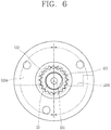
- FIGS. 6 and 7 are a planar view and a longitudinal sectional view, respectively, showing an oil collection pump shown in FIG. 3
- FIG. 8 is a longitudinal sectional view showing another example of the oil collection pump of FIG. 7 .
- the oil collection pump 52 may be implemented by employing various types of pumps. As shown in the exemplary embodiment, the oil collection pump 52 may be implemented as a trochoid gear pump which includes an inner gear 521 and an outer gear 522 engaged with each other to form a variable displacement.
- the inner gear 521 of the oil collection pump 52 may be coupled to the crankshaft 23 to be driven by a driving force of the driving motor 20.
- the inner gear 521 and the outer gear 522 may be received in a pump cover 523 fixed to the sub frame 12.
- the pump cover 523 may include one inlet 5231 and one outlet 5234 which communicate with the variable displacement of the oil collection pump 52, respectively.
- the inlet 5231 may communicate with the oil collection pipe 51 while the outlet 5234 may communicate with an oil storage of the lower space S3 of the shell 10.
- An oil hole 5235 which communicates with the oil passage 231 of the crankshaft 23 may be formed at a central portion of the pump cover 523.
- An oil supply pipe 524 may be coupled to the oil hole 5235 to guide oil stored in the inner space of the shell 10 toward the oil passage 231 of the crankshaft 23.
- the oil supply pipe 524 may be directly coupled to the oil passage 231 of the crankshaft 23 via the oil hole 5235.
- a pumping member 525 such as a propeller, which may generate a pumping force, may be inserted in the oil supply pipe 524, to improve the oil pumping force when the oil supply pipe 524 rotates in response to rotation of the crankshaft 23.
- the oil separator 41 of the scroll compressor having the configuration may separate oil from a refrigerant, which is discharged from the inner space of the shell 10 into the refrigeration cycle, and the separated oil is collected back into the inner space of the shell 10 by the oil collection pump 52.
- oil introduced into the compression chambers P is discharged together with a refrigerant to be introduced into the oil separator 41 via the discharge pipe 14.
- the oil is separated from the refrigerant in the oil separator 41.
- the separated refrigerant flows toward the condenser of the refrigeration cycle via the refrigerant pipe 1, while the separated oil is gathered on a bottom of the oil separator 41.
- the crankshaft 23 of the driving motor 20 rotates, the inner gear 521 of the oil collection pump 52 rotates to generate a pumping force with forming a variable displacement with the outer gear 522.
- the pumping force is used to pump the oil separated by the oil separator 41.
- the oil pumped by the oil collection pump 52 is collected into the lower space S3 of the shell 10, which defines an oil storage, via the oil collection pipe 51 and the oil collection pump 52.
- the oil collected in the inner space of the shell 10 is sucked up via the oil supply pipe 524 and the oil passage 231 of the crankshaft 23, thereby being supplied to a sliding (bearing) portion of the compression unit 30.
- the inner space of the shell 10 which defines a relatively high pressure part may communicate with the compression chamber P which defines a relatively low pressure part, such that the oil collected in the inner space of the shell 10 can be sucked from the inner space of the shell 10 back into the compression chamber P by a pressure difference (differential pressure).
- FIG. 9 is a longitudinal sectional view showing a part of a compression unit for illustrating a differential pressure passage in the scroll compressor of FIG. 3
- FIG. 10 is a planar view showing the compression unit for illustrating positions of the back pressure passage and the differential pressure passage according to the present disclosure.
- a communication hole 316 may be formed at the fixed scroll 31.
- the communication hole 316 may communicate from a thrust bearing surface (hereinafter, referred to as a first thrust surface) 319 contacting the orbiting scroll 32 to the compression chamber P.
- a differential pressure hole 324 may be formed at the orbiting scroll 32.
- the differential pressure hole 324 may guide oil sucked up via the oil passage 231 toward a thrust bearing surface (hereinafter, referred to as a second thrust surface) 329 contacting the fixed scroll 31.
- a thrust bearing surface hereinafter, referred to as a second thrust surface
- the communication hole 316 may include a first open end 3161 contacting the first thrust surface 319 and a second open end 3162 communicating with the first open end 3161 and contacting the compression chamber P.
- the second open end 3162 may preferably be formed at a position closer to the suction groove (or suction chamber) 313 than the second open end 3152 of the back pressure hole 315 based upon the suction groove 313, without being overlapped by the second open end 3152 of the back pressure hole 315.
- an opening time point of the second open end 3162 as an outlet of the communication hole 316 may preferably be within approximately -60°, based on a crank angle, from a suction-completed time point, namely, a time point when an outer surface of an outer end of the orbiting wrap 322 contacts an inner surface of an outer end of the fixing warp 312.
- the second open end 3162 of the communication hole 316 may preferably be formed at a position where it can independently communicate with the both compression chambers P in an alternating manner so as to supply oil into the both compression chambers P.
- the second open end 3162 of the communication hole 316 may preferably be formed such that an inner diameter thereof cannot be greater than a wrap thickness of the orbiting wrap 33 to prevent a leakage of refrigerant between the both compression chambers.
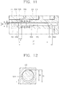
- FIG. 11 is a longitudinal sectional view showing the differential pressure hole of FIG. 9 in an enlarged state
- FIGS. 12 and 13 are sectional views taken along the lines "II-II" and "III-III” of FIG. 11 , respectively.
- the differential pressure hole 324 may penetrate through a center of the disc portion 321 of the orbiting scroll 32 toward an outer circumferential surface in a radial direction.
- the differential pressure hole 324 may include a decompression portion 3241, in which the pin member 325 is slidably inserted in a radial direction to decompress oil pressure.
- An inner diameter D1 of the decompression portion 3241 may preferably be formed slightly greater than an outer diameter D2 of the pin member 325 such that pressure of oil introduced into the decompression portion 3241 can be decompressed while the oil flows between the decompression portion 3241 and the pin member 325.
- An inlet 3242 of the differential pressure hole 324 may be formed at one end portion of the decompression portion 3241 such that oil can be introduced into the decompression portion 3241 therethrough.
- An outlet 3243 of the differential pressure hole 324 may be formed at the other end portion of the decompression portion 3241 such that the oil passing through the decompression portion 3241 can be discharged to the thrust bearing surface 329 between the orbiting scroll 32 and the fixed scroll 31 so as to flow toward the communication hole 316.
- a length L1 between the inlet 3242 and the outlet 3243 of the differential pressure hole 324 may preferably be longer than a length L2 of the pin member 235 such that the pin member 325 can be slidable within the decompression portion 3241.
- the inlet 3241 of the differential pressure hole 324 may preferably be formed such that the oil sucked via the oil passage 231 can be introduced into the inlet 3241 of the differential pressure hole 324 after lubrication between the boss portion 323 of the orbiting scroll 32 and the shaft receiving portion 113 of the main frame 11, deriving a smooth lubrication of the orbiting scroll 32.
- the inlet 3241 of the differential pressure hole 324 may preferably be positioned at outside of an outer circumferential surface of the boss portion 323 based on a center of the boss portion 323, namely, between the shaft receiving portion 113 and the sealing member 114.
- a communication groove 3163 which has a sectional area greater than that of the differential pressure hole 324 or the communication hole 316, may be formed at at least one of the outlet 3242 of the differential pressure hole 324 or the first open end 3161 of the communication hole 316 (the communication groove 3163 is formed at the first open end of the communication hole 316 in the drawing). This may result in an increase in an amount of oil sucked.
- An expansion portion 3244 which has an inner diameter D3 greater than the inner diameter D1 of the decompression portion 3241 for expanding oil passing through the decompression portion 3241, may be formed near the outlet 3243 of the differential pressure hole 324.
- the decompression portion 3241 may preferably communicate with the expansion portion 3244.
- a length L3 of the expansion portion 3244 may preferably be formed shorter than the length L2 of the pin member 325 such that the pin member 325 can be placed over the expansion portion 3244 and the decompression portion 3241.
- the oil stored in the inner space of the shell 10 may be sucked into the compression chamber P as a low pressure part by a pressure difference.
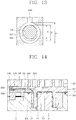
- FIG. 14 is a longitudinal sectional view showing a process of supplying oil via the differential pressure passage of FIG. 9 .
- oil introduced into the boss portion 323 of the orbiting scroll 32 via the oil passage 231 of the crankshaft 23 flows toward an outer circumferential surface of the boss portion 323 and then moves onto a thrust bearing surface between the orbiting scroll 32 and the main frame 11.
- the oil moving to the thrust bearing surface between the main frame 11 and the orbiting scroll 32 is partially introduced into the decompression portion 3241 via the inlet 3242 of the differential pressure hole 324.
- the oil introduced into the decompression portion 3241 flows to the outlet 3243 of the differential pressure hole 324 via a gap (t) (see FIG. 12 ), which is formed between an inner circumferential surface of the decompression portion 3241 and an outer circumferential surface of the pin member 325, or to the expansion portion 3244 when the expansion portion is formed.
- Such oil then flows to the thrust bearing surfaces 319 and 329 between the fixed scroll 31 and the orbiting scroll 32 via the outlet 3243 of the differential pressure hole 324.
- the oil is introduced into the first open end 3161 of the communication hole 316 to be guided into the suction chamber 313 via the second open end 3162 of the communication hole 316.
- the expansion portion may alternatively be formed at the pin member.
- the pin member 325 may be multiply stepped to have a large diameter part 3251 and a small diameter part 3252.
- the small diameter part 3252 may be defined as the expansion portion.
- the operating effect may be the same or similar to the aforementioned embodiment, so description thereof will be omitted.
- the oil collection pump has the one inlet and the one outlet such that the inlet communicates with the oil collection pipe and the outlet communicates with the inner space of the shell, respectively.
- the oil collection pump 52 may include two inlets 5231 and 5232 and one outlet 5234.
- the two inlets 5231 and 5232 of the oil collection pump 52 may communicate with the oil collection pipe 51 and the inner space of the shell 10, respectively, while the one outlet 5234 may communicate directly with the oil passage 231 of the crankshaft 23.
- An oil storage 5236 for storing a predetermined amount oil may further be formed in the outlet 5234. The oil storage 5236 may communicate with the oil passage 231 of the crankshaft 23.
- pressure of the oil passage 231, more particularly, pressure of the oil storage 5236 of the pump cover 523 becomes higher than pressure of the compression chambers P. Accordingly, oil collected via the oil collection pipe 51 and oil pumped up from the inner space of the shell 10 may be sucked into the compression chambers P not only by the differential pressure but also by the pumping force of the oil collection pump 52. This may allow the oil to be smoothly supplied even during a low speed driving and at the begging of the driving.
- the oil collection pump 52 of the oil collecting unit 50 may be installed outside the shell 10 and driven by using a driving source separate from the driving motor 20.
- the oil collection pump 52 may be installed at a middle of the oil collection pipe 51 at outside of the shell 10, and an inverter motor whose rotation speed increases or decreases cooperative with the rotation speed of the driving motor 20 may be installed.
- the outlet of the oil collection pipe 51 may be connected directly to the oil passage 231 of the crankshaft 23, but in some cases, connected to the inner space of the shell 10.
- the basic configuration of pumping oil into the compression chambers and its operating effect are the same or similar to the aforementioned embodiments.
- the pump for pumping oil may be installed outside the shell 10 other than inside the shell 10 and the oil collection pipe 51 communicates with the inner space of the shell 10. Accordingly, foreign materials contained in the oil may be filtered in the inner space of the shell 10. This may prevent contamination of the oil supplied to the thrust surfaces or the compression chambers P in advance. Also, the installation of the oil collection pump 52 at the outside of the shell 10 may facilitate maintenance and management of the oil collection pump 52.
- the present disclosure may be applied equally to a so-called hermetic compressor, such as a rotary compressor and the like, in which a driving motor and a compression unit are installed inside the same shell, without being limited to the scroll compressor.
Description
- This specification relates to a scroll compressor capable of supplying oil within a shell to a compressor using differential pressure.
- A refrigerant compression type refrigeration cycle is configured by connecting a compressor, a condenser, an expansion apparatus and an evaporator via a closed loop refrigerant pipe, and a refrigerant compressed in the compressor circulates sequentially via the condenser, the expansion apparatus and the evaporator.
- When the compressor is installed in the refrigerant compression type refrigeration cycle, a predetermined amount of oil is required for lubrication of a driving unit, sealing of a compression unit, cooling and the like. Hence, the predetermined amount of oil is filled in a shell of the compressor. However, some of the oil is mixed with the refrigerant to be discharged out of the compressor, and the discharged oil circulates via the condenser, the expansion apparatus and the evaporator together with the refrigerant. However, when an excessive amount of oil circulates along the refrigeration cycle or a large amount of oil remains in the refrigeration cycle without being collected back into the compressor, a lack of oil within the compressor is caused. This may result in lowering of reliability of the compressor and accordingly lowering a heat exchange performance of the refrigeration cycle.
- In the related art, a scroll compressor is well known. The scroll compressor includes an oil separator installed at a discharge side of the compressor, an oil pump for collecting oil separated by the oil separator, and an oil collection pipe connecting the oil separator to the oil pump. In the scroll compressor, even if an inner space of the shell is filled with discharge pressure, the oil separated by the oil separator may be smoothly collected. However, as the oil pump is installed at a lower end of a crankshaft of the scroll compressor, a pumping force is not so strong during low speed driving of the compressor. This is likely to cause reliability of the compressor to be lowered.
- A scroll compressor using differential pressure has been introduced as a technology for maintaining a predetermined amount of pumped oil during the low speed driving of the compressor. In the scroll compressor, a differential pressure hole, which communicates the inner space of the shell as a high pressure part with a suction chamber as a low pressure part, is formed at an orbiting scroll. Accordingly, oil is allowed to be fast supplied into the suction chamber by using a pumping force of the oil pump and an attractive force generated due to pressure difference. This allows the oil to be smoothly pumped during the low speed driving, enhancing reliability of the compressor.
- However, in the scroll compressor for supplying oil into a compression chamber using the differential pressure, the smooth supply of the oil into the compressor chamber even during the low speed driving is allowed, but such oil is supplied into the compressor in a high pressure state or more than an appropriate amount oil is supplied into the compression chamber, causing a suction loss.
- Taking it into account, the related art has employed a decompression device in which a
pin member 2 is inserted into adifferential pressure hole 1 to function as a type of orifice. - The
differential pressure hole 1 has an inlet 1a which is formed inside aboss portion 3a of an orbitingscroll 3. Apin supporting portion 1c for supporting thepin member 2 in a lengthwise direction is formed at an inner circumferential surface of thedifferential pressure hole 1 in a stepped state. - In the related art decompression device, the
pin member 2 is placed at a position where it is always overlapped by anoutlet 1b of thedifferential pressure hole 1 due to thepin supporting portion 1c. Thepin member 2 narrows theoutlet 1 b of thedifferential pressure hole 1 due to oil introduced between thepin member 2 and thedifferential pressure hole 1 via the inlet 1a. Accordingly, pressure and an amount of oil supplied into the suction chamber via theoutlet 1 b of thedifferential pressure hole 1 are appropriately adjusted. - However, in the related art scroll compressor, oil pressure and oil amount are adjusted as the pin member blocks a part of the outlet of the differential pressure hole. Thus, in order for the pin member to always block the part of the outlet of the differential pressure hole, the pin supporting portion for limiting the position of the pin member has to be stepped with respect to the differential pressure hole, which makes processing of the orbiting scroll complicated.
- Furthermore, as the inlet of the differential pressure hole is formed inside the boss portion of the orbiting scroll, oil sucked up from the crankshaft is not sufficiently supplied to a thrust bearing surface between the orbiting scroll and a frame. This is likely to cause frictional loss and abrasion of the thrust bearing surface.
-
EP 2 221 479 A2 -
EP 2 020 578 A2 - Therefore, an aspect of the detailed description is to provide a scroll compressor capable of facilitating processing of an orbiting scroll by simplifying a structure of a differential pressure hole for insertion of a pin member therein.
- Another aspect of the detailed description is to provide a scroll compressor capable of reducing frictional loss and abrasion by allowing oil to be sufficiently supplied between an orbiting scroll and a frame.
- To achieve these and other advantages and in accordance with the purpose of this specification, as embodied and broadly described herein, there is provided a scroll compressor including a shell having an inner space filled with refrigerant discharged to the inner space, the inner space containing a predetermined amount of oil, a driving motor installed in the shell, a crankshaft coupled to a rotor of the driving motor and having an oil passage formed therethrough, a fixed scroll fixed to the shell and having a fixing wrap, and an orbiting scroll having an orbiting wrap engaged with the fixing wrap, the orbiting scroll forming compression chambers together with the fixed scroll while orbiting with respect to the fixed scroll, wherein the orbiting scroll may include a differential pressure hole for communicating a high pressure part formed in the inner space of the shell with an intermediate pressure part formed between the fixed scroll and the orbiting scroll, wherein the differential pressure hole may include a decompression portion having a pin member inserted therein for decompressing oil, and an inner diameter D1 of the decompression portion is greater than an outer diameter D2 of the pin member, and wherein the decompression portion may include an inlet through which oil is introduced from a high pressure part into the differential pressure hole, and an outlet through which oil from the differential pressure hole is discharged into an intermediate pressure part, and a length L1 between the inlet and the outlet may be longer than a length L2 of the pin member.
- Further scope of applicability of the present application will become more apparent from the detailed description given hereinafter. However, it should be understood that the detailed description and specific examples, while indicating preferred embodiments of the invention, are given by way of illustration only, since various changes and modifications within the scope of the invention will become apparent to those skilled in the art from the detailed description.
- The accompanying drawings, which are included to provide a further understanding of the invention and are incorporated in and constitute a part of this specification, illustrate exemplary embodiments and together with the description serve to explain the principles of the invention.
- In the drawings:
-
FIG. 1 is a longitudinal sectional view of an oil supplying structure for supplying oil into a compression chamber using differential pressure in a scroll compressor according to the related art; -
FIG. 2 is a sectional view taken along the line "I-I" ofFIG. 1 ; -
FIG. 3 is a longitudinal sectional view showing an internal structure of a scroll compressor in accordance with the present disclosure; -
FIG. 4 is a longitudinal sectional view showing a part of a compression unit for illustrating a back pressure passage in the scroll compressor ofFIG. 3 ; -
FIG. 5 is a schematic view showing a sealing effect between a fixed scroll and an orbiting scroll by the back pressure passage ofFIG. 4 ; -
FIGS. 6 and7 are a planar view and a longitudinal sectional view respectively showing an oil collection pump shown inFIG. 3 ; -
FIG. 8 is a longitudinal sectional view showing another example of the oil collection pump ofFIG. 7 ; -
FIG. 9 is a longitudinal sectional view showing a part of a compression unit for illustrating a differential pressure passage in the scroll compressor ofFIG. 3 ; -
FIG. 10 is a planar view showing the compression unit for illustrating positions of the back pressure passage and the differential pressure passage according to the present disclosure; -
FIG. 11 is a longitudinal sectional view showing the differential pressure hole ofFIG. 9 in an enlarged state; -
FIGS. 12 and13 are sectional views taken along the lines "II-II" and "III-III" ofFIG. 11 , respectively; -
FIG. 14 is a longitudinal sectional view showing a process of supplying oil via the differential pressure passage ofFIG. 9 ; -
FIG. 15 is a longitudinal sectional view showing another example of the differential pressure hole ofFIG 9 in an enlarged state; -
FIG. 16 is a longitudinal sectional view showing another exemplary embodiment of an oil collection pump in accordance with the present disclosure; and -
FIG. 17 is a longitudinal sectional view showing another exemplary embodiment of a scroll compressor having an oil collection pump disposed outside a shell in accordance with the present disclosure. - Description will now be given in detail of a compressor in accordance with the exemplary embodiments, with reference to the accompanying drawings. For the sake of brief description with reference to the drawings, the same or equivalent components will be provided with the same reference numbers, and description thereof will not be repeated.
-
FIG. 3 is a longitudinal sectional view showing an internal structure of a scroll compressor in accordance with the present disclosure, andFIG. 4 is a longitudinal sectional view showing a part of a compression unit for illustrating a back pressure passage in the scroll compressor ofFIG. 3 . - As shown in
FIG. 3 , a scroll compressor according to this specification may include ashell 10 having a sealed inner space, a drivingmotor 20 installed in the inner space of theshell 10, and acompression unit 30 having afixed scroll 31 and aorbiting scroll 32, which are driven by thedriving motor 20 to compress a refrigerant. - The
shell 10 may have an inner space filled with a refrigerant of discharge pressure. Asuction pipe 13 may penetrate through one side of theshell 10 so as to communicate with a suction groove 313 (or suction chamber) of thefixed scroll 31, and adischarge pipe 14 may be connected to another side of theshell 10 to guide a refrigerant discharged into the inner space of theshell 10 toward a refrigeration cycle. - The driving
motor 20 may include astator 21 wound with a winding coil in a concentrated winding manner. The drivingmotor 20 may be implemented as a constant speed motor in which arotor 22 rotates at the same rotation speed. Alternatively, thedriving motor 20 may be implemented as an inverter motor in which the rotation speed of therotor 22 is variable, taking multifunctional refrigerating devices having a compressor into account. Also, thedriving motor 20 may be supported by amain frame 11 and asub frame 12, which are fixed onto both upper and lower sides of theshell 10. - The
compression unit 30 may include afixed scroll 31 coupled to themain frame 11, anorbiting scroll 32 engaged with thefixed scroll 31 to define a pair of compression chambers P which continuously move, an Oldhamring 33 installed between the orbitingscroll 32 and themain frame 11 to induce an orbiting motion of the orbitingscroll 32, and acheck valve 34 installed to open and close thedischarge hole 314 of thefixed scroll 31 so as to block gas discharged via thedischarge hole 314 from back flowing. - The
fixed scroll 31 may include afixing wrap 312 formed at a lower surface of adisc portion 311 for defining the compression chambers P, asuction groove 313 formed at an edge of thelight plate 311, and adischarge hole 314 formed at a central portion of thedisc portion 311. Thesuction pipe 13 may be directly connected to thesuction groove 313 of thefixed scroll 31 so as to guide a refrigerant from a refrigeration cycle. - The orbiting
scroll 32 may include anorbiting wrap 322 formed at an upper surface of adisc portion 321 for defining the compression chambers P by being engaged with the fixingwrap 312, and aboss portion 323 formed at a lower surface of thedisc portion 321 and coupled with acrankshaft 23. Theboss portion 323 may be orbitably inserted into ashaft receiving portion 113, which extends to ashaft receiving hole 111 of themain frame 11 and is formed at a thrust bearing surface 122 to have a preset depth. - A back pressure chamber S1, which is defined as an intermediate pressure space by the orbiting
scroll 32, the fixingscroll 31 and themain frame 11, may be formed at an edge of a rear surface of the orbitingscroll 32. A sealingmember 114 may be installed between themain frame 11 and the orbitingscroll 32 to prevent oil sucked up via anoil passage 231 of thecrankshaft 23 from being excessively introduced into the back pressure chamber S1. The sealingmember 114 may be located between theshaft receiving portion 113 of themain frame 11 and the back pressure chamber S1. - Referring to
FIG. 4 , aback pressure hole 315 may be formed at the fixedscroll 31. Theback pressure hole 315 may serve to induce a part of a refrigerant from an intermediate compression chamber having intermediate pressure between suction pressure and discharge pressure toward the back pressure chamber S1 so as to support an edge of the orbitingscroll 32 in a thrusting direction. Theback pressure hole 315 may include a firstopen end 3151 communicating with the compression chambers P, and a secondopen end 3152 communicating with the firstopen end 3151 and also the back pressure chamber S1. The firstopen end 3151 of theback pressure hole 315 may preferably be located at a position where it can independently communicate with the both compression chambers P in an alternating manner and can be thinner than a wrap thickness of theorbiting wrap 322, preventing a leakage of a refrigerant in the both compression chambers P. - With the configuration of the scroll compressor, when power is applied to the driving
motor 20, thecrankshaft 23 rotates together with therotor 22 to transfer a rotational force to theorbiting scroll 32. Upon reception of the rotation force, the orbitingscroll 32 orbits by an eccentric distance from the upper surface of themain frame 11 by theOldham ring 33. Accordingly, a pair of compression chambers P which continuously move are formed between the fixingwrap 312 of the fixedscroll 31 and the orbiting wrap 322 of the orbitingscroll 32. The compression chambers P are reduced in volume while moving toward a center by the continuous orbiting motion of the orbitingscroll 32, compressing a sucked refrigerant. Here, referring toFIG. 5 , a central portion of the orbitingscroll 32 is supported by oil introduced into theshaft receiving portion 113 while a side portion of the orbitingscroll 32 is supported by a refrigerant introduced from the compression chamber P into the back pressure chamber S1 via theback pressure hole 315. Consequently, the refrigerant within the compression chambers P may be smoothly compressed without being leaked. - The refrigerant compressed in the compression chambers P is continuously discharged into an upper space S2 of the
shell 10 via thedischarge hole 314 of the fixedscroll 31 and then flows into a lower space S3 of theshell 10, thereby being discharged into a refrigeration cycle system via thedischarge pipe 14. Here, anoil separating unit 40 may be installed at a middle of thedischarge pipe 14 to separate oil from the refrigerant, which is discharged from theshell 10 into the refrigeration cycle via thedischarge pipe 14, and anoil collecting unit 50 for collecting the oil separated by theoil separating unit 40 into theshell 10 may be installed on theoil separating unit 40. - The
oil separating unit 40, as shown inFIG. 3 , may include anoil separator 41 disposed at one side of theshell 10 in series, and an oil separation member (not shown) installed in theoil separator 41 to separate oil from a refrigerant discharged from thecompression unit 30. Thedischarge pipe 14 may be connected to a middle of a side wall surface of theoil separator 41 for supporting, or a supportingmember 42 such as a clamp may be disposed between theshell 10 and theoil separator 41 for supporting. Arefrigerant pipe 15 may be connected to an upper end of theoil separator 41 to make the separated refrigerant flowing into a condenser of the refrigeration cycle. Anoil collection pipe 51 to be explained later may be connected to a lower end of theoil separator 41 so as to guide the oil separated by theoil separator 41 to be collected into theshell 10 or thecompression unit 30 of the compressor. - The
oil separating unit 40 may employ various oil separation methods, such as installing a mesh screen in theoil separator 41 to separate oil from a refrigerant or connecting the discharge pipe in an inclined state to separate relatively heavy oil from a refrigerant while the refrigerant rotates in a cyclone shape. - The
oil collecting unit 50 may include anoil collection pipe 51 connected to theoil separator 41 to guide oil separated by theoil separator 41 toward theshell 10, and anoil collection pump 52 connected to theoil collection pipe 51 to pump the oil separated by theoil separator 41 toward theshell 10. - The
oil collection pipe 51 may have one end connected to the lower end of theoil separator 41 and the other end connected to an inlet of theoil collection pipe 51 via theshell 10. Theoil collection pipe 51 may be made of a metal pipe having a predetermined rigidity to stably support theoil separator 41. Also, theoil collection pipe 51 may be curved by an angle at which theoil separator 41 is arranged in parallel to theshell 10 so as to attenuate vibration of the compressor. Theoil collection pipe 51 may be coupled to apump cover 523 of theoil collection pump 52, which will be explained later, using a communication hole (not shown) formed at thesub frame 12. -
FIGS. 6 and7 are a planar view and a longitudinal sectional view, respectively, showing an oil collection pump shown inFIG. 3 , andFIG. 8 is a longitudinal sectional view showing another example of the oil collection pump ofFIG. 7 . - As shown in
FIGS. 6 and7 , theoil collection pump 52 may be implemented by employing various types of pumps. As shown in the exemplary embodiment, theoil collection pump 52 may be implemented as a trochoid gear pump which includes aninner gear 521 and anouter gear 522 engaged with each other to form a variable displacement. - The
inner gear 521 of theoil collection pump 52 may be coupled to thecrankshaft 23 to be driven by a driving force of the drivingmotor 20. Theinner gear 521 and theouter gear 522 may be received in apump cover 523 fixed to thesub frame 12. Thepump cover 523 may include oneinlet 5231 and oneoutlet 5234 which communicate with the variable displacement of theoil collection pump 52, respectively. Theinlet 5231 may communicate with theoil collection pipe 51 while theoutlet 5234 may communicate with an oil storage of the lower space S3 of theshell 10. - An
oil hole 5235 which communicates with theoil passage 231 of thecrankshaft 23 may be formed at a central portion of thepump cover 523. Anoil supply pipe 524 may be coupled to theoil hole 5235 to guide oil stored in the inner space of theshell 10 toward theoil passage 231 of thecrankshaft 23. As an alternative example, as shown inFIG. 8 , theoil supply pipe 524 may be directly coupled to theoil passage 231 of thecrankshaft 23 via theoil hole 5235. When theoil supply pipe 524 is directly coupled to thecrankshaft 23, a pumpingmember 525, such as a propeller, which may generate a pumping force, may be inserted in theoil supply pipe 524, to improve the oil pumping force when theoil supply pipe 524 rotates in response to rotation of thecrankshaft 23. - The
oil separator 41 of the scroll compressor having the configuration may separate oil from a refrigerant, which is discharged from the inner space of theshell 10 into the refrigeration cycle, and the separated oil is collected back into the inner space of theshell 10 by theoil collection pump 52. - In more detail, oil introduced into the compression chambers P is discharged together with a refrigerant to be introduced into the
oil separator 41 via thedischarge pipe 14. The oil is separated from the refrigerant in theoil separator 41. The separated refrigerant flows toward the condenser of the refrigeration cycle via therefrigerant pipe 1, while the separated oil is gathered on a bottom of theoil separator 41. Here, as thecrankshaft 23 of the drivingmotor 20 rotates, theinner gear 521 of theoil collection pump 52 rotates to generate a pumping force with forming a variable displacement with theouter gear 522. The pumping force is used to pump the oil separated by theoil separator 41. The oil pumped by theoil collection pump 52 is collected into the lower space S3 of theshell 10, which defines an oil storage, via theoil collection pipe 51 and theoil collection pump 52. - Here, the oil collected in the inner space of the
shell 10 is sucked up via theoil supply pipe 524 and theoil passage 231 of thecrankshaft 23, thereby being supplied to a sliding (bearing) portion of thecompression unit 30. - In accordance with the present disclosure, the inner space of the
shell 10 which defines a relatively high pressure part may communicate with the compression chamber P which defines a relatively low pressure part, such that the oil collected in the inner space of theshell 10 can be sucked from the inner space of theshell 10 back into the compression chamber P by a pressure difference (differential pressure). -
FIG. 9 is a longitudinal sectional view showing a part of a compression unit for illustrating a differential pressure passage in the scroll compressor ofFIG. 3 , andFIG. 10 is a planar view showing the compression unit for illustrating positions of the back pressure passage and the differential pressure passage according to the present disclosure. As shown inFIGS. 9 and10 , acommunication hole 316 may be formed at the fixedscroll 31. Thecommunication hole 316 may communicate from a thrust bearing surface (hereinafter, referred to as a first thrust surface) 319 contacting the orbitingscroll 32 to the compression chamber P. Adifferential pressure hole 324 may be formed at the orbitingscroll 32. Thedifferential pressure hole 324 may guide oil sucked up via theoil passage 231 toward a thrust bearing surface (hereinafter, referred to as a second thrust surface) 329 contacting the fixedscroll 31. - The
communication hole 316 may include a firstopen end 3161 contacting thefirst thrust surface 319 and a secondopen end 3162 communicating with the firstopen end 3161 and contacting the compression chamber P. The secondopen end 3162, as shown inFIG. 4 , may preferably be formed at a position closer to the suction groove (or suction chamber) 313 than the secondopen end 3152 of theback pressure hole 315 based upon thesuction groove 313, without being overlapped by the secondopen end 3152 of theback pressure hole 315. - Here, when the second
open end 3162 of thecommunication hole 316 is formed too close to a discharge side, it may increase pressure within thecommunication hole 316. This may interrupt smooth oil introduction or cause compression loss. Hence, as shown inFIG. 10 , an opening time point of the secondopen end 3162 as an outlet of thecommunication hole 316 may preferably be within approximately -60°, based on a crank angle, from a suction-completed time point, namely, a time point when an outer surface of an outer end of the orbiting wrap 322 contacts an inner surface of an outer end of the fixingwarp 312. Also, the secondopen end 3162 of thecommunication hole 316 may preferably be formed at a position where it can independently communicate with the both compression chambers P in an alternating manner so as to supply oil into the both compression chambers P. In addition, the secondopen end 3162 of thecommunication hole 316 may preferably be formed such that an inner diameter thereof cannot be greater than a wrap thickness of the orbitingwrap 33 to prevent a leakage of refrigerant between the both compression chambers. -
FIG. 11 is a longitudinal sectional view showing the differential pressure hole ofFIG. 9 in an enlarged state, andFIGS. 12 and13 are sectional views taken along the lines "II-II" and "III-III" ofFIG. 11 , respectively. As shown inFIGS. 11 to 13 , thedifferential pressure hole 324 may penetrate through a center of thedisc portion 321 of the orbitingscroll 32 toward an outer circumferential surface in a radial direction. Thedifferential pressure hole 324 may include adecompression portion 3241, in which thepin member 325 is slidably inserted in a radial direction to decompress oil pressure. - An inner diameter D1 of the
decompression portion 3241 may preferably be formed slightly greater than an outer diameter D2 of thepin member 325 such that pressure of oil introduced into thedecompression portion 3241 can be decompressed while the oil flows between thedecompression portion 3241 and thepin member 325. - An
inlet 3242 of thedifferential pressure hole 324 may be formed at one end portion of thedecompression portion 3241 such that oil can be introduced into thedecompression portion 3241 therethrough. Anoutlet 3243 of thedifferential pressure hole 324 may be formed at the other end portion of thedecompression portion 3241 such that the oil passing through thedecompression portion 3241 can be discharged to thethrust bearing surface 329 between the orbitingscroll 32 and the fixedscroll 31 so as to flow toward thecommunication hole 316. - A length L1 between the
inlet 3242 and theoutlet 3243 of thedifferential pressure hole 324 may preferably be longer than a length L2 of the pin member 235 such that thepin member 325 can be slidable within thedecompression portion 3241. - The
inlet 3241 of thedifferential pressure hole 324 may preferably be formed such that the oil sucked via theoil passage 231 can be introduced into theinlet 3241 of thedifferential pressure hole 324 after lubrication between theboss portion 323 of the orbitingscroll 32 and theshaft receiving portion 113 of themain frame 11, deriving a smooth lubrication of the orbitingscroll 32. To this end, referring toFIG. 10 , theinlet 3241 of thedifferential pressure hole 324 may preferably be positioned at outside of an outer circumferential surface of theboss portion 323 based on a center of theboss portion 323, namely, between theshaft receiving portion 113 and the sealingmember 114. - A
communication groove 3163, which has a sectional area greater than that of thedifferential pressure hole 324 or thecommunication hole 316, may be formed at at least one of theoutlet 3242 of thedifferential pressure hole 324 or the firstopen end 3161 of the communication hole 316 (thecommunication groove 3163 is formed at the first open end of thecommunication hole 316 in the drawing). This may result in an increase in an amount of oil sucked. - An
expansion portion 3244, which has an inner diameter D3 greater than the inner diameter D1 of thedecompression portion 3241 for expanding oil passing through thedecompression portion 3241, may be formed near theoutlet 3243 of thedifferential pressure hole 324. Thedecompression portion 3241 may preferably communicate with theexpansion portion 3244. - A length L3 of the
expansion portion 3244 may preferably be formed shorter than the length L2 of thepin member 325 such that thepin member 325 can be placed over theexpansion portion 3244 and thedecompression portion 3241. - In the scroll compressor having the configuration, the oil stored in the inner space of the
shell 10 may be sucked into the compression chamber P as a low pressure part by a pressure difference. -
FIG. 14 is a longitudinal sectional view showing a process of supplying oil via the differential pressure passage ofFIG. 9 . As shown inFIG. 14 , oil introduced into theboss portion 323 of the orbitingscroll 32 via theoil passage 231 of thecrankshaft 23 flows toward an outer circumferential surface of theboss portion 323 and then moves onto a thrust bearing surface between the orbitingscroll 32 and themain frame 11. - The oil moving to the thrust bearing surface between the
main frame 11 and the orbitingscroll 32 is partially introduced into thedecompression portion 3241 via theinlet 3242 of thedifferential pressure hole 324. - The oil introduced into the
decompression portion 3241 flows to theoutlet 3243 of thedifferential pressure hole 324 via a gap (t) (seeFIG. 12 ), which is formed between an inner circumferential surface of thedecompression portion 3241 and an outer circumferential surface of thepin member 325, or to theexpansion portion 3244 when the expansion portion is formed. Such oil then flows to thethrust bearing surfaces scroll 31 and the orbitingscroll 32 via theoutlet 3243 of thedifferential pressure hole 324. - Afterwards, the oil is introduced into the first
open end 3161 of thecommunication hole 316 to be guided into thesuction chamber 313 via the secondopen end 3162 of thecommunication hole 316. - Meanwhile, the expansion portion may alternatively be formed at the pin member. For example, as shown in
FIG. 15 , with maintaining the same inner diameter D1 of thedecompression portion 3241, thepin member 325 may be multiply stepped to have alarge diameter part 3251 and asmall diameter part 3252. Of them, thesmall diameter part 3252 may be defined as the expansion portion. - When the expansion portion is formed at the pin member, the operating effect may be the same or similar to the aforementioned embodiment, so description thereof will be omitted.
- Hereinafter, description will be given of another exemplary embodiment of an oil supply apparatus for a scroll compressor according to the present disclosure.
- That is, in the aforementioned embodiment, the oil collection pump has the one inlet and the one outlet such that the inlet communicates with the oil collection pipe and the outlet communicates with the inner space of the shell, respectively. However, in this exemplary embodiment, the
oil collection pump 52, as shown inFIG. 16 , may include twoinlets outlet 5234. - In this structure, the two
inlets oil collection pump 52 may communicate with theoil collection pipe 51 and the inner space of theshell 10, respectively, while the oneoutlet 5234 may communicate directly with theoil passage 231 of thecrankshaft 23. Anoil storage 5236 for storing a predetermined amount oil may further be formed in theoutlet 5234. Theoil storage 5236 may communicate with theoil passage 231 of thecrankshaft 23. - Even in the scroll compressor having the configuration, pressure of the
oil passage 231, more particularly, pressure of theoil storage 5236 of thepump cover 523 becomes higher than pressure of the compression chambers P. Accordingly, oil collected via theoil collection pipe 51 and oil pumped up from the inner space of theshell 10 may be sucked into the compression chambers P not only by the differential pressure but also by the pumping force of theoil collection pump 52. This may allow the oil to be smoothly supplied even during a low speed driving and at the begging of the driving. - Hereinafter, description will be given of another exemplary embodiment of an oil supply apparatus for a scroll compressor according to the present disclosure.
- That is, the aforementioned embodiments have illustrated that the oil collection pump is installed inside the shell or coupled to the driving motor to use the driving force of the driving motor. However, in this exemplary embodiment, as shown in
FIG. 17 , theoil collection pump 52 of theoil collecting unit 50 may be installed outside theshell 10 and driven by using a driving source separate from the drivingmotor 20. To this end, theoil collection pump 52 may be installed at a middle of theoil collection pipe 51 at outside of theshell 10, and an inverter motor whose rotation speed increases or decreases cooperative with the rotation speed of the drivingmotor 20 may be installed. The outlet of theoil collection pipe 51 may be connected directly to theoil passage 231 of thecrankshaft 23, but in some cases, connected to the inner space of theshell 10. - In the scroll compressor having the configuration, the basic configuration of pumping oil into the compression chambers and its operating effect are the same or similar to the aforementioned embodiments. Here, in the scroll compressor according to this another embodiment, the pump for pumping oil may be installed outside the
shell 10 other than inside theshell 10 and theoil collection pipe 51 communicates with the inner space of theshell 10. Accordingly, foreign materials contained in the oil may be filtered in the inner space of theshell 10. This may prevent contamination of the oil supplied to the thrust surfaces or the compression chambers P in advance. Also, the installation of theoil collection pump 52 at the outside of theshell 10 may facilitate maintenance and management of theoil collection pump 52. - The foregoing embodiments have exemplarily illustrated the scroll compressor. However, the present disclosure may be applied equally to a so-called hermetic compressor, such as a rotary compressor and the like, in which a driving motor and a compression unit are installed inside the same shell, without being limited to the scroll compressor.
- The foregoing embodiments and advantages are merely exemplary and are not to be construed as limiting the present disclosure. The present teachings can be readily applied to other types of apparatuses. This description is intended to be illustrative, and not to limit the scope of the claims. Many alternatives, modifications, and variations will be apparent to those skilled in the art. The features, structures, methods, and other characteristics of the exemplary embodiments described herein may be combined in various ways to obtain additional and/or alternative exemplary embodiments.
- As the present features may be embodied in several forms without departing from the characteristics thereof, it should also be understood that the above-described embodiments are not limited by any of the details of the foregoing description, unless otherwise specified, but rather should be construed broadly within its scope as defined in the appended claims, and therefore all changes and modifications that fall within the metes and bounds of the claims, or equivalents of such metes and bounds are therefore intended to be embraced by the appended claims.
Claims (15)
- A scroll compressor comprising:a shell (10) having an inner space filled with refrigerant discharged to the inner space, the inner space containing a predetermined amount of oil;a driving motor (20) installed in the shell;a crankshaft (23) coupled to a rotor (22) of the driving motor and having an oil passage (231) formed therethrough;a fixed scroll (31) fixed to the shell and having a fixing wrap (312); andan orbiting scroll (32) having an orbiting wrap (322) engaged with the fixing wrap, the orbiting scroll (32) forming compression chambers (P) together with the fixed scroll (31) while orbiting with respect to the fixed scroll (31),wherein the orbiting scroll (32) comprises a differential pressure hole (324) for communicating a high pressure part formed in the inner space of the shell with an intermediate pressure part formed between the fixed scroll (31) and the orbiting scroll (32),
wherein the differential pressure hole (324) comprises a decompression portion (3241) having a pin member (325) inserted therein for decompressing oil, and an inner diameter (D1) of the decompression portion (3241) being greater than an outer diameter (D2) of the pin member (325), and
wherein the decompression portion (3241) has an inlet (3242) communicating with the high pressure part and an outlet (3243) communicating with the intermediate pressure part, and a length (L1) between the inlet and the outlet being longer than a length (L2) of the pin member (325),
characterized in that
the fixed scroll (31) comprises a communication hole (316) having a first open end (3161) communicating with the high pressure part, and a second open end (3162) communicating with the first open end and a low pressure part between the fixed scroll (31) and the orbiting scroll (32). - The compressor of claim 1, wherein an expansion portion (3244) having an expanded inner diameter (D3) is formed at the outlet of the differential pressure hole (324), in sequence of the decompression portion (3241).
- The compressor of claim 2, wherein a length (L3) of the expansion portion (3244) is shorter than the length (L2) of the pin member (325).
- The compressor of any of claims 1 to 3, wherein the pin member (325) is multiply stepped to have a large diameter part (3251) and a small diameter part (3252), and the small diameter part (3252) is formed at an end portion of the pin member (325), the end portion corresponding to the outlet of the differential pressure hole (324).
- The compressor of any of claims 1 to 4,
wherein the second open end of the communication hole (316) is open in the range of 0 to -60° of a crank angle based on the suction-completed time point when a suction side end of the orbiting wrap (322) contacts a side surface of the fixing wrap (312). - The compressor of any of claims 1 to 5, wherein the orbiting scroll (32) has a boss portion (323) coupled with the crankshaft (23), and the first open end of the communication hole (316) is located at outside of the boss portion (323) in a radial direction based on a center of the boss portion (323).
- The compressor of any of claims 1 to 6, wherein the orbiting scroll (32) is supported at a thrust bearing surface of a frame (11) fixed to the shell in a thrusting direction, the frame has a shaft receiving portion (113) in which the boss portion (323) is orbitably inserted, and a sealing member (114) is disposed between a thrust bearing surface of the frame (11) and a thrust bearing surface of the orbiting scroll (32) contacting the frame, and
wherein the first open end of the communication hole (316) is located between the shaft receiving portion (113) and the sealing member (114). - The compressor of claim 7, wherein a back pressure chamber (S1) is formed at outside of the sealing member (114), and
wherein the fixed scroll (31) comprises a back pressure hole (315) having one end communicating with the back pressure chamber (S1) and the other end communicating with the compression chambers (P). - The compressor of claim 8, wherein the back pressure hole (315) is formed at a position farther from a suction side than the communication hole (316) based on a movement path of the compression chambers.
- The compressor of any of claims 1 to 9, further comprising an oil separator (41) configured to separate oil from a refrigerant discharged from the compression chambers (P).
- The compressor of claim 10, wherein the oil separator (41) is installed to communicate with a middle of a discharge pipe (14) at the outside of the shell (10), and is configured to communicate with the inner space of the shell (10) via an oil collection pipe (51).
- The compressor of claim 11, wherein the crankshaft (23) comprises an oil pump (52) driven by a rotational force of the crankshaft (23) and pumping the oil separated by the oil separator (41) into the inner space of the shell (10), and
wherein the oil collection pipe (51) is connected to an inlet of the oil pump (52). - The compressor of claim 12, wherein the oil pump (52) comprises one inlet (5231) and one outlet (5234), and
wherein the inlet of the oil pump (52) is configured to communicate with the oil collection pipe (51), and the outlet of the oil pump is configured to communicate with the inner space of the shell (10). - The compressor of claim 12, wherein the oil pump (52) comprises a plurality of inlets (5231) and (5232) and one outlet (5234),
wherein one of the plurality of inlets (5231, 5232) is configured to communicate with the oil collection pipe (51) and the other inlet (5231, 5232) thereof is configured to communicate with the inner space of the shell (10), and
wherein the outlet (5234) of the oil pump (52) is configured to communicate with the oil passage of the crankshaft (23). - The compressor of any of claims 11 to 14, wherein an oil pump (40) for pumping the oil separated by the oil separator (41) into the inner space of the shell (10) is formed at a middle of the oil collection pipe (51).
Applications Claiming Priority (1)
| Application Number | Priority Date | Filing Date | Title |
|---|---|---|---|
| KR20110098596A KR101480472B1 (en) | 2011-09-28 | 2011-09-28 | Scroll compressor |
Publications (3)
| Publication Number | Publication Date |
|---|---|
| EP2574791A2 EP2574791A2 (en) | 2013-04-03 |
| EP2574791A3 EP2574791A3 (en) | 2016-06-22 |
| EP2574791B1 true EP2574791B1 (en) | 2017-03-01 |
Family
ID=47137509
Family Applications (1)
| Application Number | Title | Priority Date | Filing Date |
|---|---|---|---|
| EP12185336.0A Active EP2574791B1 (en) | 2011-09-28 | 2012-09-21 | Scroll compressor |
Country Status (4)
| Country | Link |
|---|---|
| US (1) | US8992191B2 (en) |
| EP (1) | EP2574791B1 (en) |
| KR (1) | KR101480472B1 (en) |
| CN (1) | CN103032329B (en) |
Families Citing this family (31)
| Publication number | Priority date | Publication date | Assignee | Title |
|---|---|---|---|---|
| JP4992948B2 (en) * | 2009-09-18 | 2012-08-08 | ダイキン工業株式会社 | Scroll compressor |
| CN104295498B (en) | 2013-06-27 | 2017-04-12 | 艾默生环境优化技术有限公司 | Compressor |
| JP6329411B2 (en) * | 2014-03-25 | 2018-05-23 | Ntn株式会社 | Internal gear pump |
| JP6393116B2 (en) * | 2014-08-28 | 2018-09-19 | サンデンホールディングス株式会社 | Scroll type fluid machinery |
| US10641269B2 (en) | 2015-04-30 | 2020-05-05 | Emerson Climate Technologies (Suzhou) Co., Ltd. | Lubrication of scroll compressor |
| WO2017124964A1 (en) * | 2016-01-18 | 2017-07-27 | 广东美的暖通设备有限公司 | Method for reducing back pressure fluctuation of scroll compressor, and scroll compressor |
| KR102481368B1 (en) | 2016-04-26 | 2022-12-26 | 엘지전자 주식회사 | Scroll compressor |
| DE102016113057B4 (en) | 2016-07-15 | 2019-05-23 | Hanon Systems | Apparatus for compressing a gaseous fluid having an arrangement for separating a control mass flow and methods for separating the control mass flow |
| KR101828957B1 (en) * | 2016-09-06 | 2018-02-13 | 엘지전자 주식회사 | Scroll compressor |
| CN106286294B (en) * | 2016-09-19 | 2019-06-07 | 珠海格力电器股份有限公司 | Screw compressor |
| KR102506914B1 (en) * | 2016-09-20 | 2023-03-06 | 엘지전자 주식회사 | A co-rotating scroll compressor having back pressure structure |
| CN106801663B (en) * | 2017-02-22 | 2019-01-08 | 北京汽车股份有限公司 | inflator pump for vehicle |
| KR20180136282A (en) | 2017-06-14 | 2018-12-24 | 엘지전자 주식회사 | Compressor having centrifugation and differential pressure structure for oil supplying |
| KR101974272B1 (en) | 2017-06-21 | 2019-04-30 | 엘지전자 주식회사 | Compressor having merged flow path structure |
| KR102396559B1 (en) | 2017-06-22 | 2022-05-10 | 엘지전자 주식회사 | Compressor having lubrication structure for thrust surface |
| KR102440273B1 (en) | 2017-06-23 | 2022-09-02 | 엘지전자 주식회사 | Compressor having enhanced discharge structure |
| KR102409675B1 (en) | 2017-07-10 | 2022-06-15 | 엘지전자 주식회사 | Compressor having enhanced discharge structure |
| KR102383135B1 (en) | 2017-07-24 | 2022-04-04 | 엘지전자 주식회사 | Compressor having centrifugation structure for supplying oil |
| KR101983051B1 (en) * | 2018-01-04 | 2019-05-29 | 엘지전자 주식회사 | Motor operated compressor |
| KR101983052B1 (en) * | 2018-01-04 | 2019-05-29 | 엘지전자 주식회사 | Motor operated compressor |
| US11236648B2 (en) | 2018-11-20 | 2022-02-01 | Emerson Climate Technologies, Inc. | Climate-control system having oil cooling control system |
| KR102553485B1 (en) * | 2018-12-06 | 2023-07-10 | 삼성전자주식회사 | High-pressure type scroll compressor |
| CN110159528B (en) * | 2019-05-23 | 2020-11-17 | 浙江大学 | Two side double flute parallel do not have oily vortex air compressor machine |
| KR102318551B1 (en) | 2020-04-20 | 2021-10-28 | 엘지전자 주식회사 | A compressor |
| KR102448868B1 (en) * | 2020-04-20 | 2022-09-30 | 엘지전자 주식회사 | A compressor |
| KR102340237B1 (en) | 2020-04-21 | 2021-12-16 | 엘지전자 주식회사 | A compressor |
| US11566624B2 (en) | 2020-10-21 | 2023-01-31 | Emerson Climate Technologies, Inc. | Compressor having lubrication system |
| KR102512409B1 (en) * | 2021-02-15 | 2023-03-21 | 엘지전자 주식회사 | Scroll compressor |
| FR3120661B1 (en) | 2021-03-10 | 2023-03-10 | Danfoss Commercial Compressors | Scroll compressor having a centrifugal oil pump |
| FR3120662B1 (en) * | 2021-03-10 | 2023-03-03 | Danfoss Commercial Compressors | Scroll compressor with hydrostatic lower bearing arrangement |
| KR20230083389A (en) * | 2021-12-02 | 2023-06-12 | 엘지전자 주식회사 | Scroll Compressor |
Family Cites Families (11)
| Publication number | Priority date | Publication date | Assignee | Title |
|---|---|---|---|---|
| JPH09151866A (en) * | 1995-11-30 | 1997-06-10 | Sanyo Electric Co Ltd | Scroll compressor |
| JP3731069B2 (en) * | 2002-07-29 | 2006-01-05 | ダイキン工業株式会社 | Compressor |
| JP2005240693A (en) | 2004-02-26 | 2005-09-08 | Mitsubishi Heavy Ind Ltd | Device for adjusting fluid flow rate and scroll compressor |
| JP4754847B2 (en) | 2005-02-28 | 2011-08-24 | 三菱重工業株式会社 | Compressor |
| JP5107817B2 (en) * | 2007-07-30 | 2012-12-26 | エルジー エレクトロニクス インコーポレイティド | Hermetic compressor and refrigeration cycle apparatus using the same |
| CN101358597B (en) * | 2007-07-30 | 2012-07-04 | Lg电子株式会社 | Compressor |
| KR101487822B1 (en) * | 2008-11-14 | 2015-01-29 | 엘지전자 주식회사 | Hermetric compressor and refrigeration cycle device having the same |
| JP2010190167A (en) * | 2009-02-20 | 2010-09-02 | Sanyo Electric Co Ltd | Scroll compressor |
| JP5261227B2 (en) * | 2009-02-20 | 2013-08-14 | 三洋電機株式会社 | Scroll compressor |
| JP5178668B2 (en) * | 2009-09-11 | 2013-04-10 | 日立アプライアンス株式会社 | Scroll compressor |
| JP4879311B2 (en) * | 2009-11-16 | 2012-02-22 | 三菱電機株式会社 | Scroll compressor |
-
2011
- 2011-09-28 KR KR20110098596A patent/KR101480472B1/en active IP Right Grant
-
2012
- 2012-09-21 EP EP12185336.0A patent/EP2574791B1/en active Active
- 2012-09-25 CN CN201210360962.9A patent/CN103032329B/en active Active
- 2012-09-26 US US13/627,064 patent/US8992191B2/en active Active
Non-Patent Citations (1)
| Title |
|---|
| None * |
Also Published As
| Publication number | Publication date |
|---|---|
| US8992191B2 (en) | 2015-03-31 |
| CN103032329A (en) | 2013-04-10 |
| KR20130034536A (en) | 2013-04-05 |
| KR101480472B1 (en) | 2015-01-09 |
| EP2574791A2 (en) | 2013-04-03 |
| CN103032329B (en) | 2016-01-20 |
| US20130078131A1 (en) | 2013-03-28 |
| EP2574791A3 (en) | 2016-06-22 |
Similar Documents
| Publication | Publication Date | Title |
|---|---|---|
| EP2574791B1 (en) | Scroll compressor | |
| EP2689137B1 (en) | Scroll compressor | |
| US8408024B2 (en) | Fluid machine and refrigeration cycle apparatus | |
| EP2020578B1 (en) | Hermetic compressor and refrigeration cycle device having the same | |
| KR102243681B1 (en) | Scroll Compressor | |
| EP2187059B1 (en) | Hermetic compressor and refrigeration cycle device having the same | |
| EP2243958A2 (en) | Compressor and refrigerating apparatus having the same | |
| US20080175738A1 (en) | Compressor and oil blocking device therefor | |
| US8517702B2 (en) | Rotary compressor with enhanced sealing between mode switching device and chamber thereof | |
| EP2187060B1 (en) | Hermetic compressor and refrigeration cycle device having the same | |
| EP2020577B1 (en) | Compressor | |
| KR101964962B1 (en) | Compressor having a structure for preventing reverse flow of refrigerant | |
| EP2990649B1 (en) | Multi-cylinder rotary compressor and vapor compression refrigeration cycle device provided with multi-cylinder rotary compressor | |
| US8734142B2 (en) | Rotation preventing member of a scroll compressor | |
| US9435337B2 (en) | Scroll compressor | |
| KR102379939B1 (en) | Scroll compressor | |
| KR101451663B1 (en) | Hermetric compressor and refrigeration cycle device having the same | |
| US11603840B2 (en) | Scroll compressor having compression chamber oil supplies having stages in which oil supply overlaps and stages in which oil supply does not overlap | |
| KR20100046596A (en) | Hermetric compressor and refrigeration cycle device having the same |
Legal Events
| Date | Code | Title | Description |
|---|---|---|---|
| PUAI | Public reference made under article 153(3) epc to a published international application that has entered the european phase |
Free format text: ORIGINAL CODE: 0009012 |
|
| 17P | Request for examination filed |
Effective date: 20121017 |
|
| AK | Designated contracting states |
Kind code of ref document: A2 Designated state(s): AL AT BE BG CH CY CZ DE DK EE ES FI FR GB GR HR HU IE IS IT LI LT LU LV MC MK MT NL NO PL PT RO RS SE SI SK SM TR |
|
| AX | Request for extension of the european patent |
Extension state: BA ME |
|
| PUAL | Search report despatched |
Free format text: ORIGINAL CODE: 0009013 |
|
| AK | Designated contracting states |
Kind code of ref document: A3 Designated state(s): AL AT BE BG CH CY CZ DE DK EE ES FI FR GB GR HR HU IE IS IT LI LT LU LV MC MK MT NL NO PL PT RO RS SE SI SK SM TR |
|
| AX | Request for extension of the european patent |
Extension state: BA ME |
|
| RIC1 | Information provided on ipc code assigned before grant |
Ipc: F04C 29/02 20060101ALI20160513BHEP Ipc: F04C 18/02 20060101AFI20160513BHEP Ipc: F04C 23/00 20060101ALI20160513BHEP |
|
| RBV | Designated contracting states (corrected) |
Designated state(s): AL AT BE BG CH CY CZ DE DK EE ES FI FR GB GR HR HU IE IS IT LI LT LU LV MC MK MT NL NO PL PT RO RS SE SI SK SM TR |
|
| GRAP | Despatch of communication of intention to grant a patent |
Free format text: ORIGINAL CODE: EPIDOSNIGR1 |
|
| INTG | Intention to grant announced |
Effective date: 20160929 |
|
| STAA | Information on the status of an ep patent application or granted ep patent |
Free format text: STATUS: GRANT OF PATENT IS INTENDED |
|
| GRAS | Grant fee paid |
Free format text: ORIGINAL CODE: EPIDOSNIGR3 |
|
| GRAA | (expected) grant |
Free format text: ORIGINAL CODE: 0009210 |
|
| STAA | Information on the status of an ep patent application or granted ep patent |
Free format text: STATUS: THE PATENT HAS BEEN GRANTED |
|
| RAP1 | Party data changed (applicant data changed or rights of an application transferred) |
Owner name: LG ELECTRONICS INC. |
|
| AK | Designated contracting states |
Kind code of ref document: B1 Designated state(s): AL AT BE BG CH CY CZ DE DK EE ES FI FR GB GR HR HU IE IS IT LI LT LU LV MC MK MT NL NO PL PT RO RS SE SI SK SM TR |
|
| REG | Reference to a national code |
Ref country code: GB Ref legal event code: FG4D |
|
| REG | Reference to a national code |
Ref country code: CH Ref legal event code: EP Ref country code: AT Ref legal event code: REF Ref document number: 871710 Country of ref document: AT Kind code of ref document: T Effective date: 20170315 |
|
| REG | Reference to a national code |
Ref country code: IE Ref legal event code: FG4D |
|
| REG | Reference to a national code |
Ref country code: DE Ref legal event code: R096 Ref document number: 602012029148 Country of ref document: DE |
|
| REG | Reference to a national code |
Ref country code: NL Ref legal event code: MP Effective date: 20170301 |
|
| REG | Reference to a national code |
Ref country code: LT Ref legal event code: MG4D |
|
| REG | Reference to a national code |
Ref country code: AT Ref legal event code: MK05 Ref document number: 871710 Country of ref document: AT Kind code of ref document: T Effective date: 20170301 |
|
| PG25 | Lapsed in a contracting state [announced via postgrant information from national office to epo] |
Ref country code: LT Free format text: LAPSE BECAUSE OF FAILURE TO SUBMIT A TRANSLATION OF THE DESCRIPTION OR TO PAY THE FEE WITHIN THE PRESCRIBED TIME-LIMIT Effective date: 20170301 Ref country code: HR Free format text: LAPSE BECAUSE OF FAILURE TO SUBMIT A TRANSLATION OF THE DESCRIPTION OR TO PAY THE FEE WITHIN THE PRESCRIBED TIME-LIMIT Effective date: 20170301 Ref country code: GR Free format text: LAPSE BECAUSE OF FAILURE TO SUBMIT A TRANSLATION OF THE DESCRIPTION OR TO PAY THE FEE WITHIN THE PRESCRIBED TIME-LIMIT Effective date: 20170602 Ref country code: FI Free format text: LAPSE BECAUSE OF FAILURE TO SUBMIT A TRANSLATION OF THE DESCRIPTION OR TO PAY THE FEE WITHIN THE PRESCRIBED TIME-LIMIT Effective date: 20170301 Ref country code: NO Free format text: LAPSE BECAUSE OF FAILURE TO SUBMIT A TRANSLATION OF THE DESCRIPTION OR TO PAY THE FEE WITHIN THE PRESCRIBED TIME-LIMIT Effective date: 20170601 |
|
| REG | Reference to a national code |
Ref country code: FR Ref legal event code: PLFP Year of fee payment: 6 |
|
| PG25 | Lapsed in a contracting state [announced via postgrant information from national office to epo] |
Ref country code: RS Free format text: LAPSE BECAUSE OF FAILURE TO SUBMIT A TRANSLATION OF THE DESCRIPTION OR TO PAY THE FEE WITHIN THE PRESCRIBED TIME-LIMIT Effective date: 20170301 Ref country code: AT Free format text: LAPSE BECAUSE OF FAILURE TO SUBMIT A TRANSLATION OF THE DESCRIPTION OR TO PAY THE FEE WITHIN THE PRESCRIBED TIME-LIMIT Effective date: 20170301 Ref country code: SE Free format text: LAPSE BECAUSE OF FAILURE TO SUBMIT A TRANSLATION OF THE DESCRIPTION OR TO PAY THE FEE WITHIN THE PRESCRIBED TIME-LIMIT Effective date: 20170301 Ref country code: LV Free format text: LAPSE BECAUSE OF FAILURE TO SUBMIT A TRANSLATION OF THE DESCRIPTION OR TO PAY THE FEE WITHIN THE PRESCRIBED TIME-LIMIT Effective date: 20170301 Ref country code: BG Free format text: LAPSE BECAUSE OF FAILURE TO SUBMIT A TRANSLATION OF THE DESCRIPTION OR TO PAY THE FEE WITHIN THE PRESCRIBED TIME-LIMIT Effective date: 20170601 Ref country code: ES Free format text: LAPSE BECAUSE OF FAILURE TO SUBMIT A TRANSLATION OF THE DESCRIPTION OR TO PAY THE FEE WITHIN THE PRESCRIBED TIME-LIMIT Effective date: 20170301 |
|
| PG25 | Lapsed in a contracting state [announced via postgrant information from national office to epo] |
Ref country code: NL Free format text: LAPSE BECAUSE OF FAILURE TO SUBMIT A TRANSLATION OF THE DESCRIPTION OR TO PAY THE FEE WITHIN THE PRESCRIBED TIME-LIMIT Effective date: 20170301 |
|
| PG25 | Lapsed in a contracting state [announced via postgrant information from national office to epo] |
Ref country code: EE Free format text: LAPSE BECAUSE OF FAILURE TO SUBMIT A TRANSLATION OF THE DESCRIPTION OR TO PAY THE FEE WITHIN THE PRESCRIBED TIME-LIMIT Effective date: 20170301 Ref country code: SK Free format text: LAPSE BECAUSE OF FAILURE TO SUBMIT A TRANSLATION OF THE DESCRIPTION OR TO PAY THE FEE WITHIN THE PRESCRIBED TIME-LIMIT Effective date: 20170301 Ref country code: RO Free format text: LAPSE BECAUSE OF FAILURE TO SUBMIT A TRANSLATION OF THE DESCRIPTION OR TO PAY THE FEE WITHIN THE PRESCRIBED TIME-LIMIT Effective date: 20170301 Ref country code: CZ Free format text: LAPSE BECAUSE OF FAILURE TO SUBMIT A TRANSLATION OF THE DESCRIPTION OR TO PAY THE FEE WITHIN THE PRESCRIBED TIME-LIMIT Effective date: 20170301 Ref country code: IT Free format text: LAPSE BECAUSE OF FAILURE TO SUBMIT A TRANSLATION OF THE DESCRIPTION OR TO PAY THE FEE WITHIN THE PRESCRIBED TIME-LIMIT Effective date: 20170301 |
|
| PGFP | Annual fee paid to national office [announced via postgrant information from national office to epo] |
Ref country code: GB Payment date: 20170810 Year of fee payment: 6 |
|
| PG25 | Lapsed in a contracting state [announced via postgrant information from national office to epo] |
Ref country code: PL Free format text: LAPSE BECAUSE OF FAILURE TO SUBMIT A TRANSLATION OF THE DESCRIPTION OR TO PAY THE FEE WITHIN THE PRESCRIBED TIME-LIMIT Effective date: 20170301 Ref country code: IS Free format text: LAPSE BECAUSE OF FAILURE TO SUBMIT A TRANSLATION OF THE DESCRIPTION OR TO PAY THE FEE WITHIN THE PRESCRIBED TIME-LIMIT Effective date: 20170701 Ref country code: PT Free format text: LAPSE BECAUSE OF FAILURE TO SUBMIT A TRANSLATION OF THE DESCRIPTION OR TO PAY THE FEE WITHIN THE PRESCRIBED TIME-LIMIT Effective date: 20170703 Ref country code: SM Free format text: LAPSE BECAUSE OF FAILURE TO SUBMIT A TRANSLATION OF THE DESCRIPTION OR TO PAY THE FEE WITHIN THE PRESCRIBED TIME-LIMIT Effective date: 20170301 |
|
| REG | Reference to a national code |
Ref country code: DE Ref legal event code: R097 Ref document number: 602012029148 Country of ref document: DE |
|
| PLBE | No opposition filed within time limit |
Free format text: ORIGINAL CODE: 0009261 |
|
| STAA | Information on the status of an ep patent application or granted ep patent |
Free format text: STATUS: NO OPPOSITION FILED WITHIN TIME LIMIT |
|
| PG25 | Lapsed in a contracting state [announced via postgrant information from national office to epo] |
Ref country code: DK Free format text: LAPSE BECAUSE OF FAILURE TO SUBMIT A TRANSLATION OF THE DESCRIPTION OR TO PAY THE FEE WITHIN THE PRESCRIBED TIME-LIMIT Effective date: 20170301 |
|
| 26N | No opposition filed |
Effective date: 20171204 |
|
| PG25 | Lapsed in a contracting state [announced via postgrant information from national office to epo] |
Ref country code: SI Free format text: LAPSE BECAUSE OF FAILURE TO SUBMIT A TRANSLATION OF THE DESCRIPTION OR TO PAY THE FEE WITHIN THE PRESCRIBED TIME-LIMIT Effective date: 20170301 |
|
| REG | Reference to a national code |
Ref country code: CH Ref legal event code: PL |
|
| PG25 | Lapsed in a contracting state [announced via postgrant information from national office to epo] |
Ref country code: MC Free format text: LAPSE BECAUSE OF FAILURE TO SUBMIT A TRANSLATION OF THE DESCRIPTION OR TO PAY THE FEE WITHIN THE PRESCRIBED TIME-LIMIT Effective date: 20170301 |
|
| REG | Reference to a national code |
Ref country code: IE Ref legal event code: MM4A |
|
| REG | Reference to a national code |
Ref country code: BE Ref legal event code: MM Effective date: 20170930 |
|
| PG25 | Lapsed in a contracting state [announced via postgrant information from national office to epo] |
Ref country code: LU Free format text: LAPSE BECAUSE OF NON-PAYMENT OF DUE FEES Effective date: 20170921 |
|
| PG25 | Lapsed in a contracting state [announced via postgrant information from national office to epo] |
Ref country code: LI Free format text: LAPSE BECAUSE OF NON-PAYMENT OF DUE FEES Effective date: 20170930 Ref country code: IE Free format text: LAPSE BECAUSE OF NON-PAYMENT OF DUE FEES Effective date: 20170921 Ref country code: CH Free format text: LAPSE BECAUSE OF NON-PAYMENT OF DUE FEES Effective date: 20170930 |
|
| REG | Reference to a national code |
Ref country code: FR Ref legal event code: PLFP Year of fee payment: 7 |
|
| PG25 | Lapsed in a contracting state [announced via postgrant information from national office to epo] |
Ref country code: BE Free format text: LAPSE BECAUSE OF NON-PAYMENT OF DUE FEES Effective date: 20170930 |
|
| PG25 | Lapsed in a contracting state [announced via postgrant information from national office to epo] |
Ref country code: MT Free format text: LAPSE BECAUSE OF NON-PAYMENT OF DUE FEES Effective date: 20170921 |
|
| GBPC | Gb: european patent ceased through non-payment of renewal fee |
Effective date: 20180921 |
|
| PG25 | Lapsed in a contracting state [announced via postgrant information from national office to epo] |
Ref country code: HU Free format text: LAPSE BECAUSE OF FAILURE TO SUBMIT A TRANSLATION OF THE DESCRIPTION OR TO PAY THE FEE WITHIN THE PRESCRIBED TIME-LIMIT; INVALID AB INITIO Effective date: 20120921 |
|
| PG25 | Lapsed in a contracting state [announced via postgrant information from national office to epo] |
Ref country code: CY Free format text: LAPSE BECAUSE OF NON-PAYMENT OF DUE FEES Effective date: 20170301 Ref country code: GB Free format text: LAPSE BECAUSE OF NON-PAYMENT OF DUE FEES Effective date: 20180921 |
|
| PG25 | Lapsed in a contracting state [announced via postgrant information from national office to epo] |
Ref country code: MK Free format text: LAPSE BECAUSE OF FAILURE TO SUBMIT A TRANSLATION OF THE DESCRIPTION OR TO PAY THE FEE WITHIN THE PRESCRIBED TIME-LIMIT Effective date: 20170301 |
|
| PG25 | Lapsed in a contracting state [announced via postgrant information from national office to epo] |
Ref country code: TR Free format text: LAPSE BECAUSE OF FAILURE TO SUBMIT A TRANSLATION OF THE DESCRIPTION OR TO PAY THE FEE WITHIN THE PRESCRIBED TIME-LIMIT Effective date: 20170301 |
|
| PG25 | Lapsed in a contracting state [announced via postgrant information from national office to epo] |
Ref country code: AL Free format text: LAPSE BECAUSE OF FAILURE TO SUBMIT A TRANSLATION OF THE DESCRIPTION OR TO PAY THE FEE WITHIN THE PRESCRIBED TIME-LIMIT Effective date: 20170301 |
|
| PGFP | Annual fee paid to national office [announced via postgrant information from national office to epo] |
Ref country code: FR Payment date: 20200811 Year of fee payment: 9 |
|
| PG25 | Lapsed in a contracting state [announced via postgrant information from national office to epo] |
Ref country code: FR Free format text: LAPSE BECAUSE OF NON-PAYMENT OF DUE FEES Effective date: 20210930 |
|
| PGFP | Annual fee paid to national office [announced via postgrant information from national office to epo] |
Ref country code: DE Payment date: 20230807 Year of fee payment: 12 |