EP2530046B1 - Stepless luffing mechanism for super-lifting counterweight of crawler crane and operating method thereof - Google Patents
Stepless luffing mechanism for super-lifting counterweight of crawler crane and operating method thereof Download PDFInfo
- Publication number
- EP2530046B1 EP2530046B1 EP10844337.5A EP10844337A EP2530046B1 EP 2530046 B1 EP2530046 B1 EP 2530046B1 EP 10844337 A EP10844337 A EP 10844337A EP 2530046 B1 EP2530046 B1 EP 2530046B1
- Authority
- EP
- European Patent Office
- Prior art keywords
- superlift
- counterweight
- hydro
- cylinder
- superlift counterweight
- Prior art date
- Legal status (The legal status is an assumption and is not a legal conclusion. Google has not performed a legal analysis and makes no representation as to the accuracy of the status listed.)
- Not-in-force
Links
Images

Classifications
-
- B—PERFORMING OPERATIONS; TRANSPORTING
- B66—HOISTING; LIFTING; HAULING
- B66C—CRANES; LOAD-ENGAGING ELEMENTS OR DEVICES FOR CRANES, CAPSTANS, WINCHES, OR TACKLES
- B66C23/00—Cranes comprising essentially a beam, boom, or triangular structure acting as a cantilever and mounted for translatory of swinging movements in vertical or horizontal planes or a combination of such movements, e.g. jib-cranes, derricks, tower cranes
- B66C23/62—Constructional features or details
- B66C23/72—Counterweights or supports for balancing lifting couples
- B66C23/74—Counterweights or supports for balancing lifting couples separate from jib
- B66C23/76—Counterweights or supports for balancing lifting couples separate from jib and movable to take account of variations of load or of variations of length of jib
Definitions
- the present invention relates to a mechanism and an operation method thereof to change the position of a superlift counterweight of a crawler crane, specifically it relates to a stepless luffing mechanism for the superlift counterweight of crawler crane and an operation method thereof.
- US 6283315B1 has disclosed a crane, preferably a derrick crane.
- Fig. 7 shows a derrick crane without boom, on the derrick 30 of which, the suspended ballast 31 is hung by means of a cable 32.
- the traveling chassis and revolving structure are, in principle, designed in the same manner as described in relation to Fig. 1 .
- the suspended ballast 31 is connected with the revolving structure 33 of the derrick crane by means of a telescoping beam 34.
- the telescoping beam 34 is connected, in the manner shown in Fig. 8, to the revolving structure 33 by means of a pin joint 35 and to the suspension of the suspended ballast 31, in an articulated manner, by means of the pin joint 36.
- the telescoping beam 34 as can be seen in Fig. 7, can be telescoped or extended outward in accordance with the current load or in accordance with the current luff angle of the boom (not shown), so that the load moment corresponding to the pivoting angle of the boom can be produced simply by a corresponding telescoping outward of the suspended ballast.
- CN 201292224Y has disclosed a movable counterweight device for a crawler crane.
- the device comprises a counterweight connected with the A-shaped frame of the crawler crane, a counterweight pulling rope with one end connected with the counterweight and the other end fixed on a platform of the crawler crane, and a hydraulic oil cylinder, wherein, the hydraulic oil cylinder is arranged on the platform of the crane, and a pulley which is supported against the counterweight pulling rope is connected at the top end of the piston rod of the hydraulic oil cylinder.
- the utility model enables the counterweight pulling rope to drive the counterweight to swing clockwise or anticlockwise through the stretching of the piston rod so as to change the operating torque of the counterweight to the hoisted object, and the crawler crane further has different lifting capacities.
- CN 101021731A has disclosed a torque control method and device on the condition of superlift of a crawler crane takes the ratio of actual loading pressure and maximum permissible value of the crane main luffing rod as the main luffing percentage A, and the ratio of pull sum for crane superlift counterweight upgrading fuel tank and counterweight as the using percentage B to realize the torque control according to the relation of A and B. It also provides a method of achieving the above device, which includes: buzzers, lights, pull sensors set on the main luffing rod, pressure sensors on the superlift counterweight fuel tank, the controller coupled with the above components and the interface coupled with controller.
- CN 1697778A has disclosed a mobile crane with a carrier and a superstructure which is slewably arranged thereon has a superlift device with an SL counterweight for increasing lifting capacity.
- the SL counterweight can be lifted from the ground in order to execute slewing movements of the superstructure and its slewing radius is changeable.
- the crane has an electronic control device with a computing device and with a display.
- a program is stored in the electronic control device, which program determines a permissible operating field for crane parameters from the parameters comprising load size and load radius, size of SL counterweight and SL counterweight radius while taking into account the stability criteria and capacity criteria of the mobile crane and displays this operating field graphically on the display. Within this operating field, these parameters may be safely changed, the rest of the parameters remaining constant, and the lifting of the SL counterweight from the ground can be ensured.
- the object of the invention is to provide a stepless luffing mechanism for a superlift counterweight of a crawler crane to conveniently and easily achieve a stepless luffing of the superlift counterweight during operation without changing the angle of a superlift mast thereof or dismantling or assembling the superlift counterweight. It is easy to operate so that the working efficiency is increased greatly and the requirement for the working space for the superlift mast is reduced. Meanwhile the working range of the hoisting operation is increased and the wobble of the superlift counterweight is reduced.
- a stepless luffing mechanism for a superlift counterweight of a crawler crane including a main luffing mast, a lift cylinder, a variable amplitude construction for the superlift counterweight, a pulling plate for the superlift counterweight, a superlift mast and a measuring transducer, which is mounted under the variable amplitude construction for the superlift counterweight; the lower end of the lift cylinder connects to the superlift counterweight, and the upper end of the lift cylinder connects to the lower end of the front part of the variable amplitude construction for the superlift counterweight; the upper end of the front part of the variable amplitude construction for the superlift counterweight connects to the lower end of the superlift counterweight pulling plate; wherein:
- the lower end of the superlift mast connects to the back-end of the platform, while the upper end of the superlift mast connects to the upper end of the superlift counterweight pulling plate through a lifting rope;
- the lower end of the main luffing mast connects to the back-end of the platform, while the upper end of the main luffing mast connects separately to the upper end of the superlift mast as well as to the lower end in the rear side of the variable amplitude construction for the superlift counterweight by the lifting rope.
- a stepless luffing mechanism for the superlift counterweight of the crawler crane based upon the aforementioned stepless luffing mechanism, wherein:
- a stepless luffing mechanism for the superlift counterweight of the crawler crane based upon the aforementioned stepless luffing mechanism, wherein:
- a stepless luffing mechanism for the superlift counterweight of the crawler crane based upon the aforementioned stepless luffing mechanism, wherein:
- a stepless luffing mechanism for the superlift counterweight of the crawler crane based upon the aforementioned stepless luffing mechanism, wherein: the translating hydro-cylinder drives the piston rod of the hydro-cylinder to move in the horizontal direction.
- a stepless luffing mechanism for the superlift counterweight of the crawler crane based upon the aforementioned stepless luffing mechanism, wherein:
- An operation method for the stepless luffing mechanism of the superlift counterweight of the crawler crane includes the following steps:
- the present invention realizes stepless variable amplitude of the superlift counterweight radius, and the range of the variable amplitude is larger, and it is more convenient, thus it could achieve the object that the hoisting operation range of the machine is larger and the machine during the craning process is more stable, safer and more reliable. It further makes better use of the working space of the superlift mast, especially in the condition that the working space is limited. It can change the center of gravity of the superlift counterweight by changing the stroke of the piston of the translating hydro-cylinder without changing the angle position of the superlift mast, thereby the space for luffing and variable amplitude of the superlift mast is saved. And it is easy to operate and convenient to use.
- the present invention could change the stress state of the superlift counterweight efficiently and reduce the wobble and the shock while the crawler crane is rotating and moving to make its movement more stable. Thereby the operating condition of the vehicle is improved and the working life of the vehicle is prolonged.
- the moving of the superlift counterweight will be safer and smoother, and the position during movement will be more accurate to further ensure the safety of the crane.
- Combining an electronic load meter and program control it is possible to display the radius value of the superlift (i.e.
- the superlift counterweight position the tension schedule of the main variable amplitude, the pressure schedule of the superlift counterweight lifting hydro-cylinder, the pressure schedule of the superlift counterweight translating hydro-cylinder and the translating stroke of the superlift counterweight on the comprehensive instrument displays in the driving room, so that accurate data can be provided for operation personnel to refer to when operating the machine.
- Application of the mechanism will observably simplify the process to change the position of the superlift counterweight, and the construction of the mechanism is simple and easy to assemble, dismount and transport.
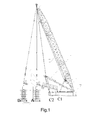
- a stepless luffing mechanism for a superlift counterweight of a crawler crane including a main luffing mast 0, a lift cylinder 2, a variable amplitude construction 3 for the superlift counterweight, a pulling plate 4 for the superlift counterweight, a superlift mast 5 and a measuring transducer installed under the variable amplitude construction 3 for the superlift counterweight.
- the lower end of the lift cylinder 2 connects to a superlift counterweight 1, the upper end of the lift cylinder 2 connects to the lower end of the front part of the variable amplitude construction 3 for the superlift counterweight; the upper end of the front part of the variable amplitude construction 3 for superlift counterweight connects to the lower end of the superlift counterweight pulling plate 4; the upper end of the superlift counterweight pulling plate 4 connects to the superlift mast 5 by a lifting rope, and the other end of the superlift mast 5 connects to one end of the platform 7.
- variable amplitude construction 3 for the superlift counterweight connects to a pin of the platform 7; the lift cylinder 2 drives the superlift counterweight 1 to move in a vertical direction to adjust its position along the vertical direction to ensure the superlift counterweight 1 is at an appropriate height.
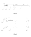
- FIG. 2 and Fig. 3 show a hydro-cylinder support 31, a translating hydro-cylinder 32 that is set in the front end of the hydro-cylinder support 31, hydro-cylinder piston rod support(s) 33 that is/are set in the front end of the translating hydro-cylinder 32, a connecting support 34 that is set in the front end of the hydro-cylinder piston rod support(s) 33 and pulling plates 35 that are set in the front end of the connecting support 34.
- the pulling plates 35 includes a first pulling plate 351 and a second pulling plate 352, the upper ends of the first pulling plate 351 and the second pulling plate 352 connect to the upper end of the lift cylinder 2, the lower ends of the first pulling plate 351 and the second pulling plate 352 connect to the lower end of the superlift counterweight pulling plate 4.
- the translating hydro-cylinder 32 drives a hydro-cylinder piston rod to move in a horizontal direction.
- the measuring transducer includes a length sensor 61 and an angle sensor 62; the length sensor 61 is installed at the lower part of the hydro-cylinder support 31 to measure the projecting length of the translating hydro-cylinder 32; the angle sensor 62 is installed at the lower part of the hydro-cylinder piston rod support(s) to measure the included angle between the variable amplitude construction 3 for superlift counterweight and the platform 7.
- the level position of the superlift counterweight is adjusted through controlling the telescopic movement of two superlift counterweight translating hydro-cylinders 32 of the variable amplitude construction 3 for the superlift counterweight to make it move away from the center of gravity of the vehicle or approach the center in a horizontal direction. It is pushed from point A to point B, or retracted from point B to point A.
- the superlift counterweight translating hydro-cylinder 32 may retract stroke.
- the superlift counterweight translating hydro-cylinder 32 is at a lock position with no movement.
- the superlift counterweight translating hydro-cylinder 32 may be pushed forward and the stroke is increased.
- a pressure sensor 8 and a proportional electromagnetic valve set in the translating hydro-cylinder 32 there is a set of pressure sensors 8 in the translating hydro-cylinders 32 which adopts synchronization control logic.
- the pressure of the two hydro-cylinders 32 monitored by the pressure sensors 8 will be equal. Otherwise, they will be unequal. If the pressure of the first translating hydro-cylinder 321 is not equal to the pressure of the second translating hydro-cylinder 322, the pressure value difference between the two translating hydro-cylinders has to be dealt with. Dealing with the value difference is mainly achieved by an electromagnetic valve.
- a first proportional electromagnetic valve 91 and second proportional electromagnetic valve 92 are separately configured in the first translating hydro-cylinder 321 and second translating hydro-cylinder 322.
- the speed of the hydro-cylinder action is determined by a given electric current.
- the opening of the electromagnetic valve will be bigger when the electric current is higher, thus the speed of the hydro-cylinder action will also be higher; the opening of the electromagnetic valve will be smaller when the electric current is lower, thus the speed of the hydro-cylinder action will also be lower. Therefore, the speed of the hydro-cylinder action is changed by adjusting and controlling the electric current of the first proportional electromagnetic valve 91 and the second proportional electromagnetic valve 92 set in the first translation hydro-cylinder 321 and second translation hydro-cylinder 322 in order to achieve the synchronization.
- the length sensor 61 and the angle sensor 62 separately monitor the length value of the variable amplitude construction 3 for the superlift counterweight and the value of the included angle ⁇ between the variable amplitude construction 3 for superlift counterweight and the platform 7 in real time. And the value of superlift radius, i.e. the position value of the superlift counterweight, can be calculated.
- the calculating method for the superlift counterweight working radius is as follows:
- a method for operating the stepless luffing mechanism including following steps:
- the present invention may realize the stepless variable amplitude of the superlift counterweight radius. And the variable amplitude range is larger and more convenient so that it could achieve the object of making hoisting operation range of the complete machine larger and the machine more stable, safer and more reliable in the hoisting operation. It further makes use of the operation space of the superlift mast, especially under conditions where the working space is limited, the center of gravity of the superlift counterweight may be changed through changing the stroke of the translating hydro-cylinder without changing the angle position of the superlift mast. Thereby space for variable amplitude of the superlift mast can be saved. And it is also easy to operate and convenient to use.
Applications Claiming Priority (2)
| Application Number | Priority Date | Filing Date | Title |
|---|---|---|---|
| CN2010101012614A CN101774514B (zh) | 2010-01-26 | 2010-01-26 | 履带起重机超起配重无级变幅机构及其操作方法 |
| PCT/CN2010/000847 WO2011091559A1 (zh) | 2010-01-26 | 2010-06-12 | 履带起重机超起配重无级变幅机构及其操作方法 |
Publications (3)
| Publication Number | Publication Date |
|---|---|
| EP2530046A1 EP2530046A1 (en) | 2012-12-05 |
| EP2530046A4 EP2530046A4 (en) | 2013-06-12 |
| EP2530046B1 true EP2530046B1 (en) | 2015-01-07 |
Family
ID=42511140
Family Applications (1)
| Application Number | Title | Priority Date | Filing Date |
|---|---|---|---|
| EP10844337.5A Not-in-force EP2530046B1 (en) | 2010-01-26 | 2010-06-12 | Stepless luffing mechanism for super-lifting counterweight of crawler crane and operating method thereof |
Country Status (6)
| Country | Link |
|---|---|
| US (1) | US20130020273A1 (zh) |
| EP (1) | EP2530046B1 (zh) |
| CN (1) | CN101774514B (zh) |
| BR (1) | BR112012018615A2 (zh) |
| SG (1) | SG182411A1 (zh) |
| WO (1) | WO2011091559A1 (zh) |
Families Citing this family (20)
| Publication number | Priority date | Publication date | Assignee | Title |
|---|---|---|---|---|
| US7967158B2 (en) | 2006-10-27 | 2011-06-28 | Manitowoc Crane Companies, Llc | Mobile lift crane with variable position counterweight |
| US9278834B2 (en) | 2009-08-06 | 2016-03-08 | Manitowoc Crane Group, LLC | Lift crane with moveable counterweight |
| CN102464269B (zh) * | 2010-11-09 | 2013-10-23 | 徐州重型机械有限公司 | 伸缩臂式起重机及其超起角度自动变换装置 |
| CN102718160B (zh) * | 2012-07-03 | 2014-07-23 | 徐工集团工程机械股份有限公司 | 起重机 |
| CN103708365B (zh) * | 2013-12-27 | 2015-12-02 | 浙江三一装备有限公司 | 一种履带起重机移动式后配重控制方法 |
| WO2015113048A1 (en) | 2014-01-27 | 2015-07-30 | Manitowoc Crane Companies, Llc | Lift crane with improved movable counterweight |
| EP3099620A4 (en) * | 2014-01-27 | 2017-10-11 | Manitowoc Crane Companies, Inc. | Height adjustment mechanism for an auxiliary member on a crane |
| CN105439017A (zh) * | 2016-01-11 | 2016-03-30 | 徐工集团工程机械股份有限公司 | 起重机 |
| CN105584941B (zh) * | 2016-02-29 | 2017-06-30 | 浙江三一装备有限公司 | 一种桁架臂变径器和履带起重机 |
| US11097927B1 (en) * | 2016-04-20 | 2021-08-24 | Link-Belt Cranes, L.P., Lllp | Lifting machine with counterweight sensing system and related methods |
| CN106042402A (zh) * | 2016-08-11 | 2016-10-26 | 成都为帆斯通科技有限公司 | 一种3d打印机的平衡调节装置 |
| CN106542445B (zh) * | 2016-12-24 | 2018-10-23 | 中国一冶集团有限公司 | 履带起重机可控式配重系统 |
| CA3061001A1 (en) * | 2017-04-26 | 2018-11-01 | Sucof B.V. | Crane, method for assembling a crane and method for disassembling a crane |
| CN112533859B (zh) * | 2018-07-24 | 2023-10-10 | 玛姆特控股公司 | 起重机、用于组装起重机的方法和用于拆卸起重机的方法 |
| CN109594966B (zh) * | 2018-11-23 | 2022-05-06 | 上海中联重科桩工机械有限公司 | 旋挖钻机倒桅控制系统和控制方法 |
| CN110046429B (zh) * | 2019-04-16 | 2024-03-19 | 西安长庆科技工程有限责任公司 | 一种用于一体化装置的吊架及其设计方法 |
| US11511976B2 (en) | 2019-10-07 | 2022-11-29 | Caterpillar Inc. | System and method for determining a lifting capacity of a machine |
| CN114132853B (zh) * | 2020-11-03 | 2022-08-30 | 中联重科股份有限公司 | 起重设备的安全控制方法及系统 |
| CN113148864A (zh) * | 2021-04-28 | 2021-07-23 | 徐工集团工程机械股份有限公司建设机械分公司 | 起重机及其控制方法 |
| CN113742869A (zh) * | 2021-09-28 | 2021-12-03 | 徐工集团工程机械股份有限公司建设机械分公司 | 一种起重机性能提升方法 |
Family Cites Families (16)
| Publication number | Priority date | Publication date | Assignee | Title |
|---|---|---|---|---|
| US4589076A (en) * | 1983-10-17 | 1986-05-13 | Kabushiki Kaisha Kobe Seiko Sho | Method for controlling stretching and contracting operations of telescopic multistage boom |
| JPS61203095A (ja) * | 1985-03-04 | 1986-09-08 | 株式会社神戸製鋼所 | カウンタバランス型クレ−ン |
| US5941401A (en) * | 1997-01-29 | 1999-08-24 | Manitowoc Crane Group, Inc. | Counterweight handling system for ring supported cranes |
| DE19734789A1 (de) * | 1997-08-07 | 1999-03-04 | Mannesmann Ag | Gegenmassewagen eines Kranes |
| DE29816385U1 (de) * | 1998-09-11 | 1999-04-08 | Liebherr Werk Ehingen | Kran, vorzugsweise Derrickkran |
| DE19857779A1 (de) * | 1998-12-04 | 2000-06-15 | Mannesmann Ag | Kran, insbesondere Fahrzeugkran |
| DE10155006B4 (de) * | 2001-11-06 | 2004-12-16 | Terex-Demag Gmbh & Co. Kg | Fahrzeugkran mit Superlifteinrichtung |
| CN100465846C (zh) * | 2006-09-15 | 2009-03-04 | 上海三一科技有限公司 | 履带起重机超起工况下力矩控制的方法与装置 |
| US7967158B2 (en) * | 2006-10-27 | 2011-06-28 | Manitowoc Crane Companies, Llc | Mobile lift crane with variable position counterweight |
| US7546928B2 (en) * | 2006-10-27 | 2009-06-16 | Manitowoc Crane Companies, Inc. | Mobile lift crane with variable position counterweight |
| JP5276867B2 (ja) * | 2007-04-09 | 2013-08-28 | マニタウォック クレイン カンパニーズ インコーポレイテッド | 可変位置カウンタウエイトユニットを装備している自走式リフトクレーン及びその操作方法 |
| US8622228B2 (en) * | 2008-09-19 | 2014-01-07 | Manitowoc Crane Companies, Llc | Boom hoist transportation system and crane using same |
| CN201292224Y (zh) * | 2008-11-25 | 2009-08-19 | 上海三一科技有限公司 | 履带起重机移动配重装置 |
| US8960460B2 (en) * | 2009-03-09 | 2015-02-24 | Manitowoc Crane Companies, Llc | Counterweight block and assemblies for cranes |
| US9278834B2 (en) * | 2009-08-06 | 2016-03-08 | Manitowoc Crane Group, LLC | Lift crane with moveable counterweight |
| JP5625377B2 (ja) * | 2010-02-09 | 2014-11-19 | コベルコクレーン株式会社 | 移動式クレーン |
-
2010
- 2010-01-26 CN CN2010101012614A patent/CN101774514B/zh active Active
- 2010-06-12 US US13/515,810 patent/US20130020273A1/en not_active Abandoned
- 2010-06-12 WO PCT/CN2010/000847 patent/WO2011091559A1/zh active Application Filing
- 2010-06-12 SG SG2012050183A patent/SG182411A1/en unknown
- 2010-06-12 BR BR112012018615A patent/BR112012018615A2/pt not_active IP Right Cessation
- 2010-06-12 EP EP10844337.5A patent/EP2530046B1/en not_active Not-in-force
Also Published As
| Publication number | Publication date |
|---|---|
| WO2011091559A1 (zh) | 2011-08-04 |
| CN101774514B (zh) | 2012-02-22 |
| EP2530046A1 (en) | 2012-12-05 |
| SG182411A1 (en) | 2012-08-30 |
| CN101774514A (zh) | 2010-07-14 |
| BR112012018615A2 (pt) | 2016-05-03 |
| EP2530046A4 (en) | 2013-06-12 |
| US20130020273A1 (en) | 2013-01-24 |
Similar Documents
| Publication | Publication Date | Title |
|---|---|---|
| EP2530046B1 (en) | Stepless luffing mechanism for super-lifting counterweight of crawler crane and operating method thereof | |
| US11208303B2 (en) | Lift crane with improved movable counterweight | |
| CN201901539U (zh) | 内爬式和外爬式的动臂式塔机 | |
| US4752012A (en) | Crane control means employing load sensing devices | |
| EP2246289B1 (en) | Crane with boom raising assist structure | |
| EP2281771A1 (en) | Lift crane with movable counterweight | |
| CN101357739B (zh) | 动臂式组塔专用塔式起重机 | |
| CN206767514U (zh) | 一种移动专用吊车 | |
| CN105253786A (zh) | 折叠臂式随车起重机 | |
| CN201485194U (zh) | 60t步履式全回转架梁起重机 | |
| CN102774757A (zh) | 工程机械 | |
| CN201214598Y (zh) | 动臂式组塔专用塔式起重机 | |
| CN102303821A (zh) | 基于钢绳牵引变幅的吊臂平衡式动臂塔机 | |
| CN202296907U (zh) | 基于钢绳牵引变幅的吊臂平衡式动臂塔机 | |
| CN208949739U (zh) | 用于牵索挂篮的升降工作平台 | |
| CN205892576U (zh) | 快速架设塔式起重机的起重臂翻折装置 | |
| CN103253602B (zh) | 可提升式自行履带车超起装置及起重机 | |
| CN202322242U (zh) | 旋转式井架作业车 | |
| CN108167272A (zh) | 一种拖拉机液压提升系统终检试验装置 | |
| CN207961154U (zh) | 一种拖拉机液压提升系统终检试验装置 | |
| CN203474321U (zh) | 一种用于组立输电线路铁塔的塔式起重机 | |
| CN206359148U (zh) | 一种车载钻机用吊车 | |
| CN106044587B (zh) | 一种固定式起重机 | |
| CN217600239U (zh) | 一种用于起重机的监视装置 | |
| CN212953908U (zh) | 一种建筑工程用可升降的无轨门式起重机 |
Legal Events
| Date | Code | Title | Description |
|---|---|---|---|
| PUAI | Public reference made under article 153(3) epc to a published international application that has entered the european phase |
Free format text: ORIGINAL CODE: 0009012 |
|
| 17P | Request for examination filed |
Effective date: 20120618 |
|
| AK | Designated contracting states |
Kind code of ref document: A1 Designated state(s): AL AT BE BG CH CY CZ DE DK EE ES FI FR GB GR HR HU IE IS IT LI LT LU LV MC MK MT NL NO PL PT RO SE SI SK SM TR |
|
| DAX | Request for extension of the european patent (deleted) | ||
| A4 | Supplementary search report drawn up and despatched |
Effective date: 20130513 |
|
| RIC1 | Information provided on ipc code assigned before grant |
Ipc: B66C 23/76 20060101AFI20130506BHEP |
|
| 17Q | First examination report despatched |
Effective date: 20140106 |
|
| GRAP | Despatch of communication of intention to grant a patent |
Free format text: ORIGINAL CODE: EPIDOSNIGR1 |
|
| INTG | Intention to grant announced |
Effective date: 20140729 |
|
| GRAS | Grant fee paid |
Free format text: ORIGINAL CODE: EPIDOSNIGR3 |
|
| GRAA | (expected) grant |
Free format text: ORIGINAL CODE: 0009210 |
|
| AK | Designated contracting states |
Kind code of ref document: B1 Designated state(s): AL AT BE BG CH CY CZ DE DK EE ES FI FR GB GR HR HU IE IS IT LI LT LU LV MC MK MT NL NO PL PT RO SE SI SK SM TR |
|
| REG | Reference to a national code |
Ref country code: GB Ref legal event code: FG4D |
|
| REG | Reference to a national code |
Ref country code: CH Ref legal event code: EP |
|
| REG | Reference to a national code |
Ref country code: IE Ref legal event code: FG4D |
|
| REG | Reference to a national code |
Ref country code: AT Ref legal event code: REF Ref document number: 705548 Country of ref document: AT Kind code of ref document: T Effective date: 20150215 |
|
| REG | Reference to a national code |
Ref country code: DE Ref legal event code: R096 Ref document number: 602010021738 Country of ref document: DE Effective date: 20150226 |
|
| REG | Reference to a national code |
Ref country code: NL Ref legal event code: VDEP Effective date: 20150107 |
|
| REG | Reference to a national code |
Ref country code: AT Ref legal event code: MK05 Ref document number: 705548 Country of ref document: AT Kind code of ref document: T Effective date: 20150107 |
|
| REG | Reference to a national code |
Ref country code: LT Ref legal event code: MG4D |
|
| PG25 | Lapsed in a contracting state [announced via postgrant information from national office to epo] |
Ref country code: LT Free format text: LAPSE BECAUSE OF FAILURE TO SUBMIT A TRANSLATION OF THE DESCRIPTION OR TO PAY THE FEE WITHIN THE PRESCRIBED TIME-LIMIT Effective date: 20150107 Ref country code: ES Free format text: LAPSE BECAUSE OF FAILURE TO SUBMIT A TRANSLATION OF THE DESCRIPTION OR TO PAY THE FEE WITHIN THE PRESCRIBED TIME-LIMIT Effective date: 20150107 Ref country code: SE Free format text: LAPSE BECAUSE OF FAILURE TO SUBMIT A TRANSLATION OF THE DESCRIPTION OR TO PAY THE FEE WITHIN THE PRESCRIBED TIME-LIMIT Effective date: 20150107 Ref country code: NO Free format text: LAPSE BECAUSE OF FAILURE TO SUBMIT A TRANSLATION OF THE DESCRIPTION OR TO PAY THE FEE WITHIN THE PRESCRIBED TIME-LIMIT Effective date: 20150407 Ref country code: FI Free format text: LAPSE BECAUSE OF FAILURE TO SUBMIT A TRANSLATION OF THE DESCRIPTION OR TO PAY THE FEE WITHIN THE PRESCRIBED TIME-LIMIT Effective date: 20150107 Ref country code: BG Free format text: LAPSE BECAUSE OF FAILURE TO SUBMIT A TRANSLATION OF THE DESCRIPTION OR TO PAY THE FEE WITHIN THE PRESCRIBED TIME-LIMIT Effective date: 20150407 Ref country code: HR Free format text: LAPSE BECAUSE OF FAILURE TO SUBMIT A TRANSLATION OF THE DESCRIPTION OR TO PAY THE FEE WITHIN THE PRESCRIBED TIME-LIMIT Effective date: 20150107 |
|
| PG25 | Lapsed in a contracting state [announced via postgrant information from national office to epo] |
Ref country code: GR Free format text: LAPSE BECAUSE OF FAILURE TO SUBMIT A TRANSLATION OF THE DESCRIPTION OR TO PAY THE FEE WITHIN THE PRESCRIBED TIME-LIMIT Effective date: 20150408 Ref country code: IS Free format text: LAPSE BECAUSE OF FAILURE TO SUBMIT A TRANSLATION OF THE DESCRIPTION OR TO PAY THE FEE WITHIN THE PRESCRIBED TIME-LIMIT Effective date: 20150507 Ref country code: AT Free format text: LAPSE BECAUSE OF FAILURE TO SUBMIT A TRANSLATION OF THE DESCRIPTION OR TO PAY THE FEE WITHIN THE PRESCRIBED TIME-LIMIT Effective date: 20150107 Ref country code: PL Free format text: LAPSE BECAUSE OF FAILURE TO SUBMIT A TRANSLATION OF THE DESCRIPTION OR TO PAY THE FEE WITHIN THE PRESCRIBED TIME-LIMIT Effective date: 20150107 Ref country code: LV Free format text: LAPSE BECAUSE OF FAILURE TO SUBMIT A TRANSLATION OF THE DESCRIPTION OR TO PAY THE FEE WITHIN THE PRESCRIBED TIME-LIMIT Effective date: 20150107 Ref country code: NL Free format text: LAPSE BECAUSE OF FAILURE TO SUBMIT A TRANSLATION OF THE DESCRIPTION OR TO PAY THE FEE WITHIN THE PRESCRIBED TIME-LIMIT Effective date: 20150107 |
|
| REG | Reference to a national code |
Ref country code: DE Ref legal event code: R097 Ref document number: 602010021738 Country of ref document: DE |
|
| PG25 | Lapsed in a contracting state [announced via postgrant information from national office to epo] |
Ref country code: DK Free format text: LAPSE BECAUSE OF FAILURE TO SUBMIT A TRANSLATION OF THE DESCRIPTION OR TO PAY THE FEE WITHIN THE PRESCRIBED TIME-LIMIT Effective date: 20150107 Ref country code: SK Free format text: LAPSE BECAUSE OF FAILURE TO SUBMIT A TRANSLATION OF THE DESCRIPTION OR TO PAY THE FEE WITHIN THE PRESCRIBED TIME-LIMIT Effective date: 20150107 Ref country code: RO Free format text: LAPSE BECAUSE OF FAILURE TO SUBMIT A TRANSLATION OF THE DESCRIPTION OR TO PAY THE FEE WITHIN THE PRESCRIBED TIME-LIMIT Effective date: 20150107 Ref country code: EE Free format text: LAPSE BECAUSE OF FAILURE TO SUBMIT A TRANSLATION OF THE DESCRIPTION OR TO PAY THE FEE WITHIN THE PRESCRIBED TIME-LIMIT Effective date: 20150107 Ref country code: CZ Free format text: LAPSE BECAUSE OF FAILURE TO SUBMIT A TRANSLATION OF THE DESCRIPTION OR TO PAY THE FEE WITHIN THE PRESCRIBED TIME-LIMIT Effective date: 20150107 |
|
| PLBE | No opposition filed within time limit |
Free format text: ORIGINAL CODE: 0009261 |
|
| STAA | Information on the status of an ep patent application or granted ep patent |
Free format text: STATUS: NO OPPOSITION FILED WITHIN TIME LIMIT |
|
| 26N | No opposition filed |
Effective date: 20151008 |
|
| PG25 | Lapsed in a contracting state [announced via postgrant information from national office to epo] |
Ref country code: IT Free format text: LAPSE BECAUSE OF FAILURE TO SUBMIT A TRANSLATION OF THE DESCRIPTION OR TO PAY THE FEE WITHIN THE PRESCRIBED TIME-LIMIT Effective date: 20150107 |
|
| REG | Reference to a national code |
Ref country code: DE Ref legal event code: R119 Ref document number: 602010021738 Country of ref document: DE |
|
| PG25 | Lapsed in a contracting state [announced via postgrant information from national office to epo] |
Ref country code: MC Free format text: LAPSE BECAUSE OF FAILURE TO SUBMIT A TRANSLATION OF THE DESCRIPTION OR TO PAY THE FEE WITHIN THE PRESCRIBED TIME-LIMIT Effective date: 20150107 |
|
| REG | Reference to a national code |
Ref country code: CH Ref legal event code: PL |
|
| GBPC | Gb: european patent ceased through non-payment of renewal fee |
Effective date: 20150612 |
|
| PG25 | Lapsed in a contracting state [announced via postgrant information from national office to epo] |
Ref country code: SI Free format text: LAPSE BECAUSE OF FAILURE TO SUBMIT A TRANSLATION OF THE DESCRIPTION OR TO PAY THE FEE WITHIN THE PRESCRIBED TIME-LIMIT Effective date: 20150107 Ref country code: LU Free format text: LAPSE BECAUSE OF FAILURE TO SUBMIT A TRANSLATION OF THE DESCRIPTION OR TO PAY THE FEE WITHIN THE PRESCRIBED TIME-LIMIT Effective date: 20150612 |
|
| REG | Reference to a national code |
Ref country code: IE Ref legal event code: MM4A |
|
| REG | Reference to a national code |
Ref country code: FR Ref legal event code: ST Effective date: 20160229 |
|
| PG25 | Lapsed in a contracting state [announced via postgrant information from national office to epo] |
Ref country code: DE Free format text: LAPSE BECAUSE OF NON-PAYMENT OF DUE FEES Effective date: 20160101 Ref country code: GB Free format text: LAPSE BECAUSE OF NON-PAYMENT OF DUE FEES Effective date: 20150612 Ref country code: CH Free format text: LAPSE BECAUSE OF NON-PAYMENT OF DUE FEES Effective date: 20150630 Ref country code: IE Free format text: LAPSE BECAUSE OF NON-PAYMENT OF DUE FEES Effective date: 20150612 Ref country code: LI Free format text: LAPSE BECAUSE OF NON-PAYMENT OF DUE FEES Effective date: 20150630 |
|
| PG25 | Lapsed in a contracting state [announced via postgrant information from national office to epo] |
Ref country code: FR Free format text: LAPSE BECAUSE OF NON-PAYMENT OF DUE FEES Effective date: 20150630 Ref country code: BE Free format text: LAPSE BECAUSE OF FAILURE TO SUBMIT A TRANSLATION OF THE DESCRIPTION OR TO PAY THE FEE WITHIN THE PRESCRIBED TIME-LIMIT Effective date: 20150107 |
|
| PG25 | Lapsed in a contracting state [announced via postgrant information from national office to epo] |
Ref country code: MT Free format text: LAPSE BECAUSE OF FAILURE TO SUBMIT A TRANSLATION OF THE DESCRIPTION OR TO PAY THE FEE WITHIN THE PRESCRIBED TIME-LIMIT Effective date: 20150107 |
|
| PG25 | Lapsed in a contracting state [announced via postgrant information from national office to epo] |
Ref country code: HU Free format text: LAPSE BECAUSE OF FAILURE TO SUBMIT A TRANSLATION OF THE DESCRIPTION OR TO PAY THE FEE WITHIN THE PRESCRIBED TIME-LIMIT; INVALID AB INITIO Effective date: 20100612 Ref country code: SM Free format text: LAPSE BECAUSE OF FAILURE TO SUBMIT A TRANSLATION OF THE DESCRIPTION OR TO PAY THE FEE WITHIN THE PRESCRIBED TIME-LIMIT Effective date: 20150107 |
|
| PG25 | Lapsed in a contracting state [announced via postgrant information from national office to epo] |
Ref country code: CY Free format text: LAPSE BECAUSE OF FAILURE TO SUBMIT A TRANSLATION OF THE DESCRIPTION OR TO PAY THE FEE WITHIN THE PRESCRIBED TIME-LIMIT Effective date: 20150107 |
|
| PG25 | Lapsed in a contracting state [announced via postgrant information from national office to epo] |
Ref country code: TR Free format text: LAPSE BECAUSE OF FAILURE TO SUBMIT A TRANSLATION OF THE DESCRIPTION OR TO PAY THE FEE WITHIN THE PRESCRIBED TIME-LIMIT Effective date: 20150107 |
|
| PG25 | Lapsed in a contracting state [announced via postgrant information from national office to epo] |
Ref country code: MK Free format text: LAPSE BECAUSE OF FAILURE TO SUBMIT A TRANSLATION OF THE DESCRIPTION OR TO PAY THE FEE WITHIN THE PRESCRIBED TIME-LIMIT Effective date: 20150107 Ref country code: PT Free format text: LAPSE BECAUSE OF FAILURE TO SUBMIT A TRANSLATION OF THE DESCRIPTION OR TO PAY THE FEE WITHIN THE PRESCRIBED TIME-LIMIT Effective date: 20150107 |
|
| PG25 | Lapsed in a contracting state [announced via postgrant information from national office to epo] |
Ref country code: AL Free format text: LAPSE BECAUSE OF FAILURE TO SUBMIT A TRANSLATION OF THE DESCRIPTION OR TO PAY THE FEE WITHIN THE PRESCRIBED TIME-LIMIT Effective date: 20150107 |