EP2529679B1 - Schalldämpfungshülse zum Aufsetzen auf ein Druckwellengerät - Google Patents
Schalldämpfungshülse zum Aufsetzen auf ein Druckwellengerät Download PDFInfo
- Publication number
- EP2529679B1 EP2529679B1 EP20120170016 EP12170016A EP2529679B1 EP 2529679 B1 EP2529679 B1 EP 2529679B1 EP 20120170016 EP20120170016 EP 20120170016 EP 12170016 A EP12170016 A EP 12170016A EP 2529679 B1 EP2529679 B1 EP 2529679B1
- Authority
- EP
- European Patent Office
- Prior art keywords
- sound absorbing
- absorbing sleeve
- housing
- sound
- sleeve
- Prior art date
- Legal status (The legal status is an assumption and is not a legal conclusion. Google has not performed a legal analysis and makes no representation as to the accuracy of the status listed.)
- Active
Links
Images


Classifications
-
- A—HUMAN NECESSITIES
- A61—MEDICAL OR VETERINARY SCIENCE; HYGIENE
- A61B—DIAGNOSIS; SURGERY; IDENTIFICATION
- A61B17/00—Surgical instruments, devices or methods
- A61B17/22—Implements for squeezing-off ulcers or the like on inner organs of the body; Implements for scraping-out cavities of body organs, e.g. bones; for invasive removal or destruction of calculus using mechanical vibrations; for removing obstructions in blood vessels, not otherwise provided for
- A61B17/22004—Implements for squeezing-off ulcers or the like on inner organs of the body; Implements for scraping-out cavities of body organs, e.g. bones; for invasive removal or destruction of calculus using mechanical vibrations; for removing obstructions in blood vessels, not otherwise provided for using mechanical vibrations, e.g. ultrasonic shock waves
-
- A—HUMAN NECESSITIES
- A61—MEDICAL OR VETERINARY SCIENCE; HYGIENE
- A61H—PHYSICAL THERAPY APPARATUS, e.g. DEVICES FOR LOCATING OR STIMULATING REFLEX POINTS IN THE BODY; ARTIFICIAL RESPIRATION; MASSAGE; BATHING DEVICES FOR SPECIAL THERAPEUTIC OR HYGIENIC PURPOSES OR SPECIFIC PARTS OF THE BODY
- A61H23/00—Percussion or vibration massage, e.g. using supersonic vibration; Suction-vibration massage; Massage with moving diaphragms
- A61H23/008—Percussion or vibration massage, e.g. using supersonic vibration; Suction-vibration massage; Massage with moving diaphragms using shock waves
-
- A—HUMAN NECESSITIES
- A61—MEDICAL OR VETERINARY SCIENCE; HYGIENE
- A61H—PHYSICAL THERAPY APPARATUS, e.g. DEVICES FOR LOCATING OR STIMULATING REFLEX POINTS IN THE BODY; ARTIFICIAL RESPIRATION; MASSAGE; BATHING DEVICES FOR SPECIAL THERAPEUTIC OR HYGIENIC PURPOSES OR SPECIFIC PARTS OF THE BODY
- A61H23/00—Percussion or vibration massage, e.g. using supersonic vibration; Suction-vibration massage; Massage with moving diaphragms
- A61H23/02—Percussion or vibration massage, e.g. using supersonic vibration; Suction-vibration massage; Massage with moving diaphragms with electric or magnetic drive
-
- A—HUMAN NECESSITIES
- A61—MEDICAL OR VETERINARY SCIENCE; HYGIENE
- A61H—PHYSICAL THERAPY APPARATUS, e.g. DEVICES FOR LOCATING OR STIMULATING REFLEX POINTS IN THE BODY; ARTIFICIAL RESPIRATION; MASSAGE; BATHING DEVICES FOR SPECIAL THERAPEUTIC OR HYGIENIC PURPOSES OR SPECIFIC PARTS OF THE BODY
- A61H23/00—Percussion or vibration massage, e.g. using supersonic vibration; Suction-vibration massage; Massage with moving diaphragms
- A61H23/04—Percussion or vibration massage, e.g. using supersonic vibration; Suction-vibration massage; Massage with moving diaphragms with hydraulic or pneumatic drive
-
- A—HUMAN NECESSITIES
- A61—MEDICAL OR VETERINARY SCIENCE; HYGIENE
- A61B—DIAGNOSIS; SURGERY; IDENTIFICATION
- A61B17/00—Surgical instruments, devices or methods
- A61B2017/00535—Surgical instruments, devices or methods pneumatically or hydraulically operated
- A61B2017/00544—Surgical instruments, devices or methods pneumatically or hydraulically operated pneumatically
-
- A—HUMAN NECESSITIES
- A61—MEDICAL OR VETERINARY SCIENCE; HYGIENE
- A61B—DIAGNOSIS; SURGERY; IDENTIFICATION
- A61B17/00—Surgical instruments, devices or methods
- A61B17/22—Implements for squeezing-off ulcers or the like on inner organs of the body; Implements for scraping-out cavities of body organs, e.g. bones; for invasive removal or destruction of calculus using mechanical vibrations; for removing obstructions in blood vessels, not otherwise provided for
- A61B17/225—Implements for squeezing-off ulcers or the like on inner organs of the body; Implements for scraping-out cavities of body organs, e.g. bones; for invasive removal or destruction of calculus using mechanical vibrations; for removing obstructions in blood vessels, not otherwise provided for for extracorporeal shock wave lithotripsy [ESWL], e.g. by using ultrasonic waves
- A61B17/2251—Implements for squeezing-off ulcers or the like on inner organs of the body; Implements for scraping-out cavities of body organs, e.g. bones; for invasive removal or destruction of calculus using mechanical vibrations; for removing obstructions in blood vessels, not otherwise provided for for extracorporeal shock wave lithotripsy [ESWL], e.g. by using ultrasonic waves characterised by coupling elements between the apparatus, e.g. shock wave apparatus or locating means, and the patient, e.g. details of bags, pressure control of bag on patient
- A61B2017/2253—Implements for squeezing-off ulcers or the like on inner organs of the body; Implements for scraping-out cavities of body organs, e.g. bones; for invasive removal or destruction of calculus using mechanical vibrations; for removing obstructions in blood vessels, not otherwise provided for for extracorporeal shock wave lithotripsy [ESWL], e.g. by using ultrasonic waves characterised by coupling elements between the apparatus, e.g. shock wave apparatus or locating means, and the patient, e.g. details of bags, pressure control of bag on patient using a coupling gel or liquid
-
- A—HUMAN NECESSITIES
- A61—MEDICAL OR VETERINARY SCIENCE; HYGIENE
- A61H—PHYSICAL THERAPY APPARATUS, e.g. DEVICES FOR LOCATING OR STIMULATING REFLEX POINTS IN THE BODY; ARTIFICIAL RESPIRATION; MASSAGE; BATHING DEVICES FOR SPECIAL THERAPEUTIC OR HYGIENIC PURPOSES OR SPECIFIC PARTS OF THE BODY
- A61H1/00—Apparatus for passive exercising; Vibrating apparatus; Chiropractic devices, e.g. body impacting devices, external devices for briefly extending or aligning unbroken bones
- A61H1/008—Apparatus for applying pressure or blows almost perpendicular to the body or limb axis, e.g. chiropractic devices for repositioning vertebrae, correcting deformation
-
- A—HUMAN NECESSITIES
- A61—MEDICAL OR VETERINARY SCIENCE; HYGIENE
- A61H—PHYSICAL THERAPY APPARATUS, e.g. DEVICES FOR LOCATING OR STIMULATING REFLEX POINTS IN THE BODY; ARTIFICIAL RESPIRATION; MASSAGE; BATHING DEVICES FOR SPECIAL THERAPEUTIC OR HYGIENIC PURPOSES OR SPECIFIC PARTS OF THE BODY
- A61H23/00—Percussion or vibration massage, e.g. using supersonic vibration; Suction-vibration massage; Massage with moving diaphragms
- A61H2023/002—Percussion or vibration massage, e.g. using supersonic vibration; Suction-vibration massage; Massage with moving diaphragms having a percussion element combined with a passive spacer element for bearing against the skin
-
- A—HUMAN NECESSITIES
- A61—MEDICAL OR VETERINARY SCIENCE; HYGIENE
- A61H—PHYSICAL THERAPY APPARATUS, e.g. DEVICES FOR LOCATING OR STIMULATING REFLEX POINTS IN THE BODY; ARTIFICIAL RESPIRATION; MASSAGE; BATHING DEVICES FOR SPECIAL THERAPEUTIC OR HYGIENIC PURPOSES OR SPECIFIC PARTS OF THE BODY
- A61H2201/00—Characteristics of apparatus not provided for in the preceding codes
- A61H2201/16—Physical interface with patient
- A61H2201/1683—Surface of interface
- A61H2201/1688—Surface of interface disposable
Definitions
- the present invention relates to a sound attenuation sleeve for placement on a pressure wave device for the treatment of the human or animal body by mechanical pressure waves.
- Devices for the treatment with mechanical pressure waves are known per se, in particular in the field of lithotripsy. There, with focused mechanical pressure waves body concrements, such as stones in the body tissue, smashed. In addition to the generation by electrical discharges in the water and devices have been developed that generate mechanical pressure waves by the collision of an accelerated impact part and an impact body. Such devices are used both in lithotripsy and in other treatments of biological body substances, in particular the treatment of muscle diseases and disorders in the transition region between muscles and bones and applications in the dermatological area are mentioned.
- the WO 99/08598 A1 describes an attachment for an ultrasonic probe, which is to prevent contamination of the probe and therefore covers the active probe head.
- the US 6,039,694 A shows a hygiene set for ultrasound devices, namely a foil covering the active probe head and a clip holding it on the device.
- a grip area is specially adapted to a partially closed to the hand of the hand.
- the present invention is based on the technical problem of improving the performance of pressure wave devices with impact part and impact body.
- the invention is equally directed to a pressure wave device with a movable impact part and impact body, which are mounted in a housing of the pressure wave device, wherein on the outside of the housing a sound-damping sleeve according to the invention is provided.
- the coupling-in direction mentioned at the outset in connection with the length determination corresponds to a main propagation direction of the pressure waves which, after averaging, can also result as a direction of gravity of a multiplicity of propagation directions, for example in the case of radially propagating pressure waves.
- a directional component typically a principal component
- the specified minimum length of the sound-absorbing sleeve is based on the baffle body, specifically the length taken in the coupling-in direction of its part arranged inside the housing. Parts of the impact body protruding from the housing thus remain out of consideration when viewing the length, and the part of the impact body taken into consideration is surrounded by the housing in sectional planes (not necessarily complete, but preferably) that are perpendicular to the coupling-in direction.
- the inventors have found that there is a generation of noise, even if a side of the impact body opposite a baffle surface for the impact part rests against the body part to be treated and the sound propagation should actually be damped thereby. This can lead to considerable noise nuisance, both for the treating person and for the patient.
- the lateral sound propagation can be advantageously reduced, which experience has shown that a certain minimum length of the sound-absorbing sleeve must be maintained.
- the length of the sound-absorbing sleeve in the coupling-in direction is greater than in this order increasingly preferably 25%, 50%, 75% or even 100% of the length taken in the same direction of the part of the impact body extending inside the housing, the length of the sound-deadening sleeve being particularly preferred in Einkoppelraum thus greater than the taken in the same direction length of extending within the housing part of the impact body.
- the length of the baffle body will be discussed, although the length of the part extending inside the housing is meant, except in the case of an expressly different indication.
- the impact body can then be completely surrounded by the sound-absorbing sleeve, for example with respect to directions perpendicular to the coupling-in direction, so that the sound propagating sideways from the impact body is damped over the entire length of the impact body.
- the sound-absorbing sleeve is designed for such a system on the housing, that it covers a provided for the impact of the impact part of the impact body perpendicular to the coupling direction to the outside.
- a plane perpendicular to the coupling direction, to which provided for the impact of the impact member baffle tangential "plane of the impact” thus cuts the sound attenuation sleeve.
- the plane of impact intersects the sound attenuation sleeve with respect to the coupling direction in a central region so that the plane of impact divides the sound attenuation sleeve into two parts and each of the halves measures at least 25%, more preferably at least 35% of the total sound attenuation sleeve length ,
- the sound-absorbing sleeve is designed as a tubular body, which may have an annular cross-sectional shape, for example, in the case of a cylindrically symmetrical housing.
- the ends of the tubular body are open.
- a sound-deadening sleeve which is open towards the body can also permit a direct contact of the impact body with the body and a correspondingly good coupling of the pressure waves.
- the sound attenuation sleeve is preferably arranged on the housing such that it also covers a part of the impact body protruding from the housing perpendicularly to the coupling-in direction, which helps to reduce the sound propagation emanating from the area not otherwise shielded from the housing.
- the coupling can also be improved by the application of a coupling gel, which is then present during the treatment as a thin film between the coupling surface of the impact body and the body.
- a further preferred embodiment can offer advantages, namely, if the sound-absorbing sleeve in the region of the body-facing open end is so spaced from the housing, that a Schalldämpfungshülseninnenwand Scheme together with the housing limits a volume.
- a coupling gel can be filled namely, preferably before a treatment. More preferred is that of Schalldämpfungshülseninnenwand Scheme and
- the filling with coupling gel can be done by the open towards the body end of the sound attenuation sleeve; Preferably, a separate opening is provided for this purpose, which, for example, allows access to the coupling gel reservoir oriented obliquely to the coupling-in direction from a sleeve outer wall area.
- oblique means an angle included with the main propagation direction (the smaller of two angles 180 ° together) of more preferably at least 30 °, 45 °, 60 °, 75 °, 85 ° in this order.
- a coupling gel reservoir open to the body and a body closed towards the body.
- the Koppelgelabgabe can be done in the latter, for example, by the therapist presses on a coupling gel opposite sleeve outer wall region and thus causes a temporary opening of the otherwise closed volume by the pressure of the coupling gel, such as the coupling gel between an otherwise applied to the housing collar of a sound absorbing sleeve made of elastomeric material and is pushed through the housing.
- an additional opening can offer the advantage that thereby escape air through the opening facing the body, so the reservoir can be filled substantially free of air bubbles.
- an additional opening could also serve the vent.
- the coupling gel is laterally displaced during a treatment and thus usually spread over the skin within a short time.
- a treating doctor or therapist has to push the gel over and over again or apply a new gel; In both cases the treatment is impaired or it must be interrupted.
- the inner wall area spaced from the housing can at least partially prevent the coupling gel from sliding sideways.
- the otherwise open volume is then limited by the skin of the patient, the coupling gel is thus held together during the treatment in a (within certain limits) closed volume.
- fewer coupling gel can be provided, which is advantageous in terms of cost, for example, or the attention of the treating person can remain focused on the actual treatment.
- Another embodiment relates to an inwardly directed circumferential collar through which the body facing opening of the sound attenuation sleeve is tapered.
- a collar for example, serve as a stop when placing the sound attenuation sleeve and so pretend a relative position of the sound attenuation sleeve and pressure wave device.
- the collar is particularly preferably provided in connection with the inner wall region spaced apart from the housing, ie the coupling gel reservoir, and can thus guide the coupling gel at the open end in the direction of the coupling surface of the impact body.
- the collar can also abut against the housing in the manner described above and thus close the coupling gel reservoir to the body (and open only under pressure and release coupling gel);
- the coupling gel reservoir is preferably open to the body even in the case of an intended collar, even if no coupling gel presses against the collar.
- the volume of the coupling-gel reservoir can be changed when the sound-deadening sleeve is pressed against the body to be treated, thus also forcing out the coupling gel.
- This can also take place, for example, by a relative displacement between the sound-damping sleeve (that is to say the region of the housing which is at a distance from the housing) and the housing perpendicular to the coupling-in direction.
- the diameter of the aperture tapered by the collar is preferably at least 10%, more preferably at least in this order 15%, 20%, 25%, 30%, smaller than the inside diameter of the area of the sound-deadening sleeve intended for installation on the housing (ie also smaller than the outside diameter of the housing).
- a cylindrical geometry is preferred for impact body, housing and sound-deadening sleeve, embodiments with other cross-sectional shapes should also be included and in such a case the diameter specification is based on the minimum diameter, ie, for example, in the case of a square cross-section on the edge length.
- a material with a modulus of elasticity of less than 10 GPa, in this order, more preferably of less than 5, 3, 2, 1 GPa, is preferred for the soundproofing sleeve.
- a sound-damping sleeve made of an elastomer material for example a synthetic rubber material, in particular synthetic rubber.
- the sound-deadening sleeve has in this order increasingly preferably a thickness of at least 1, 2, 3, 4 mm.
- the inventors have found that the sound attenuation characteristics can be further improved by air volumes trapped in or from the sound attenuation sleeve, because an air volume as discontinuity can help reduce sound transmission.
- a spacing of the sound-absorbing sleeve of the housing has proven to be advantageous, by a provided on the silencer sleeve inside spacer.
- an air volume can be made available in a path of sound propagation;
- such an internally provided spacer can also be easily manufactured, for example in a molding process in the same manufacturing step as the sound-absorbing sleeve.
- the spacer is designed as an inside, preferably circumferential web, so that, for example, with respect to the coupling direction on both sides of the web annular air volumes between the sound absorbing sleeve and the housing may be included.
- annular in this case refers to a cutting plane perpendicular to the cutting plane, with a circular ring shape is preferred.
- a plurality of annular or annular air volumes may each extend over a specific length in the coupling-in direction and be separated from one another by a circumferential web in the coupling-in direction directly successive air volumes.
- an air volume in a path of sound propagation can be provided almost over the entire length of the sound absorbing sleeve and is the sound absorbing sleeve at the same time with the plurality of webs on the housing, so it is sufficiently secured against slipping.
- a sound-absorbing sleeve is provided with an elastomeric body which is arranged between the sound-absorbing sleeve and the housing.
- an elastomeric body for example, space the sound attenuation sleeve from the housing and, for example in connection with another elastomeric body, limit an air volume described in the preceding paragraphs;
- a spacer formed integrally with the sound-absorbing sleeve is nevertheless preferred.
- Silencer sleeve and elastomeric body are multi-part, so not formed as a one-piece body.
- the elastomeric body is a circumferential ring, such as a sealing ring with, for example, annular cross-sectional profile (O-ring).
- O-ring annular cross-sectional profile
- a material which is softer than that of the soundproofing sleeve can also be provided for the elastomeric body; this can have for example at least 10%, 25% or even 50% lower modulus of elasticity than the material provided for the soundproofing sleeve.
- the elastomer body for example, mechanically decouple housing and sound-absorbing sleeve, which can offer advantages in terms of soundproofing.
- the elastomeric body is arranged in an inside of the sound-absorbing sleeve, the housing-facing recess, which can hold the elastomeric body, for example, when sliding the sound-absorbing sleeve in position;
- an O-ring also facilitate the postponement.
- the sound-absorbing sleeve may for example be centered on the housing stored.
- the elastomeric body itself can space the sound-deadening sleeve from the housing, a web integrally formed with the sound-deadening sleeve is preferred in which a recess is particularly preferably provided; in this, the elastomeric body then abutting the housing is arranged (the sound-absorbing sleeve will then optionally be spaced by web and elastomer body of the housing, wherein the proportion of the elastomeric body at the bridged distance will usually be lower).
- the elastomeric body can thus advantageously seal off an above-described, preferably annular, and more preferably also of a web-limited volume of air.
- the noise can be attributed to the collision of the movable impact member and usually elastically mounted impact body.
- the impact part and impact body collide repeatedly and many times over one another.
- the impact part can be moved, for example, on a circular path and strip the impact body with each revolution.
- the impact part can also be accelerated, for example, on a linear path, such as electromagnetic or with a spring mechanism.
- a pneumatic drive with which the striking member is movable, preferred; It could thus, for example, an axis with which the impact member is connected, offset with compressed air in rotation and the impact member are moved on a circular path.
- the impact part is particularly preferably guided in a guide tube extending in the coupling-in direction, ie the impact part thus "fits" in directions perpendicularly for Einkoppeleuros with, for example, little play in the guide tube and can be moved by a pneumatic pressure pulse of the pneumatic drive in Einkoppelraum.
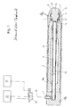
- FIG. 1 is shown in a section along a longitudinal axis of a device for coupling of focused mechanical pressure waves in, for example, the human body.
- a pipe section 1a forms a housing 1 together with a supply air cap 1b which is remote from the body in use and an applicator cap 1c which faces the body in the application.
- the Zu povertykappe 1 b contains a compressed air connection 4 for a pneumatic supply.
- the device is designed as to be held by the hand of an operator device that is connected via the aforementioned pneumatic line 18 to a base station with the drive unit 19 and the compressor 21 and can be placed manually on the patient. It is used to treat soft tissue, especially muscles.
- a guide tube 6 is held via an insert 5, which terminates in the application distal end in the Zu povertykappe 1 b and there communicates with the compressed air connection 4.
- the body-side end of the guide tube 6 terminates in a part of the insert 5, which protrudes into the applicator cap 1c, shortly before the local end of the insert 5 and an inner space 7 in the applicator cap 1 c.
- an impact body 9 is accommodated in the inner space 7, which merges with two radial shoulders into a body-side applicator opening 8 in the application.
- This is supported via an O-ring 10 made of an elastomer on one of the radial shoulders and has for this purpose a flange 11.
- An end 15 of the impact body 9 directed to the far side of the body is supported on the insert 5 via a further O-ring 12, specifically on an end face surrounding the already mentioned end of the insert 5.
- the O-ring 12 is located between this end face and a flange 17 or a shoulder of the impact body 9.
- the applicator opening 8 serves to guide the impact body 9 which is displaceable in the longitudinal direction and fixes it transversely to the longitudinal direction.
- the Axialverschieb sadness is limited by the flexibility of the elastomeric rings 10 and 12 and is at a device operated in air relative to the remaining device significantly above 0.6 mm.
- the impact body 9, which simultaneously forms the applicator to be applied to the skin, can be exchanged by unscrewing the applicator cap 1 c.
- FIG. 1 Impact body 13 in contact with the baffle 9 in contact. This fits (in terms of the guide tube and the substantially cylindrical geometry of the impact member 13) radially with little play.
- the impact member 13 may be due to pressure differences of the air column in the guide tube 6 in front of and behind him (ie in FIG. 1 right and left of the percussion part 13) are reciprocated in the guide tube and in particular to the impact body 9 to be accelerated. For this purpose, it is from a starting position (not shown) in FIG. 1 accelerated by a compressed air surge through the compressed air port 4 and meets with its the impact body 9 facing front surface (in FIG. 1 for clarity's sake not indicated) on the baffle body 9, on a body facing away baffle surface 15 thereof.
- the return movement of the impact member 13 is in addition to a rebound after collision by a backflow of air from a guide tube 6 surrounding the insert 5 stowage chamber 14.
- the air is displaced in the acceleration of the impact member 13 in the direction of the baffle body 9 and so that compresses there. If the solenoid valve 20 in the pneumatic supply line 18 of the compressed air connection 4 switches off the pressure, the impact member 13 is thus moved back to the starting position.
- this can also be done by an additional or alternative pressurization of the storage chamber 14 or other air volume body side of the impact member 13.
- the distal end of the guide tube 6 in the application ends in a magnet holder 17 for the impact part 13.
- the baffle 9 has a rotationally symmetrical cylindrical shape and is limited in the axial direction by the baffle 15 and the somewhat convex coupling surface 16.
- the outer jacket has the already described flange-like structures 11 and 17, which form abutment shoulders for the O-rings 10 and 12.
- an exit-side part of the cylinder geometry is designed with a constant radius and thus axially displaceable in the opening 8.
- Impact body as the impact body 9 drawn here can differ significantly in terms of shape, material and storage. Thus, there are different focusing and non-focussing shapes and different domed exit surfaces in the prior art. Further, various materials are possible, such as stainless steel, titanium, and various ceramics such as silicon nitride and plastics. Finally, different baffles can be stored differently hard and thereby perform different strokes, so perform a different length macroscopic motion in the coupling of the pressure wave.
- FIG. 2 shows in a sectional view of the proximal end of the above-described pressure wave device with the Applikatorkappe 1c, within elastically mounted impact body 9 and the guide tube 6 in an enlarged view.
- a sound-damping sleeve 21 is provided on the outside.
- the sound-absorbing sleeve 21 rests against the housing 1 with webs 22 running around on the inside.
- the webs 22 space the sound-damping sleeve 21 from the housing 1, so that between housing 1 and sound-damping sleeve 21 annular, each separated by a web 22 air volumes 23 are included. Since sound waves are at least partially reflected at interfaces between different media, the sound propagation through the annular air volumes 23 in the radial direction can be damped.
- an elastomer material is provided with regard to a good sound damping, in particular with regard to a good sound absorption, namely silicone rubber.
- a certain minimum thickness is advantageous, which is why the thickness of the sound-absorbing sleeve taken perpendicular to the coupling-in direction 24 is at least 4 mm (and correspondingly greater in the region of a web 22).
- this minimum thickness specification relates primarily to a central region with respect to the coupling-in direction 24, that is to say in any case to a region lying between 30% and 70% of the length of the sound-damping sleeve 21 taken in the coupling-in direction 24.
- the body-facing opening 25 of the sound absorbing sleeve 21 is a Schalldämpfungshülseninnenwand Scheme 26 of the Applikatorkappe 1c, so spaced from the housing 1, so that the Schalldämpfungshülse 21 together with the housing 1 to the open end 25 of the silencer 21 through open Volume limited.
- a therapist can fill a coupling gel before treatment. Limited during treatment then the silencer sleeve 21 on the one hand a lateral distribution of the coupling gel, so it keeps focused on the body to be treated.
- some coupling gel can continuously be dispensed from the volume then serving as the coupling gel reservoir in the course of the treatment, for example when the body-facing end of the sound-damping sleeve 21 and thus within the bounded volume are deformed when pressed against the body, ie the coupling gel is forced out of the coupling gel reservoir ,
- the body-facing opening 25 is tapered by an inwardly directed, circumferential collar 27.
- the body-facing opening of Koppelgelreservoirs is generally reduced, so that the coupling gel in the reservoir remains stored for a longer period of time, so a delivery over a longer treatment period is possible.
- Fig. 3 shows above a Schalldämpfungshülse 21 according to the invention in a section along a longitudinal axis, looking at the bottom left in an oblique view of the body facing away end and looking down right in an oblique view of the body-facing end.
- an opening 32 can be seen, which opens into the coupling reservoir and serves to fill the coupling gel.
- the body-facing opening 25 is tapered by more than 30% by the collar 27 with respect to an outer diameter of the housing, which is 30 mm, and thus measures approximately 19 mm.
- the inner circumferential webs 22 rise from a silencer inner wall by 1 mm inwards.
- FIG. 4 shows a sectional view of the proximal end of a pressure wave device with Applikatorkappe 1c, within elastically mounted impact body 9 (the elastic support is not shown for clarity) and guide tube. 6
- Applicator cap 1c and tube piece 1a form the housing 1, on the outside of which a sound-damping sleeve 21 according to the invention is provided.
- annular air volumes 23 are again arranged, which can dampen the propagation of sound.
- the sound-damping sleeve 21 thus defines, together with the housing 1, a volume open to the open end 25 of the sound-absorbing sleeve 21, into which coupling gel can be introduced.
- the opening 25 is tapered by the inwardly directed collar 27.
- the collar 27 is not designed as an arc rising away from the surface of the applicator cap 1c (delimiting a correspondingly larger volume for the coupling gel), but instead extends substantially parallel to the surface of the applicator cap 1 c.
- the annular air volumes 23 from each other separating web 22 has in the present case an inner circumferential recess 41 a, in which an O-ring 42a is arranged.
- an O-ring 42a is arranged at the end of the sound-damping sleeve 21 facing away from the body to be treated.
- a second circumferential recess 41b with a second O-ring 42b disposed therein.
- the O-rings 42a, b on the one hand already ensure a seal of the interposed air volume 23;
- the O-rings 42a, b for example, facilitate the sliding of the sound attenuation sleeve 21 on the applicator cap 1c and center them on this.
Landscapes
- Health & Medical Sciences (AREA)
- Life Sciences & Earth Sciences (AREA)
- Animal Behavior & Ethology (AREA)
- Veterinary Medicine (AREA)
- Public Health (AREA)
- General Health & Medical Sciences (AREA)
- Rehabilitation Therapy (AREA)
- Physical Education & Sports Medicine (AREA)
- Pain & Pain Management (AREA)
- Epidemiology (AREA)
- Engineering & Computer Science (AREA)
- Surgery (AREA)
- Nuclear Medicine, Radiotherapy & Molecular Imaging (AREA)
- Molecular Biology (AREA)
- Medical Informatics (AREA)
- Heart & Thoracic Surgery (AREA)
- Biomedical Technology (AREA)
- Vascular Medicine (AREA)
- Orthopedic Medicine & Surgery (AREA)
- Mechanical Engineering (AREA)
- Soundproofing, Sound Blocking, And Sound Damping (AREA)
- Percussion Or Vibration Massage (AREA)
- Surgical Instruments (AREA)
Description
- Die vorliegende Erfindung betrifft eine Schalldämpfungshülse zum Aufsetzen auf ein Druckwellengerät zur Behandlung des menschlichen oder tierischen Körpers durch mechanische Druckwellen.
- Geräte zur Behandlung mit mechanischen Druckwellen sind an sich bekannt, insbesondere aus dem Bereich der Lithotripsie. Dort werden mit fokussierten mechanischen Druckwellen Körperkonkremente, etwa Steine im Körpergewebe, zertrümmert. Neben der Erzeugung durch elektrische Entladungen im Wasser sind auch Geräte entwickelt worden, die mechanische Druckwellen durch das Aufeinanderprallen eines beschleunigten Schlagteils und eines Prallkörpers erzeugen. Solche Geräte werden sowohl in der Lithotripsie als auch bei anderen Behandlungen biologischer Körpersubstanzen eingesetzt, wobei insbesondere die Behandlung von Muskelerkrankungen und von Erkrankungen im Übergangsbereich zwischen Muskeln und Knochen sowie Anwendungen im dermatologischen Bereich zu nennen sind.
- In der
DE 10 2004 042 895 A1 ist ein Druckwellengerät mit einem pneumatisch beschleunigten Schlagteil offenbart, welches auf einen Prallkörper prallt und so die Druckwelle erzeugt. Der Prallkörper ist dabei mit einer auf das distale Ende des Druckwellengeräts gesetzten Hygienefolie abgedeckt, die am Gehäuse des Druckwellengeräts gehalten ist und nach der Behandlung ausgetauscht wird, um eine aufwendige Reinigung des Prallkörpers zu vermeiden. - Die
WO 99/08598 A1 - Die
US 6,039,694 A zeigt ein Hygieneset für Ultraschallgeräte, und zwar eine den aktiven Sondenkopf bedeckende Folie und eine diese am Gerät haltende Klammer. In derUS 2006/0173331 A1 sind unterschiedliche Gehäuseformen einer Ultraschallsonde offenbart, wobei ein Griffbereich speziell auf eine zum Teil zur Faust geschlossene Hand abgestimmt ist. - Der vorliegenden Erfindung liegt das technische Problem zugrunde, die Gebrauchseigenschaften von Druckwellengeräten mit Schlagteil und Prallkörper zu verbessern.
- Dieses technische Problem wird erfindungsgemäß durch die Verwendung einer rohrförmigen Schalldämpfungshülse mit offenen Enden gelöst, die auf das Gehäuse eines Druckwellengeräts gesetzt wird und dabei in Einkoppelrichtung eine Länge hat, die mindestens 20% der in derselben Richtung genommenen Länge eines sich innerhalb des Gehäuses erstreckenden Teils des Prallkörpers beträgt.
- Die Erfindung richtet sich gleichermaßen auf ein Druckwellengerät mit beweglichem Schlagteil und Prallkörper, die in einem Gehäuse des Druckwellengeräts montiert sind, wobei an dem Gehäuse außenseitig eine erfindungsgemäße Schalldämpfungshülse vorgesehen ist.
- Bevorzugte Ausgestaltungen der Erfindung sind in den abhängigen Ansprüchen angegeben, wobei in der gesamten Offenbarung nicht im Einzelnen zwischen der Beschreibung der Schalldämpfungshülse, des Druckwellengeräts und dem Verwendungsaspekt der Erfindung unterschieden wird; die Offenbarung ist implizit im Hinblick auf sämtliche Kategorien zu verstehen.
- Die eingangs in Zusammenhang mit der Längenbestimmung genannte Einkoppelrichtung entspricht einer Hauptausbreitungsrichtung der Druckwellen, die sich nach einer Mittelung auch als Schwerpunktrichtung einer Vielzahl Ausbreitungsrichtungen ergeben kann, etwa im Falle sich radial ausbreitender Druckwellen. Wenn der Prallkörper in Abhängigkeit von seiner Lagerung im Gehäuse in Folge eines Aufpralls des Schlagteils ausgelenkt wird, fällt eine Richtungskomponente, typischerweise eine Hauptrichtungskomponente, dieser Auslenkung mit der Hauptausbreitungsrichtung zusammen. Der Übersichtlichkeit halber wird im Folgenden allein von der Einkoppelrichtung gesprochen.
- Die angegebene Mindestlänge der Schalldämpfungshülse ist auf den Prallkörper bezogen, und zwar auf die in Einkoppelrichtung genommene Länge seines innerhalb des Gehäuses angeordneten Teils. Aus dem Gehäuse hervorstehende Teile des Prallkörpers bleiben bei der Längenbetrachtung somit außer Acht, der berücksichtigte Teil des Prallkörpers ist in zur Einkoppelrichtung senkrechten Schnittebenen von Gehäuse umgeben (nicht zwingend vollständig, jedoch vorzugsweise).
- Die Erfinder haben festgestellt, dass es zu einer Geräuschentstehung kommt, selbst wenn eine einer Prallfläche für das Schlagteil entgegensetzte Seite des Prallkörpers an dem zu behandelnden Körperteil anliegt und die Schallausbreitung dadurch eigentlich gedämpft sein sollte. Dies kann zu einer erheblichen Geräuschbelästigung führen, sowohl für den Behandelnden als auch für den Patienten.
- Durch die erfindungsgemäße Schalldämpfungshülse wird die Ausbreitung des sich in Folge des Aufeinanderprallens von Schlagteil und Prallkörper auch quer zur Einkoppelrichtung ausbreitenden Schalls eingedämmt bzw. gedämpft. Es kommt hierbei sowohl eine vielfach als Schalldämmung bezeichnete Behinderung der Schallausbreitung durch Reflexion an Grenzflächen infrage als auch eine oftmals als Schalldämpfung bezeichnete Behinderung der Schallausbreitung durch Absorption von Schall (gleichwohl wird im Kontext dieser Offenbarung der Einfachheit halber allein von Schalldämpfung gesprochen).
- Sofern etwa bei der Beschreibung der Schalldämpfungshülse auf das Druckwellengerät oder einen zu behandelnden Körper Bezug genommen wird, impliziert dies nicht, dass zur Erfüllung des Erfindungsgegenstands die Schalldämpfungshülse auch tatsächlich auf ein Druckwellengerät gesetzt bzw. dieses gegenüber einem Körper entsprechend positioniert werden muss. Es wird vielmehr allein die Geometrie beschrieben, als ob die Schalldämpfungshülse aufgesetzt wäre bzw. ein Körper behandelt würde. "Körper" meint ohne gegenteilige Angabe den Körper des Patienten, also des Behandelten.
- Durch die außenseitig am Gehäuse anliegende Schalldämpfungshülse kann die seitliche Schallausbreitung vorteilhafterweise reduziert werden, wobei erfahrungsgemäß eine gewisse Mindestlänge der Schalldämpfungshülse einzuhalten ist.
- Vorzugsweise ist die Länge der Schalldämpfungshülse in Einkoppelrichtung größer als in dieser Reihenfolge zunehmend bevorzugt 25%, 50%, 75% oder sogar 100% der in derselben Richtung genommenen Länge des sich innerhalb des Gehäuses erstreckenden Teils des Prallkörpers, besonders bevorzugt ist die Länge der Schalldämpfungshülse in Einkoppelrichtung also größer als die in derselben Richtung genommene Länge des sich innerhalb des Gehäuses erstreckenden Teils des Prallkörpers. Im Folgenden wird der Einfachheit halber von der Länge des Prallkörpers gesprochen, wenngleich außer im Falle einer ausdrücklich anderen Angabe die Länge des sich innerhalb des Gehäuses erstreckenden Teils davon gemeint ist. Der Prallkörper kann dann beispielsweise in Bezug auf Richtungen senkrecht zur Einkoppelrichtung vollständig von der Schalldämpfungshülse umgeben sein, sodass der sich vom Prallkörper seitwärts ausbreitende Schall über die gesamte Länge des Prallkörpers gedämpft wird.
- In bevorzugter Ausgestaltung ist die Schalldämpfungshülse für eine solche Anlage an dem Gehäuse ausgelegt, dass sie einen für das Aufprallen des Schlagteils vorgesehenen Bereich des Prallkörpers senkrecht zur Einkoppelrichtung nach außen abdeckt. Eine zur Einkoppelrichtung senkrechte, zu der für das Aufprallen des Schlagteils vorgesehenen Prallfläche des Prallkörpers tangentiale "Ebene des Aufpralls" schneidet also die Schalldämpfungshülse. Besonders bevorzugt schneidet die Ebene des Aufpralls die Schalldämpfungshülse in Bezug auf die Einkoppelrichtung in einem mittigen Bereich, sodass die Ebene des Aufpralls die Schalldämpfungshülse in zwei Teile teilt und sich jede der Hälften auf mindestens 25%, besonders bevorzugt mindestens 35%, der gesamten Schalldämpfungshülsenlänge bemisst.
- Die Schalldämpfungshülse ist als rohrförmiger Körper ausgebildet, der beispielsweise im Falle eines zylindersymmetrischen Gehäuses eine kreisringförmige Querschnittsform haben kann. Die Enden des rohrförmigen Körpers sind offen ausgebildet.
- Eine zu dem Körper hin offene Schalldämpfungshülse kann in Abhängigkeit von ihrer Position auf dem Gehäuse auch eine direkte Anlage des Prallkörpers an den Körper und eine dementsprechend gute Einkopplung der Druckwellen ermöglichen. Die Schalldämpfungshülse wird vorzugsweise so auf dem Gehäuse angeordnet, dass sie auch einen aus dem Gehäuse hervorstehenden Teil des Prallkörpers senkrecht zur Einkoppelrichtung abdeckt, was die von diesem ansonsten (von dem Gehäuse) nicht abgeschirmten Bereich ausgehende Schallausbreitung reduzieren hilft.
- Die Einkopplung kann auch durch das Aufbringen eines Koppelgels verbessert werden, welches dann während der Behandlung als dünner Film zwischen der Einkoppelfläche des Prallkörpers und dem Körper vorliegt. In diesem Zusammenhang kann eine weitere bevorzugte Ausführungsform Vorteile bieten, wenn nämlich die Schalldämpfungshülse im Bereich des dem Körper zugewandten offenen Endes solchermaßen von dem Gehäuse beabstandet ist, dass ein Schalldämpfungshülseninnenwandbereich zusammen mit dem Gehäuse ein Volumen begrenzt. In dieses kann dann nämlich ein Koppelgel eingefüllt werden, vorzugsweise vor einer Behandlung. Weiter bevorzugt ist das von Schalldämpfungshülseninnenwandbereich und
- Gehäuse begrenzte Volumen zu dem offenen Ende der Schalldämpfungshülse hin, also zu dem Körper hin, offen.
- Die Befüllung mit Koppelgel kann durch das zu dem Körper hin offene Ende der Schalldämpfungshülse erfolgen; vorzugsweise ist dazu eine eigene Öffnung vorgesehen, die beispielsweise schräg zur Einkoppelrichtung orientiert von einem Hülsenaußenwandbereich her einen Zugang zu dem Koppelgelreservoir ermöglicht. "Schräg" meint hierbei einen mit der Hauptausbreitungsrichtung eingeschlossenen Winkel (den kleineren von zwei zusammen 180° ergebenden Winkeln) von in dieser Reihenfolge zunehmend bevorzugt mindestens 30°, 45°, 60°, 75°, 85°.
- Über die zusätzliche Öffnung kann dann sowohl ein zu dem Körper hin offenes Koppelgelreservoir als auch ein zu dem Körper hin geschlossenes befüllt werden. Die Koppelgelabgabe kann bei Letzterem etwa erfolgen, indem der Behandelnde auf einen dem Koppelgel entgegengesetzten Hülsenaußenwandbereich drückt und so durch den Druck des Koppelgels ein temporäres Öffnen des ansonsten geschlossenen Volumens bewirkt, etwa indem das Koppelgel zwischen einem ansonsten an dem Gehäuse anliegenden Kragen einer Schalldämpfungshülse aus Elastomermaterial und dem Gehäuse hindurchgedrückt wird.
- Das Befüllen eines zu dem Körper hin offenen Volumens über eine zusätzliche Öffnung kann den Vorteil bieten, dass dabei Luft durch die dem Körper zugewandte Öffnung entweichen, das Reservoir also im Wesentlichen luftblasenfrei befüllt werden kann. In diesem Zusammenhang könnte eine zusätzliche Öffnung auch der Entlüftung dienen.
- Die Erfinder haben festgestellt, dass das Koppelgel während einer Behandlung seitlich weggeschoben und somit üblicherweise innerhalb kurzer Zeit über die Haut verteilt wird. Dies hat zur Folge, dass ein behandelnder Arzt oder Therapeut das Gel zwischenzeitlich immer wieder zurückschieben oder neues Gel auftragen muss; in beiden Fällen ist die Behandlung beeinträchtigt bzw. muss diese unterbrochen werden.
- Indem erfindungsgemäß eine Schalldämpfungshülse mit einem zu dem Körper hin offenen Reservoir vorgesehen wird, kann, wenn während der Behandlung das körperzugewandte offene Ende der Schalldämpfungshülse an dem Körper anliegt, der von dem Gehäuse beabstandete Innenwandbereich ein seitliches Wegschieben des Koppelgels zumindest teilweise unterbinden. Mit anderen Worten ist das ansonsten offene Volumen dann von der Haut des Patienten begrenzt, wird das Koppelgel während der Behandlung also in einem (innerhalb gewisser Grenzen) geschlossenen Volumen beisammengehalten. Es kann also beispielsweise weniger Koppelgel vorgesehen werden, was etwa in Kostenhinsicht vorteilhaft ist, bzw. kann die Aufmerksamkeit des Behandelnden auf die eigentliche Behandlung gerichtet bleiben.
- Eine weitere Ausführungsform betrifft einen nach innen gerichteten umlaufenden Kragen, durch den die dem Körper zugewandte Öffnung der Schalldämpfungshülse verjüngt ist. Ein solcher Kragen kann beispielsweise beim Aufsetzen der Schalldämpfungshülse als Anschlag dienen und so eine Relativposition von Schalldämpfungshülse und Druckwellengerät vorgeben. Besonders bevorzugt wird der Kragen jedoch in Verbindung mit dem von dem Gehäuse beabstandeten Innenwandbereich, also dem Koppelgelreservoir, vorgesehen und kann so etwa das Koppelgel an dem offenen Ende in Richtung der Einkoppelfläche des Prallkörpers lenken. Der Kragen kann auch in der zuvor beschriebenen Weise an dem Gehäuse anliegen und das Koppelgelreservoir so zu dem Körper hin verschließen (und nur unter Druck öffnen und Koppelgel freigeben); vorzugsweise ist das Koppelgelreservoir jedoch auch im Falle eines vorgesehenen Kragens zu dem Körper hin offen, auch wenn kein Koppelgel gegen den Kragen drückt.
- Wird beispielsweise eine Schalldämpfungshülse aus einem Elastomermaterial vorgesehen, kann das Volumen des Koppelgelreservoirs beim Andrücken der Schalldämpfungshülse an den zu behandelnden Körper verändert und so auch ein Herausdrücken des Koppelgels bewirkt werden. Dies kann etwa auch durch eine Relativverschiebung zwischen Schalldämpfungshülse (also des vom Gehäuse beabstandeten Bereichs davon) und Gehäuse senkrecht zur Einkoppelrichtung erfolgen.
- Der Durchmesser der durch den Kragen verjüngten Öffnung ist vorzugsweise um mindestens 10%, in dieser Reihenfolge zunehmend bevorzugt um mindestens 15 %, 20 %, 25 %, 30%, kleiner als der Innendurchmesser des für die Anlage am Gehäuse vorgesehenen Bereichs der Schalldämpfungshülse (also auch gleichermaßen kleiner als der Außendurchmesser des Gehäuses). Wenngleich für Prallkörper, Gehäuse und Schalldämpfungshülse eine zylindrische Geometrie bevorzugt ist, sollen auch Ausführungsformen mit anderen Querschnittsformen umfasst sein und ist in einem solchen Fall die Durchmesserangabe auf den minimalen Durchmesser bezogen, also beispielsweise im Falle eines quadratischen Querschnitts auf die Kantenlänge.
- Im Hinblick auf gute Schalldämpfungseigenschaften, insbesondere hinsichtlich einer Absorption von Schall, ist für die Schalldämpfungshülse ein Material mit einem Elastizitätsmodul von weniger als 10 GPa, in dieser Reihenfolge zunehmend bevorzugt von weniger als 5, 3, 2, 1 GPa, bevorzugt. Es kann beispielsweise eine Schalldämpfungshülse aus einem Elastomermaterial, etwa einem insbesondere auch synthetischen Kautschukmaterial, vorgesehen werden.
- Im Hinblick auf die Schallabsorption ist auch eine gewisse Mindestdicke, gemessen in einer Richtung senkrecht zur Einkoppelrichtung, bevorzugt; die Schalldämpfungshülse hat in dieser Reihenfolge zunehmend bevorzugt eine Dicke von mindestens 1, 2, 3, 4 mm.
- Die Erfinder haben festgestellt, dass die Schalldämpfungseigenschaften ferner durch in der bzw. von der Schalldämpfungshülse eingeschlossene Luftvolumina verbessert werden können, weil ein Luftvolumen als Unstetigkeitsstelle die Schalltransmission verringern helfen kann.
- Hier hat sich eine Beabstandung der Schalldämpfungshülse von dem Gehäuse als vorteilhaft erwiesen, und zwar durch einen an der Schalldämpfungshülse innenseitig vorgesehenen Abstandshalter. So kann einerseits in einem Pfad der Schallausbreitung ein Luftvolumen zur Verfügung gestellt werden; andererseits kann ein solcher innenseitig vorgesehener Abstandshalter auch einfach hergestellt werden, etwa in einem formenden Verfahren in demselben Fertigungsschritt wie die Schalldämpfungshülse.
- In weiterer Ausgestaltung ist der Abstandshalter als innenseitiger, vorzugsweise umlaufender Steg ausgebildet, sodass beispielsweise in Bezug auf die Einkoppelrichtung beidseits des Stegs ringförmige Luftvolumina zwischen Schalldämpfungshülse und Gehäuse eingeschlossen sein können. Die Angabe "ringförmig" bezieht sich hierbei auf eine zur Einkoppelrichtung senkrechte Schnittebene, wobei eine Kreisringform bevorzugt ist. Es können sich dann also beispielsweise mehrere ringförmige bzw. kreisringförmige Luftvolumina jeweils über eine bestimmte Länge in Einkoppelrichtung erstrecken und in Einkoppelrichtung direkt aufeinanderfolgende Luftvolumina jeweils durch einen umlaufenden Steg voneinander getrennt sein.
- Mit einer Mehrzahl solcher durch Stege voneinander getrennten Luftvolumina kann nahezu über die gesamte Länge der Schalldämpfungshülse ein Luftvolumen in einem Pfad der Schallausbreitung vorgesehen werden und liegt die Schalldämpfungshülse gleichzeitig mit der Mehrzahl Stege an dem Gehäuse an, ist also hinreichend gegen ein Verrutschen gesichert.
- In bevorzugter Ausgestaltung ist eine Schalldämpfungshülse mit einem Elastomerkörper vorgesehen, der zwischen Schalldämpfungshülse und Gehäuse angeordnet wird. Generell kann ein solcher Elastomerkörper beispielsweise die Schalldämpfungshülse von dem Gehäuse beabstanden und etwa in Verbindung mit einem weiteren Elastomerkörper ein in den vorstehenden Absätzen beschriebenes Luftvolumen begrenzen; bevorzugt ist gleichwohl ein einstückig mit der Schalldämpfungshülse ausgebildeter Abstandshalter.
- Schalldämpfungshülse und Elastomerkörper sind hingegen mehrteilig, also nicht als einstückiger Körper ausgebildet. Vorzugsweise ist der Elastomerkörper ein umlaufender Ring, etwa ein Dichtring mit beispielsweise kreisringförmigem Querschnittsprofil (O-Ring). Für den Elastomerkörper kann zum Beispiel auch ein gegenüber jenem der Schalldämpfungshülse weicheres Material vorgesehen werden, dieses kann beispielsweise einen um jeweils mindestens 10 %, 25 % oder auch 50 % geringeren Elastizitätsmodul als das für die Schalldämpfungshülse vorgesehene Material haben. Der Elastomerkörper kann Gehäuse und Schalldämpfungshülse so beispielsweise auch mechanisch entkoppeln, was hinsichtlich der Schalldämpfung Vorteile bieten kann.
- Vorzugsweise wird der Elastomerkörper in einer innenseitig der Schalldämpfungshülse, dem Gehäuse zugewandten Ausnehmung angeordnet, die den Elastomerkörper beispielsweise auch beim Aufschieben der Schalldämpfungshülse in Position halten kann; andererseits kann beispielsweise ein O-Ring das Aufschieben auch erleichtern. Über den Elastomerkörper kann die Schalldämpfungshülse beispielsweise auch zentriert auf dem Gehäuse gelagert sein.
- Wenngleich im Allgemeinen auch der Elastomerkörper selbst die Schalldämpfungshülse von dem Gehäuse beabstanden kann, ist ein einstückig mit der Schalldämpfungshülse ausgebildeter Steg bevorzugt, in dem besonders bevorzugt eine Ausnehmung vorgesehen ist; in dieser ist der dann an dem Gehäuse anliegende Elastomerkörper angeordnet (die Schalldämpfungshülse wird dann gegebenenfalls durch Steg und Elastomerkörper von dem Gehäuse beabstandet werden, wobei der Anteil des Elastomerkörpers an der überbrückten Distanz üblicherweise geringer sein wird). Der Elastomerkörper kann also vorteilhafterweise ein vorstehend beschriebenes, vorzugsweise ringförmiges und besonders bevorzugt auch von einem Steg begrenztes Luftvolumen abdichten.
- Die Geräuschentwicklung kann auf das Aufeinanderprallen von beweglichem Schlagteil und üblicherweise elastisch gelagertem Prallkörper zurückgeführt werden. Dabei kommt es während einer Behandlung typischerweise nicht nur zu einem solchen Aufprall, sondern prallen Schlagteil und Prallkörper wiederholt und vielfach aufeinander. Hierzu kann das Schlagteil beispielsweise auf einer Kreisbahn bewegt werden und mit jeder Umdrehung den Prallkörper streifen. Das Schlagteil kann beispielsweise auch auf einer linearen Bahn beschleunigt werden, etwa elektromagnetisch oder mit einem Federmechanismus.
- Generell ist ein pneumatischer Antrieb, mit dem das Schlagteil bewegbar ist, bevorzugt; es könnte also beispielsweise eine Achse, mit der das Schlagteil verbunden ist, mit Druckluft in Rotation versetzt und das Schlagteil so auf einer Kreisbahn bewegt werden.
- Besonders bevorzugt ist das Schlagteil jedoch in einem sich in Einkoppelrichtung erstreckenden Führungsrohr geführt, "passt" das Schlagteil also in Richtungen senkrecht zur Einkoppelrichtung mit beispielsweise geringem Spiel in das Führungsrohr und kann durch einen pneumatischen Druckpuls des pneumatischen Antriebs in Einkoppelrichtung bewegt werden.
- Die Erfindung richtet sich auch auf die Verwendung einer vorstehend beschriebenen Schalldämpfungshülse zum Aufsetzen auf ein solches Druckwellengerät. Dabei kann in bevorzugter Ausgestaltung die Schalldämpfungshülse auch als Einwegbauteil vorgesehen sein, das vor einer Behandlung eines weiteren Patienten gegen eine unbenutzte Schalldämpfungshülse ausgetauscht wird.
- Fig. 1
- zeigt ein an sich vorbekanntes pneumatisch betriebenes Druckwellengerät mit Prallkörper und Schlagteil in einem Längsschnitt.
- Fig. 2
- zeigt das dem Körper zugewandte Ende eines Druckwellengeräts gemäß
Figur 1 mit dem Prallkörper in vergrößerter Darstellung, wobei eine erfindungsgemäße Schalldämpfungshülse aufgesetzt ist. - Fig. 3
- zeigt verschiedene Ansichten einer erfindungsgemäßen Schalldämpfungshülse.
- Fig. 4
- illustriert analog zu
Figur 2 eine auf das dem Körper zugewandte Ende eines Druckwellengeräts aufgesetzte erfindungsgemäße Schalldämpfungshülse. - In
Figur 1 ist in einem Schnitt entlang einer Längsachse ein Gerät zur Einkopplung von fokussierten mechanischen Druckwellen in beispielsweise den menschlichen Körper dargestellt. Ein Rohrstück 1a bildet gemeinsam mit einer in der Anwendung körperabgewandten Zuluftkappe 1 b und einer in der Anwendung körperzugewandten Applikatorkappe 1c ein Gehäuse 1. - Die Zuluftkappe 1 b enthält einen Druckluftanschluss 4 für eine pneumatische Versorgung. In an sich bekannter Weise ist an diesen Druckluftanschluss 4 über eine pneumatische Versorgungsleitung 18 ein von einer Ansteuereinheit 19 gesteuertes Ventil 20, insbesondere Magnetventil, angeschlossen, das in einem gleich bleibenden iterativen Takt zwischen etwa 1 Hz und 50 Hz Druckluftpulse über den Druckluftanschluss einkoppelt.
- Das Gerät ist als mit der Hand einer Bedienungsperson zu haltendes Gerät ausgebildet, das über die erwähnte Pneumatikleitung 18 an eine Basisstation mit der Ansteuereinheit 19 und dem Kompressor 21 angeschlossen ist und auf den Patienten manuell aufgesetzt werden kann. Es dient zur Behandlung von Weichgewebe, insbesondere Muskeln.
- In dem Gehäuse 1 ist über einen Einsatz 5 ein Führungsrohr 6 gehalten, dessen bei der Anwendung körperfernes Ende in der Zuluftkappe 1 b endet und dort mit dem Druckluftanschluss 4 kommuniziert. Das in der Anwendung körperseitige Ende des Führungsrohres 6 endet in einem Teil des Einsatzes 5, der in die Applikatorkappe 1c hineinragt, und zwar kurz vor dem dortigen Ende des Einsatzes 5 und einem Innenraum 7 in der Applikatorkappe 1 c.
- In dem Innenraum 7, der mit zwei radialen Schultern in eine in der Anwendung körperseitige Applikatoröffnung 8 übergeht, ist ein Prallkörper 9 aufgenommen. Dieser stützt sich über einen O-Ring 10 aus einem Elastomer an einer der radialen Schultern ab und weist hierzu einen Flansch 11 auf. Ein zur körperfernen Seite gerichtetes Ende 15 des Prallkörpers 9 stützt sich über einen weiteren O-Ring 12 an dem Einsatz 5 ab, und zwar an einer das bereits erwähnte Ende des Einsatzes 5 umgebenden Stirnfläche. Dabei liegt der O-Ring 12 zwischen dieser Stirnfläche und einem Flansch 17 bzw. einer Schulter des Prallkörpers 9. Die Applikatoröffnung 8 dient dabei zu einer in der Längsrichtung verschiebbaren Führung des Prallkörpers 9 und fixiert diesen quer zur Längsrichtung. Die Axialverschiebbarkeit ist durch die Nachgiebigkeit der Elastomerringe 10 und 12 begrenzt und liegt bei einem in Luft betriebenen Gerät relativ zum Restgerät deutlich über 0,6 mm.
- Der Prallkörper 9, der hier gleichzeitig den auf die Haut aufzusetzenden Applikator bildet, ist durch Abschrauben der Applikatorkappe 1 c austauschbar.
- In dem angrenzenden Bereich des Führungsrohres 6 ist ein in
Figur 1 mit dem Prallkörper 9 in Kontakt stehendes Schlagteil 13 eingesetzt. Dieses passt (in Bezug auf das Führungsrohr und die im Wesentlichen zylindrische Geometrie des Schlagteils 13) radial mit geringem Spiel. Das Schlagteil 13 kann durch Druckunterschiede der Luftsäule in dem Führungsrohr 6 vor und hinter ihm (d. h. inFigur 1 rechts und links des Schlagteils 13) in dem Führungsrohr hin- und herbewegt werden und insbesondere auf den Prallkörper 9 zu beschleunigt werden. Hierzu wird es aus einer Ausgangsposition (nicht gezeigt) inFigur 1 links durch einen Druckluftstoß durch den Druckluftanschluss 4 beschleunigt und trifft mit seiner dem Prallkörper 9 zugewandten Frontfläche (inFigur 1 der Übersichtlichkeit halber nicht bezeichnet) auf den Prallkörper 9 auf, und zwar auf eine körperabgewandte Prallfläche 15 davon. - Die Rückbewegung des Schlagteils 13 erfolgt zusätzlich zu einem Zurückprallen nach der Kollision durch ein Rückströmen der Luft aus einer das Führungsrohr 6 innerhalb des Einsatzes 5 umgebenden Staukammer 14. In diese wird die Luft bei der Beschleunigung des Schlagteils 13 in Richtung zu dem Prallkörper 9 verdrängt und damit dort komprimiert. Wenn das Magnetventil 20 in der Pneumatikzuleitung 18 des Druckluftanschlusses 4 den Druck wegschaltet, wird das Schlagteil 13 damit in die Ausgangsstellung zurückbewegt. Dies kann natürlich auch durch eine zusätzliche oder alternative Druckbeaufschlagung der Staukammer 14 oder eines anderen Luftvolumens körperseitig von dem Schlagteil 13 erfolgen. Das in der Anwendung körperferne Ende des Führungsrohres 6 endet in einem Magnethalter 17 für das Schlagteil 13.
- Der Prallkörper 9 hat eine rotationssymmetrische Zylinderform und ist in axialer Richtung durch die Prallfläche 15 und die etwas konvexe Einkoppelfläche 16 begrenzt. Der Außenmantel weist die bereits beschriebenen flanschartigen Strukturen 11 und 17 auf, die Anlageschultern für die O-Ringe 10 und 12 bilden. Im Übrigen ist ein austrittsseitiger Teil der Zylindergeometrie mit konstantem Radius gestaltet und damit in der Öffnung 8 axial verschiebbar.
- Prallkörper wie der hier gezeichnete Prallkörper 9 können sich hinsichtlich Form, Material und Lagerung erheblich unterschieden. So gibt es unterschiedliche fokussierende und nicht fokussierende Formen und verschiedene gewölbte Austrittsflächen im Stand der Technik. Ferner kommen verschiedene Materialien in Betracht, etwa Edelstahl, Titan, und verschiedene Keramiken wie Siliziumnitrid sowie Kunststoffe. Schließlich können verschiedene Prallkörper unterschiedlich hart gelagert sein und dabei unterschiedliche Hübe ausführen, also eine unterschiedlich lange makroskopische Bewegung bei der Einkopplung der Druckwelle durchführen.
-
Figur 2 zeigt in einer Schnittdarstellung das körpernahe Ende des eben erläuterten Druckwellengeräts mit der Applikatorkappe 1c, dem innerhalb elastisch gelagerten Prallkörper 9 und dem Führungsrohr 6 in vergrößerter Darstellung. An dem mit durch Applikatorkappe 1c und Rohrstück 1a gebildeten Gehäuse 1 ist außenseitig eine erfindungsgemäße Schalldämpfungshülse 21 vorgesehen. - Die Schalldämpfungshülse 21 liegt mit innenseitig umlaufenden Stegen 22 an dem Gehäuse 1 an. Die Stege 22 beabstanden die Schalldämpfungshülse 21 von dem Gehäuse 1, sodass zwischen Gehäuse 1 und Schalldämpfungshülse 21 ringförmige, jeweils durch einen Steg 22 voneinander getrennte Luftvolumina 23 eingeschlossen sind. Da Schallwellen an Grenzflächen zwischen verschiedenen Medien zumindest teilweise reflektiert werden, kann die Schallausbreitung durch die ringförmigen Luftvolumina 23 in radialer Richtung gedämpft werden.
- Für die Schalldämpfungshülse 21 ist hinsichtlich einer guten Schalldämpfung, insbesondere im Hinblick auf eine gute Schallabsorption, ein Elastomermaterial vorgesehen, nämlich Silikonkautschuk. Ferner ist in diesem Zusammenhang eine gewisse Mindestdicke vorteilhaft, weswegen die senkrecht zur Einkoppelrichtung 24 genommene Dicke der Schalldämpfungshülse mindestens 4 mm beträgt (und im Bereich eines Stegs 22 entsprechend größer ist). Diese Mindestdickenangabe bezieht sich dabei vorrangig auf einen in Bezug auf die Einkoppelrichtung 24 mittigen Bereich, also jedenfalls auf einen zwischen 30 % und 70% der in Einkoppelrichtung 24 genommenen Länge der Schalldämpfungshülse 21 liegenden Bereich.
- Im Bereich einer endseitigen, dem Körper zugewandten Öffnung 25 der Schalldämpfungshülse 21 ist ein Schalldämpfungshülseninnenwandbereich 26 von der Applikatorkappe 1c, also von dem Gehäuse 1, beabstandet, sodass die Schalldämpfungshülse 21 gemeinsam mit dem Gehäuse 1 ein zu dem offenen Ende 25 der Schalldämpfungshülse 21 hin offenes Volumen begrenzt. In dieses kann ein Therapeut vor einer Behandlung ein Koppelgel einfüllen. Während der Behandlung begrenzt dann die Schalldämpfungshülse 21 einerseits eine seitliche Verteilung des Koppelgels, hält es also auf die zu behandelnde Stelle konzentriert. Andererseits kann aus dem dann als Koppelgelreservoir dienenden Volumen im Zuge der Behandlung fortwährend auch etwas Koppelgel abgegeben werden, etwa wenn das körperzugewandte Ende der Schalldämpfungshülse 21 und damit das innerhalb begrenzte Volumen beim Andrücken an den Körper verformt werden, das Koppelgel also aus dem Koppelgelreservoir herausgedrückt wird.
- Um das Koppelgel in Richtung der Einkoppelfläche 16 des Prallkörpers 9 zu lenken, ist die körperzugewandte Öffnung 25 durch einen nach innen gerichteten, umlaufenden Kragen 27 verjüngt. Durch den Kragen 27 wird die körperzugewandte Öffnung des Koppelgelreservoirs generell verringert, sodass das Koppelgel in dem Reservoir auch für eine längere Zeitdauer bevorratet bleibt, also eine Abgabe über einen längeren Behandlungszeitraum möglich ist.
-
Fig. 3 zeigt oben eine erfindungsgemäße Schalldämpfungshülse 21 in einem Schnitt entlang einer Längsachse, links unten in einer Schrägansicht auf das körperabgewandte Ende blickend und rechts unten in einer Schrägansicht auf das körperzugewandte Ende blickend. In der zuletzt genannten Schrägansicht ist eine Öffnung 32 zu erkennen, die in das Koppelreservoir mündet und zum Einfüllen des Koppelgels dient. - Die körperzugewandte Öffnung 25 ist durch den Kragen 27 gegenüber einem Au-ßendurchmesser des Gehäuses, der 30 mm beträgt, um mehr als 30% verjüngt und bemisst sich somit auf etwa 19 mm.
- Die innenseitig umlaufenden Stege 22 erheben sich von einer Schalldämpfungshülseninnenwand um 1 mm nach innen. Die dann von dem Gehäuse 1 und der Schalldämpfungshülse 21 eingeschlossenen, ringförmigen Luftvolumina 23 haben somit senkrecht zur Einkoppelrichtung 24 eine Dicke von 1 mm.
-
Figur 4 zeigt in einer Schnittdarstellung das körpernahe Ende eines Druckwellengeräts mit Applikatorkappe 1c, innerhalb elastisch gelagertem Prallkörper 9 (die elastische Lagerung ist der Übersichtlichkeit halber nicht dargestellt) und Führungsrohr 6. - Applikatorkappe 1c und Rohrstück 1a bilden das Gehäuse 1, an dem außenseitig eine erfindungsgemäße Schalldämpfungshülse 21 vorgesehen ist.
- Dabei sind zwischen Applikatorkappe 1c und Schalldämpfungshülse 21 wiederum ringförmige Luftvolumina 23 angeordnet, welche die Schallausbreitung dämpfen können. Im Bereich der dem Körper zugewandten Öffnung 25 der Schalldämpfungshülse 21 ist diese ferner analog jener aus
Figur 2 von dem Gehäuse 1 beabstandet, begrenzt die Schalldämpfungshülse 21 also gemeinsam mit dem Gehäuse 1 ein zu dem offenen Ende 25 der Schalldämpfungshülse 21 hin offenes Volumen, in welches Koppelgel eingefüllt werden kann. - Um das Koppelgel auf den Kontaktbereich zwischen Prallkörper 9 und zu behandelndem Körper zu konzentrieren, ist die Öffnung 25 durch den nach innen gerichteten Kragen 27 verjüngt. Im Gegensatz zu der anhand von
Figur 2 erläuterten Schalldämpfungshülse 21 ist der Kragen 27 vorliegend nicht als sich zunächst von der Oberfläche der Applikatorkappe 1c weg erhebender Bogen (der ein entsprechend größeres Volumen für das Koppelgel begrenzt) ausgebildet, sondern erstreckt sich der Kragen im Wesentlichen parallel zur Oberfläche der Applikatorkappe 1 c. - In
Figur 4 erstreckt sich der Kragen in Einkoppelrichtung 24 nicht ganz bis zu dem körperzugewandten Ende des Prallkörpers 9; dies wäre jedoch auch möglich, sodass der Kragen analog zu der inFigur 2 gezeigten Schalldämpfungshülse 21 bündig mit dem Prallkörper abschließen oder diesen in Einkoppelrichtung sogar auch überragen könnte. Ferner könnte sich die Schalldämpfungshülse (was in der Figur gleichermaßen nicht gezeigt ist) auch in der entgegengesetzten Richtung weiter erstrecken und insbesondere den Kontaktbereich von Applikatorkappe 1c und Rohrelement 1a vollständig überdecken, also in der Figur zumindest noch die Nut ausfüllen oder sich auch noch weiter über das Gehäuse 1 erstrecken (vom Körper weg). - Der die ringförmigen Luftvolumina 23 voneinander trennende Steg 22 weist vorliegend eine innenseitig umlaufende Ausnehmung 41 a auf, in welcher ein O-Ring 42a angeordnet ist. An dem dem zu behandelnden Körper abgewandten Ende der Schalldämpfungshülse 21 ist ferner eine zweite innenseitig umlaufende Ausnehmung 41 b mit darin angeordnetem zweiten O-Ring 42b vorgesehen. Die O-Ringe 42a, b können einerseits schon eine Abdichtung des dazwischen angeordneten Luftvolumens 23 sicherstellen; andererseits können die O-Ringe 42a, b beispielsweise auch das Aufschieben der Schalldämpfungshülse 21 auf die Applikatorkappe 1c erleichtern und sie auf dieser zentrieren.
Claims (14)
- Gerät zur Behandlung des menschlichen oder tierischen Körpers durch mechanische Druckwellen mit
einem beweglichen Schlagteil (13),
einem Prallkörper (9), wobei die Druckwellen durch Beschleunigen und Aufprallen des Schlagteils (13) auf den Prallkörper (9) erzeugbar und in den Körper einkoppelbar sind,
und einem Gehäuse (1), in dem das Schlagteil (13) und der Prallkörper (9) montiert sind, und
einer Schalldämpfungshülse (21),
wobei die Schalldämpfungshülse (21) für eine Anlage außenseitig an dem Gehäuse (1) ausgelegt ist und dabei in Einkoppelrichtung (24) eine Länge hat, die mindestens 20% der in derselben Richtung genommenen Länge eines sich innerhalb des Gehäuses (1) erstreckenden Teils des Prallkörpers (9) beträgt,
dadurch gekennzeichnet, dass
die Schalldämpfungshülse (21) als rohrförmiger Körper mit offenen Enden ausgebildet ist. - Gerät nach Anspruch 1, bei welchem die Schalldämpfungshülse (21) für eine solche Anlage an dem Gehäuse (1) ausgelegt ist, dass sie einen für das Aufprallen des Schlagteils (13) vorgesehenen Bereich des Prallkörpers (9) senkrecht zur Einkoppelrichtung (24) nach außen abdeckt.
- Gerät nach Anspruch 1 oder 2, bei welchem die Schalldämpfungshülse (21) dazu ausgelegt ist, im Bereich eines dem Körper zugewandten offenen Endes (25) solchermaßen von dem Gehäuse (1) beabstandet zu sein, dass ein Schalldämpfungshülseninnenwandbereich (26) zusammen mit dem Gehäuse (1) ein Volumen begrenzt, in welches ein Koppelgel einfüllbar ist, vorzugsweise ein zu dem offenen Ende der Schalldämpfungshülse (21) hin offenes Volumen.
- Gerät nach einem der vorstehenden Ansprüche, bei welchem ein dem Körper zugewandtes offenes Ende (25) der Schalldämpfungshülse (21) durch einen nach innen gerichteten umlaufenden Kragen (27) verjüngt ist.
- Gerät nach einem der vorstehenden Ansprüche, bei welchem an der Schalldämpfungshülse (21) innenseitig ein Abstandshalter (22) vorgesehen ist, der dazu ausgelegt ist, die Schalldämpfungshülse (21) von dem Gehäuse (1) zu beabstanden und vorzugsweise als innenseitiger, besonders bevorzugt umlaufender Steg (22) ausgebildet ist.
- Gerät nach Anspruch 6, bei welchem die Schalldämpfungshülse (21) dazu ausgelegt ist, ein geschlossenes, zwischen dem Gehäuse (1) und der Schalldämpfungshülse (21) angeordnetes Luftvolumen (23), vorzugsweise ein ringförmiges Luftvolumen (23), zu begrenzen.
- Gerät nach einem der vorstehenden Ansprüche, bei welchem die Schalldämpfungshülse (21) einen Elastomerkörper (42a, b) umfasst und für eine solche Anlage an dem Gehäuse (1) ausgelegt ist, dass der Elastomerkörper (42a, b) zwischen dem Gehäuse (1) und der Schalldämpfungshülse (21) angeordnet ist.
- Gerät nach einem der vorstehenden Ansprüche, bei welchem die Schalldämpfungshülse (21) aus einem Elastomermaterial vorgesehen ist.
- Gerät nach einem der vorstehenden Ansprüche, bei welchem die Schalldämpfungshülse (21) bei Raumtemperatur einen Elastizitätsmodul von weniger als 10 GPa, vorzugsweise weniger als 5 GPa hat.
- Gerät nach einem der vorstehenden Ansprüche, bei welchem die Schalldämpfungshülse (21) eine senkrecht zur Einkoppelrichtung (24) genommene Dicke von mindestens 1 mm hat.
- Verwendung einer Schalldämpfungshülse (21) zum Aufsetzen auf ein Gerät, welches Gerät
einen beweglichen Schlagteil (13),
einen Prallkörper (9), wobei die Druckwellen durch Beschleunigen und Aufprallen des Schlagteils (13) auf den Prallkörper (9) erzeugbar und in den Körper einkoppelbar sind,
und ein Gehäuse (1), in dem das Schlagteil (13) und der Prallkörper (9) montiert sind, umfasst,
wobei die Schalldämpfungshülse (21) außenseitig an dem Gehäuse (1) anliegt und dabei in Einkoppelrichtung (24) eine Länge hat, die mindestens 20% der in derselben Richtung genommenen Länge eines sich innerhalb des Gehäuses (1) erstreckenden Teils des Prallkörpers (9) beträgt,
dadurch gekennzeichnet, dass
die Schalldämpfungshülse (21) als rohrförmiger Körper mit offenen Enden ausgebildet ist. - Verwendung nach Anspruch 11 für ein Gerät nach einem der Ansprüche 1 bis 10.
- Verwendung nach Anspruch 11 oder 12, wobei die Schalldämpfungshülse (21) vor einer Behandlung eines weiteren Patienten gegen eine unbenutzte Schalldämpfungshülse (21) ausgetauscht wird.
- Verwendung nach einem der Ansprüche 11 bis 13 eines Geräts nach Anspruch 3, wobei vor einer Behandlung in das von Schalldämpfungshülse (21) und Gehäuse (1) begrenzte Volumen ein Koppelgel eingefüllt wird.
Applications Claiming Priority (1)
| Application Number | Priority Date | Filing Date | Title |
|---|---|---|---|
| DE201120101571 DE202011101571U1 (de) | 2011-05-30 | 2011-05-30 | Schalldämpfungshülse zum Aufsetzen auf ein Druckwellengerät |
Publications (2)
| Publication Number | Publication Date |
|---|---|
| EP2529679A1 EP2529679A1 (de) | 2012-12-05 |
| EP2529679B1 true EP2529679B1 (de) | 2014-05-14 |
Family
ID=46318860
Family Applications (1)
| Application Number | Title | Priority Date | Filing Date |
|---|---|---|---|
| EP20120170016 Active EP2529679B1 (de) | 2011-05-30 | 2012-05-30 | Schalldämpfungshülse zum Aufsetzen auf ein Druckwellengerät |
Country Status (2)
| Country | Link |
|---|---|
| EP (1) | EP2529679B1 (de) |
| DE (1) | DE202011101571U1 (de) |
Cited By (1)
| Publication number | Priority date | Publication date | Assignee | Title |
|---|---|---|---|---|
| EP4570312A4 (de) * | 2023-10-11 | 2026-05-13 | K1Med Global Inc | Kombinierte extrakorporale stosswellen- und funkfrequenzbehandlungsvorrichtung mit anti-cellulite-funktion |
Families Citing this family (11)
| Publication number | Priority date | Publication date | Assignee | Title |
|---|---|---|---|---|
| US12220380B2 (en) | 2015-09-30 | 2025-02-11 | Btl Medical Solutions A.S. | Methods and devices for tissue treatment using mechanical stimulation and electromagnetic field |
| US11484724B2 (en) | 2015-09-30 | 2022-11-01 | Btl Medical Solutions A.S. | Methods and devices for tissue treatment using mechanical stimulation and electromagnetic field |
| CN107502719B (zh) * | 2017-07-11 | 2023-03-28 | 沈阳理工大学 | 一种超声波冲击消应器的隔音降噪装置 |
| DE102018205574A1 (de) * | 2018-04-12 | 2019-10-17 | Zimmer Medizinsysteme Gmbh | STOßWELLENGENERATOR, HANDSTÜCK FÜR EINE STOßWELLENTHERAPIEVORRICHTUNG UND STOßWELLENTHERAPIEVORRICHTUNG |
| CN110403810B (zh) * | 2019-07-08 | 2021-12-03 | 李卫 | 一种气压式冲击波治疗仪的气压输出控制方法 |
| ES3055165T3 (en) | 2022-08-25 | 2026-02-10 | Storz Medical Ag | Pressure wave device with double valve device |
| PT4327761T (pt) | 2022-08-25 | 2025-12-11 | Storz Medical Ag | Aparelho de ondas de pressão com dispositivo de válvula dupla |
| ES3052404T3 (en) | 2022-08-25 | 2026-01-07 | Storz Medical Ag | Pressure wave device with double valve device |
| ES3055389T3 (en) | 2022-08-25 | 2026-02-11 | Storz Medical Ag | Pressure wave device with double valve device |
| DE102022133521B3 (de) * | 2022-12-15 | 2024-02-29 | Karl Storz Se & Co. Kg | Haltevorrichtung für eine Lithotripsievorrichtung und Lithotripsievorrichtung zum Zertrümmern von Körpersteinen |
| DE102022133520B3 (de) * | 2022-12-15 | 2024-01-11 | Karl Storz Se & Co. Kg | Haltevorrichtung für eine Lithotripsievorrichtung zum Zertrümmern von Körpersteinen und Lithotripsievorrichtung |
Family Cites Families (5)
| Publication number | Priority date | Publication date | Assignee | Title |
|---|---|---|---|---|
| CA2300817A1 (en) * | 1997-08-19 | 1999-02-25 | John D. Mendlein | Ultrasonic transmission films and devices, particularly for hygienic transducer surfaces |
| US6039694A (en) * | 1998-06-25 | 2000-03-21 | Sonotech, Inc. | Coupling sheath for ultrasound transducers |
| DE20317386U1 (de) * | 2003-11-07 | 2005-01-13 | Storz Medical Ag | Vorrichtung zum Behandeln von Körpergewebe mit Druck- oder Stoßwellen |
| US20060173331A1 (en) * | 2004-11-24 | 2006-08-03 | Siemens Medical Solutions Usa, Inc. | Ergonomic transducer housing and methods for ultrasound imaging |
| DE202007007922U1 (de) * | 2007-05-31 | 2008-10-09 | Storz Medical Ag | Medizinisches Gerät zur Behandlung des menschlichen oder tierischen Körpers mit mechanischen Druck- oder Stoßwellen |
-
2011
- 2011-05-30 DE DE201120101571 patent/DE202011101571U1/de not_active Expired - Lifetime
-
2012
- 2012-05-30 EP EP20120170016 patent/EP2529679B1/de active Active
Cited By (1)
| Publication number | Priority date | Publication date | Assignee | Title |
|---|---|---|---|---|
| EP4570312A4 (de) * | 2023-10-11 | 2026-05-13 | K1Med Global Inc | Kombinierte extrakorporale stosswellen- und funkfrequenzbehandlungsvorrichtung mit anti-cellulite-funktion |
Also Published As
| Publication number | Publication date |
|---|---|
| EP2529679A1 (de) | 2012-12-05 |
| DE202011101571U1 (de) | 2012-09-05 |
Similar Documents
| Publication | Publication Date | Title |
|---|---|---|
| EP2529679A1 (de) | Schalldämpfungshülse zum Aufsetzen auf ein Druckwellengerät | |
| EP3388003B1 (de) | Druckwellengerät | |
| EP2095843B1 (de) | Vorrichtung zur Behandlung biologischer Körpersubstanzen mit mechanischen Druckwellen | |
| EP2529792B1 (de) | Instrument zur Behandlung von biologischem Gewebe mittels stoßwellenartiger Druckwellen | |
| EP2344252B1 (de) | Vorrichtung zum einleiten von stosswellen in einen lebenden körper und deren verwendung | |
| DE202010001176U1 (de) | Medizinisches Druckwellengerät | |
| EP1643919B1 (de) | Vorrichtung zum fragmentieren von substanzen | |
| EP3574852B1 (de) | Vakuummotor, chirurgisches antriebssystem und verfahren zum betreiben eines vakuummotors | |
| EP2662146A2 (de) | Lavage-System mit Düse | |
| EP2575629A1 (de) | Gelenk-biopsienadel zur entnahme von gewebeproben | |
| DE202015005257U1 (de) | Gerät zur Behandlung des menschlichen oder tierischen Körpers mit mechanischen Stößen | |
| EP4065034A1 (de) | Markierungskörper zum markieren von gewebe | |
| EP2529678A1 (de) | Druckwellengerät zur Behandlung des menschlichen oder tierischen Körpers | |
| DE102004042895A1 (de) | Vorrichtung zum Behandeln von Körpergewebe mit Druck- oder Stoßwellen | |
| DE102007013288B4 (de) | Vorrichtung zur Behandlung biologischer Körpersubstanzen mit mechanischen Druckwellen | |
| EP3000420A1 (de) | Gerät zur behandlung des menschlichen oder tierischen körpers mit mechanischen stössen | |
| DE10215416B4 (de) | Medizinisches Gerät zur Behandlung von biologischem Gewebe | |
| EP3000418A1 (de) | Gerät zur Behandlung des menschlichen oder tierischen Körpers mit mechanischen Stößen | |
| WO2023099466A1 (de) | Lithotripsievorrichtung zum zertrümmern von körpersteinen und verfahren zum einstellen einer beschleunigungsstrecke eines beschleunigungsrohres einer lithotripsievorrichtung | |
| DE102009042276A1 (de) | Vorrichtung zum Einleiten von Stosswellen in einen lebenden Körper und deren Verwendung | |
| EP3124004B1 (de) | Gerät zur behandlung des menschlichen oder tierischen körpers mit mechanischen stössen | |
| DE202017001951U1 (de) | Druckwellengerät | |
| DE102022109140B4 (de) | Lithotripsievorrichtung zum Zertrümmern von Körpersteinen mit einem axial bewegbaren Beschleunigungsrohr und Verfahren zum Beschleunigen eines Projektils einer Lithotripsievorrichtung | |
| DE102005022034A1 (de) | Medizinisches Instrument zur Behandlung von biologischem Gewebe | |
| WO2013117509A2 (de) | Sonotrode für die einbringung von ultraschall-energie |
Legal Events
| Date | Code | Title | Description |
|---|---|---|---|
| PUAI | Public reference made under article 153(3) epc to a published international application that has entered the european phase |
Free format text: ORIGINAL CODE: 0009012 |
|
| AK | Designated contracting states |
Kind code of ref document: A1 Designated state(s): AL AT BE BG CH CY CZ DE DK EE ES FI FR GB GR HR HU IE IS IT LI LT LU LV MC MK MT NL NO PL PT RO RS SE SI SK SM TR |
|
| AX | Request for extension of the european patent |
Extension state: BA ME |
|
| 17P | Request for examination filed |
Effective date: 20130605 |
|
| RBV | Designated contracting states (corrected) |
Designated state(s): AL AT BE BG CH CY CZ DE DK EE ES FI FR GB GR HR HU IE IS IT LI LT LU LV MC MK MT NL NO PL PT RO RS SE SI SK SM TR |
|
| RIC1 | Information provided on ipc code assigned before grant |
Ipc: A61B 17/225 20060101AFI20131009BHEP |
|
| GRAP | Despatch of communication of intention to grant a patent |
Free format text: ORIGINAL CODE: EPIDOSNIGR1 |
|
| INTG | Intention to grant announced |
Effective date: 20131119 |
|
| GRAS | Grant fee paid |
Free format text: ORIGINAL CODE: EPIDOSNIGR3 |
|
| GRAA | (expected) grant |
Free format text: ORIGINAL CODE: 0009210 |
|
| AK | Designated contracting states |
Kind code of ref document: B1 Designated state(s): AL AT BE BG CH CY CZ DE DK EE ES FI FR GB GR HR HU IE IS IT LI LT LU LV MC MK MT NL NO PL PT RO RS SE SI SK SM TR |
|
| REG | Reference to a national code |
Ref country code: GB Ref legal event code: FG4D Free format text: NOT ENGLISH |
|
| REG | Reference to a national code |
Ref country code: AT Ref legal event code: REF Ref document number: 667641 Country of ref document: AT Kind code of ref document: T Effective date: 20140615 |
|
| REG | Reference to a national code |
Ref country code: IE Ref legal event code: FG4D Free format text: LANGUAGE OF EP DOCUMENT: GERMAN |
|
| REG | Reference to a national code |
Ref country code: DE Ref legal event code: R096 Ref document number: 502012000724 Country of ref document: DE Effective date: 20140626 |
|
| REG | Reference to a national code |
Ref country code: CH Ref legal event code: NV Representative=s name: BOVARD AG, CH |
|
| REG | Reference to a national code |
Ref country code: NL Ref legal event code: VDEP Effective date: 20140514 |
|
| REG | Reference to a national code |
Ref country code: LT Ref legal event code: MG4D |
|
| PG25 | Lapsed in a contracting state [announced via postgrant information from national office to epo] |
Ref country code: IS Free format text: LAPSE BECAUSE OF FAILURE TO SUBMIT A TRANSLATION OF THE DESCRIPTION OR TO PAY THE FEE WITHIN THE PRESCRIBED TIME-LIMIT Effective date: 20140914 Ref country code: LT Free format text: LAPSE BECAUSE OF FAILURE TO SUBMIT A TRANSLATION OF THE DESCRIPTION OR TO PAY THE FEE WITHIN THE PRESCRIBED TIME-LIMIT Effective date: 20140514 Ref country code: CY Free format text: LAPSE BECAUSE OF FAILURE TO SUBMIT A TRANSLATION OF THE DESCRIPTION OR TO PAY THE FEE WITHIN THE PRESCRIBED TIME-LIMIT Effective date: 20140514 Ref country code: NO Free format text: LAPSE BECAUSE OF FAILURE TO SUBMIT A TRANSLATION OF THE DESCRIPTION OR TO PAY THE FEE WITHIN THE PRESCRIBED TIME-LIMIT Effective date: 20140814 Ref country code: FI Free format text: LAPSE BECAUSE OF FAILURE TO SUBMIT A TRANSLATION OF THE DESCRIPTION OR TO PAY THE FEE WITHIN THE PRESCRIBED TIME-LIMIT Effective date: 20140514 Ref country code: GR Free format text: LAPSE BECAUSE OF FAILURE TO SUBMIT A TRANSLATION OF THE DESCRIPTION OR TO PAY THE FEE WITHIN THE PRESCRIBED TIME-LIMIT Effective date: 20140815 |
|
| PG25 | Lapsed in a contracting state [announced via postgrant information from national office to epo] |
Ref country code: PL Free format text: LAPSE BECAUSE OF FAILURE TO SUBMIT A TRANSLATION OF THE DESCRIPTION OR TO PAY THE FEE WITHIN THE PRESCRIBED TIME-LIMIT Effective date: 20140514 Ref country code: HR Free format text: LAPSE BECAUSE OF FAILURE TO SUBMIT A TRANSLATION OF THE DESCRIPTION OR TO PAY THE FEE WITHIN THE PRESCRIBED TIME-LIMIT Effective date: 20140514 Ref country code: RS Free format text: LAPSE BECAUSE OF FAILURE TO SUBMIT A TRANSLATION OF THE DESCRIPTION OR TO PAY THE FEE WITHIN THE PRESCRIBED TIME-LIMIT Effective date: 20140514 Ref country code: SE Free format text: LAPSE BECAUSE OF FAILURE TO SUBMIT A TRANSLATION OF THE DESCRIPTION OR TO PAY THE FEE WITHIN THE PRESCRIBED TIME-LIMIT Effective date: 20140514 Ref country code: LV Free format text: LAPSE BECAUSE OF FAILURE TO SUBMIT A TRANSLATION OF THE DESCRIPTION OR TO PAY THE FEE WITHIN THE PRESCRIBED TIME-LIMIT Effective date: 20140514 Ref country code: ES Free format text: LAPSE BECAUSE OF FAILURE TO SUBMIT A TRANSLATION OF THE DESCRIPTION OR TO PAY THE FEE WITHIN THE PRESCRIBED TIME-LIMIT Effective date: 20140514 |
|
| PG25 | Lapsed in a contracting state [announced via postgrant information from national office to epo] |
Ref country code: PT Free format text: LAPSE BECAUSE OF FAILURE TO SUBMIT A TRANSLATION OF THE DESCRIPTION OR TO PAY THE FEE WITHIN THE PRESCRIBED TIME-LIMIT Effective date: 20140915 |
|
| PG25 | Lapsed in a contracting state [announced via postgrant information from national office to epo] |
Ref country code: EE Free format text: LAPSE BECAUSE OF FAILURE TO SUBMIT A TRANSLATION OF THE DESCRIPTION OR TO PAY THE FEE WITHIN THE PRESCRIBED TIME-LIMIT Effective date: 20140514 Ref country code: SK Free format text: LAPSE BECAUSE OF FAILURE TO SUBMIT A TRANSLATION OF THE DESCRIPTION OR TO PAY THE FEE WITHIN THE PRESCRIBED TIME-LIMIT Effective date: 20140514 Ref country code: DK Free format text: LAPSE BECAUSE OF FAILURE TO SUBMIT A TRANSLATION OF THE DESCRIPTION OR TO PAY THE FEE WITHIN THE PRESCRIBED TIME-LIMIT Effective date: 20140514 Ref country code: RO Free format text: LAPSE BECAUSE OF FAILURE TO SUBMIT A TRANSLATION OF THE DESCRIPTION OR TO PAY THE FEE WITHIN THE PRESCRIBED TIME-LIMIT Effective date: 20140514 Ref country code: CZ Free format text: LAPSE BECAUSE OF FAILURE TO SUBMIT A TRANSLATION OF THE DESCRIPTION OR TO PAY THE FEE WITHIN THE PRESCRIBED TIME-LIMIT Effective date: 20140514 |
|
| REG | Reference to a national code |
Ref country code: DE Ref legal event code: R026 Ref document number: 502012000724 Country of ref document: DE |
|
| PLBI | Opposition filed |
Free format text: ORIGINAL CODE: 0009260 |
|
| REG | Reference to a national code |
Ref country code: IE Ref legal event code: MM4A |
|
| PG25 | Lapsed in a contracting state [announced via postgrant information from national office to epo] |
Ref country code: NL Free format text: LAPSE BECAUSE OF FAILURE TO SUBMIT A TRANSLATION OF THE DESCRIPTION OR TO PAY THE FEE WITHIN THE PRESCRIBED TIME-LIMIT Effective date: 20140514 |
|
| 26 | Opposition filed |
Opponent name: FERTON HOLDING SA Effective date: 20150211 |
|
| PLAX | Notice of opposition and request to file observation + time limit sent |
Free format text: ORIGINAL CODE: EPIDOSNOBS2 |
|
| REG | Reference to a national code |
Ref country code: DE Ref legal event code: R026 Ref document number: 502012000724 Country of ref document: DE Effective date: 20150211 |
|
| PG25 | Lapsed in a contracting state [announced via postgrant information from national office to epo] |
Ref country code: IT Free format text: LAPSE BECAUSE OF FAILURE TO SUBMIT A TRANSLATION OF THE DESCRIPTION OR TO PAY THE FEE WITHIN THE PRESCRIBED TIME-LIMIT Effective date: 20140514 Ref country code: IE Free format text: LAPSE BECAUSE OF NON-PAYMENT OF DUE FEES Effective date: 20140530 |
|
| PLAF | Information modified related to communication of a notice of opposition and request to file observations + time limit |
Free format text: ORIGINAL CODE: EPIDOSCOBS2 |
|
| PG25 | Lapsed in a contracting state [announced via postgrant information from national office to epo] |
Ref country code: SI Free format text: LAPSE BECAUSE OF FAILURE TO SUBMIT A TRANSLATION OF THE DESCRIPTION OR TO PAY THE FEE WITHIN THE PRESCRIBED TIME-LIMIT Effective date: 20140514 |
|
| PLBB | Reply of patent proprietor to notice(s) of opposition received |
Free format text: ORIGINAL CODE: EPIDOSNOBS3 |
|
| PG25 | Lapsed in a contracting state [announced via postgrant information from national office to epo] |
Ref country code: MT Free format text: LAPSE BECAUSE OF FAILURE TO SUBMIT A TRANSLATION OF THE DESCRIPTION OR TO PAY THE FEE WITHIN THE PRESCRIBED TIME-LIMIT Effective date: 20140514 |
|
| PG25 | Lapsed in a contracting state [announced via postgrant information from national office to epo] |
Ref country code: MC Free format text: LAPSE BECAUSE OF FAILURE TO SUBMIT A TRANSLATION OF THE DESCRIPTION OR TO PAY THE FEE WITHIN THE PRESCRIBED TIME-LIMIT Effective date: 20140514 Ref country code: SM Free format text: LAPSE BECAUSE OF FAILURE TO SUBMIT A TRANSLATION OF THE DESCRIPTION OR TO PAY THE FEE WITHIN THE PRESCRIBED TIME-LIMIT Effective date: 20140514 |
|
| REG | Reference to a national code |
Ref country code: FR Ref legal event code: PLFP Year of fee payment: 5 |
|
| PG25 | Lapsed in a contracting state [announced via postgrant information from national office to epo] |
Ref country code: BG Free format text: LAPSE BECAUSE OF FAILURE TO SUBMIT A TRANSLATION OF THE DESCRIPTION OR TO PAY THE FEE WITHIN THE PRESCRIBED TIME-LIMIT Effective date: 20140514 |
|
| PG25 | Lapsed in a contracting state [announced via postgrant information from national office to epo] |
Ref country code: TR Free format text: LAPSE BECAUSE OF FAILURE TO SUBMIT A TRANSLATION OF THE DESCRIPTION OR TO PAY THE FEE WITHIN THE PRESCRIBED TIME-LIMIT Effective date: 20140514 Ref country code: HU Free format text: LAPSE BECAUSE OF FAILURE TO SUBMIT A TRANSLATION OF THE DESCRIPTION OR TO PAY THE FEE WITHIN THE PRESCRIBED TIME-LIMIT; INVALID AB INITIO Effective date: 20120530 Ref country code: BE Free format text: LAPSE BECAUSE OF FAILURE TO SUBMIT A TRANSLATION OF THE DESCRIPTION OR TO PAY THE FEE WITHIN THE PRESCRIBED TIME-LIMIT Effective date: 20140531 Ref country code: LU Free format text: LAPSE BECAUSE OF NON-PAYMENT OF DUE FEES Effective date: 20140530 |
|
| APAH | Appeal reference modified |
Free format text: ORIGINAL CODE: EPIDOSCREFNO |
|
| APBM | Appeal reference recorded |
Free format text: ORIGINAL CODE: EPIDOSNREFNO |
|
| APBP | Date of receipt of notice of appeal recorded |
Free format text: ORIGINAL CODE: EPIDOSNNOA2O |
|
| APBM | Appeal reference recorded |
Free format text: ORIGINAL CODE: EPIDOSNREFNO |
|
| APBP | Date of receipt of notice of appeal recorded |
Free format text: ORIGINAL CODE: EPIDOSNNOA2O |
|
| APBQ | Date of receipt of statement of grounds of appeal recorded |
Free format text: ORIGINAL CODE: EPIDOSNNOA3O |
|
| APBQ | Date of receipt of statement of grounds of appeal recorded |
Free format text: ORIGINAL CODE: EPIDOSNNOA3O |
|
| REG | Reference to a national code |
Ref country code: FR Ref legal event code: PLFP Year of fee payment: 6 |
|
| REG | Reference to a national code |
Ref country code: FR Ref legal event code: PLFP Year of fee payment: 7 |
|
| PG25 | Lapsed in a contracting state [announced via postgrant information from national office to epo] |
Ref country code: MK Free format text: LAPSE BECAUSE OF FAILURE TO SUBMIT A TRANSLATION OF THE DESCRIPTION OR TO PAY THE FEE WITHIN THE PRESCRIBED TIME-LIMIT Effective date: 20140514 |
|
| REG | Reference to a national code |
Ref country code: AT Ref legal event code: MM01 Ref document number: 667641 Country of ref document: AT Kind code of ref document: T Effective date: 20170530 |
|
| PG25 | Lapsed in a contracting state [announced via postgrant information from national office to epo] |
Ref country code: AT Free format text: LAPSE BECAUSE OF NON-PAYMENT OF DUE FEES Effective date: 20170530 |
|
| PG25 | Lapsed in a contracting state [announced via postgrant information from national office to epo] |
Ref country code: AL Free format text: LAPSE BECAUSE OF FAILURE TO SUBMIT A TRANSLATION OF THE DESCRIPTION OR TO PAY THE FEE WITHIN THE PRESCRIBED TIME-LIMIT Effective date: 20140514 |
|
| REG | Reference to a national code |
Ref country code: DE Ref legal event code: R100 Ref document number: 502012000724 Country of ref document: DE |
|
| APBU | Appeal procedure closed |
Free format text: ORIGINAL CODE: EPIDOSNNOA9O |
|
| PLBN | Opposition rejected |
Free format text: ORIGINAL CODE: 0009273 |
|
| PLCK | Communication despatched that opposition was rejected |
Free format text: ORIGINAL CODE: EPIDOSNREJ1 |
|
| STAA | Information on the status of an ep patent application or granted ep patent |
Free format text: STATUS: OPPOSITION REJECTED |
|
| 27O | Opposition rejected |
Effective date: 20210224 |
|
| P01 | Opt-out of the competence of the unified patent court (upc) registered |
Effective date: 20230504 |
|
| REG | Reference to a national code |
Ref country code: DE Ref legal event code: R082 Ref document number: 502012000724 Country of ref document: DE Representative=s name: SZYNKA SMORODIN PATENTANWAELTE PARTNERSCHAFT M, DE |
|
| PGFP | Annual fee paid to national office [announced via postgrant information from national office to epo] |
Ref country code: DE Payment date: 20250519 Year of fee payment: 14 |
|
| PGFP | Annual fee paid to national office [announced via postgrant information from national office to epo] |
Ref country code: GB Payment date: 20250522 Year of fee payment: 14 |
|
| PGFP | Annual fee paid to national office [announced via postgrant information from national office to epo] |
Ref country code: FR Payment date: 20250523 Year of fee payment: 14 |
|
| PGFP | Annual fee paid to national office [announced via postgrant information from national office to epo] |
Ref country code: CH Payment date: 20250601 Year of fee payment: 14 |