EP2528702B1 - Methods of manufacturing a resilient rail clip - Google Patents
Methods of manufacturing a resilient rail clip Download PDFInfo
- Publication number
- EP2528702B1 EP2528702B1 EP10796315.9A EP10796315A EP2528702B1 EP 2528702 B1 EP2528702 B1 EP 2528702B1 EP 10796315 A EP10796315 A EP 10796315A EP 2528702 B1 EP2528702 B1 EP 2528702B1
- Authority
- EP
- European Patent Office
- Prior art keywords
- bent rod
- amount
- load
- deflection
- predetermined
- Prior art date
- Legal status (The legal status is an assumption and is not a legal conclusion. Google has not performed a legal analysis and makes no representation as to the accuracy of the status listed.)
- Active
Links
- 238000000034 method Methods 0.000 title claims description 31
- 238000004519 manufacturing process Methods 0.000 title claims description 8
- 239000002184 metal Substances 0.000 claims description 14
- 238000005452 bending Methods 0.000 claims description 5
- 238000005259 measurement Methods 0.000 description 3
- 238000010586 diagram Methods 0.000 description 2
- 229910000831 Steel Inorganic materials 0.000 description 1
- 230000001939 inductive effect Effects 0.000 description 1
- 239000010959 steel Substances 0.000 description 1
Images


Classifications
-
- B—PERFORMING OPERATIONS; TRANSPORTING
- B21—MECHANICAL METAL-WORKING WITHOUT ESSENTIALLY REMOVING MATERIAL; PUNCHING METAL
- B21D—WORKING OR PROCESSING OF SHEET METAL OR METAL TUBES, RODS OR PROFILES WITHOUT ESSENTIALLY REMOVING MATERIAL; PUNCHING METAL
- B21D53/00—Making other particular articles
- B21D53/36—Making other particular articles clips, clamps, or like fastening or attaching devices, e.g. for electric installation
-
- E—FIXED CONSTRUCTIONS
- E01—CONSTRUCTION OF ROADS, RAILWAYS, OR BRIDGES
- E01B—PERMANENT WAY; PERMANENT-WAY TOOLS; MACHINES FOR MAKING RAILWAYS OF ALL KINDS
- E01B9/00—Fastening rails on sleepers, or the like
- E01B9/02—Fastening rails, tie-plates, or chairs directly on sleepers or foundations; Means therefor
- E01B9/28—Fastening on wooden or concrete sleepers or on masonry with clamp members
- E01B9/30—Fastening on wooden or concrete sleepers or on masonry with clamp members by resilient steel clips
- E01B9/303—Fastening on wooden or concrete sleepers or on masonry with clamp members by resilient steel clips the clip being a shaped bar
Description
- The present invention relates to a method of manufacturing a resilient rail clip.
- Various forms of resilient rail clips are known, for example as shown and described in
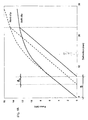
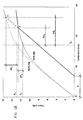
GB1510224A EP0619852B . A known method of manufacturing a resilient rail clip comprises bending a metal rod (usually made of steel) into a predetermined shape and then subjecting the bent rod to a cold setting process to achieve the final form of the clip. - Such rods have a common load-deflection characteristic with a common slope (clip stiffness) up to the elastic limit of the metal from which the bent rod is formed. Cold setting is intended to take the bent rod beyond that elastic limit, thereby inducing a permanent deflection (set) into the resulting clip, such that if it is then unloaded and taken up the load-deflection characteristic a second time, the load-deflection characteristic will be linear up to a much higher load, that is up to the load at which the new characteristic intercepts that for the original rod. One of the key problems in cold-setting is that the metal rods from which the clips are made themselves vary in hardness, typically between 44 and 48 Rockwell hardness. Since the elastic limit of rods made from softer metal is lower than that of rods made from harder metal, if all rods are taken to a fixed deflection, they will all unload down slightly different parallel lines and take on different and varying amounts of set. The softer rods will take on more set, the harder ones less set. This is illustrated in
Figure 1A of the accompanying drawings, which shows the load-deflection characteristics of a soft clip and a hard clip and the difference in set ΔS between them after cold setting. This difference in set results in clips that have different geometries (above and beyond the variation already inherent in manufacture), where the geometry depends on the hardness. Thus, although these cold-set clips will all have the same stiffness, regardless of hardness, driving these clips into a fixed assembly which deflects them all by the same amount will result in the clips generating slightly different loads at the portion (the "toe") of the clip which bears on the railway rail. It is impractical to measure the hardness of each clip to be cold set directly before the start of the cold-setting process. Moreover, as shown inFigures 1B and1C of the accompanying drawings, the problem cannot be overcome simply by changing the fixed amount of deflection applied during cold-setting (Fig. 1B ), or by applying a fixed force instead of a fixed deflection (Fig. 1C ), as this does not address the underlying problem. In the past, in an attempt to address this problem, the rod is repeatedly cold-set a number of times, but this is not fully effective. - According to an embodiment of a first aspect of the present invention there is provided a method of manufacturing a resilient rail clip comprising bending a rod, made of metal having a hardness value falling within a known hardness value range, into a predetermined shape and then subjecting the bent rod to a cold setting process in order to induce in the bent rod a predetermined amount of permanent set, wherein the cold setting process comprises: applying a first load to part of the bent rod so as to cause a first amount of deflection of that part of the bent rod, which first load is a predetermined load having a value equal to or greater than that required to reach the yield point of metal having the highest hardness value in the said hardness value range; measuring the first amount of deflection of the said part of the bent rod achieved by applying the predetermined first load; determining, on the basis of the measured deflection amount, either (i) a second load, which, when applied to the said part of the bent rod, will cause the bent rod to acquire the predetermined amount of permanent set, or (ii) a second amount of deflection of the said part of the bent rod required in order to bring about in the bent rod the predetermined amount of permanent set; and applying the determined second load to the said part of the bent rod or deflecting the said part of the bent rod by the determined second amount of deflection.
- According to an embodiment of a second aspect of the present invention there is provided a method of manufacturing a resilient rail clip comprising bending a rod, made of metal having a hardness value falling within a known hardness value range, into a predetermined shape and then subjecting the bent rod to a cold setting process in order to induce in the bent rod a predetermined amount of permanent set, wherein the cold setting process comprises: deflecting part of the bent rod by a predetermined first amount by applying a first load having a value equal to or greater than that required to reach the yield point of metal having the highest hardness value in the said hardness value range; measuring the amount of the first load required to achieve the predetermined first amount of deflection; determining, on the basis of the measured first load, either (i) a second deflection amount required in order to bring about in the bent rod the predetermined amount of permanent set, or (ii) a second load, which, when applied to the said part of the bent rod, will cause the bent rod to acquire the predetermined amount of permanent set; and deflecting the said part of the bent rod by the determined second deflection amount or applying the determined second load to the said part of the bent rod.
- Reference will now be made, by way of example, to the accompanying drawings, in which:
-
Figures 1A to 1C (described above) show the load-deflection characteristics of two rail clips of different respective hardness which have been cold set according to a previously-proposed method; -
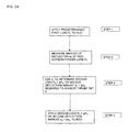
Figures 2A and2B show respective flow diagrams depicting two alternative cold setting processes used in embodiments of the present invention; -
Figure 3A shows a rail clip undergoing part of a cold setting process used in an embodiment of the present invention andFigure 3B shows the same rail clip after cold setting with a set caused by that cold setting process; and -
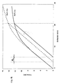
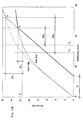
Figures 4A and4B each show the load-deflection characteristics of two rail clips of different respective hardness, the thicker lines showing the characteristics after the clips have been cold set according to a method embodying the present invention and the thinner lines showing the characteristics of the clips before cold setting, in whichFigures 4A and4B correspond respectively to methods embodying the first aspect and the second aspect of the present invention. - According to an embodiment of the present invention a rod of metal, having a hardness value falling within a known hardness value range, is bent into a predetermined clip shape (see
Figure 3A ) and then subjected to a two-stage cold setting process, as shown in the flow diagrams ofFigure 2A or2B . Firstly, the rod is loaded to a level equal to or beyond the yield point of a rod having a hardness value at the top of the hardness value range (STEP 1). Then, depending on the method being used, either a measurement is taken of how much deflection dX has resulted inSTEP 1 from a fixed applied force F0 (STEP 2,Figure 2A ), or how much force FX has been required inSTEP 1 to reach a fixed deflection d0 (STEP 2,Figure 2B ). In the method ofFigure 2A , which embodies the first aspect of the present invention, the measured deflection dX is then used to determine the amount of force F0 + ΔFX or second deflection amount dX + ΔdX (STEP 3,Figure 2A ) required in order to induce in the bent rod a predetermined amount of permanent set S in a second stage of the process, during which the larger force or deflection is applied to the rod. Similarly, in the method ofFigure 2B , which embodies the second aspect of the present invention, the measured force FX is then used to determine the deflection d0 + ΔdX or second load FX + ΔFX (STEP 3,Figure 2B ) required in order to induce in the bent rod a predetermined amount of permanent set S in a second stage of the process, during which the larger deflection or force is applied to the rod. In each case the measured values are used by equipment (and/or by a person) to find the additional force/deflection required, for example by reference to a predetermined look-up table or by calculation. In the second processing stage (STEP 4), the rod is subjected to the force or deflection determined inSTEP 3 of the preceding stage, the amount of which will vary depending on the hardness of the rod, such that the resulting clip (seeFigure 3B ) is always set to a point that lies along a line that is parallel to the initial load-deflection characteristic of the original rod, as shown inFigures 4A and4B . In other words, as shown inFigures 4A and4B , each clip when unloaded will always fall back along an extension of this line, and thus all clips made using this method will have the same amount of set, and therefore the same finished geometry, as each other, regardless of the hardness of the rod. Thus, employing a method embodying the present invention allows the geometry of the clip after the cold-setting process to be closely defined, and in particular it may be more precisely defined than the geometry of the clip before the cold-setting process. -
Figure 4A shows the load-deflection characteristics for clips of different respective hardness, before (thinner lines) and after (thicker lines) cold setting by a method embodying the first aspect of the present invention, in which a measurement is taken of how much deflection, dH (hard clip) or dS (soft clip), has resulted from application to the clip of a fixed applied force F0, and the measured deflection for that clip (dH/dS) is then used to determine the amount of force, F0 + ΔFH (hard clip) or F0 + ΔFS (soft clip), or the amount of deflection, dH + ΔdH (hard clip) or dS + ΔdS (soft clip), required in order to achieve a predetermined amount of permanent set S. All clips cold set in this manner, throughout the whole of the hardness range, will have the same set S. Similarly,Figure 4B shows the load-deflection characteristics for clips of different respective hardness, before (thinner lines) and after (thicker lines) cold setting by a method embodying the second aspect of the present invention, in which a measurement is taken of how much force, FH (hard clip) or FS (soft clip), is required in order to achieve a fixed deflection d0 of the clip, and the measured force for that clip (FH/FS) is then used to determine the amount of deflection, d0 + ΔdH (hard clip) or d0 + ΔdS (soft ciip), or the amount of force, FH + ΔFH (hard clip) or FS + ΔFS (soft clip), required in order to achieve a predetermined amount of permanent set S. All clips cold set in this manner, throughout the whole of the hardness range, will have the same set S. - These methods are particularly advantageous when using hydraulic equipment of the type having force and deflection control, as this allows the determination to be made effectively instantaneously so that there is scarcely a pause in the cold-setting process.
Claims (2)
- A method of manufacturing a resilient rail clip comprising bending a rod, made of metal having a hardness value falling within a known hardness value range, into a predetermined shape and then subjecting the bent rod to a cold setting process in order to induce in the bent rod a predetermined amount of permanent set, characterized in that the cold setting process comprises:applying a first load to part of the bent rod so as to cause a first amount of deflection of that part of the bent rod, which first load is a predetermined load having a value equal to or greater than that required to reach the yield point of metal having the highest hardness value in the said hardness value range;measuring the first amount of deflection of the said part of the bent rod achieved by applying the predetermined first load;determining, on the basis of the measured deflection amount, either (i) a second load, which, when applied to the said part of the bent rod, will cause the bent rod to acquire the predetermined amount of permanent set, or (ii) a second amount of deflection of the said part of the bent rod required in order to bring about in the bent rod the predetermined amount of permanent set; andapplying the determined second load to the said part of the bent rod or deflecting the said part of the bent rod by the determined second amount of deflection.
- A method of manufacturing a resilient rail clip comprising bending a rod, made of metal having a hardness value falling within a known hardness value range, into a predetermined shape and then subjecting the bent rod to a cold setting process in order to induce in the bent rod a predetermined amount of permanent set characterized in that the cold setting process comprises:deflecting part of the bent rod by a predetermined first amount by applying a first load having a value equal to or greater than that required to reach the yield point of metal having the highest hardness value in the said hardness value range;measuring the amount of the first load required to achieve the predetermined first amount of deflection;determining, on the basis of the measured first load, either (i) a second deflection amount required in order to bring about in the bent rod the predetermined amount of permanent set, or (ii) a second load, which, when applied to the said part of the bent rod, will cause the bent rod to acquire the predetermined amount of permanent set; anddeflecting the said part of the bent rod by the determined second deflection amount or applying the determined second load to the said part of the bent rod.
Priority Applications (2)
| Application Number | Priority Date | Filing Date | Title |
|---|---|---|---|
| PL10796315T PL2528702T3 (en) | 2010-01-27 | 2010-12-03 | Methods of manufacturing a resilient rail clip |
| SI201030911T SI2528702T1 (en) | 2010-01-27 | 2010-12-03 | Methods of manufacturing a resilient rail clip |
Applications Claiming Priority (2)
| Application Number | Priority Date | Filing Date | Title |
|---|---|---|---|
| GB1001301A GB2477282A (en) | 2010-01-27 | 2010-01-27 | Method of manufacturing a resilient metal rail clip with hardness within a known range |
| PCT/EP2010/068893 WO2011091893A1 (en) | 2010-01-27 | 2010-12-03 | Methods of manufacturing a resilient rail clip |
Publications (2)
| Publication Number | Publication Date |
|---|---|
| EP2528702A1 EP2528702A1 (en) | 2012-12-05 |
| EP2528702B1 true EP2528702B1 (en) | 2015-02-18 |
Family
ID=42046114
Family Applications (1)
| Application Number | Title | Priority Date | Filing Date |
|---|---|---|---|
| EP10796315.9A Active EP2528702B1 (en) | 2010-01-27 | 2010-12-03 | Methods of manufacturing a resilient rail clip |
Country Status (18)
| Country | Link |
|---|---|
| US (1) | US20130074559A1 (en) |
| EP (1) | EP2528702B1 (en) |
| JP (1) | JP5677466B2 (en) |
| KR (1) | KR101779394B1 (en) |
| CN (1) | CN102712028B (en) |
| AU (1) | AU2010344043B2 (en) |
| BR (1) | BR112012017549B1 (en) |
| CA (1) | CA2787694C (en) |
| DK (1) | DK2528702T3 (en) |
| ES (1) | ES2531309T3 (en) |
| GB (1) | GB2477282A (en) |
| MX (1) | MX2012008685A (en) |
| PL (1) | PL2528702T3 (en) |
| PT (1) | PT2528702E (en) |
| RU (1) | RU2543588C2 (en) |
| SI (1) | SI2528702T1 (en) |
| WO (1) | WO2011091893A1 (en) |
| ZA (1) | ZA201205545B (en) |
Families Citing this family (1)
| Publication number | Priority date | Publication date | Assignee | Title |
|---|---|---|---|---|
| EP4332300A1 (en) | 2022-08-29 | 2024-03-06 | voestalpine Turnout Technology Zeltweg GmbH | Tension spring for holding down a track body element |
Family Cites Families (18)
| Publication number | Priority date | Publication date | Assignee | Title |
|---|---|---|---|---|
| NL163277C (en) * | 1974-02-26 | 1984-03-16 | Everts & Van Der Weyden Nv | METHOD FOR MAKING A RAIL CLAMP. |
| GB1510224A (en) | 1975-11-07 | 1978-05-10 | Pandrol Ltd | Railway rail fastening clip and a railway rail-and-fastening assembly employing it |
| NL182379C (en) * | 1978-07-19 | 1988-03-01 | Everts & Van Der Weyden Nv | METHOD OF MANUFACTURING A C-SHAPED RAIL CLAMP. |
| US4300380A (en) * | 1978-10-13 | 1981-11-17 | Pandrol Limited | Apparatus and a method for use in making a railway rail-fastening clip |
| ZA796441B (en) | 1978-11-29 | 1980-11-26 | Pandrol Ltd | A rail clip and apparatus for making it |
| NL7906455A (en) * | 1979-08-28 | 1981-03-03 | Everts & Van Der Weyden Nv | RAIL CLAMP. |
| DE2965999D1 (en) * | 1979-10-26 | 1983-09-01 | Mckay Ralph Ltd | A rail clip holder |
| OA09065A (en) * | 1987-10-19 | 1991-10-31 | Pandrol Ltd | Fastening railway rails. |
| IN185922B (en) * | 1991-12-18 | 2001-05-19 | Pandrol Ltd | |
| JPH08510304A (en) * | 1993-06-02 | 1996-10-29 | イグウェメジー,ジュード,オディハッチャックウンマ | Improved rail sleepers, tie plates and fasteners |
| GB2298442B (en) * | 1995-03-03 | 1999-01-13 | Pandrol Ltd | Railway rail-fastening clip and assembly |
| US7383709B2 (en) * | 2005-08-04 | 2008-06-10 | Custom Machining Services, Inc. | System and process for crimping a fitting to a fluid conduit |
| JP4842758B2 (en) * | 2006-10-06 | 2011-12-21 | 太平工業株式会社 | Rail fastening method with wire spring clip |
| TW200914163A (en) * | 2007-05-09 | 2009-04-01 | Nippon Steel Corp | Thin plate press molding device and thin plate press molding method |
| HUP0800082A2 (en) * | 2008-02-12 | 2009-10-28 | Robert Csepke | Clamping device for fastening railway rails on cross-sleeper and fastener spring thereof |
| ITRM20080078A1 (en) * | 2008-02-12 | 2009-08-13 | Cml Intarnational S P A | METHOD OF VERIFICATION AND COMMAND TO CURVE IN AN CONTINUOUS WAY A PIECE EXTENDED ACCORDING TO VARIABLE CURCATORS SPOKES AND MACHINE SO COMMANDED |
| AU2010201544A1 (en) * | 2009-04-21 | 2010-11-04 | Betaswage Pty Ltd | Control of metal cold forming machines |
| IT1394105B1 (en) * | 2009-05-06 | 2012-05-25 | Cml Int Spa | MACHINE TO TURN CONTINUOUSLY AN EXTENDED PIECE ACCORDING TO PREDETERMINATED RAYS |
-
2010
- 2010-01-27 GB GB1001301A patent/GB2477282A/en not_active Withdrawn
- 2010-12-03 RU RU2012136430/02A patent/RU2543588C2/en active
- 2010-12-03 PL PL10796315T patent/PL2528702T3/en unknown
- 2010-12-03 US US13/520,522 patent/US20130074559A1/en not_active Abandoned
- 2010-12-03 BR BR112012017549A patent/BR112012017549B1/en active IP Right Grant
- 2010-12-03 KR KR1020127022098A patent/KR101779394B1/en active IP Right Grant
- 2010-12-03 MX MX2012008685A patent/MX2012008685A/en active IP Right Grant
- 2010-12-03 DK DK10796315.9T patent/DK2528702T3/en active
- 2010-12-03 SI SI201030911T patent/SI2528702T1/en unknown
- 2010-12-03 EP EP10796315.9A patent/EP2528702B1/en active Active
- 2010-12-03 PT PT107963159T patent/PT2528702E/en unknown
- 2010-12-03 CA CA2787694A patent/CA2787694C/en active Active
- 2010-12-03 WO PCT/EP2010/068893 patent/WO2011091893A1/en active Application Filing
- 2010-12-03 ES ES10796315T patent/ES2531309T3/en active Active
- 2010-12-03 AU AU2010344043A patent/AU2010344043B2/en active Active
- 2010-12-03 JP JP2012550340A patent/JP5677466B2/en active Active
- 2010-12-03 CN CN201080062326.7A patent/CN102712028B/en active Active
-
2012
- 2012-07-23 ZA ZA2012/05545A patent/ZA201205545B/en unknown
Also Published As
| Publication number | Publication date |
|---|---|
| DK2528702T3 (en) | 2015-05-26 |
| CN102712028B (en) | 2014-11-05 |
| JP2013518196A (en) | 2013-05-20 |
| EP2528702A1 (en) | 2012-12-05 |
| CN102712028A (en) | 2012-10-03 |
| RU2012136430A (en) | 2014-03-10 |
| WO2011091893A1 (en) | 2011-08-04 |
| AU2010344043B2 (en) | 2014-07-17 |
| CA2787694C (en) | 2017-02-07 |
| RU2543588C2 (en) | 2015-03-10 |
| US20130074559A1 (en) | 2013-03-28 |
| AU2010344043A1 (en) | 2012-08-16 |
| PL2528702T3 (en) | 2015-07-31 |
| ZA201205545B (en) | 2013-04-24 |
| JP5677466B2 (en) | 2015-02-25 |
| PT2528702E (en) | 2015-02-27 |
| BR112012017549B1 (en) | 2020-04-22 |
| MX2012008685A (en) | 2012-08-23 |
| GB201001301D0 (en) | 2010-03-10 |
| ES2531309T3 (en) | 2015-03-12 |
| GB2477282A (en) | 2011-08-03 |
| CA2787694A1 (en) | 2011-08-04 |
| KR101779394B1 (en) | 2017-09-18 |
| KR20120116006A (en) | 2012-10-19 |
| SI2528702T1 (en) | 2015-05-29 |
| BR112012017549A2 (en) | 2016-06-28 |
Similar Documents
| Publication | Publication Date | Title |
|---|---|---|
| CN109635385B (en) | Part service life prediction method comprehensively considering fatigue strength influence factors | |
| CN109165407A (en) | A kind of predictor method for the mechanical component fatigue crack service life | |
| Baik et al. | Fatigue crack propagation analysis for welded joint subjected to bending | |
| Katsanos et al. | Inelastic spectra to predict period elongation of structures under earthquake loading | |
| JP4694327B2 (en) | Creep rupture life estimation method, material selection method, design method and manufacturing method of metal insert resin molded product | |
| CN105260574A (en) | Critical plane method fatigue failure criterion-based high-cycle multi-axial fatigue life prediction method | |
| Strzelecki et al. | Application of Weibull distribution to describe SN curve with using small number specimens | |
| EP2528702B1 (en) | Methods of manufacturing a resilient rail clip | |
| El-Sayed et al. | A three dimensional finite element analysis of insulated rail joints deterioration | |
| KR102458926B1 (en) | Method for predicting polymer properties | |
| KR102168832B1 (en) | Method of evaluating formability of bulk metallic mateterial | |
| KR101899690B1 (en) | Method and Apparatus for Optimizing Production Conditions of Plate Using Standardization of DWTT Shear Area Data | |
| JP4733158B2 (en) | Elastic modulus measurement method | |
| Real et al. | Fatigue behaviour of duplex stainless steel reinforcing bars subjected to shot peening | |
| Langenhorst et al. | Analysis of internal material loads and resulting modifications for grinding with mechanical main impact | |
| US6474135B1 (en) | Laser peening to provide design credit for improved fatigue properties | |
| Lillamand et al. | Cyclic modelling of the mechanical state produced by shot‐peening | |
| JP5363792B2 (en) | Design method of raw material in hot ring rolling process | |
| JPH1164203A (en) | Method for estimating fatigue life of copper material | |
| JP6562395B2 (en) | Method for estimating phase transformation behavior of polycrystalline shape memory alloys | |
| RU2263156C1 (en) | Method of selection of modes of heat treatment of elastic members made from beryllium bronze | |
| Levieil et al. | Predicting residual stresses influence on crack initiation for low-cycle fatigue | |
| Volkov et al. | Deformation diagrams of metals with different types of microstructure damage | |
| PL440700A1 (en) | Panel of predictive markers, method for predicting the occurrence of drug-resistant epilepsy in girls aged up to 24 months with tuberous sclerosis and use of a panel of markers in this method | |
| Yamashita et al. | Numerical simulation of fatigue crack propagation and crack opening and closing model by considering the strain-hardening effect of materials |
Legal Events
| Date | Code | Title | Description |
|---|---|---|---|
| PUAI | Public reference made under article 153(3) epc to a published international application that has entered the european phase |
Free format text: ORIGINAL CODE: 0009012 |
|
| 17P | Request for examination filed |
Effective date: 20120820 |
|
| AK | Designated contracting states |
Kind code of ref document: A1 Designated state(s): AL AT BE BG CH CY CZ DE DK EE ES FI FR GB GR HR HU IE IS IT LI LT LU LV MC MK MT NL NO PL PT RO RS SE SI SK SM TR |
|
| DAX | Request for extension of the european patent (deleted) | ||
| GRAP | Despatch of communication of intention to grant a patent |
Free format text: ORIGINAL CODE: EPIDOSNIGR1 |
|
| INTG | Intention to grant announced |
Effective date: 20140729 |
|
| GRAS | Grant fee paid |
Free format text: ORIGINAL CODE: EPIDOSNIGR3 |
|
| GRAA | (expected) grant |
Free format text: ORIGINAL CODE: 0009210 |
|
| AK | Designated contracting states |
Kind code of ref document: B1 Designated state(s): AL AT BE BG CH CY CZ DE DK EE ES FI FR GB GR HR HU IE IS IT LI LT LU LV MC MK MT NL NO PL PT RO RS SE SI SK SM TR |
|
| REG | Reference to a national code |
Ref country code: GB Ref legal event code: FG4D |
|
| REG | Reference to a national code |
Ref country code: CH Ref legal event code: NV Representative=s name: DR. LUSUARDI AG, CH Ref country code: CH Ref legal event code: EP Ref country code: PT Ref legal event code: SC4A Free format text: AVAILABILITY OF NATIONAL TRANSLATION Effective date: 20150220 |
|
| REG | Reference to a national code |
Ref country code: RO Ref legal event code: EPE |
|
| REG | Reference to a national code |
Ref country code: ES Ref legal event code: FG2A Ref document number: 2531309 Country of ref document: ES Kind code of ref document: T3 Effective date: 20150312 |
|
| REG | Reference to a national code |
Ref country code: AT Ref legal event code: REF Ref document number: 710438 Country of ref document: AT Kind code of ref document: T Effective date: 20150315 |
|
| REG | Reference to a national code |
Ref country code: IE Ref legal event code: FG4D |
|
| REG | Reference to a national code |
Ref country code: DE Ref legal event code: R096 Ref document number: 602010022360 Country of ref document: DE Effective date: 20150402 |
|
| REG | Reference to a national code |
Ref country code: NL Ref legal event code: T3 |
|
| REG | Reference to a national code |
Ref country code: GR Ref legal event code: EP Ref document number: 20150400378 Country of ref document: GR Effective date: 20150318 |
|
| REG | Reference to a national code |
Ref country code: SE Ref legal event code: TRGR Ref country code: DK Ref legal event code: T3 Effective date: 20150521 |
|
| REG | Reference to a national code |
Ref country code: EE Ref legal event code: FG4A Ref document number: E010471 Country of ref document: EE Effective date: 20150420 |
|
| REG | Reference to a national code |
Ref country code: NO Ref legal event code: T2 Effective date: 20150218 |
|
| PG25 | Lapsed in a contracting state [announced via postgrant information from national office to epo] |
Ref country code: HR Free format text: LAPSE BECAUSE OF FAILURE TO SUBMIT A TRANSLATION OF THE DESCRIPTION OR TO PAY THE FEE WITHIN THE PRESCRIBED TIME-LIMIT Effective date: 20150218 |
|
| REG | Reference to a national code |
Ref country code: PL Ref legal event code: T3 |
|
| REG | Reference to a national code |
Ref country code: SK Ref legal event code: T3 Ref document number: E 18604 Country of ref document: SK |
|
| PG25 | Lapsed in a contracting state [announced via postgrant information from national office to epo] |
Ref country code: RS Free format text: LAPSE BECAUSE OF FAILURE TO SUBMIT A TRANSLATION OF THE DESCRIPTION OR TO PAY THE FEE WITHIN THE PRESCRIBED TIME-LIMIT Effective date: 20150218 Ref country code: IS Free format text: LAPSE BECAUSE OF FAILURE TO SUBMIT A TRANSLATION OF THE DESCRIPTION OR TO PAY THE FEE WITHIN THE PRESCRIBED TIME-LIMIT Effective date: 20150618 |
|
| REG | Reference to a national code |
Ref country code: DE Ref legal event code: R097 Ref document number: 602010022360 Country of ref document: DE |
|
| REG | Reference to a national code |
Ref country code: HU Ref legal event code: AG4A Ref document number: E024319 Country of ref document: HU |
|
| REG | Reference to a national code |
Ref country code: FR Ref legal event code: PLFP Year of fee payment: 6 |
|
| PLBE | No opposition filed within time limit |
Free format text: ORIGINAL CODE: 0009261 |
|
| STAA | Information on the status of an ep patent application or granted ep patent |
Free format text: STATUS: NO OPPOSITION FILED WITHIN TIME LIMIT |
|
| 26N | No opposition filed |
Effective date: 20151119 |
|
| REG | Reference to a national code |
Ref country code: AT Ref legal event code: UEP Ref document number: 710438 Country of ref document: AT Kind code of ref document: T Effective date: 20150218 |
|
| PG25 | Lapsed in a contracting state [announced via postgrant information from national office to epo] |
Ref country code: LU Free format text: LAPSE BECAUSE OF FAILURE TO SUBMIT A TRANSLATION OF THE DESCRIPTION OR TO PAY THE FEE WITHIN THE PRESCRIBED TIME-LIMIT Effective date: 20151203 Ref country code: MC Free format text: LAPSE BECAUSE OF FAILURE TO SUBMIT A TRANSLATION OF THE DESCRIPTION OR TO PAY THE FEE WITHIN THE PRESCRIBED TIME-LIMIT Effective date: 20150218 |
|
| REG | Reference to a national code |
Ref country code: IE Ref legal event code: MM4A |
|
| PG25 | Lapsed in a contracting state [announced via postgrant information from national office to epo] |
Ref country code: IE Free format text: LAPSE BECAUSE OF NON-PAYMENT OF DUE FEES Effective date: 20151203 |
|
| REG | Reference to a national code |
Ref country code: FR Ref legal event code: PLFP Year of fee payment: 7 |
|
| PG25 | Lapsed in a contracting state [announced via postgrant information from national office to epo] |
Ref country code: SM Free format text: LAPSE BECAUSE OF FAILURE TO SUBMIT A TRANSLATION OF THE DESCRIPTION OR TO PAY THE FEE WITHIN THE PRESCRIBED TIME-LIMIT Effective date: 20150218 |
|
| PG25 | Lapsed in a contracting state [announced via postgrant information from national office to epo] |
Ref country code: CY Free format text: LAPSE BECAUSE OF FAILURE TO SUBMIT A TRANSLATION OF THE DESCRIPTION OR TO PAY THE FEE WITHIN THE PRESCRIBED TIME-LIMIT Effective date: 20150218 |
|
| PG25 | Lapsed in a contracting state [announced via postgrant information from national office to epo] |
Ref country code: MT Free format text: LAPSE BECAUSE OF FAILURE TO SUBMIT A TRANSLATION OF THE DESCRIPTION OR TO PAY THE FEE WITHIN THE PRESCRIBED TIME-LIMIT Effective date: 20150218 |
|
| REG | Reference to a national code |
Ref country code: FR Ref legal event code: PLFP Year of fee payment: 8 |
|
| PG25 | Lapsed in a contracting state [announced via postgrant information from national office to epo] |
Ref country code: MK Free format text: LAPSE BECAUSE OF FAILURE TO SUBMIT A TRANSLATION OF THE DESCRIPTION OR TO PAY THE FEE WITHIN THE PRESCRIBED TIME-LIMIT Effective date: 20150218 |
|
| PG25 | Lapsed in a contracting state [announced via postgrant information from national office to epo] |
Ref country code: AL Free format text: LAPSE BECAUSE OF FAILURE TO SUBMIT A TRANSLATION OF THE DESCRIPTION OR TO PAY THE FEE WITHIN THE PRESCRIBED TIME-LIMIT Effective date: 20150218 |
|
| REG | Reference to a national code |
Ref country code: DE Ref legal event code: R082 Ref document number: 602010022360 Country of ref document: DE Representative=s name: HL KEMPNER PATENTANWAELTE, SOLICITORS (ENGLAND, DE Ref country code: DE Ref legal event code: R082 Ref document number: 602010022360 Country of ref document: DE Representative=s name: HL KEMPNER PATENTANWALT, RECHTSANWALT, SOLICIT, DE |
|
| PGFP | Annual fee paid to national office [announced via postgrant information from national office to epo] |
Ref country code: AT Payment date: 20201209 Year of fee payment: 11 |
|
| PGFP | Annual fee paid to national office [announced via postgrant information from national office to epo] |
Ref country code: ES Payment date: 20210114 Year of fee payment: 11 |
|
| REG | Reference to a national code |
Ref country code: AT Ref legal event code: MM01 Ref document number: 710438 Country of ref document: AT Kind code of ref document: T Effective date: 20211203 |
|
| PG25 | Lapsed in a contracting state [announced via postgrant information from national office to epo] |
Ref country code: AT Free format text: LAPSE BECAUSE OF NON-PAYMENT OF DUE FEES Effective date: 20211203 |
|
| REG | Reference to a national code |
Ref country code: ES Ref legal event code: FD2A Effective date: 20230222 |
|
| PG25 | Lapsed in a contracting state [announced via postgrant information from national office to epo] |
Ref country code: ES Free format text: LAPSE BECAUSE OF NON-PAYMENT OF DUE FEES Effective date: 20211204 |
|
| PGFP | Annual fee paid to national office [announced via postgrant information from national office to epo] |
Ref country code: CH Payment date: 20221219 Year of fee payment: 13 |
|
| P01 | Opt-out of the competence of the unified patent court (upc) registered |
Effective date: 20230330 |
|
| PGFP | Annual fee paid to national office [announced via postgrant information from national office to epo] |
Ref country code: SK Payment date: 20231114 Year of fee payment: 14 |
|
| PGFP | Annual fee paid to national office [announced via postgrant information from national office to epo] |
Ref country code: GB Payment date: 20231219 Year of fee payment: 14 |
|
| PGFP | Annual fee paid to national office [announced via postgrant information from national office to epo] |
Ref country code: TR Payment date: 20231120 Year of fee payment: 14 Ref country code: SI Payment date: 20231117 Year of fee payment: 14 Ref country code: SE Payment date: 20231219 Year of fee payment: 14 Ref country code: RO Payment date: 20231114 Year of fee payment: 14 Ref country code: PT Payment date: 20231110 Year of fee payment: 14 Ref country code: NO Payment date: 20231206 Year of fee payment: 14 Ref country code: NL Payment date: 20231219 Year of fee payment: 14 Ref country code: LV Payment date: 20231227 Year of fee payment: 14 Ref country code: LT Payment date: 20231110 Year of fee payment: 14 Ref country code: IT Payment date: 20231211 Year of fee payment: 14 Ref country code: HU Payment date: 20231115 Year of fee payment: 14 Ref country code: FR Payment date: 20231211 Year of fee payment: 14 Ref country code: FI Payment date: 20231207 Year of fee payment: 14 Ref country code: EE Payment date: 20231219 Year of fee payment: 14 Ref country code: DK Payment date: 20231219 Year of fee payment: 14 Ref country code: DE Payment date: 20231219 Year of fee payment: 14 Ref country code: CZ Payment date: 20231110 Year of fee payment: 14 Ref country code: BG Payment date: 20231220 Year of fee payment: 14 |
|
| PGFP | Annual fee paid to national office [announced via postgrant information from national office to epo] |
Ref country code: PL Payment date: 20231121 Year of fee payment: 14 Ref country code: BE Payment date: 20231214 Year of fee payment: 14 |
|
| PGFP | Annual fee paid to national office [announced via postgrant information from national office to epo] |
Ref country code: GR Payment date: 20240103 Year of fee payment: 14 |
|
| PGFP | Annual fee paid to national office [announced via postgrant information from national office to epo] |
Ref country code: CH Payment date: 20240101 Year of fee payment: 14 |