EP2528150A1 - Fuel cell system - Google Patents
Fuel cell system Download PDFInfo
- Publication number
- EP2528150A1 EP2528150A1 EP10843975A EP10843975A EP2528150A1 EP 2528150 A1 EP2528150 A1 EP 2528150A1 EP 10843975 A EP10843975 A EP 10843975A EP 10843975 A EP10843975 A EP 10843975A EP 2528150 A1 EP2528150 A1 EP 2528150A1
- Authority
- EP
- European Patent Office
- Prior art keywords
- fuel cell
- electrode
- cell system
- fuel
- hydrogen
- Prior art date
- Legal status (The legal status is an assumption and is not a legal conclusion. Google has not performed a legal analysis and makes no representation as to the accuracy of the status listed.)
- Withdrawn
Links
Images


Classifications
-
- H—ELECTRICITY
- H01—ELECTRIC ELEMENTS
- H01M—PROCESSES OR MEANS, e.g. BATTERIES, FOR THE DIRECT CONVERSION OF CHEMICAL ENERGY INTO ELECTRICAL ENERGY
- H01M8/00—Fuel cells; Manufacture thereof
- H01M8/06—Combination of fuel cells with means for production of reactants or for treatment of residues
- H01M8/0606—Combination of fuel cells with means for production of reactants or for treatment of residues with means for production of gaseous reactants
- H01M8/065—Combination of fuel cells with means for production of reactants or for treatment of residues with means for production of gaseous reactants by dissolution of metals or alloys; by dehydriding metallic substances
-
- H—ELECTRICITY
- H01—ELECTRIC ELEMENTS
- H01M—PROCESSES OR MEANS, e.g. BATTERIES, FOR THE DIRECT CONVERSION OF CHEMICAL ENERGY INTO ELECTRICAL ENERGY
- H01M8/00—Fuel cells; Manufacture thereof
- H01M8/04—Auxiliary arrangements, e.g. for control of pressure or for circulation of fluids
- H01M8/04007—Auxiliary arrangements, e.g. for control of pressure or for circulation of fluids related to heat exchange
- H01M8/04037—Electrical heating
-
- H—ELECTRICITY
- H01—ELECTRIC ELEMENTS
- H01M—PROCESSES OR MEANS, e.g. BATTERIES, FOR THE DIRECT CONVERSION OF CHEMICAL ENERGY INTO ELECTRICAL ENERGY
- H01M8/00—Fuel cells; Manufacture thereof
- H01M8/04—Auxiliary arrangements, e.g. for control of pressure or for circulation of fluids
- H01M8/04082—Arrangements for control of reactant parameters, e.g. pressure or concentration
- H01M8/04201—Reactant storage and supply, e.g. means for feeding, pipes
- H01M8/04208—Cartridges, cryogenic media or cryogenic reservoirs
-
- H—ELECTRICITY
- H01—ELECTRIC ELEMENTS
- H01M—PROCESSES OR MEANS, e.g. BATTERIES, FOR THE DIRECT CONVERSION OF CHEMICAL ENERGY INTO ELECTRICAL ENERGY
- H01M8/00—Fuel cells; Manufacture thereof
- H01M8/18—Regenerative fuel cells, e.g. redox flow batteries or secondary fuel cells
- H01M8/184—Regeneration by electrochemical means
- H01M8/186—Regeneration by electrochemical means by electrolytic decomposition of the electrolytic solution or the formed water product
-
- H—ELECTRICITY
- H01—ELECTRIC ELEMENTS
- H01M—PROCESSES OR MEANS, e.g. BATTERIES, FOR THE DIRECT CONVERSION OF CHEMICAL ENERGY INTO ELECTRICAL ENERGY
- H01M8/00—Fuel cells; Manufacture thereof
- H01M8/10—Fuel cells with solid electrolytes
- H01M8/12—Fuel cells with solid electrolytes operating at high temperature, e.g. with stabilised ZrO2 electrolyte
- H01M2008/1293—Fuel cells with solid oxide electrolytes
-
- H—ELECTRICITY
- H01—ELECTRIC ELEMENTS
- H01M—PROCESSES OR MEANS, e.g. BATTERIES, FOR THE DIRECT CONVERSION OF CHEMICAL ENERGY INTO ELECTRICAL ENERGY
- H01M2250/00—Fuel cells for particular applications; Specific features of fuel cell system
- H01M2250/30—Fuel cells in portable systems, e.g. mobile phone, laptop
-
- H—ELECTRICITY
- H01—ELECTRIC ELEMENTS
- H01M—PROCESSES OR MEANS, e.g. BATTERIES, FOR THE DIRECT CONVERSION OF CHEMICAL ENERGY INTO ELECTRICAL ENERGY
- H01M8/00—Fuel cells; Manufacture thereof
- H01M8/04—Auxiliary arrangements, e.g. for control of pressure or for circulation of fluids
- H01M8/04007—Auxiliary arrangements, e.g. for control of pressure or for circulation of fluids related to heat exchange
-
- H—ELECTRICITY
- H01—ELECTRIC ELEMENTS
- H01M—PROCESSES OR MEANS, e.g. BATTERIES, FOR THE DIRECT CONVERSION OF CHEMICAL ENERGY INTO ELECTRICAL ENERGY
- H01M8/00—Fuel cells; Manufacture thereof
- H01M8/04—Auxiliary arrangements, e.g. for control of pressure or for circulation of fluids
- H01M8/04082—Arrangements for control of reactant parameters, e.g. pressure or concentration
- H01M8/04201—Reactant storage and supply, e.g. means for feeding, pipes
- H01M8/04216—Reactant storage and supply, e.g. means for feeding, pipes characterised by the choice for a specific material, e.g. carbon, hydride, absorbent
-
- Y—GENERAL TAGGING OF NEW TECHNOLOGICAL DEVELOPMENTS; GENERAL TAGGING OF CROSS-SECTIONAL TECHNOLOGIES SPANNING OVER SEVERAL SECTIONS OF THE IPC; TECHNICAL SUBJECTS COVERED BY FORMER USPC CROSS-REFERENCE ART COLLECTIONS [XRACs] AND DIGESTS
- Y02—TECHNOLOGIES OR APPLICATIONS FOR MITIGATION OR ADAPTATION AGAINST CLIMATE CHANGE
- Y02B—CLIMATE CHANGE MITIGATION TECHNOLOGIES RELATED TO BUILDINGS, e.g. HOUSING, HOUSE APPLIANCES OR RELATED END-USER APPLICATIONS
- Y02B90/00—Enabling technologies or technologies with a potential or indirect contribution to GHG emissions mitigation
- Y02B90/10—Applications of fuel cells in buildings
-
- Y—GENERAL TAGGING OF NEW TECHNOLOGICAL DEVELOPMENTS; GENERAL TAGGING OF CROSS-SECTIONAL TECHNOLOGIES SPANNING OVER SEVERAL SECTIONS OF THE IPC; TECHNICAL SUBJECTS COVERED BY FORMER USPC CROSS-REFERENCE ART COLLECTIONS [XRACs] AND DIGESTS
- Y02—TECHNOLOGIES OR APPLICATIONS FOR MITIGATION OR ADAPTATION AGAINST CLIMATE CHANGE
- Y02E—REDUCTION OF GREENHOUSE GAS [GHG] EMISSIONS, RELATED TO ENERGY GENERATION, TRANSMISSION OR DISTRIBUTION
- Y02E60/00—Enabling technologies; Technologies with a potential or indirect contribution to GHG emissions mitigation
- Y02E60/30—Hydrogen technology
- Y02E60/50—Fuel cells
Definitions
- the present invention relates to a fuel cell system, more particularly, to a fuel cell system that includes a hydrogen occlusion material.
- a patent document 1 describes a chargeable fuel cell system; in this fuel system, a fuel cell and a hydrogen occlusion material are integrally formed with each other; and as the fuel cell, a solid polymer electrolyte fuel cell (hereinafter, called a PEFC) is used.
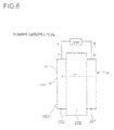
- Fig. 6 is a schematic view showing a reaction mechanism of a PEFC during a power generation time
- Fig. 7 is a schematic view showing a reaction mechanism of a PEFC during a charge time.
- a PEFC 200 is composed of a fuel electrode 221, an oxygen electrode 222, and an electrolyte membrane 223; and during a power generation time, at the fuel electrode 221, protons and electrons are generated from hydrogen; at the oxygen electrode 222, protons moving from the fuel electrode 221 and oxygen ions generated from oxygen react to each other to generate water.
- the fuel electrode H 2 ⁇ 2H + + 2e -
- the oxygen electrode 4H + + O 2 + 4e - ⁇ 2H 2 O
- the hydrogen occlusion material for generating hydrogen is disposed; accordingly, during the power generation time, it is possible to supply hydrogen from the hydrogen occlusion material to the fuel electrode; and during the charge time, it is possible to make the hydrogen occlusion material occlude and store the hydrogen generated by the fuel electrode.
- a fuel cell system includes: a fuel cell that includes: a fuel electrode, an oxygen electrode, and an electrolyte membrane disposed between the fuel electrode and the oxygen electrode; a hydrogen occlusion material that supplies hydrogen to the fuel electrode; and an reaction container that incorporates the hydrogen occlusion material and has a temperature adjustment mechanism which adjusts an internal condition; wherein the fuel electrode generates water by means of the fuel electrode during a power generation time, and supplies the water to an inside of the reaction container.
- this structure it is possible to adjust the internal condition of the reaction container by means of the temperature adjustment mechanism, and control a reaction start condition of the hydrogen occlusion material and a reaction stop condition of the hydrogen occlusion material. In this way, during a power generation time, it is possible to make the hydrogen occlusion material emit hydrogen stably; and during a charge time, it is possible to stably store the hydrogen in the hydrogen occlusion material.
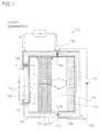
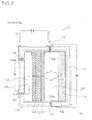
- Fig. 1 and Fig. 2 are schematic views of a fuel cell system according to a first embodiment, of which Fig. 1 shows a state during a power generation time, and Fig. 2 shows a state during a charge time.
- a fuel cell system 101 is composed of a solid oxide fuel cell 120 (hereinafter, called an SOFC) and a reaction container 103.
- the SOFC 120 is composed of a fuel electrode 121, an electrolyte membrane 123, and an oxygen electrode 122.
- an air chamber 124 is formed on an oxygen electrode 122 side of the SOFC 120
- a fuel chamber 128 is formed on a fuel electrode 121 side.
- the fuel chamber 128 is formed of an air space between the fuel electrode 121 and an inside of the reaction container 103 that is disposed adjacently to the fuel electrode 121.
- the reaction container 103 is mounted so as not to be electrically connected to the SOFC 120 via a first connection portion 112 and a second connection portion 113.
- the reaction container 103 includes a heat-insulated structure having a cavity 170 between an outer wall and an inner wall, and has a first heater 114 for heating the inside of the reaction container 103.
- a fuel diffusion layer is formed on a surface of the fuel electrode 121, whereby it is possible to evenly supply hydrogen to the fuel electrode 121
- an air diffusion layer is formed on a surface of the oxygen electrode 122, whereby it is possible to evenly supply air to the oxygen electrode 121.
- the air chamber 124 communicates with an oxygen supply line 125 and an oxygen discharge line 127, whereby air containing oxygen is supplied into an inside of the air chamber 124 via the oxygen supply line 125.
- the oxygen supply line 125 is provided with a valve 125a and the oxygen discharge line 127 is provided with a valve 127a, whereby it is possible to control the air supply into the air chamber 124.
- the hydrogen occlusion material 106 is formed of the iron microparticles, which allow the following oxidation and reduction reactions to occur in the reaction container 103.
- the hydrogen occlusion material 106 emits hydrogen by means of an iron oxidation reaction during a power generation time, and stores hydrogen by means of an iron oxide reduction reaction during a charge time.
- the reduction reaction at the hydrogen occlusion material 106 is an endothermic reaction and the reaction temperature is high; however, by adjusting the internal temperature of the reaction container 103 by means of the first heater 114, it is possible to control the reaction at the hydrogen occlusion material 106.
- Fig. 3 is a schematic view showing a reaction mechanism of the SOFC during a power generation time
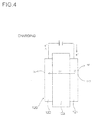
- Fig. 4 is a schematic view showing a reaction mechanism of the SOFC during a charge time.
- the following reactions occur at the fuel electrode 121 and the oxygen electrode 122, whereby at the fuel electrode 121, protons and electrons are generated from hydrogen and at the oxygen electrode 122, oxygen ions are generated from oxygen.
- oxygen ions moving from the oxygen electrode 122 and protons react to each other, whereby water is generated at the fuel electrode 121.
- the first connection portion 112 and the second connection portion 113 are closed to tightly seal the reaction container 103, and the inside of the fuel chamber 128 is heated by means of the first heater 114, whereby the iron as the hydrogen occlusion material 106 is oxidized in the reaction container 103 to generate hydrogen, which is supplied to the fuel electrode 121.
- the first connection portion 112 and the second connection portion 113 may be normally closed in a state where the reaction container 103 is mounted on the SOFC 120.
- the valve 125a of the oxygen supply line 125 and the valve 127a of the oxygen discharge line 127 are opened, whereby oxygen is supplied to the oxygen electrode 122 and the inside of the air chamber 124 is heated by means of a second heater 126.
- the SOFC 120 generates electric power by means of the electrochemical reaction.
- the water generated at the fuel electrode 121 is supplied to the hydrogen occlusion material 106 in the inside of the reaction container 103, thereby prompting the hydrogen generation reaction at the hydrogen occlusion material 106.
- the water used for the hydrogen generation reaction at the hydrogen occlusion material 106 is directly suppliable from the fuel electrode 121, so that it is possible to efficiently use the water generated in the fuel cell system 101; and it is possible to achieve size reduction of the entire fuel cell system 101 and increase energy density per volume.
- the heating by means of the first heater 114 is stopped to stop the reaction at the hydrogen occlusion material 106; the valve 125a of the oxygen supply line 125 is closed to stop the oxygen supply and the heating by means of the second heater 126 is stopped, whereby it is possible to stop the electrochemical reaction at the SOFC 120.
- the first connection portion 112 and the second connection portion 113 are closed to tightly seal the reaction container 103; the inside of the reaction container 103 is heated by means of the first heater 114; the valve 125a of the oxygen supply line 125 is closed and the valve 127a of the oxygen discharge line 127 is opened; and the inside of the air chamber 124 is heated by means of the second heater 126.
- a negative voltage is applied to the fuel electrode 121, while a positive voltage is applied to the oxygen electrode 122.
- a reaction reverse to the reaction during the power generation time occurs at the SOFC 120, whereby hydrogen is generated from thee fuel electrode 121 and oxygen is generated from the oxygen electrode 122.
- the hydrogen generated from the fuel electrode 121 reduces the iron oxide in the reaction container 103 and is stored in the hydrogen occlusion material 106.
- the oxygen generated from the oxygen electrode 122 is discharged from the oxygen discharge line 127.
- the operations of power generation, stop and charge in the fuel cell system 101 are controllable by means of the temperature adjustment in the reaction container 103 and the air chamber 124.
- the fuel electrode 121 of the SOFC 120 functions as a water supply source and a hydrogen supply source, so that it is possible to dispose the reaction container 103 adjacently to the fuel electrode 121, achieve the size reduction of the entire fuel cell system 101, and increase the energy density per volume.
- the fuel cell 120 instead of the SOFC, it is possible to use a fuel cell that generates water by means of the fuel electrode 121.
- the iron used for the hydrogen occlusion material 106 is iron microparticles; to enlarge an actual surface area, a powdering process is performed; thereafter, micro-cracks are formed by means of hydrogen embrittlement; and an addition process is performed to add a sintering material into the micro-cracks by means of liquid phase deposition. The oxidation and reduction reactions between the iron and the water are promoted by this process, and the emission and absorption of the hydrogen in the reaction container 103 are stabilized.
- the iron is used as the hydrogen occlusion material 106 that is renewable; however, it is possible to emit and occlude hydrogen by means of metal microparticles instead of the iron; and it is possible to use aluminum or magnesium to obtain the same reaction.
- the reaction container 103 is detachable from the SOFC 120. Because of this, when the hydrogen generation amount by the hydrogen occlusion material 106 in the reaction container 103 decreases and the output of the fuel cell 121 declines, by replacing the hydrogen occlusion material 106 together with the reaction container 103, it is possible to recover the output of the fuel cell 121.
- reaction container 103 which has the hydrogen occlusion material 106 that sufficiently stores hydrogen, is replaced as a charge cartridge, it is possible to renew and use the fuel cell system 101. Besides, it is possible to charge the reaction container 103, which has the hydrogen occlusion material 106, by means of another apparatus.
- the present invention is not limited in usage and is preferably applicable as a power supply of an electronic apparatus.
Landscapes
- Life Sciences & Earth Sciences (AREA)
- Engineering & Computer Science (AREA)
- Manufacturing & Machinery (AREA)
- Sustainable Development (AREA)
- Sustainable Energy (AREA)
- Chemical & Material Sciences (AREA)
- Chemical Kinetics & Catalysis (AREA)
- Electrochemistry (AREA)
- General Chemical & Material Sciences (AREA)
- Fuel Cell (AREA)
Abstract
Description
- The present invention relates to a fuel cell system, more particularly, to a fuel cell system that includes a hydrogen occlusion material.
- In recent years, because of high performance of electronic apparatuses, demand for a large capacity and a long life of a cell is increasing. As for a capacity of a conventional lithium ion battery, energy density per volume is reaching a theoretical limitation, and a dramatic performance increase is not expected any more. Under this circumstance, a fuel cell, which is dramatically excellent in energy density per volume compared with a conventional battery and able to have a large capacity, is attracting attention.
- For example, a patent document 1 describes a chargeable fuel cell system; in this fuel system, a fuel cell and a hydrogen occlusion material are integrally formed with each other; and as the fuel cell, a solid polymer electrolyte fuel cell (hereinafter, called a PEFC) is used.
Fig. 6 is a schematic view showing a reaction mechanism of a PEFC during a power generation time, andFig. 7 is a schematic view showing a reaction mechanism of a PEFC during a charge time. A PEFC 200 is composed of afuel electrode 221, anoxygen electrode 222, and anelectrolyte membrane 223; and during a power generation time, at thefuel electrode 221, protons and electrons are generated from hydrogen; at theoxygen electrode 222, protons moving from thefuel electrode 221 and oxygen ions generated from oxygen react to each other to generate water.
The fuel electrode: H2 → 2H+ + 2e-
The oxygen electrode : 4H+ + O2 + 4e- → 2H2O - During a charge time, when reverse voltages are applied to the
fuel electrode 221 and theoxygen electrode 222, reactions reverse to those during the power generation time occur at thefuel electrode 221 and theoxygen electrode 222.
The fuel electrode: 2H+ + 2e- → H2
The oxygen electrode : 2H2O → 4H+ + O2 + 4e- - In the fuel cell system described in the patent document 1, the hydrogen occlusion material for generating hydrogen is disposed; accordingly, during the power generation time, it is possible to supply hydrogen from the hydrogen occlusion material to the fuel electrode; and during the charge time, it is possible to make the hydrogen occlusion material occlude and store the hydrogen generated by the fuel electrode.
- PLT1:
JP-A-2002-151094 - However, generally, to generate hydrogen from a hydrogen occlusion material or store hydrogen in the hydrogen occlusion material, it is necessary to prompt the reaction by heating the hydrogen occlusion material. However, in the fuel cell system described in the patent document 1, a reaction adjustment mechanism is not studied, and it is conceivable that it is impossible to repeat the charging and discharging in a sustainable manner.
- Because of this, to solve this problem, it is an object of the present invention to provide a fuel cell system that is renewable in a sustainable manner.
- To achieve the above object, a fuel cell system according to the present invention includes: a fuel cell that includes: a fuel electrode, an oxygen electrode, and an electrolyte membrane disposed between the fuel electrode and the oxygen electrode; a hydrogen occlusion material that supplies hydrogen to the fuel electrode; and an reaction container that incorporates the hydrogen occlusion material and has a temperature adjustment mechanism which adjusts an internal condition; wherein the fuel electrode generates water by means of the fuel electrode during a power generation time, and supplies the water to an inside of the reaction container.
- According to this structure, it is possible to adjust the internal condition of the reaction container by means of the temperature adjustment mechanism, and control a reaction start condition of the hydrogen occlusion material and a reaction stop condition of the hydrogen occlusion material. In this way, during a power generation time, it is possible to make the hydrogen occlusion material emit hydrogen stably; and during a charge time, it is possible to stably store the hydrogen in the hydrogen occlusion material.
- According to the present invention, it is possible to provide a fuel cell system that is renewable in a sustainable manner.
-
- [
Fig. 1 ] is a schematic view of a fuel cell system according to a first embodiment during a power generation time. - [
Fig. 2 ] is a schematic view of a fuel cell system according to the first embodiment during a charge time. - [
Fig. 3 ] is a view showing a reaction mechanism of an SOFC during a power generation time. - [
Fig. 4 ] is a view showing a reaction mechanism of an SOFC during a charge time. - [
Fig. 5 ] is a schematic view of the fuel cell system according to the first embodiment. - [
Fig. 6 ] is a view showing a reaction mechanism of a PEFC during a power generation time. - [
Fig. 7 ] is a view showing a reaction mechanism of a PEFC during a charge time. - Hereinafter, a fuel cell system according to the present invention is described with reference to the drawings.
-
Fig. 1 andFig. 2 are schematic views of a fuel cell system according to a first embodiment, of whichFig. 1 shows a state during a power generation time, andFig. 2 shows a state during a charge time. As shown inFig. 1 andFig. 2 , afuel cell system 101 is composed of a solid oxide fuel cell 120 (hereinafter, called an SOFC) and areaction container 103. The SOFC 120 is composed of afuel electrode 121, anelectrolyte membrane 123, and anoxygen electrode 122. Besides, anair chamber 124 is formed on anoxygen electrode 122 side of the SOFC 120, and afuel chamber 128 is formed on afuel electrode 121 side. Thefuel chamber 128 is formed of an air space between thefuel electrode 121 and an inside of thereaction container 103 that is disposed adjacently to thefuel electrode 121. Thereaction container 103 is mounted so as not to be electrically connected to the SOFC 120 via afirst connection portion 112 and asecond connection portion 113. - In the inside of the
reaction container 103, iron microparticles are disposed as a hydrogen occlusion material 106 at a predetermined position. Thereaction container 103 includes a heat-insulated structure having acavity 170 between an outer wall and an inner wall, and has afirst heater 114 for heating the inside of thereaction container 103. Here, although not shown, a fuel diffusion layer is formed on a surface of thefuel electrode 121, whereby it is possible to evenly supply hydrogen to thefuel electrode 121, and an air diffusion layer is formed on a surface of theoxygen electrode 122, whereby it is possible to evenly supply air to theoxygen electrode 121. - On the other hand, the
air chamber 124 communicates with anoxygen supply line 125 and anoxygen discharge line 127, whereby air containing oxygen is supplied into an inside of theair chamber 124 via theoxygen supply line 125. Besides, theoxygen supply line 125 is provided with avalve 125a and theoxygen discharge line 127 is provided with avalve 127a, whereby it is possible to control the air supply into theair chamber 124. - The hydrogen occlusion material 106 is formed of the iron microparticles, which allow the following oxidation and reduction reactions to occur in the
reaction container 103.
The oxidation reaction: 3Fe + 4H2O → Fe3O4 + 4H2
The reduction reaction: Fe3O4 + 4H2 → 3Fe + 4H2O - According to these reactions, the hydrogen occlusion material 106 emits hydrogen by means of an iron oxidation reaction during a power generation time, and stores hydrogen by means of an iron oxide reduction reaction during a charge time. The reduction reaction at the hydrogen occlusion material 106 is an endothermic reaction and the reaction temperature is high; however, by adjusting the internal temperature of the
reaction container 103 by means of thefirst heater 114, it is possible to control the reaction at the hydrogen occlusion material 106. -
Fig. 3 is a schematic view showing a reaction mechanism of the SOFC during a power generation time, andFig. 4 is a schematic view showing a reaction mechanism of the SOFC during a charge time. As shown inFig. 3 andFig. 4 , in theSOFC 120, during a power generation time, the following reactions occur at thefuel electrode 121 and theoxygen electrode 122, whereby at thefuel electrode 121, protons and electrons are generated from hydrogen and at theoxygen electrode 122, oxygen ions are generated from oxygen. During this time, oxygen ions moving from theoxygen electrode 122 and protons react to each other, whereby water is generated at thefuel electrode 121.
The fuel electrode: H2 + O2- → H2O + 2e-
The oxygen electrode: O2 + 4e- → 2O2- - Besides, when reverse voltages are applied to the
fuel electrode 121 and theoxygen electrode 122 during a charge time, the following reactions reverse to those during the power generation time occur at thefuel electrode 121 and theoxygen electrode 122, whereby hydrogen is generated from thefuel electrode 121. By storing this hydrogen generated from thefuel electrode 121 in a hydrogen storing portion, it is possible to use the SOFC 120 as a chargeable secondary cell.
The fuel electrode: H2O + 2e- → H2 + O2-
The oxygen electrode: 2O2- → O2 + 4e- - Next, an operation method of the
fuel cell system 101 is described. During a power generation time, thefirst connection portion 112 and thesecond connection portion 113 are closed to tightly seal thereaction container 103, and the inside of thefuel chamber 128 is heated by means of thefirst heater 114, whereby the iron as the hydrogen occlusion material 106 is oxidized in thereaction container 103 to generate hydrogen, which is supplied to thefuel electrode 121. Here, thefirst connection portion 112 and thesecond connection portion 113 may be normally closed in a state where thereaction container 103 is mounted on theSOFC 120. - On the other hand, in the
air chamber 124, thevalve 125a of theoxygen supply line 125 and thevalve 127a of theoxygen discharge line 127 are opened, whereby oxygen is supplied to theoxygen electrode 122 and the inside of theair chamber 124 is heated by means of asecond heater 126. In this way, theSOFC 120 generates electric power by means of the electrochemical reaction. During this time, the water generated at thefuel electrode 121 is supplied to the hydrogen occlusion material 106 in the inside of thereaction container 103, thereby prompting the hydrogen generation reaction at the hydrogen occlusion material 106. - Accordingly, the water used for the hydrogen generation reaction at the hydrogen occlusion material 106 is directly suppliable from the
fuel electrode 121, so that it is possible to efficiently use the water generated in thefuel cell system 101; and it is possible to achieve size reduction of the entirefuel cell system 101 and increase energy density per volume. - To stop the
fuel cell system 101, the heating by means of thefirst heater 114 is stopped to stop the reaction at the hydrogen occlusion material 106; thevalve 125a of theoxygen supply line 125 is closed to stop the oxygen supply and the heating by means of thesecond heater 126 is stopped, whereby it is possible to stop the electrochemical reaction at theSOFC 120. - Besides, to charge the
fuel cell system 101, thefirst connection portion 112 and thesecond connection portion 113 are closed to tightly seal thereaction container 103; the inside of thereaction container 103 is heated by means of thefirst heater 114; thevalve 125a of theoxygen supply line 125 is closed and thevalve 127a of theoxygen discharge line 127 is opened; and the inside of theair chamber 124 is heated by means of thesecond heater 126. Besides, a negative voltage is applied to thefuel electrode 121, while a positive voltage is applied to theoxygen electrode 122. In this way, a reaction reverse to the reaction during the power generation time occurs at theSOFC 120, whereby hydrogen is generated fromthee fuel electrode 121 and oxygen is generated from theoxygen electrode 122. During this time, the hydrogen generated from thefuel electrode 121 reduces the iron oxide in thereaction container 103 and is stored in the hydrogen occlusion material 106. Besides, the oxygen generated from theoxygen electrode 122 is discharged from theoxygen discharge line 127. - As described above, the operations of power generation, stop and charge in the
fuel cell system 101 are controllable by means of the temperature adjustment in thereaction container 103 and theair chamber 124. Besides, thefuel electrode 121 of theSOFC 120 functions as a water supply source and a hydrogen supply source, so that it is possible to dispose thereaction container 103 adjacently to thefuel electrode 121, achieve the size reduction of the entirefuel cell system 101, and increase the energy density per volume. - Besides, as the
fuel cell 120, instead of the SOFC, it is possible to use a fuel cell that generates water by means of thefuel electrode 121. - The iron used for the hydrogen occlusion material 106 is iron microparticles; to enlarge an actual surface area, a powdering process is performed; thereafter, micro-cracks are formed by means of hydrogen embrittlement; and an addition process is performed to add a sintering material into the micro-cracks by means of liquid phase deposition. The oxidation and reduction reactions between the iron and the water are promoted by this process, and the emission and absorption of the hydrogen in the
reaction container 103 are stabilized. - Besides, in the present embodiment, the iron is used as the hydrogen occlusion material 106 that is renewable; however, it is possible to emit and occlude hydrogen by means of metal microparticles instead of the iron; and it is possible to use aluminum or magnesium to obtain the same reaction.
- Besides, as shown in
Fig. 5 , in thefuel cell system 101 according to the present embodiment, thereaction container 103 is detachable from theSOFC 120. Because of this, when the hydrogen generation amount by the hydrogen occlusion material 106 in thereaction container 103 decreases and the output of thefuel cell 121 declines, by replacing the hydrogen occlusion material 106 together with thereaction container 103, it is possible to recover the output of thefuel cell 121. According to this, even if the negative voltage is not applied to thefuel electrode 121 of theSOFC 120 and the positive voltage is not applied to theoxygen electrode 122 for the charge, if thereaction container 103, which has the hydrogen occlusion material 106 that sufficiently stores hydrogen, is replaced as a charge cartridge, it is possible to renew and use thefuel cell system 101. Besides, it is possible to charge thereaction container 103, which has the hydrogen occlusion material 106, by means of another apparatus. - The present invention is not limited in usage and is preferably applicable as a power supply of an electronic apparatus.
-
- 101
- fuel cell system
- 103
- reaction container
- 106
- hydrogen occlusion material
- 112
- first connection portion
- 113
- second connection portion
- 114
- first heater
- 120
- fuel cell
- 121
- fuel electrode
- 122
- oxygen electrode
- 123
- electrolyte membrane
- 124
- air chamber
- 125
- oxygen supply line
- 125a
- valve on oxygen supply line
- 126
- second heater
- 127
- oxygen discharge line
- 127a
- valve on oxygen discharge line
- 128
- fuel chamber
- 170
- cavity
Claims (9)
- A fuel cell system comprising:a fuel cell that includes: a fuel electrode; an oxygen electrode; and an electrolyte membrane disposed between the fuel electrode and the oxygen electrode;a hydrogen occlusion material that supplies hydrogen to the fuel electrode; andan reaction container that incorporates the hydrogen occlusion material and includes a temperature adjustment mechanism which adjusts an internal condition; whereinthe fuel electrode generates water by means of the fuel electrode during a power generation time, and supplies the water to an inside of the reaction container.
- The fuel cell system according to claim 1, wherein
the reaction container is attachable to and detachable from the fuel cell. - The fuel cell system according to claim 1 or claim 2 wherein
the fuel cell generates hydrogen by means of the fuel electrode when a negative voltage is applied to the fuel electrode and a positive voltage is applied to the oxygen electrode, and supplies the hydrogen to the inside of the reaction container. - The fuel cell system according to any one of claim 1 to claim 3, wherein
the fuel cell is a solid oxide fuel cell (SOFC). - The fuel cell system according to any one of claim 1 to claim 4, wherein
the reaction container includes a heater as the temperature adjustment mechanism. - The fuel cell system according to any one of claim 1 to claim 5, wherein
the reaction container includes a heat-insulated structure. - The fuel cell system according to any one of claim 1 to claim 6, wherein
the hydrogen occlusion material contains iron. - The fuel cell system according to claim 7, wherein
the hydrogen occlusion material contains iron microparticles. - The fuel cell system according to claim 8, wherein
the iron microparticles are provided with micro-cracks, into which a sintering material is added.
Applications Claiming Priority (2)
| Application Number | Priority Date | Filing Date | Title |
|---|---|---|---|
| JP2010012201 | 2010-01-22 | ||
| PCT/JP2010/072947 WO2011089811A1 (en) | 2010-01-22 | 2010-12-21 | Fuel cell system |
Publications (2)
| Publication Number | Publication Date |
|---|---|
| EP2528150A1 true EP2528150A1 (en) | 2012-11-28 |
| EP2528150A4 EP2528150A4 (en) | 2013-10-23 |
Family
ID=44306627
Family Applications (1)
| Application Number | Title | Priority Date | Filing Date |
|---|---|---|---|
| EP10843975.3A Withdrawn EP2528150A4 (en) | 2010-01-22 | 2010-12-21 | Fuel cell system |
Country Status (4)
| Country | Link |
|---|---|
| US (1) | US20120295171A1 (en) |
| EP (1) | EP2528150A4 (en) |
| JP (1) | JP5382142B2 (en) |
| WO (1) | WO2011089811A1 (en) |
Cited By (1)
| Publication number | Priority date | Publication date | Assignee | Title |
|---|---|---|---|---|
| WO2013110509A3 (en) * | 2012-01-25 | 2013-10-17 | Siemens Aktiengesellschaft | Electrical energy store |
Families Citing this family (6)
| Publication number | Priority date | Publication date | Assignee | Title |
|---|---|---|---|---|
| JP5998004B2 (en) * | 2012-10-16 | 2016-09-28 | 株式会社日立ハイテクノロジーズ | Charged particle beam equipment |
| JP6153733B2 (en) * | 2013-01-21 | 2017-06-28 | Connexx Systems株式会社 | Fuel cell |
| US20190036145A1 (en) * | 2016-02-04 | 2019-01-31 | Connexx Systems Corporation | Fuel cell |
| CN113764699A (en) * | 2020-12-31 | 2021-12-07 | 厦门大学 | Secondary fuel cell based on hydrogen storage material |
| JP7285608B1 (en) * | 2021-10-25 | 2023-06-02 | Connexx Systems株式会社 | Composite battery and composite battery system including the same |
| WO2025177390A1 (en) * | 2024-02-20 | 2025-08-28 | Connexx Systems株式会社 | Metal-air battery |
Family Cites Families (12)
| Publication number | Priority date | Publication date | Assignee | Title |
|---|---|---|---|---|
| JPH02234358A (en) * | 1989-03-07 | 1990-09-17 | Nippon Soken Inc | Fuel cell |
| JP3619741B2 (en) * | 2000-03-21 | 2005-02-16 | 三洋電機株式会社 | Method for producing hydrogen storage alloy electrode |
| JP4887558B2 (en) | 2000-11-07 | 2012-02-29 | ソニー株式会社 | How to use the fuel cell |
| KR20050052533A (en) * | 2002-10-17 | 2005-06-02 | 크리스토퍼 케이. 다이어 | Fuel cell system and method for producing electrical energy |
| JP4128425B2 (en) * | 2002-11-01 | 2008-07-30 | ウチヤ・サーモスタット株式会社 | Hydrogen generator |
| US7575822B2 (en) * | 2003-04-09 | 2009-08-18 | Bloom Energy Corporation | Method of optimizing operating efficiency of fuel cells |
| JP2005082447A (en) * | 2003-09-09 | 2005-03-31 | Nippon Telegr & Teleph Corp <Ntt> | Hydrogen storage metal nitride |
| US7255947B2 (en) * | 2003-10-17 | 2007-08-14 | The Gillette Company | Fuel substance and associated cartridge for fuel cell |
| US7521036B2 (en) * | 2004-02-26 | 2009-04-21 | General Motors Corporation | Hydrogen storage materials and methods including hydrides and hydroxides |
| CN101199068A (en) * | 2005-04-14 | 2008-06-11 | H2沃尔特公司 | Integrated device of fuel and fuel cell |
| JP2008162808A (en) * | 2006-12-26 | 2008-07-17 | Equos Research Co Ltd | Hydrogen generator and power generation system |
| JP2009099491A (en) * | 2007-10-19 | 2009-05-07 | Sharp Corp | Fuel cell system and electronic device |
-
2010
- 2010-12-21 EP EP10843975.3A patent/EP2528150A4/en not_active Withdrawn
- 2010-12-21 US US13/574,745 patent/US20120295171A1/en not_active Abandoned
- 2010-12-21 WO PCT/JP2010/072947 patent/WO2011089811A1/en not_active Ceased
- 2010-12-21 JP JP2011550816A patent/JP5382142B2/en not_active Expired - Fee Related
Cited By (1)
| Publication number | Priority date | Publication date | Assignee | Title |
|---|---|---|---|---|
| WO2013110509A3 (en) * | 2012-01-25 | 2013-10-17 | Siemens Aktiengesellschaft | Electrical energy store |
Also Published As
| Publication number | Publication date |
|---|---|
| WO2011089811A1 (en) | 2011-07-28 |
| EP2528150A4 (en) | 2013-10-23 |
| JP5382142B2 (en) | 2014-01-08 |
| US20120295171A1 (en) | 2012-11-22 |
| JPWO2011089811A1 (en) | 2013-05-23 |
Similar Documents
| Publication | Publication Date | Title |
|---|---|---|
| EP2528150A1 (en) | Fuel cell system | |
| EP2795709B1 (en) | Flow battery system with standby mode | |
| US7482081B2 (en) | Battery system with in-situ and on-time continuous regeneration of the electrodes | |
| EP2518809A1 (en) | Reaction container and fuel cell system equipped with same | |
| JP5511481B2 (en) | Power supply system and power supply operation method | |
| EP2929582B1 (en) | Flow battery with voltage-limiting device | |
| EP2624354A1 (en) | Secondary battery type fuel cell system | |
| JP5100008B2 (en) | Operation method of fuel cell system and fuel cell system | |
| US9373874B2 (en) | Metal air cell charging apparatus, metal-air cell assembly, and metal-air cell charging system comprising the same | |
| CN102484266B (en) | Fuel cell device and method of operating the same | |
| JP5168431B2 (en) | Secondary battery type solid oxide fuel cell system | |
| EP4333180A1 (en) | Composite battery, and composite battery system provided with same | |
| US20120267252A1 (en) | Method for generating hydrogen by using a fuel cell power generation system | |
| EP2571087A1 (en) | Fuel cell device | |
| JP5776842B2 (en) | Secondary battery type fuel cell system | |
| JP5673907B1 (en) | Secondary battery type fuel cell system | |
| KR101380671B1 (en) | Fuel cell power generator and method of controlling the same | |
| JP2014216062A (en) | Secondary battery type fuel cell system and power supply system including the same | |
| JP2012074329A (en) | Fuel cell system | |
| JP2014207115A (en) | Secondary battery type fuel battery system | |
| CN101366146A (en) | Method and apparatus for hybrid power supply | |
| JP2014110076A (en) | Method for introducing gas into fuel cell system | |
| JP2008010312A (en) | Fuel cell capable of power generation and charge / discharge | |
| JP2008266076A (en) | Hydrogen generating apparatus | |
| JP2012252877A (en) | Rechargeable fuel cell system |
Legal Events
| Date | Code | Title | Description |
|---|---|---|---|
| PUAI | Public reference made under article 153(3) epc to a published international application that has entered the european phase |
Free format text: ORIGINAL CODE: 0009012 |
|
| 17P | Request for examination filed |
Effective date: 20120718 |
|
| AK | Designated contracting states |
Kind code of ref document: A1 Designated state(s): AL AT BE BG CH CY CZ DE DK EE ES FI FR GB GR HR HU IE IS IT LI LT LU LV MC MK MT NL NO PL PT RO RS SE SI SK SM TR |
|
| DAX | Request for extension of the european patent (deleted) | ||
| A4 | Supplementary search report drawn up and despatched |
Effective date: 20130920 |
|
| RIC1 | Information provided on ipc code assigned before grant |
Ipc: H01M 8/04 20060101ALI20130916BHEP Ipc: H01M 8/12 20060101ALN20130916BHEP Ipc: H01M 8/06 20060101AFI20130916BHEP Ipc: H01M 8/18 20060101ALI20130916BHEP |
|
| 17Q | First examination report despatched |
Effective date: 20160226 |
|
| STAA | Information on the status of an ep patent application or granted ep patent |
Free format text: STATUS: THE APPLICATION IS DEEMED TO BE WITHDRAWN |
|
| 18D | Application deemed to be withdrawn |
Effective date: 20160708 |