EP2527717A1 - Power supply device of a portable lamp - Google Patents
Power supply device of a portable lamp Download PDFInfo
- Publication number
- EP2527717A1 EP2527717A1 EP12354023A EP12354023A EP2527717A1 EP 2527717 A1 EP2527717 A1 EP 2527717A1 EP 12354023 A EP12354023 A EP 12354023A EP 12354023 A EP12354023 A EP 12354023A EP 2527717 A1 EP2527717 A1 EP 2527717A1
- Authority
- EP
- European Patent Office
- Prior art keywords
- housing
- branches
- branch
- contact
- battery
- Prior art date
- Legal status (The legal status is an assumption and is not a legal conclusion. Google has not performed a legal analysis and makes no representation as to the accuracy of the status listed.)
- Granted
Links
Images
Classifications
-
- F—MECHANICAL ENGINEERING; LIGHTING; HEATING; WEAPONS; BLASTING
- F21—LIGHTING
- F21L—LIGHTING DEVICES OR SYSTEMS THEREOF, BEING PORTABLE OR SPECIALLY ADAPTED FOR TRANSPORTATION
- F21L4/00—Electric lighting devices with self-contained electric batteries or cells
-
- H—ELECTRICITY
- H01—ELECTRIC ELEMENTS
- H01M—PROCESSES OR MEANS, e.g. BATTERIES, FOR THE DIRECT CONVERSION OF CHEMICAL ENERGY INTO ELECTRICAL ENERGY
- H01M50/00—Constructional details or processes of manufacture of the non-active parts of electrochemical cells other than fuel cells, e.g. hybrid cells
- H01M50/20—Mountings; Secondary casings or frames; Racks, modules or packs; Suspension devices; Shock absorbers; Transport or carrying devices; Holders
- H01M50/204—Racks, modules or packs for multiple batteries or multiple cells
- H01M50/207—Racks, modules or packs for multiple batteries or multiple cells characterised by their shape
- H01M50/209—Racks, modules or packs for multiple batteries or multiple cells characterised by their shape adapted for prismatic or rectangular cells
-
- H—ELECTRICITY
- H01—ELECTRIC ELEMENTS
- H01M—PROCESSES OR MEANS, e.g. BATTERIES, FOR THE DIRECT CONVERSION OF CHEMICAL ENERGY INTO ELECTRICAL ENERGY
- H01M50/00—Constructional details or processes of manufacture of the non-active parts of electrochemical cells other than fuel cells, e.g. hybrid cells
- H01M50/20—Mountings; Secondary casings or frames; Racks, modules or packs; Suspension devices; Shock absorbers; Transport or carrying devices; Holders
- H01M50/204—Racks, modules or packs for multiple batteries or multiple cells
- H01M50/207—Racks, modules or packs for multiple batteries or multiple cells characterised by their shape
- H01M50/213—Racks, modules or packs for multiple batteries or multiple cells characterised by their shape adapted for cells having curved cross-section, e.g. round or elliptic
-
- Y—GENERAL TAGGING OF NEW TECHNOLOGICAL DEVELOPMENTS; GENERAL TAGGING OF CROSS-SECTIONAL TECHNOLOGIES SPANNING OVER SEVERAL SECTIONS OF THE IPC; TECHNICAL SUBJECTS COVERED BY FORMER USPC CROSS-REFERENCE ART COLLECTIONS [XRACs] AND DIGESTS
- Y02—TECHNOLOGIES OR APPLICATIONS FOR MITIGATION OR ADAPTATION AGAINST CLIMATE CHANGE
- Y02E—REDUCTION OF GREENHOUSE GAS [GHG] EMISSIONS, RELATED TO ENERGY GENERATION, TRANSMISSION OR DISTRIBUTION
- Y02E60/00—Enabling technologies; Technologies with a potential or indirect contribution to GHG emissions mitigation
- Y02E60/10—Energy storage using batteries
Definitions
- the invention relates to the field of portable electric lamps, including so-called "front" lamps that are worn at the forehead so as to illuminate forward, for example by being able to fit on a helmet. More specifically, the invention relates to a power supply device for a portable lamp, of the type comprising an envelope, as well as electrical connection connections, in a power supply circuit, of one, as desired, two interchangeable sources of electrical energy that are an accumulator and a set of at least two batteries.
- the electrical connections comprise a connection contact of a terminal of one of the stacks to a terminal of the other stack, while the envelope delimits a housing of either batteries together either of the accumulator.
- a portable electric lamp is conventionally provided with one or more light sources which are generally chosen from LEDs or bulbs and which are powered by a source of electrical energy.
- This source of electrical energy comprises energy storage means which may be in the form of one or more batteries or that of one or more rechargeable accumulators or batteries.
- a battery has standardized external dimensions that make it both interchangeable with another of the same type and adaptable to many different devices. Because of its wide distribution, a battery is often available in many shops and a supply in batteries is generally easy, even in isolated and / or wild areas which are precisely preferred areas of use of portable lamps.
- a rechargeable battery or battery has other advantages than batteries.
- a rechargeable battery can provide greater autonomy, providing a power supply for a longer period.
- Portable lamps have been designed to be powered in two alternative and complementary ways, more precisely by battery (s) or accumulator (s).
- the use of such lamps makes it possible to combine the advantages of the battery power supply and the advantages of the battery supply (s).
- a particular advantage provided by a battery-powered portable lamp or accumulator consists of being able to implement a strategy in which the battery supply is primarily chosen and, in the event of a breakdown or complete discharge of the battery, the battery, replacement batteries are used as backup power and / or as normal recharges.
- Such a strategy involves bringing with you spare batteries, which generally have the advantages of being lighter, less bulky and less expensive than a rechargeable battery.
- a battery supply device or batteries of a lamp comprises a front casing and a rear casing, which can be articulated to this front casing, in a battery-powered configuration, and which can then be placed in the closed position so as to hold batteries in place in cells.
- the two front and rear boxes are separated from each other by an accumulator block inserted between them.
- This accumulator block is provided with assembly means complementary to those of the front housing and those of the rear housing.
- Each of its front and rear faces is further configured to fit tightly on one of the front and rear housings.
- the aim of the invention is at least to make it possible to reduce the cost of a device intended to power a portable lamp by allowing a choice as to the type of power supply, among a battery supply (s) and a battery supply (s).
- this object is achieved by means of a feeding device which is of the aforementioned kind and in which the contact comprises a deformable clip between a first configuration, in which each of two constituent branches of this clip is positioned to connect one of said terminals into a receiving volume of the accumulator, and a second configuration, wherein the two branches are placed outside said reception volume left free between these two branches.
- the invention can provide one or more additional advantages, among which there is a smaller footprint, simplification, ease of use, increased robustness and greater reliability of use.
- each branch defines a connection terminal of a battery, as well as a part of these calibration means.
- At least the portion defined by one of the branches has the shape of a support portion of an end of a body of one of the stacks in front of the connection terminal defined by this branch.
- the clip forms a grip gripper of the accumulator.
- each branch comprises one of two ramps of a converging guide of the accumulator towards a space between the two branches when placing this accumulator in said receiving volume.
- the contact is resiliently returned to its first configuration by being elastically deformable from this first configuration to its second configuration.
- the power supply device comprises stoppers capable of preventing the branches from approaching each other beyond the second configuration.
- the two branches of the contact extend on either side of a longitudinal axis of the housing, substantially from a first end of the housing which has a second end opposite this first end.
- each branch has a free end between the first and second ends of the housing.
- the housing comprises a length according to which extends a lateral access opening to this housing, in which case the envelope comprises a closure cover of this lateral opening.
- the two branches delimit between them a space having generally the shape of a slot which opens laterally to the access opening to the housing.
- the contact comprises a mounting base which connects the two branches to one another.
- each branch comprises a retaining flange at a bottom of the housing and guiding this branch toward and away from the other branch.
- This retaining and guiding wing is engaged behind a portion of the bottom, so as to be retained in the opposite direction to the bottom and to be able to slide parallel to a movement of approximation-relative removal of the two branches.
- the retaining and guiding wings also form stops to stop the bringing together of the two branches towards each other at a minimum spacing value. This minimum value is advantageously chosen so that the engagement of the battery between the two branches remains an easy operation.
- the contact is made in a shaped metal blank.
- each branch is pierced with a symbol indicating the polarity of the terminal that defines this branch.
- the contact is a single piece. It can also include several pieces electrically connected.
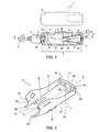
- connection to the lamp to be electrically powered is done by means of an electric cord 2, of which only one end connected to the housing 1 is shown in FIG. figure 1 .
- the housing 1 comprises a casing in two mutually separable and complementary parts, each of which partially delimits an internal housing 3 and which is a body 4 and a lid 5 for closing an opening 6 of lateral access to this housing 3.
- An attached bottom 7 constituting the housing 1 is mounted in the body 4, on the opposite side to the opening 6.
- the housing 1 and the housing 3 are elongate along the same longitudinal axis X-X '.
- the opening 6 extends substantially over the entire length L of the housing 3.
- the body 4 has two contacts or poles 9 and 10 of opposite polarities, which are offset transversely from each other by being disposed on either side of the longitudinal axis X- X '.
- Each pole 9 or 10 is provided for the connection of a terminal of a standard battery and is part of electrical connection connections of one, optionally, two interchangeable sources of electrical energy, in a supply circuit of the portable lamp.
- These connections comprise connections which connect the poles 9 and 10 to two conductive wires of the cords 2, in a manner known per se, and which are masked by the bottom 7.
- the electrical connections also comprise a contact 11.
- the contact 11 is intended to connect two batteries, in a manner that is specified below. It is fixed in the body 4, at the bottom 7, at the end 12 of the housing 3, that is to say opposite the end 8.
- connection means equipping the housing 1 have the form of a socket 13 for connecting a removable battery. Like the poles 9 and 10, this socket 13 is electrically connected to the two son of the cord 2, in a manner known per se.
- the base 20 forms one of two elastically flexible strips 24 symmetrical, each of which carries one of the two branches 21 and 22, at its distal end, and which are elastic return blades of these branches 21 and 22 towards each other.
- Each blade 24 is pierced with a slot 25 for reducing its bending stiffness.
- Each branch 21 or 22 is generally rectilinear and extends substantially at right angles from a blade 24.
- the two blades 24 are inclined towards the interior of the housing 3, several degrees around a transverse axis Y-Y ', relative to the transverse plane containing this axis.
- the branches 21 and 22 are inclined towards each other, so as to approach one another, and the longitudinal axis X-X ', as and when they move away from the base 20.
- Each branch 21 or 22 is provided with a retaining wing 15 at the bottom 7.
- the two wings 15 are projecting in the same plane towards each other. Once in the operational position, they penetrate behind the bottom 7 so as to be hooked while being able to slide relative to relative distance and thus accompany a tilting of the branches 21 and 22 relative to each other, around the l Y-axis'.
- the bases of the wings 15 also form stops to stop the bringing together of the two branches 21 and 22 towards each other, at a minimum spacing value.
- This minimum value is advantageously chosen so that the engagement of the battery A between the two branches 21 and 22 remains an easy operation.
- each branch 21 or 22 has a free end which forms a terminal 26 or 27 for connecting a terminal of a battery, facing one of the poles 9 and 10, as well as a finger 28 or 29 supporting one end of the body of the same battery in front of this terminal 26 or 27.
- terminals 26 and 27 are of opposite polarities.
- the terminal 26 defined by the branch 21 is a plus terminal, that is to say of positive polarity, which the symbol "+” pierced in this branch 21 indicates clearly visible.
- the terminal 27 defined by the branch 22 is a minus terminal, that is to say of negative polarity, which the symbol "-" pierced in this branch 22 indicates in a clearly visible manner.
- Each of the fingers 28 and 29 is part of the wedging means of a stack in operational position. Another part of these wedging means is in the form of supports 30 that the bottom 7 defines near the end 8 of the housing 3, as can be seen in FIG. figure 3 .
- the inner wall of this housing 3 also contributes to the setting of the two batteries together, one against the other.
- each of the branches 21 and 22 defines one of two ramps 31 of a convergent guide 32 to a slot-shaped longitudinal space 33 between these two branches.
- this slot 33 opens laterally to the access opening 6 to the housing 3, as can be seen at the figure 3 .
- the housing 1 is compact, simple and inexpensive with respect to its multiple possibilities of operation, which is advantageous. It is also robust.
- the cover 5 is removed and a source of electrical energy such as an accumulator or a pair of batteries can be installed in the body 4.
- a source of electrical energy such as an accumulator or a pair of batteries can be installed in the body 4.
- the branches 21 and 22 are inclined towards one the other so as to penetrate progressively into the central part of the housing 3.
- the plus terminal 26 and the minus terminal 27 are respectively facing the minus pole 9 and the plus pole 10.
- a removable battery A is in place in the body 4.
- this accumulator A or rechargeable battery is placed in front of the opening 6, parallel to the longitudinal axis X-X '.
- the branches 21 and 22 enter the receiving volume of the accumulator A.
- one side of the accumulator A is engaged against the convergent 32.
- the accumulator A sinks between the branches 21 and 22 as indicated by the arrow E at the figure 3 , being guided between them by the ramps 31 of the convergent 32, at the same time it pushes these branches outwardly.
- the arrows B symbolize the reversible tilting of the branches 21 and 22 to the outside, under the centrifugal thrust of the accumulator A.
- branches 21 and 22 have been previously separated by the accumulator A and are out of the reception volume of this accumulator A. Having been tilted by elastic deformation of the contact 11 and in particular of its return blades 24, the branches 21 and 22 clamp the accumulator A together and, in doing so, form a gripper which holds this accumulator A in place, which is advantageous.
- a male connection block of the battery A is plugged into the socket 13.
- the cover 5 can be replaced in front of the opening 6, after which the closed housing 1 is operational as a power supply of a lamp.
- the bodies C of the P cells are wedged together, against each other, between two walls facing the housing 1. Each of them rests on both a finger 28 or 29 and a support 30. In this way one battery P is connected to the pole 9 and the terminal 26, while the other battery P is connected to the pole 10 and to the terminal 27.
- the batteries P are connected in series in a power supply circuit of the portable lamp in that the contact 11 connects the minus terminal B-of one of them to the plus terminal B + of the other battery P.
- the use of the housing 1 is all the more reliable that a change in the type of electrical energy source does not require the use of an independent accessory and may be lost.
- the invention is not limited to the embodiment described above.
- the power supply device according to the invention can be integrated with this lamp to form with it a compact assembly.
Abstract
Description
L'invention se rapporte au domaine des lampes électriques portatives, dont les lampes dites « frontales » qui se portent au niveau du front de manière à éclairer vers l'avant, en pouvant par exemple s'ajuster sur un casque. Plus précisément, l'invention est relative à un dispositif d'alimentation électrique d'une lampe portative, du genre comprenant une enveloppe, ainsi que des connexions électriques de raccordement, dans un circuit d'alimentation, de l'une, au choix, de deux sources interchangeables d'énergie électrique que sont un accumulateur et un jeu d'au moins deux piles. Dans le dispositif d'alimentation électrique du genre considéré ici, les connexions électriques comportent un contact de raccordement d'une borne d'une des piles à une borne de l'autre pile, tandis que l'enveloppe délimite un logement d'accueil soit des piles ensemble soit de l'accumulateur.The invention relates to the field of portable electric lamps, including so-called "front" lamps that are worn at the forehead so as to illuminate forward, for example by being able to fit on a helmet. More specifically, the invention relates to a power supply device for a portable lamp, of the type comprising an envelope, as well as electrical connection connections, in a power supply circuit, of one, as desired, two interchangeable sources of electrical energy that are an accumulator and a set of at least two batteries. In the power supply device of the type considered here, the electrical connections comprise a connection contact of a terminal of one of the stacks to a terminal of the other stack, while the envelope delimits a housing of either batteries together either of the accumulator.
Une lampe électrique portative est classiquement pourvue d'une ou plusieurs sources lumineuses qui sont généralement choisies parmi les LEDs ou les ampoules et qui sont alimentées par une source d'énergie électrique. Cette source d'énergie électrique comporte des moyens de stockage d'énergie qui peuvent présenter la forme d'une ou plusieurs piles ou celle d'un ou plusieurs accumulateurs rechargeables ou batteries.A portable electric lamp is conventionally provided with one or more light sources which are generally chosen from LEDs or bulbs and which are powered by a source of electrical energy. This source of electrical energy comprises energy storage means which may be in the form of one or more batteries or that of one or more rechargeable accumulators or batteries.
Une pile possède des dimensions extérieures standardisées qui la rendent à la fois interchangeable avec une autre du même type et adaptable à de nombreux appareils différents. Du fait de sa large diffusion, une pile est souvent disponible dans de nombreux commerces et un approvisionnement en piles est généralement aisé, même dans des régions isolées et/ou sauvages qui sont justement des zones privilégiées d'emploi de lampes portatives.A battery has standardized external dimensions that make it both interchangeable with another of the same type and adaptable to many different devices. Because of its wide distribution, a battery is often available in many shops and a supply in batteries is generally easy, even in isolated and / or wild areas which are precisely preferred areas of use of portable lamps.
Un accumulateur rechargeable ou batterie présente d'autres avantages que les piles. En particulier, un accumulateur rechargeable peut conférer une plus grande autonomie, en fournissant une alimentation électrique pendant une durée plus conséquente.A rechargeable battery or battery has other advantages than batteries. In particular, a rechargeable battery can provide greater autonomy, providing a power supply for a longer period.
Des lampes portatives ont été conçues pour pouvoir être alimentées de deux manières alternatives et complémentaires, plus précisément par pile(s) ou par accumulateur(s). L'emploi de telles lampes permet de cumuler des avantages de l'alimentation par pile(s) et des avantages de l'alimentation par accumulateur(s).Portable lamps have been designed to be powered in two alternative and complementary ways, more precisely by battery (s) or accumulator (s). The use of such lamps makes it possible to combine the advantages of the battery power supply and the advantages of the battery supply (s).
En outre, un avantage particulier procuré par une lampe portative à alimentation par pile(s) ou par accumulateur consiste à pouvoir mettre en oeuvre une stratégie dans laquelle on choisit prioritairement l'alimentation par accumulateur et, en cas de panne ou de décharge complète de l'accumulateur, on utilise des piles en remplacement, comme alimentation de secours et/ou comme recharges normales. Une telle stratégie suppose d'emporter avec soi des piles de rechange, qui présentent généralement les avantages d'être moins lourdes, moins volumineuses et moins coûteuses qu'un accumulateur rechargeable.In addition, a particular advantage provided by a battery-powered portable lamp or accumulator consists of being able to implement a strategy in which the battery supply is primarily chosen and, in the event of a breakdown or complete discharge of the battery, the battery, replacement batteries are used as backup power and / or as normal recharges. Such a strategy involves bringing with you spare batteries, which generally have the advantages of being lighter, less bulky and less expensive than a rechargeable battery.
Toutefois, une difficulté à résoudre est que la pile n'a pas le même format que l'accumulateur, ni la même façon de se connecter dans la lampe.However, one difficulty to solve is that the battery does not have the same format as the battery, nor the same way to connect in the lamp.
Dans la demande de brevet français
Dans la demande de brevet français
Dans la demande de brevet
L'invention a au moins pour but de rendre possible une réduction du coût d'un dispositif prévu pour alimenter électriquement une lampe portative en permettant un choix quant au type d'alimentation, parmi une alimentation par pile(s) et une alimentation par accumulateur(s).The aim of the invention is at least to make it possible to reduce the cost of a device intended to power a portable lamp by allowing a choice as to the type of power supply, among a battery supply (s) and a battery supply (s).
Selon l'invention, ce but est atteint grâce à un dispositif d'alimentation qui est du genre précité et dans lequel le contact comporte une pince déformable entre une première configuration, dans laquelle chacune de deux branches en regard constitutive de cette pince est positionnée pour connecter l'une desdites bornes en pénétrant dans un volume de réception de l'accumulateur, et une deuxième configuration, dans laquelle les deux branches sont placées hors dudit volume de réception laissé libre entre ces deux branches.According to the invention, this object is achieved by means of a feeding device which is of the aforementioned kind and in which the contact comprises a deformable clip between a first configuration, in which each of two constituent branches of this clip is positioned to connect one of said terminals into a receiving volume of the accumulator, and a second configuration, wherein the two branches are placed outside said reception volume left free between these two branches.
Outre l'atteinte du but précité, l'invention peut permettre l'obtention d'un ou plusieurs avantages additionnels, parmi lesquels il y a un moindre encombrement, une simplification, un usage facilité, une robustesse accrue et une plus grande fiabilité d'usage.In addition to achieving the above purpose, the invention can provide one or more additional advantages, among which there is a smaller footprint, simplification, ease of use, increased robustness and greater reliability of use.
De préférence, des moyens de calage des deux piles dans le logement sont en plusieurs parties. Préférentiellement, chaque branche définit une borne de connexion d'une pile, ainsi qu'une partie de ces moyens de calage.Preferably, means for wedging the two batteries in the housing are in several parts. Preferably, each branch defines a connection terminal of a battery, as well as a part of these calibration means.
Avantageusement, parmi les parties des moyens de calage, au moins la partie définie par l'une des branches présente la forme d'une portion de support d'une extrémité d'un corps d'une des piles devant la borne de connexion définie par cette branche.Advantageously, among the parts of the wedging means, at least the portion defined by one of the branches has the shape of a support portion of an end of a body of one of the stacks in front of the connection terminal defined by this branch.
De préférence, la pince forme une pince de préhension de l'accumulateur.Preferably, the clip forms a grip gripper of the accumulator.
Préférentiellement, chaque branche comporte l'une de deux rampes d'un convergent de guidage de l'accumulateur vers un espace entre les deux branches lors d'une mise en place de cet accumulateur dans ledit volume de réception.Preferably, each branch comprises one of two ramps of a converging guide of the accumulator towards a space between the two branches when placing this accumulator in said receiving volume.
Avantageusement, le contact est rappelé élastiquement vers sa première configuration en étant déformable élastiquement de cette première configuration à sa deuxième configuration.Advantageously, the contact is resiliently returned to its first configuration by being elastically deformable from this first configuration to its second configuration.
De préférence, le dispositif d'alimentation électrique comporte des butées d'arrêt aptes à empêcher les branches de se rapprocher l'une de l'autre au delà de la deuxième configuration.Preferably, the power supply device comprises stoppers capable of preventing the branches from approaching each other beyond the second configuration.
Avantageusement, les deux branches du contact s'étendent de part et d'autre d'un axe longitudinal du logement, sensiblement depuis une première extrémité du logement qui comporte une deuxième extrémité à l'opposé de cette première extrémité. Préférentiellement, chaque branche comporte une extrémité libre entre les première et deuxième extrémités du logement.Advantageously, the two branches of the contact extend on either side of a longitudinal axis of the housing, substantially from a first end of the housing which has a second end opposite this first end. Preferably, each branch has a free end between the first and second ends of the housing.
De préférence, l'extrémité libre de chaque branche définit une borne de connexion d'une des piles.Preferably, the free end of each branch defines a connection terminal of one of the stacks.
Avantageusement, le logement comporte une longueur selon laquelle s'étend une ouverture d'accès latéral à ce logement, auquel cas l'enveloppe comporte un couvercle de fermeture de cette ouverture latérale. Préférentiellement, les deux branches délimitent entre elles un espace ayant globalement la forme d'une fente qui débouche latéralement vers l'ouverture d'accès au logement.Advantageously, the housing comprises a length according to which extends a lateral access opening to this housing, in which case the envelope comprises a closure cover of this lateral opening. Preferably, the two branches delimit between them a space having generally the shape of a slot which opens laterally to the access opening to the housing.
De préférence, le contact comporte une embase de montage qui relie les deux branches l'une à l'autre.Preferably, the contact comprises a mounting base which connects the two branches to one another.
Avantageusement, chaque branche comporte une aile de retenue à un fond du logement et de guidage de cette branche en rapprochement-éloignement par rapport à l'autre branche. Cette aile de retenue et de guidage est engagée derrière une portion du fond, de manière à être retenue dans la direction opposée à ce fond et à pouvoir coulisser parallèlement à un mouvement de rapprochement-éloignement relatif des deux branches. De préférence, les ailes de retenue et de guidage forment en outre des butées pour stopper le rapprochement des deux branches l'une vers l'autre à une valeur minimale d'écartement. Cette valeur minimale est avantageusement choisie pour que l'engagement de l'accumulateur entre les deux branches demeure une opération aisée.Advantageously, each branch comprises a retaining flange at a bottom of the housing and guiding this branch toward and away from the other branch. This retaining and guiding wing is engaged behind a portion of the bottom, so as to be retained in the opposite direction to the bottom and to be able to slide parallel to a movement of approximation-relative removal of the two branches. Preferably, the retaining and guiding wings also form stops to stop the bringing together of the two branches towards each other at a minimum spacing value. This minimum value is advantageously chosen so that the engagement of the battery between the two branches remains an easy operation.
Préférentiellement, le contact est réalisé dans un flan métallique mis en forme.Preferably, the contact is made in a shaped metal blank.
Avantageusement, chaque branche est percée d'un symbole indiquant la polarité de la borne que définit cette branche.Advantageously, each branch is pierced with a symbol indicating the polarity of the terminal that defines this branch.
De préférence, le contact est une pièce d'un seul tenant. Il peut également comporter plusieurs pièces raccordées électriquement.Preferably, the contact is a single piece. It can also include several pieces electrically connected.
D'autres avantages et caractéristiques ressortiront plus clairement de la description qui va suivre d'un mode particulier de réalisation de l'invention donné à titre d'exemple non limitatif et représenté aux dessins annexés, parmi lesquels :
- la
figure 1 est une vue en plan d'un boîtier d'alimentation électrique conforme à l'invention et représente celui-ci dans un état ouvert, où un couvercle et le reste de ce boîtier sont dissociés ; - la
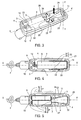
figure 2 est une vue en perspective d'un contact constitutif du boîtier représenté à lafigure 1 ; - la
figure 3 est une vue en perspective où le boîtier de lafigure 1 est représenté sans son couvercle ; - la
figure 4 est une vue analogue à lafigure 1 et représente le boîtier de cettefigure 1 sans son couvercle, ainsi qu'un accumulateur installé dans ce boîtier ; et - la
figure 5 est également une vue analogue à lafigure 1 et représente le boîtier de cettefigure 1 sans son couvercle, ainsi qu'une paire de piles installées et connectées dans ce boîtier, pour un fonctionnement alternatif à celui considéré à lafigure 4 .
- the
figure 1 is a plan view of a power supply box according to the invention and shows it in an open state, where a cover and the rest of this housing are dissociated; - the
figure 2 is a perspective view of a constituent contact of the housing shown in FIG.figure 1 ; - the
figure 3 is a perspective view where the case of thefigure 1 is represented without its lid; - the
figure 4 is a view similar to thefigure 1 and represents the case of thisfigure 1 without its cover, as well as an accumulator installed in this case; and - the
figure 5 is also a view similar to thefigure 1 and represents the case of thisfigure 1 without its cover, as well as a pair of batteries installed and connected in this case, for an alternative operation to that considered in thefigure 4 .
Sur la
Le raccordement à la lampe à alimenter électriquement se fait au moyen d'un cordon électrique 2, dont seulement une extrémité branchée au boîtier 1 est représentée à la
Le boîtier 1 comporte une enveloppe en deux parties dissociables l'une de l'autre et complémentaires, dont chacune délimite partiellement un logement interne 3 et qui sont un corps 4 et un couvercle 5 de fermeture d'une ouverture 6 d'accès latéral à ce logement 3. Un fond rapporté 7 constitutif du boîtier 1 est monté dans le corps 4, du côté opposé à l'ouverture 6.The
Le boîtier 1 et le logement 3 sont allongés selon un même axe longitudinal X-X'. L'ouverture 6 s'étend sensiblement sur toute la longueur L du logement 3.The
A une extrémité 8 du logement 3, le corps 4 possède deux contacts ou pôles 9 et 10 de polarités opposées, qui sont décalés transversalement l'un de l'autre en étant disposés de part et d'autre de l'axe longitudinal X-X'. Chaque pôle 9 ou 10 est prévu pour la connexion d'une borne d'une pile standard et fait partie de connexions électriques de raccordement de l'une, au choix, de deux sources interchangeables d'énergie électrique, dans un circuit d'alimentation de la lampe portative. Ces connexions comprennent des raccordements qui relient les pôles 9 et 10 à deux fils conducteurs du cordons 2, d'une manière connue en soi, et qui sont masqués par le fond 7. Les connexions électriques comportent également un contact 11.At one
Se trouvant dans le logement 3, le contact 11 est destiné à raccorder deux piles, d'une manière qui est précisée plus loin. Il est fixé dans le corps 4, au fond 7, au niveau de l'extrémité 12 du logement 3, c'est-à-dire à l'opposé de l'extrémité 8.Located in the
D'autres moyens de connexion équipant le boîtier 1 présentent fa forme d'une prise femelle 13 pour le branchement d'un accumulateur amovible. Comme les pôles 9 et 10, cette prise 13 est électriquement reliée aux deux fils conducteurs du cordon 2, d'une manière connue en soi.Other connection means equipping the
Sur la
Pour sa retenue par accrochage au fond 7, l'embase 20 est pourvue d'une languette 23 en saillie selon une direction parallèle à l'axe X-X', vers l'extrémité 8 du logement 3.For its retention by hooking to the
De chaque côté de cette languette 23, l'embase 20 forme l'une de deux lames élastiquement flexibles 24 symétriques, dont chacune porte l'une des deux branches 21 et 22, à son extrémité distale, et qui sont des lames de rappel élastique de ces branches 21 et 22 l'une vers l'autre. Chaque lame 24 est percée d'une fente 25 de réduction de sa raideur en flexion.On each side of this
Chaque branche 21 ou 22 est globalement rectiligne et s'étend sensiblement à angle droit à partir d'une lame 24. Les deux lames 24 sont inclinées vers l'intérieur du logement 3, de plusieurs degrés autour d'un axe transversal Y-Y', par rapport au plan transversal contenant cet axe. De la sorte, les branches 21 et 22 sont inclinées l'une vers l'autre, de manière à se rapprocher l'une de l'autre, et de l'axe longitudinal X-X', au fur et à mesure qu'elles s'éloignent de l'embase 20.Each
Chaque branche 21 ou 22 est pourvue d'une aile 15 de retenue au fond 7. Les deux ailes 15 sont en saillies dans un même plan, l'une vers l'autre. Une fois en position opérationnelle, elles pénètrent derrière le fond 7 de manière à y être accrochées tout en pouvant coulisser en rapprochement-éloignement relatif et ainsi accompagner un basculement des branches 21 et 22 l'une par rapport à l'autre, autour de l'axe Y-Y'.Each
Les bases des ailes 15 forment en outre des butées pour stopper le rapprochement des deux branches 21 et 22 l'une vers l'autre, à une valeur minimale d'écartement. Cette valeur minimale est avantageusement choisie pour que l'engagement de l'accumulateur A entre les deux branches 21 et 22 demeure une opération aisée.The bases of the
A l'opposé de l'embase 20, chaque branche 21 ou 22 possède une extrémité libre qui forme une borne 26 ou 27 de connexion d'une borne d'une pile, en regard d'un des pôles 9 et 10, ainsi qu'un doigt 28 ou 29 de support d'une extrémité du corps de la même pile devant cette borne 26 ou 27.Opposite the
Comme les pôles 9 et 10, les bornes 26 et 27 sont de polarités opposées. La borne 26 définie par la branche 21 est une borne plus, c'est-à-dire de polarité positive, ce que le symbole « + » percé dans cette branche 21 indique de manière nettement visible. La borne 27 définie par la branche 22 est une borne moins, c'est-à-dire de polarité négative, ce que le symbole « - » percé dans cette branche 22 indique de manière nettement visible.Like the
Chacun des doigts 28 et 29 fait partie de moyens de calage d'une pile en position opérationnelle. Une autre partie de ces moyens de calage présente la forme de supports 30 que le fond 7 définit à proximité de l'extrémité 8 du logement 3, ainsi qu'on peut le voir à la
De manière visible à la
Le boîtier 1 est compact, simple et peu coûteux eu égard à ses possibilités multiples de fonctionnement, ce qui est avantageux. Il est en outre robuste.The
Sur la
Sur la
Sur la
Toujours sur la
Lorsque l'on retire l'accumulateur A, le rappel élastique exercé principalement par les lames 24 ramène les branches 21 et 22 dans leur position d'origine, à savoir celle de la
En l'absence de l'accumulateur A, la mise en place de deux piles dans le corps 4 s'effectue donc d'une manière classique, sans une quelconque manoeuvre des branches 21 et 22. Le symbole « + » dans la branche 21 indique alors le sens d'installation d'une pile entre le pôle 9 et la borne 26 de polarités opposées. De même, le symbole « - » dans la branche 22 indique le sens d'installation d'une autre pile entre le pôle 10 et la borne 27 de polarités opposées.In the absence of the battery A, the introduction of two batteries in the
Sur la
Les corps C des piles P sont calés ensemble, l'un contre l'autre, entre deux parois en regard du boîtier 1. Chacun d'eux repose à la fois sur un doigt 28 ou 29 et sur un support 30. De la sorte, une pile P est connectée au pôle 9 et à la borne 26, tandis que l'autre pile P est connectée au pôle 10 et à la borne 27. Les piles P sont raccordées en série dans un circuit d'alimentation de la lampe portative, dans la mesure où le contact 11 raccorde la borne moins B-de l'une d'elles à la borne plus B+ de l'autre pile P.The bodies C of the P cells are wedged together, against each other, between two walls facing the
Comme l'installation et le retrait de l'accumulateur A, l'installation et le retrait des piles P s'effectuent aisément, ce qui est avantageux.Like the installation and removal of the battery A, the installation and removal of the batteries P is easy, which is advantageous.
De plus, l'utilisation du boîtier 1 est d'autant plus fiable qu'un changement du type de source d'énergie électrique ne requiert pas l'usage d'un accessoire indépendant et susceptible d'être égaré.In addition, the use of the
L'invention ne se limite pas au mode de réalisation décrit précédemment. En particulier, au lieu de présenter la forme d'un boîtier 1 séparé de la lampe à alimenter électriquement, le dispositif d'alimentation électrique conforme à l'invention peut être intégré à cette lampe pour former avec celle-ci un ensemble compact.The invention is not limited to the embodiment described above. In particular, instead of having the shape of a
Claims (13)
Applications Claiming Priority (1)
| Application Number | Priority Date | Filing Date | Title |
|---|---|---|---|
| FR1101630A FR2975750A1 (en) | 2011-05-26 | 2011-05-26 | DEVICE FOR ELECTRICALLY SUPPLYING A PORTABLE LAMP |
Publications (2)
| Publication Number | Publication Date |
|---|---|
| EP2527717A1 true EP2527717A1 (en) | 2012-11-28 |
| EP2527717B1 EP2527717B1 (en) | 2013-06-12 |
Family
ID=45932254
Family Applications (1)
| Application Number | Title | Priority Date | Filing Date |
|---|---|---|---|
| EP12354023.9A Not-in-force EP2527717B1 (en) | 2011-05-26 | 2012-03-28 | Power supply device of a portable lamp |
Country Status (4)
| Country | Link |
|---|---|
| US (1) | US9005784B2 (en) |
| EP (1) | EP2527717B1 (en) |
| CN (1) | CN102798101B (en) |
| FR (1) | FR2975750A1 (en) |
Families Citing this family (1)
| Publication number | Priority date | Publication date | Assignee | Title |
|---|---|---|---|---|
| US9954205B2 (en) | 2016-04-12 | 2018-04-24 | Energizer Brands, Llc | Slotted battery cavity for multiple cell sizes |
Citations (5)
| Publication number | Priority date | Publication date | Assignee | Title |
|---|---|---|---|---|
| FR2650123A1 (en) | 1989-07-19 | 1991-01-25 | Petzl Ets | HOUSING FOR ELECTRIC CYLINDRICAL BATTERIES OF DIFFERENT DIAMETERS |
| US20020060550A1 (en) | 2000-06-20 | 2002-05-23 | Franck Pautet | Power supply device for a portable apparatus, suitable for using different types of power supply |
| US20040038088A1 (en) * | 2002-08-21 | 2004-02-26 | Fuji Photo Film Co., Ltd. | Battery loading device for portable electronic apparatus |
| US20040081884A1 (en) * | 2002-10-25 | 2004-04-29 | Bean Heather N. | Dual-purpose compartment for a hybrid battery and fuel cell powered device |
| FR2941032A1 (en) | 2009-01-12 | 2010-07-16 | Zedel | DEVICE FOR SUPPLYING A BATTERY ELECTRIC LAMP BY BATTERY POWER OR A BATTERY, AND LAMP COMPRISING SUCH A DEVICE |
Family Cites Families (2)
| Publication number | Priority date | Publication date | Assignee | Title |
|---|---|---|---|---|
| US6942359B2 (en) * | 2003-12-08 | 2005-09-13 | Eveready Battery Company, Inc. | Flashlight that can operate with alternative size batteries |
| US7909478B2 (en) * | 2007-08-06 | 2011-03-22 | Fiskars Brands, Inc. | Multi battery type flashlight |
-
2011
- 2011-05-26 FR FR1101630A patent/FR2975750A1/en active Pending
-
2012
- 2012-03-28 EP EP12354023.9A patent/EP2527717B1/en not_active Not-in-force
- 2012-04-30 US US13/460,166 patent/US9005784B2/en not_active Expired - Fee Related
- 2012-05-24 CN CN201210163763.9A patent/CN102798101B/en not_active Expired - Fee Related
Patent Citations (5)
| Publication number | Priority date | Publication date | Assignee | Title |
|---|---|---|---|---|
| FR2650123A1 (en) | 1989-07-19 | 1991-01-25 | Petzl Ets | HOUSING FOR ELECTRIC CYLINDRICAL BATTERIES OF DIFFERENT DIAMETERS |
| US20020060550A1 (en) | 2000-06-20 | 2002-05-23 | Franck Pautet | Power supply device for a portable apparatus, suitable for using different types of power supply |
| US20040038088A1 (en) * | 2002-08-21 | 2004-02-26 | Fuji Photo Film Co., Ltd. | Battery loading device for portable electronic apparatus |
| US20040081884A1 (en) * | 2002-10-25 | 2004-04-29 | Bean Heather N. | Dual-purpose compartment for a hybrid battery and fuel cell powered device |
| FR2941032A1 (en) | 2009-01-12 | 2010-07-16 | Zedel | DEVICE FOR SUPPLYING A BATTERY ELECTRIC LAMP BY BATTERY POWER OR A BATTERY, AND LAMP COMPRISING SUCH A DEVICE |
Also Published As
| Publication number | Publication date |
|---|---|
| US9005784B2 (en) | 2015-04-14 |
| CN102798101A (en) | 2012-11-28 |
| US20120301752A1 (en) | 2012-11-29 |
| FR2975750A1 (en) | 2012-11-30 |
| EP2527717B1 (en) | 2013-06-12 |
| CN102798101B (en) | 2016-08-17 |
Similar Documents
| Publication | Publication Date | Title |
|---|---|---|
| FR2488060A1 (en) | POWER CABIN CONNECTOR WITH RESTRAINT SPRING | |
| EP2456024B1 (en) | Electric socket comprising a shutter | |
| CH656025A5 (en) | ELECTRICAL CONNECTOR. | |
| EP0246141A1 (en) | Box to show and orderly arrange an electric tool, such as a small electric drill | |
| EP3605749B9 (en) | Support for electrical equipment and associated electrical equipment | |
| EP0409744A1 (en) | Case for electric cylindrical batteries of different diameters | |
| EP2527717B1 (en) | Power supply device of a portable lamp | |
| FR3036546A1 (en) | CHARGING DEVICE FOR PORTABLE PHONES OR OTHER SIMILAR PORTABLE ELECTRONIC DEVICES | |
| EP2382690B1 (en) | Electric apparatus with an automatic connection terminal | |
| FR2967829A1 (en) | ELECTRICAL SOCKET HAVING MOBILE SIDE MOUNTS IN TRANSLATION | |
| EP0617536A1 (en) | Portable and compact radiotelephone terminal | |
| WO2002003761A1 (en) | Mobile illuminating device | |
| FR2806836A1 (en) | Battery adapter for D size battery, has upper housing with clearance opening in tube which extends from peripheral edge lying opposite flange, for accommodating positive pole | |
| EP2045881B1 (en) | Plug-in power socket including an opening socket body and a switching mobile terminal block | |
| EP2784885B1 (en) | Removable element for modular electrical equipment fitted with a swivel handle | |
| EP3709445A1 (en) | Electrical connector intended for an electrical appliance | |
| EP4077033A1 (en) | Method for connecting an electrical outlet of a vehicle to a connector | |
| FR2936656A1 (en) | Electric connection terminal e.g. phase terminal, for e.g. plug-in connector, has clamping spring with end branch that has anchoring portion inclined so as to orient sharp anchoring edge along direction opposite to introduction direction | |
| EP0903793B1 (en) | Battery casing for toys and toy comprising such casing | |
| FR3001835A1 (en) | TWO-PART BUILT-IN BOX | |
| EP4131659B1 (en) | Mechanism for power socket and associated power socket | |
| EP2456031A1 (en) | Electric facility including switchgear translatably mounted in an opening made in a wall | |
| EP1751827B1 (en) | Tool for stripping insulated electric conductor and a self-stripping terminal comprising said tool | |
| BE1022986B1 (en) | RECEIVER STATION AND PROTECTIVE CASE FOR A PORTABLE ELECTRONIC DEVICE | |
| EP0033675A1 (en) | Electric device with a safety fuse carrier |
Legal Events
| Date | Code | Title | Description |
|---|---|---|---|
| PUAI | Public reference made under article 153(3) epc to a published international application that has entered the european phase |
Free format text: ORIGINAL CODE: 0009012 |
|
| AK | Designated contracting states |
Kind code of ref document: A1 Designated state(s): AL AT BE BG CH CY CZ DE DK EE ES FI FR GB GR HR HU IE IS IT LI LT LU LV MC MK MT NL NO PL PT RO RS SE SI SK SM TR |
|
| AX | Request for extension of the european patent |
Extension state: BA ME |
|
| 17P | Request for examination filed |
Effective date: 20121213 |
|
| GRAP | Despatch of communication of intention to grant a patent |
Free format text: ORIGINAL CODE: EPIDOSNIGR1 |
|
| GRAS | Grant fee paid |
Free format text: ORIGINAL CODE: EPIDOSNIGR3 |
|
| GRAA | (expected) grant |
Free format text: ORIGINAL CODE: 0009210 |
|
| AK | Designated contracting states |
Kind code of ref document: B1 Designated state(s): AL AT BE BG CH CY CZ DE DK EE ES FI FR GB GR HR HU IE IS IT LI LT LU LV MC MK MT NL NO PL PT RO RS SE SI SK SM TR |
|
| REG | Reference to a national code |
Ref country code: GB Ref legal event code: FG4D Free format text: NOT ENGLISH |
|
| REG | Reference to a national code |
Ref country code: CH Ref legal event code: EP |
|
| REG | Reference to a national code |
Ref country code: AT Ref legal event code: REF Ref document number: 616830 Country of ref document: AT Kind code of ref document: T Effective date: 20130615 |
|
| REG | Reference to a national code |
Ref country code: IE Ref legal event code: FG4D Free format text: LANGUAGE OF EP DOCUMENT: FRENCH |
|
| REG | Reference to a national code |
Ref country code: DE Ref legal event code: R096 Ref document number: 602012000081 Country of ref document: DE Effective date: 20130808 |
|
| REG | Reference to a national code |
Ref country code: CH Ref legal event code: NV Representative=s name: CABINET ROLAND NITHARDT CONSEILS EN PROPRIETE , CH |
|
| PG25 | Lapsed in a contracting state [announced via postgrant information from national office to epo] |
Ref country code: LT Free format text: LAPSE BECAUSE OF FAILURE TO SUBMIT A TRANSLATION OF THE DESCRIPTION OR TO PAY THE FEE WITHIN THE PRESCRIBED TIME-LIMIT Effective date: 20130612 Ref country code: GR Free format text: LAPSE BECAUSE OF FAILURE TO SUBMIT A TRANSLATION OF THE DESCRIPTION OR TO PAY THE FEE WITHIN THE PRESCRIBED TIME-LIMIT Effective date: 20130913 Ref country code: SI Free format text: LAPSE BECAUSE OF FAILURE TO SUBMIT A TRANSLATION OF THE DESCRIPTION OR TO PAY THE FEE WITHIN THE PRESCRIBED TIME-LIMIT Effective date: 20130612 Ref country code: ES Free format text: LAPSE BECAUSE OF FAILURE TO SUBMIT A TRANSLATION OF THE DESCRIPTION OR TO PAY THE FEE WITHIN THE PRESCRIBED TIME-LIMIT Effective date: 20130923 Ref country code: SE Free format text: LAPSE BECAUSE OF FAILURE TO SUBMIT A TRANSLATION OF THE DESCRIPTION OR TO PAY THE FEE WITHIN THE PRESCRIBED TIME-LIMIT Effective date: 20130612 Ref country code: FI Free format text: LAPSE BECAUSE OF FAILURE TO SUBMIT A TRANSLATION OF THE DESCRIPTION OR TO PAY THE FEE WITHIN THE PRESCRIBED TIME-LIMIT Effective date: 20130612 Ref country code: NO Free format text: LAPSE BECAUSE OF FAILURE TO SUBMIT A TRANSLATION OF THE DESCRIPTION OR TO PAY THE FEE WITHIN THE PRESCRIBED TIME-LIMIT Effective date: 20130912 |
|
| REG | Reference to a national code |
Ref country code: AT Ref legal event code: MK05 Ref document number: 616830 Country of ref document: AT Kind code of ref document: T Effective date: 20130612 |
|
| REG | Reference to a national code |
Ref country code: NL Ref legal event code: VDEP Effective date: 20130612 |
|
| REG | Reference to a national code |
Ref country code: LT Ref legal event code: MG4D |
|
| PG25 | Lapsed in a contracting state [announced via postgrant information from national office to epo] |
Ref country code: BG Free format text: LAPSE BECAUSE OF FAILURE TO SUBMIT A TRANSLATION OF THE DESCRIPTION OR TO PAY THE FEE WITHIN THE PRESCRIBED TIME-LIMIT Effective date: 20130912 Ref country code: RS Free format text: LAPSE BECAUSE OF FAILURE TO SUBMIT A TRANSLATION OF THE DESCRIPTION OR TO PAY THE FEE WITHIN THE PRESCRIBED TIME-LIMIT Effective date: 20130612 Ref country code: HR Free format text: LAPSE BECAUSE OF FAILURE TO SUBMIT A TRANSLATION OF THE DESCRIPTION OR TO PAY THE FEE WITHIN THE PRESCRIBED TIME-LIMIT Effective date: 20130612 |
|
| PG25 | Lapsed in a contracting state [announced via postgrant information from national office to epo] |
Ref country code: LV Free format text: LAPSE BECAUSE OF FAILURE TO SUBMIT A TRANSLATION OF THE DESCRIPTION OR TO PAY THE FEE WITHIN THE PRESCRIBED TIME-LIMIT Effective date: 20130612 |
|
| PG25 | Lapsed in a contracting state [announced via postgrant information from national office to epo] |
Ref country code: EE Free format text: LAPSE BECAUSE OF FAILURE TO SUBMIT A TRANSLATION OF THE DESCRIPTION OR TO PAY THE FEE WITHIN THE PRESCRIBED TIME-LIMIT Effective date: 20130612 Ref country code: AT Free format text: LAPSE BECAUSE OF FAILURE TO SUBMIT A TRANSLATION OF THE DESCRIPTION OR TO PAY THE FEE WITHIN THE PRESCRIBED TIME-LIMIT Effective date: 20130612 Ref country code: CZ Free format text: LAPSE BECAUSE OF FAILURE TO SUBMIT A TRANSLATION OF THE DESCRIPTION OR TO PAY THE FEE WITHIN THE PRESCRIBED TIME-LIMIT Effective date: 20130612 Ref country code: IS Free format text: LAPSE BECAUSE OF FAILURE TO SUBMIT A TRANSLATION OF THE DESCRIPTION OR TO PAY THE FEE WITHIN THE PRESCRIBED TIME-LIMIT Effective date: 20131012 Ref country code: SK Free format text: LAPSE BECAUSE OF FAILURE TO SUBMIT A TRANSLATION OF THE DESCRIPTION OR TO PAY THE FEE WITHIN THE PRESCRIBED TIME-LIMIT Effective date: 20130612 Ref country code: PT Free format text: LAPSE BECAUSE OF FAILURE TO SUBMIT A TRANSLATION OF THE DESCRIPTION OR TO PAY THE FEE WITHIN THE PRESCRIBED TIME-LIMIT Effective date: 20131014 |
|
| PG25 | Lapsed in a contracting state [announced via postgrant information from national office to epo] |
Ref country code: PL Free format text: LAPSE BECAUSE OF FAILURE TO SUBMIT A TRANSLATION OF THE DESCRIPTION OR TO PAY THE FEE WITHIN THE PRESCRIBED TIME-LIMIT Effective date: 20130612 Ref country code: RO Free format text: LAPSE BECAUSE OF FAILURE TO SUBMIT A TRANSLATION OF THE DESCRIPTION OR TO PAY THE FEE WITHIN THE PRESCRIBED TIME-LIMIT Effective date: 20130612 Ref country code: NL Free format text: LAPSE BECAUSE OF FAILURE TO SUBMIT A TRANSLATION OF THE DESCRIPTION OR TO PAY THE FEE WITHIN THE PRESCRIBED TIME-LIMIT Effective date: 20130612 |
|
| PLBE | No opposition filed within time limit |
Free format text: ORIGINAL CODE: 0009261 |
|
| STAA | Information on the status of an ep patent application or granted ep patent |
Free format text: STATUS: NO OPPOSITION FILED WITHIN TIME LIMIT |
|
| PG25 | Lapsed in a contracting state [announced via postgrant information from national office to epo] |
Ref country code: DK Free format text: LAPSE BECAUSE OF FAILURE TO SUBMIT A TRANSLATION OF THE DESCRIPTION OR TO PAY THE FEE WITHIN THE PRESCRIBED TIME-LIMIT Effective date: 20130612 |
|
| 26N | No opposition filed |
Effective date: 20140313 |
|
| PG25 | Lapsed in a contracting state [announced via postgrant information from national office to epo] |
Ref country code: IT Free format text: LAPSE BECAUSE OF FAILURE TO SUBMIT A TRANSLATION OF THE DESCRIPTION OR TO PAY THE FEE WITHIN THE PRESCRIBED TIME-LIMIT Effective date: 20130612 |
|
| REG | Reference to a national code |
Ref country code: DE Ref legal event code: R097 Ref document number: 602012000081 Country of ref document: DE Effective date: 20140313 |
|
| PG25 | Lapsed in a contracting state [announced via postgrant information from national office to epo] |
Ref country code: LU Free format text: LAPSE BECAUSE OF FAILURE TO SUBMIT A TRANSLATION OF THE DESCRIPTION OR TO PAY THE FEE WITHIN THE PRESCRIBED TIME-LIMIT Effective date: 20140328 |
|
| REG | Reference to a national code |
Ref country code: IE Ref legal event code: MM4A |
|
| PG25 | Lapsed in a contracting state [announced via postgrant information from national office to epo] |
Ref country code: IE Free format text: LAPSE BECAUSE OF NON-PAYMENT OF DUE FEES Effective date: 20140328 |
|
| REG | Reference to a national code |
Ref country code: FR Ref legal event code: PLFP Year of fee payment: 4 |
|
| PGFP | Annual fee paid to national office [announced via postgrant information from national office to epo] |
Ref country code: DE Payment date: 20150324 Year of fee payment: 4 Ref country code: CH Payment date: 20150313 Year of fee payment: 4 |
|
| PGFP | Annual fee paid to national office [announced via postgrant information from national office to epo] |
Ref country code: FR Payment date: 20150309 Year of fee payment: 4 |
|
| PG25 | Lapsed in a contracting state [announced via postgrant information from national office to epo] |
Ref country code: MT Free format text: LAPSE BECAUSE OF FAILURE TO SUBMIT A TRANSLATION OF THE DESCRIPTION OR TO PAY THE FEE WITHIN THE PRESCRIBED TIME-LIMIT Effective date: 20130612 |
|
| PG25 | Lapsed in a contracting state [announced via postgrant information from national office to epo] |
Ref country code: SM Free format text: LAPSE BECAUSE OF FAILURE TO SUBMIT A TRANSLATION OF THE DESCRIPTION OR TO PAY THE FEE WITHIN THE PRESCRIBED TIME-LIMIT Effective date: 20130612 |
|
| PG25 | Lapsed in a contracting state [announced via postgrant information from national office to epo] |
Ref country code: MC Free format text: LAPSE BECAUSE OF FAILURE TO SUBMIT A TRANSLATION OF THE DESCRIPTION OR TO PAY THE FEE WITHIN THE PRESCRIBED TIME-LIMIT Effective date: 20130612 |
|
| PG25 | Lapsed in a contracting state [announced via postgrant information from national office to epo] |
Ref country code: CY Free format text: LAPSE BECAUSE OF FAILURE TO SUBMIT A TRANSLATION OF THE DESCRIPTION OR TO PAY THE FEE WITHIN THE PRESCRIBED TIME-LIMIT Effective date: 20130612 |
|
| PG25 | Lapsed in a contracting state [announced via postgrant information from national office to epo] |
Ref country code: TR Free format text: LAPSE BECAUSE OF FAILURE TO SUBMIT A TRANSLATION OF THE DESCRIPTION OR TO PAY THE FEE WITHIN THE PRESCRIBED TIME-LIMIT Effective date: 20130612 Ref country code: BE Free format text: LAPSE BECAUSE OF FAILURE TO SUBMIT A TRANSLATION OF THE DESCRIPTION OR TO PAY THE FEE WITHIN THE PRESCRIBED TIME-LIMIT Effective date: 20140331 Ref country code: HU Free format text: LAPSE BECAUSE OF FAILURE TO SUBMIT A TRANSLATION OF THE DESCRIPTION OR TO PAY THE FEE WITHIN THE PRESCRIBED TIME-LIMIT; INVALID AB INITIO Effective date: 20120328 |
|
| REG | Reference to a national code |
Ref country code: DE Ref legal event code: R119 Ref document number: 602012000081 Country of ref document: DE |
|
| REG | Reference to a national code |
Ref country code: CH Ref legal event code: PL |
|
| GBPC | Gb: european patent ceased through non-payment of renewal fee |
Effective date: 20160328 |
|
| REG | Reference to a national code |
Ref country code: FR Ref legal event code: ST Effective date: 20161130 |
|
| PG25 | Lapsed in a contracting state [announced via postgrant information from national office to epo] |
Ref country code: CH Free format text: LAPSE BECAUSE OF NON-PAYMENT OF DUE FEES Effective date: 20160331 Ref country code: FR Free format text: LAPSE BECAUSE OF NON-PAYMENT OF DUE FEES Effective date: 20160331 Ref country code: GB Free format text: LAPSE BECAUSE OF NON-PAYMENT OF DUE FEES Effective date: 20160328 Ref country code: LI Free format text: LAPSE BECAUSE OF NON-PAYMENT OF DUE FEES Effective date: 20160331 Ref country code: DE Free format text: LAPSE BECAUSE OF NON-PAYMENT OF DUE FEES Effective date: 20161001 |
|
| PG25 | Lapsed in a contracting state [announced via postgrant information from national office to epo] |
Ref country code: MK Free format text: LAPSE BECAUSE OF FAILURE TO SUBMIT A TRANSLATION OF THE DESCRIPTION OR TO PAY THE FEE WITHIN THE PRESCRIBED TIME-LIMIT Effective date: 20130612 |
|
| PG25 | Lapsed in a contracting state [announced via postgrant information from national office to epo] |
Ref country code: AL Free format text: LAPSE BECAUSE OF FAILURE TO SUBMIT A TRANSLATION OF THE DESCRIPTION OR TO PAY THE FEE WITHIN THE PRESCRIBED TIME-LIMIT Effective date: 20130612 |